

Crane D2003, D2004 Installation, Operating And Maintenance Instructions
INSTALLATION, OPERATING AND MAINTENANCE INSTRUCTIONS
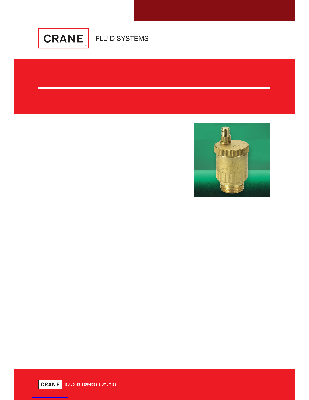
AUTOMATIC AIR VENT
D2003 & D2004
FUNCTION
Automatic air vent valves are designed to remove the air
that accumulates in heating and air conditioning systems
without the need for manual intervention. This prevents
harmful phenomena that may compromise the life and the
performance of the heating system and which include:
• Corrosion due to the oxygen.
• Pockets of air trapped in the heating emitters.
• Cavitation in the circulation pumps.
PRODUCT LIFE CYCLE
The life of the piping products is dependent on its application, frequency of use and freedom
from misuse. Compatibility with the system into which it is installed must be considered. The
properties of the fluid being transported such as pressure, temperature and the nature of the
fluid must be taken into account to minimise or avoid premature failure or non-operability.
A well-designed system will take into consideration all the factors considered in the piping
products design, but additionally electrolytic interaction between dissimilar metals in the piping
products and the system must be examined. Before commissioning a system, it should be
flushed to eliminate debris and chemically cleaned as appropriate to eliminate contamination,
all of which will prolong the life of the piping products.
LIMITS OF USE
These valves have been categorised in accordance with the Pressure Equipment Directive
2014/68/EU.
The fluid to be transported is limited to group 2 liquids i.e. non-hazardous.
On no account must these valves be used on any group 1 liquids, group 1 gases, group 2
gases or unstable fluids.
Note:- Valves are classified as SEP (sound engineering practice) and as such cannot be CE marked
and do not require a declaration of conformity.

AUTOMATIC AIR VENT: D2003 & D2004
2 3
AUTOMATIC AIR VENT: D2003 & D2004
OPERATING
During operation the upper cap in the standard version (black plastic cap for sizes 3/8” & 1/2”)
must be loosened.
The upper cap for the hygroscopic version (sizes 3/4” & 1”) must be completely hand tightened.
It is not advisable to fit the valve in places which could be subject to freezing.
Hygroscopic cap
3/4” and 1” models are equipped with a hygroscopic safety cap. Its functionality is based on
the properties of the fibre discs that serve as the seal cartridge and whose volume increases
by 50% as soon as they become wet and thus cause the valve to close. This way, possible
damages are avoided in case of leakage.
Models with shut-off
The automatic shut-off valve, which forms a seal with the valve body by means of an O-ring
made of EPDM, facilitates maintenance operations by shutting off the water flow when the valve
is removed and also allows for easy inspection
Note:- maximum discharge pressure 2.5 bar, system pressure must be under 2.5 bar to allow the air to
discharge automatically.
OPERATING PRESSURES AND TEMPERATURES
Not suitable for fatigue loading, creep conditions, fire testing, fire hazard environment, corrosive
or erosive service, transporting fluids with abrasive solids.
PRESSURE/TEMPERATURE RATING
These air vents are suitable for use up to 10 bar pressure rating. They must be installed in a
piping system where the normal pressure and temperature do not exceed the above ratings.
The maximum allowable pressure is for non-shock conditions. Water hammer and impact for
example, should be avoided.
If the limits of use specified in these instructions are exceeded or if the valve is used on
applications for which it was not designed, a potential hazard could result.
LAYOUT AND SITING
Care should be taken regarding orientation of the automatic air vent to enable full efficiency to
expel air from the system.
It should be considered at the design stage where air vents will be located to give access for
inspection maintenance and repair.
INSTALLATION, OPERATING AND MAINTENANCE INSTRUCTIONS
Fig. No PN
Non-shock pressure at
temperature range
Non-shock pressure at
max. temperature
D2003 PN10 10 bar from -10°C to 120°C 10 bar at 120°C
D2004 PN10 10 bar -10°C to 110°C 10 bar at 110°C
INSTALLATION
These air vents are threaded BSP parallel (external) and require a seal washer to ensure
leak tightness.
Air vents are precision manufactured items and as such, should not be subjected to misuse
such as careless handling, allowing dirt to enter, lack of system cleaning before operation and
excessive force during assembly.
All special packaging material must be removed.
The valve is installed in the vertical position, on the air separator, on manifolds, on riser pipes
and generally in parts of the system where a concentration of air pockets is to be expected.
MAINTENANCE
The D2003 & D2004 air vent is maintenance free.
However, the system should be at zero pressure and ambient temperature prior to
any inspection.
Maintenance Engineers & Operators are reminded to use correct fitting tools and equipment.
A full risk assessment and methodology statement must be compiled prior to any maintenance.
The risk assessment must take into account the possibility of the limits of use being exceeded
whereby a potential hazard could result.
A maintenance programme should therefore include checks on the development of unforeseen
conditions, which could lead to failure.
 Loading...