

Page 1
INSTALLATION, OPERATING AND MAINTENANCE INSTRUCTIONS
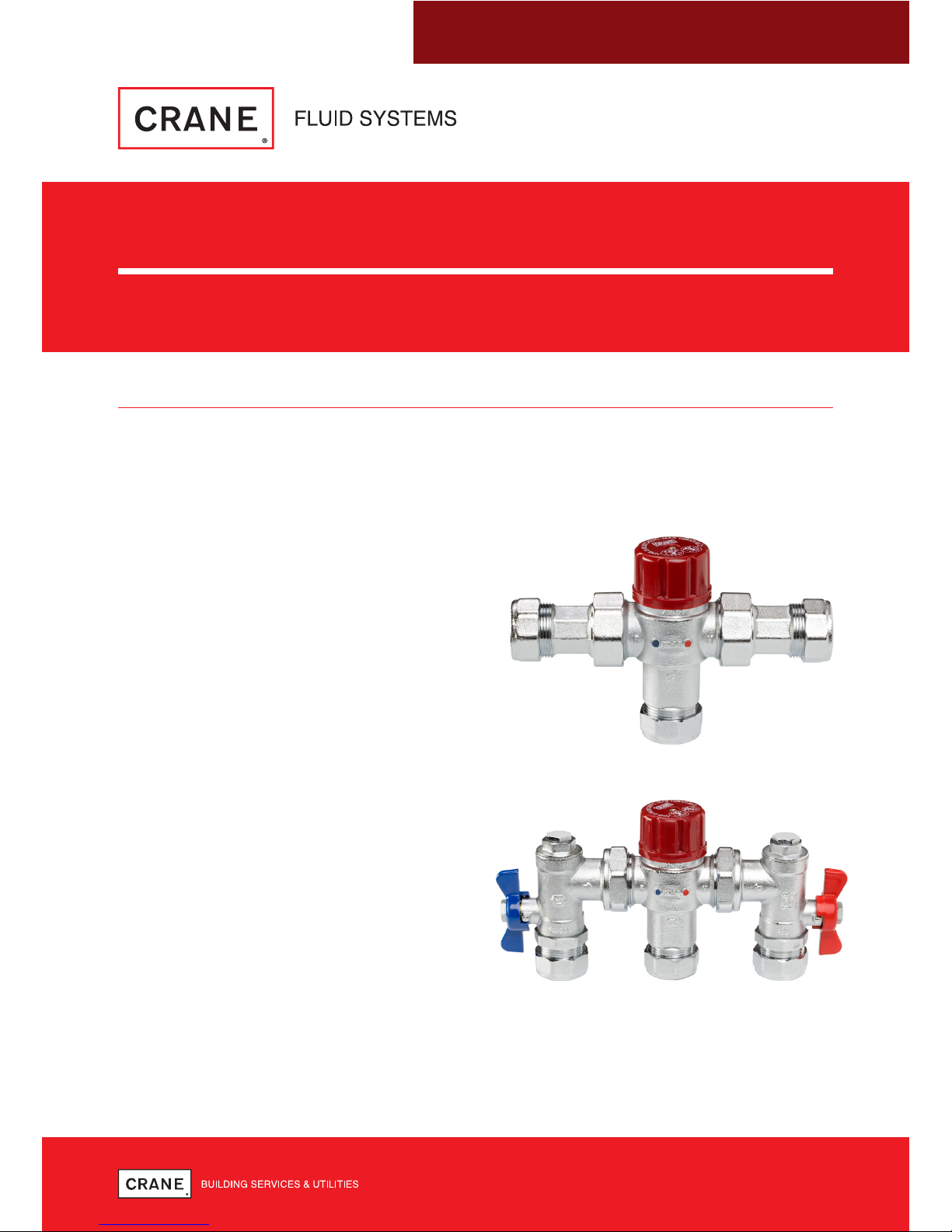
THERMOSTATIC MIXING VALVES
D1088 & D1089
INTRODUCTION
Are self-acting Thermostatic Mixing Valves designed to blend hot and cold water, to ensure a
constant, safe outlet temperature and prevent scalding.
• Design and manufactured to comply with
BS EN1287 and BS EN1111.
• Have been independently tested and
certified as meeting the requirements of the
D08 specification under the TMV3 scheme.
• The D1089 includes right angle isolation
valves.
• Both the D1088 & D1089 thermostatic
mixing valves are certified under the
BuildCert TMV2 & TMV3 schemes and are
WRAS approved products listed in the
WRAS Approvals Directory:
- BuildCert Approval Number (TMV3):
BC1802/1016 (for TMV3)
- BuildCert Approval Number (TMV2):
BC1801/1016 (for TMV2)
- WRAS Scheme Approval Number:
1301096 (WRAS)
D1089
D1088
Page 2
THERMOSTATIC MIXING VALVES: D1088 & D1089
2
TECHNICAL SPECIFICATION
Factory Setting
41°C
Temperature Setting Range
30°C to 50°C
Minimum Hot to Mix Temperature
10°C
Temperature Stability
±2°C
Maximum Working Pressure
10 Bar
Min Flow Rate
5 l/min
Table 1
GENERAL INSTALLATION – TMV2 & TMV3
These instructions are issued as guidelines only and may not cover all installation conditions –
if unsure please contact our Technical Helpline before installation.
• Crane FS products are designed for installation and use within suitably designed systems
reflecting CIBSE, BSRIA and HVAC guidelines. Particular care should be taking with regards
to accessibility to valve for setting/adjustment, tube cutting, jointing & bracketing/supports.
• The thermostatic mixing valve must be installed in accordance with the regulations of the
local water company and the Water Supply (Water Fittings) Regulations 1999.
• The D1088 & D1089 are suitable for single outlet applications only.
• The D1088 & D1089 can be installed in any orientation.
• Flush hot & cold supply pipework before connection.
• For the D1088, where isolation valves are not supplied, isolation valves in the water supply
inlets should be fitted as close as practical to the TMV.
• For D1088, wafer strainers are supplied as shown in figure 5.
• For D1089, strainers are supplied and located in the isolation valve body.
TMV3
The D1088 and D1089 have been approved as TYPE 3 valves under the TMV3 scheme. They
have been designed and manufactured for use in Healthcare and Commercial installations and
complying with NHS Estates requirements D 08.
LIMITS OF USE
The D1088 & D1089 have been approved for use on the following designated systems.
Code Operating Pressure Application
HP-S, LP-S High Pressure Shower Temperature 41ºC
HP-W, LP-W High Pressure Washbasin Temperature 41ºC
HP-B, LP-B High Pressure Bidet Temperature 38ºC
HP-T44, LP-T44 High Pressure Bath Fill Temperature 44ºC
HP-T46, LP-T46 High Pressure
Bath Fill (assisted)
Temperature 46ºC
Table 2 - Mixed Water Temperature
Note 1 - HP: High Pressure LP: Low Pressure Note 2 - 15mm not acceptable for LP Tub Fill, LP-T44 & LP-T46.
Page 3
3
THERMOSTATIC MIXING VALVES: D1088 & D1089
INSTALLATION, OPERATING AND MAINTENANCE INSTRUCTIONS
CONDITIONS OF USE
Operating Pressure Range High Pressure Low Pressure
Maximum Static Pressure 10 bar 10 bar
Flow Pressure - Hot & Cold 1 to 5 bar 0.2 - 1 bar
Hot Supply Temperature 52 to 65ºC 52 to 65ºC
Cold Supply Temperature 5 to 20ºC 5 to 20ºC
Table 3 - Normal Conditions of Use for Type 3 Valves
Note 1: The valve may perform adequately outside the conditions in table 3 but the TMV3 scheme approval does
not apply.
Note 2: The highest flow rates will be achieved under balanced pressure conditions, but the pressure at the valve
inlets must be within a ratio of 2:1 under flow conditions and the size and layout of pipe work and fittings must take
this into account.
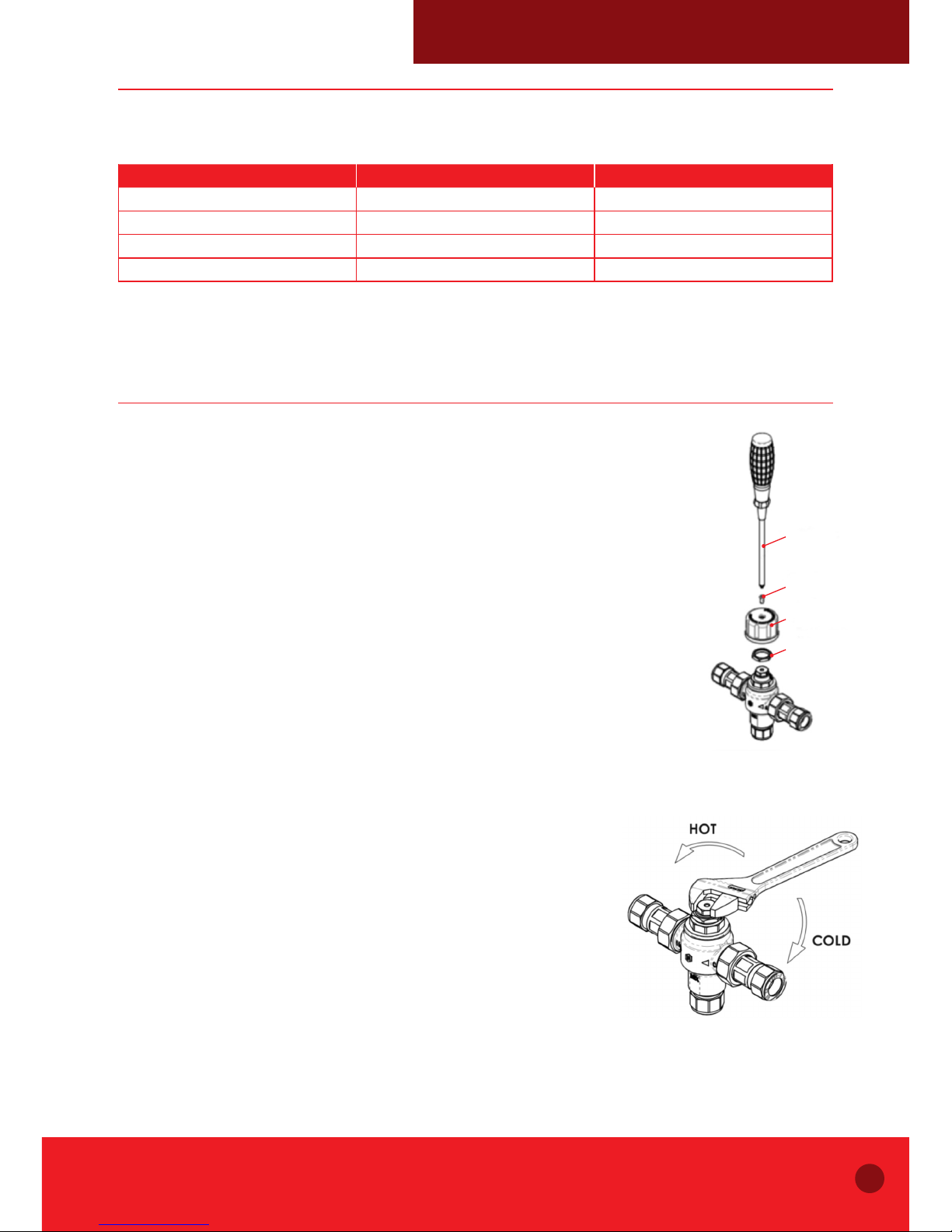
PRE-COMMISSIONING CHECKS
Follow this method for adjusting the water temperature:
1. Remove the maroon plastic protective cap on top of the valve with a
screw-driver.
2. Back-out the nut, using a monkey spanner:
- To increase the temperature turn anti-clockwise
- To decrease the temperature turn clockwise
- To set the valve to a maximum mixed water temperature in
accordance with the valve application (See Table 4).
Once the correct outlet temperature is set the internal mechanism must
be tested at least 3 times by:
• Alternately isolate the hot & cold water supply. This causes the internal
piston to travel its full stroke and will ensure correct operation
of the valve.
• With hot & cold isolation valves and the terminal outlet fully open retest
the flow temperature. If the set temperature has moved, repeat the
commissioning process.
• A fail safe test must be carried out by isolating the cold
supply. Once isolated, the flow must reduce, within a couple
of seconds, to a trickle - depending on site conditions, supply
temperature/pressure.
• Then repeat fail safe test isolating the hot supply. Once
isolated, the flow must reduce to a trickle within a couple of
seconds – depending on site conditions.
• If either the cold or hot fail safe function does not operate, check;
- Supply pressures
- Supply temperatures
- Hot water supply is at least 10ºC above required mix temperature,
i.e. minimum hot to mix temperature
Figure 1 - D1088 pictured,
cap removal
Figure 2 - D1088 pictured,
temperature setting
Screw driver
Screw
The blue plastic
protective cap
Nut
Page 4
THERMOSTATIC MIXING VALVES: D1088 & D1089
4
COMMISIONING
Since the installed supply conditions are likely to be different from those applied in the
laboratory tests, it is appropriate, at commissioning, to carry out some simple checks and tests
on each mixing valve to provide a performance reference point for future in-service tests.
a) The designation (TMV3) of the Thermostatic Mixing Valve matches the intended application.
b) The supply pressures are within the range of operating pressures for the designation of
the valve.
c) The supply temperatures are within the range permitted for the valve and within guidance
information on the prevention of legionella etc.
d) Record the temperature of the hot and cold water supplies.
e) Record the temperature of the mixed water at the largest draw-off flow rate.
f) Record the temperature of the mixed water at a smaller draw-off flow rate.
g) Isolate the cold water supply to the mixing valve and monitor the mixed water temperature.
h) Record the maximum temperature achieved as a result of (g) and the final
stabilised temperature.
Note: The final stabilised mixed water temperature should not exceed the values in the following table.
i) Use recording equipment such as a thermometer etc. used for the measurements.
Application Mixed Water Temperature
Bidet 40°C
Shower 43°C
Washbasin 43°C
Bath (44°C Fill) 46°C
Bath (46°C Fill) 48°C
Table 4 - Guide to Maximum Stabilised Temperatures Recorded During Site Tests
Page 5

5
THERMOSTATIC MIXING VALVES: D1088 & D1089
INSTALLATION, OPERATING AND MAINTENANCE INSTRUCTIONS
IN SERVICE TESTING
Purpose
The purpose of in-service tests is to regularly monitor and record the performance of the
Thermostatic Mixing Valve. Deterioration in performance can indicate the need for service work
on the valve and/or the water supplies.
Service Work Procedure
Using the same measuring equipment or equipment to the same specification as used in the
commissioning of the valve, adjust the temperature of the mixed water in accordance with the
requirement of the application. Carry out the following sequence:
a) Record the temperature of the hot and cold water supplies.
b) Record the temperature of the mixed water at the largest draw-off flow rate.
c) Record the temperature of the mixed water at a smaller draw-off flow rate, which shall be
measured.
If the mixed water temperature has changed significantly from the previous test results
(e.g.> 1 K), record the change and before re-adjusting the mixed water temperature check:
a) That any in-line or integral strainers are clean.
b) Any in-line or integral check valves or other anti-back siphonage devices are in good
working order.
c) Any isolating valves are fully open.
With an acceptable mixed water temperature, complete the following procedure:
a) Record the temperature of the hot and cold water supplies.
b) Record the temperature of the mixed water at the largest draw-off flow rate.
c) Record the temperature of the mixed water at a smaller draw-off flow rate, which shall be
measured.
d) Isolate the cold water supply to the mixing valve and monitor the mixed water temperature.
e) Record the maximum temperature achieved as a result of (d) and the final
stabilised temperature.
f) Record the equipment, thermometer etc. used for the measurements.
If at step (e) the final mixed water temperature is greater than the values in the above table and/
or the maximum temperature exceeds the corresponding value from the previous results by
more than about 2 K, the need for service work is indicated.
Note: In-service tests should be carried out with a frequency, which identifies a need for service work before an
unsafe water temperature can result. In the absence of any other instruction or guidance, the following procedure
described in Annex F of D08 may be used.
Page 6

THERMOSTATIC MIXING VALVES: D1088 & D1089
6
FREQUENCY OF IN-SERVICE TESTS (Annex F of D08)
General
In the absence of any other instruction or guidance on the means of determining the
appropriate frequency of in-service testing, the following procedure may be used:
a) 6 to 8 weeks after commissioning carry out the tests detailed in “In-Service Tests”.
b) 12 to 15 weeks after commissioning carry out the tests detailed in “In-Service Tests”.
Depending on the results of the above tests, several possibilities exist:
a) If no significant changes (e.g. ≤ 1 K) in mixed water temperatures are recorded between
commissioning and 6 to 8 week testing, or between commissioning and 12-15 week testing
the next in-service test can be deferred to 24 to 28 weeks after commissioning.
b) If small changes (e.g. 1 to 2 K) in mixed water temperatures are recorded in only one
of these periods, necessitating adjustment of the mixed water temperature, then the next
in-service test can be deferred to 24 to 28 weeks after commissioning.
c) If small changes (e.g. 1 to 2 K) in mixed water temperatures are recorded in both of these
periods, necessitating adjustment of the mixed water temperature, then the next in-service
test should be carried out at 18 to 21 weeks after commissioning.
d) If significant changes (e.g. > 2 K) in mixed water temperatures are recorded in either of
these periods, necessitating service work, then the next in-service test should be carried out
at 18 to 21 weeks after commissioning.
The general principle to be observed after the first 2 or 3 in-service tests is that the intervals of
future tests should be set to those which previous tests have shown can be achieved with no
more than a small change in mixed water temperature.
Page 7

7
THERMOSTATIC MIXING VALVES: D1088 & D1089
INSTALLATION, OPERATING AND MAINTENANCE INSTRUCTIONS
TMV2
The valves covered by these instructions have been specifically designed and manufactured as
being in compliance with BS EN1287 and BS EN1111. It has been independently tested and
approved as a TYPE 2 valve under TMV2 scheme for use in domestic situations.
LIMITS OF USE
The D1088 & D1089 have been approved for use on the following designated systems.
Code Operating Pressure Application
HP-S, LP-S High Pressure Shower Temperature 41ºC
HP-W, LP-W High Pressure Washbasin Temperature 41ºC
HP-B, LP-B High Pressure Bidet Temperature 38ºC
HP-T44 High Pressure Bath Fill Temperature 44ºC
Table 5 - Mixed Water Temperature
Note 1: HP: High Pressure LP: Low Pressure
Note 2: 46°C is the maximum permissible mixed water temperature from the bath tap. The maximum temperature
takes account of the allowable temperature tolerances inherent in thermostatic mixing valves and temperature losses
in metal baths. 46°C is not a safe bathing temperature for adults or children.
Note 3: The British Burns Association recommends 37 to 37.5°C as a comfortable bathing temperature for children.
In premises covered by the Care Standards Act 2000, the maximum mixed water outlet temperature is 43°C.
CONDITIONS OF USE
Operating Pressure Range High Pressure Low Pressure
Maximum Static Pressure 10 bar 10 bar
Flow Pressure - Hot & Cold 0.5 bar to 5.0 bar 0.1 bar to 1.0 bar
Hot Supply Temperature 55 to 65ºC 55 to 65ºC
Cold Supply Temperature ≤25°C ≤25°C
Table 6 - Normal Conditions of Use for Type 2 Valves
Note 1: Valves operating outside table 6’s conditions cannot be guarantees by the Scheme to operate as
Type 2 valves.
Note 2: Valves approved for designation of use H.P only, must state: - If a water supply is fed by gravity then the
supply pressure should be verified to ensure the conditions of use are appropriate for the valve.
Note 3: Valves approved for designation of use LP Tub applications that only achieve the minimum flow rate
requirement at a supply pressure of 0.2 bar must indicate that the minimum supply pressure for LP Tub application
is 0.2 bar.
Page 8

THERMOSTATIC MIXING VALVES: D1088 & D1089
8
PRE-COMMISSIONING CHECKS
Follow this method for adjusting the water temperature:
1. Remove the maroon plastic protective cap on top of the valve with
a screw-driver.
2. Back-out the nut, using a monkey spanner:
- To increase the temperature turn anti-clockwise
- To decrease the temperature turn clockwise
- To set the valve to a maximum mixed water temperature in
accordance with the valve application (See Table 7).
Once the correct outlet temperature is set the internal mechanism must
be tested at least 3 times by:
• Alternately isolate the hot & cold water supply. This causes the
internal piston to travel its full stroke and will ensure correct operation
of the valve.
• With hot & cold isolation valves and the terminal outlet fully
open retest the flow temperature. If the set temperature has
moved, repeat the commissioning process
• A fail safe test must be carried out by isolating the cold
supply. Once isolated, the flow must reduce, within a
couple of seconds, to a trickle – depending on site
conditions, supply temperature/pressure
• Then repeat fail safe test isolating the hot supply. Once
isolated, the flow must reduce to a trickle within a couple of
seconds – depending on site conditions.
• If either the cold or hot fail safe function does not operate, check;
- Supply pressures
- Supply temperatures
- Hot water supply is at least 10ºC above required mix temperature, i.e. minimum
hot to mix temperature
• TMVs shall be located in such a way that it can be easy accessed for maintenance and
commissioning purposes.
Figure 3 - D1088 pictured,
cap removal
Figure 4 - D1088 pictured,
temperature setting
Screw driver
Screw
The blue plastic
protective cap
Nut
Page 9

9
THERMOSTATIC MIXING VALVES: D1088 & D1089
INSTALLATION, OPERATING AND MAINTENANCE INSTRUCTIONS
COMMISIONING
Since the installed supply conditions are likely to be different from those applied in the
laboratory tests, it is appropriate, at commissioning, to carry out some simple checks and tests
on each mixing valve to provide a performance reference point for future in-service tests.
a) The designation (TMV2) of the Thermostatic Mixing Valve matches the intended application.
b) The supply pressures are within the valves operating range.
c) The supply temperatures are within the range permitted for the valve and within guidance
information on the prevention of legionella etc.
d) Record the temperature of the hot and cold water supplies.
e) Record the temperature of the mixed water at the largest draw-off flow rate.
f) Record the temperature of the mixed water at a smaller draw-off flow rate.
g) Isolate the cold water supply to the mixing valve and monitor the mixed water temperature.
h) Record the maximum temperature achieved as a result of (g) and the final stabilised
temperature.
i) NOTE: The final stabilised mixed water temperature should not exceed the values in the
following table.
j) Use recording equipment, such as a thermometer etc.
k) The mixed water temperature at the terminal fitting must never exceed 46°C.
Application Mixed Water Temperature
Bidet 40°C
Shower 43°C
Washbasin 43°C
Bath (44°C Fill) 46°C
Table 7 - Guide to Maximum Stabilised Temperatures Recorded During Site Tests
Page 10

THERMOSTATIC MIXING VALVES: D1088 & D1089
10
IN SERVICE TESTING
It is a requirement that all TMV2 approved valves shall be verified against the original set
temperature results once a year. When commissioning/testing is due the following performance
checks shall be carried out:
1. Measure the mixed water temperature at the outlet.
2. Temperature readings should be taken at the normal flow rate after allowing for the system
to stabilise.
3. The sensing part of the thermometer probe must be fully submerged in the water that is to
be tested.
4. Carry out the cold water supply isolation test by isolating the cold water supply to the TMV,
wait for five seconds if water is still flowing check that the temperature is below 46°C.
5. Any TMV that has been adjusted or serviced must be re-commissioned and re-tested in
accordance with the manufactures’ instructions.
6. If there is no significant change to the outlet temperature (±2°C or less change from the
original settings) and the fail-safe shut of is functioning, then the valve is working correctly
and no further service work is required.
Note: If there is residual flow during the commissioning or the annual verification (cold water supply isolation test),
then this is acceptable providing the temperature of the water seeping from the valve is more than 2°C above the
designated maximum mixed water outlet temperature setting of the valve. The installation of thermostatic mixing
valves must comply with the requirements of the Water Supply (Water Fittings) Regulations 1999.
Page 11

11
THERMOSTATIC MIXING VALVES: D1088 & D1089
INSTALLATION, OPERATING AND MAINTENANCE INSTRUCTIONS
MAINTENANCE - TMV2 & TMV3
Most domestic water supplies contain calcium which will separate out when the water is
heated in a system. The degree and speed of scaling may vary depending on factors such
as water flow rates, system design, the hardness of the water and the temperature to which
the water is heated.
Deposits of scale may over time form in the valve, particularly at the hot inlet. The formation of
the scale may adversely affect the performance of the valve which will be detected during the
in-service testing. If this occurs it will be necessary to remove the valve for de-scaling
and service.
If required, the internal working parts can be removed and cleaned as follows:
1. Isolate hot and cold water supply.
2. Remove the valve to a clean working area.
3. Remove the protective cap.
4. Unscrew the headwork of the valve.
5. Carefully remove the temperature-sensitive and piston assembly, put to one side.
6. Remove the main spring and flow guide, carefully put to one side.
7. Inspect the components for contamination or damage.
8. Clean or replace as necessary.
9. Remove the O-ring.
10. Clean the valve body and Headwork using a propriety de-scaler (approved for use on
potable water applications).
11. Thoroughly rinse the body and headwork in clean potable water.
12. Carefully fit new O-ring to body.
13. Carefully re-fit all components and perform the commissioning sequence.
If after cleaning the valve and replacing the O-ring seals the valve does not function correctly,
it may be necessary to replace the thermal element.
Figure 5 - D1088 pictured, exploded views
Fixing Screw
Protective Cap
Headwork
Thermal element
and piston assembly
Flow guide
Main spring
O-ring
Sealing Gaskets
Union Nut
Tailpiece Assembly
Check Valve
Tai lp ie ce
Wafer Strainer
Olives
Compression Nut
Page 12

www.cranebsu.com
CFS_D1088_D1089_1117
0ED17254D_V2
CRANE HOUSE, EPSILON TERRACE,
WEST ROAD, IPSWICH,
SUFFOLK IP3 9FJ
TELEPHONE: +44 (0)1473 277300
FAX: +44 (0)1473 277301
EMAIL: enquiries@cranefs.com
www.cranefs.com
Every effort has been made to ensure that the information contained in
this publication is accurate at the time of publishing. Crane FS assumes
no responsibility or liability for typographical errors or omissions or
for any misinterpretation of the information within the publication and
reserves the right to change without notice.
• Designed and manufactured under quality management
systems in accordance with BS EN ISO 9001:2008
FM311 ISO 9001
 Loading...