

Crane Cafe VII Setup Manual
6840070
Café VII
®
1
2
3
4
5
6
7
8
9
+
0
Q
@
Set-Up Guide
12955 Enterprise Way
Bridgeton, Missouri 63044-1200
(314) 298-3500 / Service: (800) 628-8363
www.CraneMS.com
Copyright© 8-05
6840070


Café VII® Setup
Table of Contents
FEATURES ... ................. ............ ................. ............ ................. ............ ............ ....1
Mach in e C on f i g uratio n .......... ... ....... ... ....... .. ........ .. ....... ........ .. ....... ... ....... .. ... 1
Standard .....................................................................................................1
Optional .....................................................................................................1
Microprocessor Controlled Features............................................................. 1
Coin Mechanism ........................................................................................... 1
Standard .....................................................................................................1
Brew i ng S y stem ............ .. ....... ... ....... ... ....... .. ........ .. ....... ... ....... .. ........ .. ....... ... 1
Other Options ................................................................................................ 2
SPECIFICATIONS ..............................................................................................3
Capacities ...................................................................................................... 3
Selections ...................................................................................................... 3
Dimensions.................................................................................................... 3
Machine .....................................................................................................3
Optional Base Cabinet ...............................................................................3
Wate r Ta n k........ .. ....... ... ....... .. ........ .. ....... ... ....... ... ....... .. ........ .. ....... ........ .. ..... 3
Weights.......................................................................................................... 3
Power Re q ui r ement s ....... ... ....... .. ........ .. ....... ... ....... .. ........ .. ....... ... ....... ... ....... 3
External View................................................................................................ 5
Inte rna l V ie w......... ........ .. ....... ... ....... ... ....... .. ........ .. ....... ... ....... .. ........ .. ....... ... 7
SITE REQUIREMENTS ......................................................................................8
Power Supply ....................... .......... ..................... .. .......... .......... .......... .......8
Water Supply .............................................................................................8
Water Pressure ...........................................................................................8
Wast e W a ter .... .. ... ....... ... ....... .. ........ .. ....... ........ .. ....... ... ....... .. ........ .. ....... ... .8
Clea rance s ....... ..... ....... ....... ........ ..... ....... ....... ....... ..... ........ ....... ....... ..... ...... 9
MACHINE INSTALLATION ...........................................................................10
INSTALL WATER FILTER .............................................................................13
Everpu r e B ra n d ... ..... ....... ... ....... .. ........ .. ....... ... ....... .. ........ .. ....... ... ....... ... ..... 14
INSTA LL FILT ER PAPER ..... .. ....... ... ....... .. ........ .. ....... ... ....... ... .. ....... ... ....... .. ..15
Load The Filter Paper Housing... .............................................................15
Feed Pap er Throu gh Th e B r ew e r. .. ... .. ... ....... ... ....... .. ........ .. ....... ... .. ....... ..1 6
SET UP THE COIN MECHANISM ................. .............. ........... .. .. .. ........... .. .. .. .17
.................................................................................................................17
Loading The Coin Mechanism. ...............................................................17
SET UP THE MENU INSERTS ........................................................................18
SWITCHES ........................................................................................................20
Door Switch .............................................................................................20
Main P o w er S w it ch ... ....... .. ........ ....... .. ........ .. ....... ... ....... ... ....... .. ........ .. ....2 0
6840069 Page i
July, 2001

Café VII® Setup
LOAD PRODUCTS ...........................................................................................21
Installing Canisters ..................................................................................21
Fil lin g C an ister s ... .. ... ....... .. ........ .. ....... ... ....... ... ....... .. ........ .. ....... ........ .. ....2 1
FILL THE WATER TANK ................................................................................22
PROG RA MM ING ..... ..... .. ..... ..... ..... .. ..... ..... ..... .. ..... ..... ..... .. ..... ..... ..... .. ..... ..... .... 24
Initial Step s... .. ....... ... ....... ... ....... .. ........ .. ....... ... ....... .. ........ .. ....... ... ....... ... ..... 24
Inside A Function........................................................................................ 24
Leaving A Function..................................................................................... 24
Super v isor Mod e ... ........ .. ....... ........ .. ....... ... ....... ... ....... .. ........ .. ....... ... ....... .. . 25
Enter Supe rv isor Mo de .............. ....... .. ........ .. ....... ... ....... ... ....... ....... ... ...... 2 5
View O r Ch an g e Th e Su p erv isor Cod e ...... .. ....... ... ....... ... ....... .. ... ....... .. ..2 5
Protect Programming Functions.................................................................. 26
Configure Your Machine ............................................................................ 28
Free V en d ...... .. ....... ... ....... .. ........ .. ....... ........ .. ....... ... ....... ... ....... .. ........ .. ....28
Language ..................................................................................................28
Water Tank Temperature Display Units ..................................................28
Water Tank Temperature Setpoint ...........................................................28
Grounds Pail Safety Feature ................... .......... .......... ..................... ........29
Configuration Codes ................................................................................30
Key Mapping/drink Recipes ....................................................................31
Factory Defaults And Drink Sizes .............................................................. 34
Filter Paper Advance Delay Time............................................................... 36
Setup coin mech ...........................................................................................36
Setup card option..........................................................................................36
Set Pri ce s F o r Pr ic e Li n e s .... ....... ... ....... .. ........ .. ....... ........ .. ....... ... ....... ... ..... 37
Set Up Selections ........................................................................................ 38
Operation..................................................................................................... 42
Mak in g A Sin g l e D r in k ... ....... ... ....... .. ........ .. ....... ... ....... ... ....... .. ........ .. ....42
Using A Carafe ........................................................................................42
Scrol li n g M essage s... ....... ... ....... .. ........ .. ....... ... ....... .. ........ .. ....... ... ....... ... ..... 44
Othe r Pro b le ms A n d So lu t io n s.. .. ........ .. ....... ... ....... ....... ... ....... .. ........ .. ....... . 45
SERV ICE KEYP AD . .. ... ....... ... ....... .. ........ .. ....... ... ....... .. ........ .. ....... ... ....... ... ......4 6
TESTING ...........................................................................................................48
Wate r Ta n k Te mp eratur e Di sp lay....... .. .. ........ .. ....... ... ....... ... ....... .. ........ .. ... 48
Wate r Ta n k Fi ll ..... ... ....... ....... ... ....... ... ....... .. ........ .. ....... ... ....... .. ........ .. ....... . 48
Pump Test.................................................................................................... 49
Brew er Test (Machines With B re w er s On ly ).. ....... .. ........ .. ....... ... ....... ... ..... 49
Whipp er Test..... .. .. ........ .. ....... ... ....... ... ....... .. ........ ....... .. ........ .. ....... ... ....... .. . 49
Input Switch Tests....................................................................................... 50
Keyp ad Te st ....... .. ....... ... ....... .. ........ .. ....... ... ....... ... ....... .. ........ .. ....... ... ....... .. . 50
DATA COLL EC TI O N ............... .. ........ .. ....... ... ....... ... .. ....... ... ....... .. ........ .. ....... .. 5 0
Total Sales................................................................................................... 50
Total Vends ................................................................................................. 50
Vend s By P rice Line ............ .. ........ .. ....... ... ....... ... ....... ....... ... ....... .. ........ .. ... 51
Page ii 6840069
July, 2001

Café VII® Setup
Keeping Track Of Carafe Vends................................................................. 51
Clear Information ........................................................................................ 51
MISC ELLAN EOU S ....... ....... ..... ....... ........ ....... ..... ....... ....... ........ ....... ..... ....... ....5 2
Softw a r e V er si o n N u mb er...... ... ....... ... ....... .. ........ .. ....... ... ....... .. ........ ....... .. . 52
Payout...................... ................. ................. ................. ................................. 52
ROUTINE MAINTENANCE ............................................................................53
Empty The Liquid Drain Tray..................................................................... 53
Empty The Grounds Pai l................... ........................... ................... ............ 53
Rese t Ta nk Err o r . ....... ... ....... .. ........ .. ....... ... ....... ... ....... .. ........ .. ....... ... ....... .. . 54
Clear Grounds Pail Count ..... ......................... .................................. ........... 54
Test Br ew e r O p eration ........... ... ....... ... ....... .. ........ .. ....... ... ....... .. ........ .. ... ..... 55
Rinse Brewer............................................................................................... 55
Rinse Mixing Bowl ..................................................................................... 55
Change Fuses............................................................................................... 56
Adjust Water Valves ................................................................................... 57
CLEANING AND SANITATION ............................ .. .. .....................................58
How Do I Sanitize? ..................................................................................... 58
A Good Place To Start -- Your Sanitation Kit............................................ 59
Sanitation Procedures.................................................................................. 60
Food-contac t Parts ............... .................................. ................. .................60
Non Food-contact Parts ...........................................................................61
Overall Cleaning ......................................................................................... 62
Preventive Maintenance Cleaning............................................................... 62
Clean The Brewer........................................................................................ 63
Sanitation Intervals...................................................................................... 67
Appendix A. Factory Default Times......................................................... A1
6840069 Page ii i
July, 2001

Café VII® Setup
Notes . . .
Page iv 6840069
July, 2001

Café VII® Setup
FEATURES
MACHINE CONFIGURATION
STANDARD
• Fres h Brew ( FB ) co ffe e, FB deca f , bl end ed co ff ee , esp r e s so , ca pp u c ci no ,
hot chocolate, and hot water.
• 5 oz to 12 oz drinks may be served.
• Choice of smal l or large drink volume may be served for each selection.
• A carafe may be used for all drink types.
OPTIONAL
• A solub le product, suc h as soup, whitener (with whipper), or International
coffee (with whipper) may be substitu ted for decaf coffee.
MICROPROCESSOR CONTROLLED FEATURES
BUILT-IN SOFTWARE CONTROLS ALL OPERATIONAL FUNCTIONS
OF THE MACHINE
• Machin e configuration.
• Multiple pricing (with optional coin mechanism).
• Dat a retrieval.
• Drink timing and recipe settings.
• Water temper ature setting .
• Diagnostic messages .
COIN MECHANISM
STANDARD
None standard.
OPTIONAL
• 24 VDC, 15 Pin connector "Dumb" mechanism.
• Executive coin mecha nism int er f ace.
• MDB interface.
• Award winning Continuous Flow brewing system.
• Brewing with filter paper to maximize the quality of each drink.
• Adjust able steep times.
• Perist altic action pum ps bre wed coffee from th e brewer to the dispens ing
nozzle.
• Cup by cup brewer ensuring every cup is freshly ma de.
6840070 Page 1
August, 2005
BREWING S Y ST EM

Café VII® Setup
OTHER OPTIONS
• Color photo P.O.P. for machine door.
• Matching base cabinet with large capacity wast e containers, removable
floor liner, and small internal shelf.
• Electric wat er pump kit (for installing pl umbi ng to bottled water).
• Choice of Hydrolife or Everpure water filter.
• Bolt-on manual cup dispensers to fit paper or foam cups, with colormatched housing for cup dispensers.
• Insulated 60 oz thermal carafe.
• Bolt-on c ondiment tray with compartments for napkins, stirring sticks ,
sugar and lightener p ackets, and for customer cup p lacemen t while adding
co nd i m ents to dri n k.
Page 2 6840070
August, 2005

Café VII® Setup
SPECIFICATIONS
CAPACITIES
• Ground coffee, regular or decaf...................... .................. ........... ........5 lbs.
• Freeze-dry coffee, regular or decaf......................................................2 lbs.
• Hot chocolate .....................................................................................10 lbs.
• Whitener .........................................................................................4 1/2 lb s .
SELECTIONS
•Standard7 variable product selections
2 drink sizes of the following:
Coffe e, Decaf Coffee, Blended Coffe e, Espresso,
Mochaspresso®, Hot Chocolate, International Coffee, and
Hot Water
•Optional 7 variable product selections
2 drink sizes of any o f the above plus Co ff ee with whit ener,
Cafe' Mocha, Cappuccino, Caffe' Latte, and others
DIMENSIONS
MACHINE
• Height ...................................34 3/4" (35 1/8" w/ optional coin mechanism)
• Width ......................................................................................................19"
• Depth...............................................................................................22 11/16"
OPTIONAL BASE CABINET
• Height .....................................................................................................30"
• Width ......................................................................................................19"
• Depth...............................................................................................22 11/16"
WATER TANK
• Capacity ......................................................................................2.2 gallons
• Wate r Valves ...... ... ....... ... ....... .. ........ .. ....... ... ....... .. U p to 4 h o t water valv es
• Domesti c Hea ting Element........ ................. ......... ...1250 watts @ 115 VAC
• International Heating Element....... ........ ......... ........2 000 watts @ 230 VAC
WEIGHTS
• Mach i ne ......... .. ....... ... ....... .. ........ ....... .. ........ .. ....... ... ....... ... ....... .. .....14 5 lb s.
• Opt io n al Ba s e C ab in e t .... ....... .. ........ ....... .. ........ .. ....... ... ....... .. ........ ..105 lbs .
• Domestic and Canada ...........................115 VAC / 60 Hz - 15 Amp Circuit
• International...... ........ ................. ..........230 VAC / 50 Hz - 10 Amp Circuit
6840070 Page 3
August, 2005
POWER REQUIREMENTS
INDOOR USE ONLY
Café VII® Setup
EXTERNAL VIEW
Page 4 6840070
August, 2005

Café VII® Setup
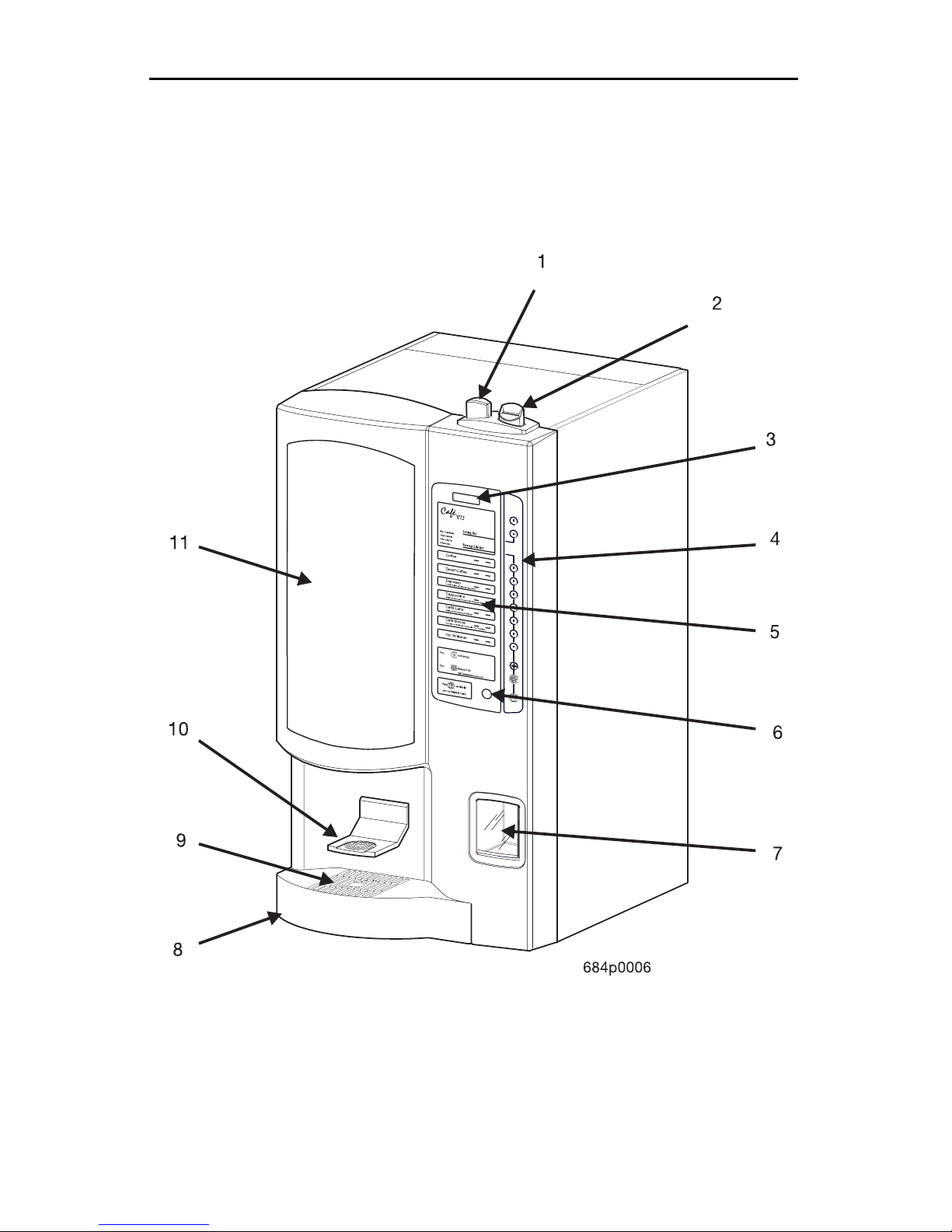
EXTERNAL VIEW
The it ems on the previous page are identified as follows:
ITEM
NUMBER
DEFINITION
1 Coin return butt on (optional)
2 Coin inser t (optional)
3 Message display
4 Selection and programming keypad
5 Drink selection menu
6 Carafe keyswitch
7 Coin return cup (optional )
8 Liquid drain tray
9 Carafe platform
10 Cup platform (swings back out of the way when using a carafe)
11 Point of purchas e photo display (optional)
6840070 Page 5
August, 2005
Café VII® Setup
12
11
7
13
7
7
7
1
2
3
4
7
7
7
10
8
9
INTERNAL VIEW
Page 6 6840070
5
6
684p0007
August, 2005

Café VII® Setup
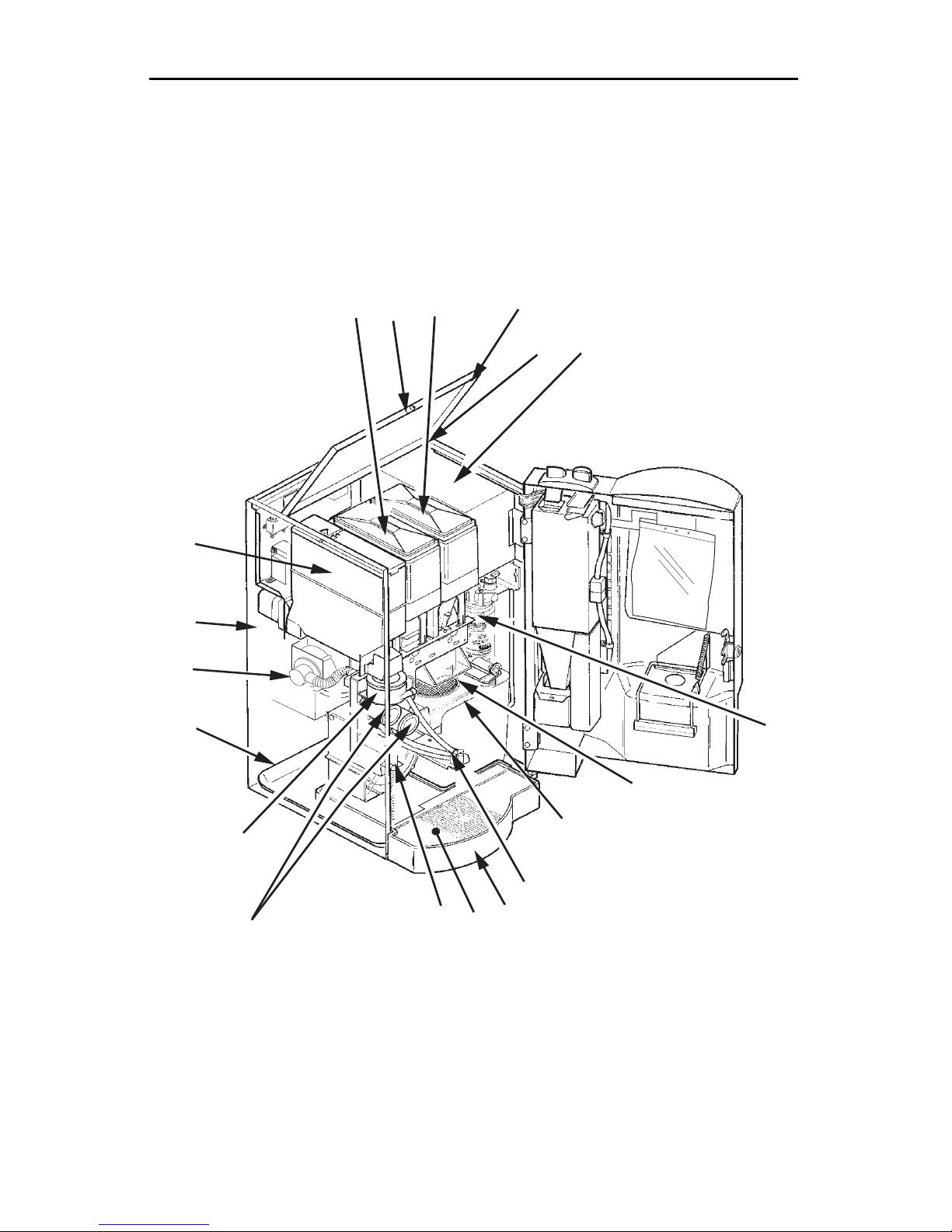
INTERNAL VIEW
The it ems on the previous page are identified as follows:
ITEM
NUMBER
1 Hinged lid (op ens for ea sy product loadin g)
2 Water valve and tank cover
3 6-function service keypad
4 Menu insert (rear side)
5 Plasti c zip lock parts bag
6 Coin mech (optional)
7 Door lock
8 Water filter assembly
9 Coin box
10 Brewer
11 Coff ee grounds pail
12 Dispensi ng nozzles
13 Door switch
14 Liquid dra in tray float and switc h
15 Filter paper roll
DEFINITION
16 Ingredient whippers
17 Filter paper housing
18 Mixing bo wl
19 Floor liner
20 Exhaust filter element
21 Exhaust s ystem blower
22 Chocolate ingredient canister
23 Main power switch
24 Primary controller PCB and EPR OM
25 Cabinet fan (optional)
26 Deca f canister
27 Coffee caniste r
6840070 Page 7
August, 2005

Café VII® Setup
SITE REQUIREMENTS
POWER SU PP LY
Ensure the machine has its own electrical circuit. NOTE - DOMESTIC UNITS The in ternal 4- amp fuse ONLY protects the electronics inside the machine. The
unit is provided with a 10 foot power cord and a polar ize d grounded plug. Use
only a polari zed grounded receptacle. Always follow national and local codes.
• Domestic and Canada ...........................115 VAC / 60 Hz - 15 Amp Circuit
• International...... ........ ................. ..........230 VAC / 50 Hz - 10 Amp Circuit
WATER SUPPLY
The best type of water for coffee brewing is normal tap water, filtered to remove
sediment, dirt, and chlorine. National Vendors recommends the Hyd r olife Brand
or the Everpure Brand - Model “OCS” filter products to provide the proper level
of filtration. If your location has chem ica lly softened water, do one of the fol
lowing:
-
• Install a non-softened water supply line to the machine location.
• Contact your local water filte r supplier for information and suggestions .
• Use a bottled water source with the optional electric wat er pump.
An easily accessible shut off valve up stream of the machine is highly recommended. This will simplify installation of the unit . Always follow national and
loca l codes.
WATER PRESS U RE
• Maximum water pressure ..................................................................80 PSI
• Minimum water pressure ...................................................................20 PSI
WASTE WATER
If the tray drain option is selected, proper pitch and air gap must be used. Always
follow local and national codes.
Page 8 6840070
August, 2005
Café VII® Setup
CLEARANCES
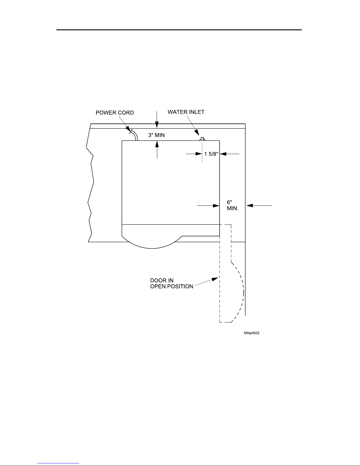
The power cord and water connections are on the back of the unit. Three (3)
inches of clearance is recommended at the back of the machine. Each side of the
unit should have at least six (6) inches of clearance. This will allow for key
access on one side and door swing on the other.
6840070 Page 9
August, 2005
Café VII® Setup
MACHINE INSTALLATION
To protect property and provide safety, installation should be
completed by pr ope rl y train ed pers onne l, and in accordan ce
with local and national codes.
This single cup brewer may be installed on a counter top or on the optional
factory supplied base. If the base option is used follow the instructions included
with it.
COUNTER TOP INSTALLATION
The unit prov ides three levels of cou nter top installation.
SET AND SEAL
Locate the unit, make the water connection, plug in the unit, and seal the coffee
maker to the counter top with the gasket provided.
Page 10 6840 070
August, 2005

Café VII® Setup
FASTEN AND SEAL
Before beginning this procedure verify both clearance and accessibility from
beneath the counter top.
Field Supplied Parts
Four (4) 5/16" thread-cutting screws.
Four (4) 5/16" flat washers.
Correct Screw Length
W ith the was her i ns talle d t he r emai ng thr ead wi ll equal the cou nter thic kness
plus 7/16".
Layout the machine location and mark locations of the four holes. Drill using a
1/2" bit. Secure the unit to the count er top with the thread-cuttng screws. Do not
overtighten, or the plastic nuts in the machine base may be stripped. (It may be
easier to co nnec t the water line before securing the unit to the counte r top.)
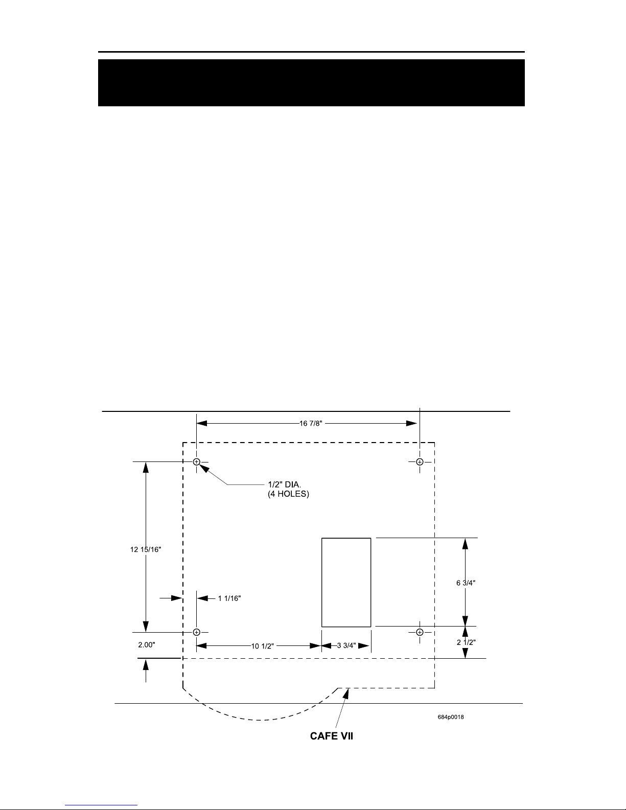
INSTALL AND SEAL
Before beginning this procedure verify both clearance and accessibility from
beneath the cou nter top. This option allows the use of a large waste grounds pail
located under the counter top. Remove the floor liner from the bottom of the
unit. Take out the two screws holding the cover plate. Cut a hole corresponding
to the openi ng in the bottom of the unit in the floor liner.
Field Supplied Parts
Four (4) 5/16" thread-cutting screws.
Four (4) 5/16" flat washers.
Correct Screw Length
W ith the was her i ns talle d t he r emai ng thr ead wi ll equal the cou nter thic kness
plus 7/16".
Layout t he m ac h ine locati on; then mark locations of the four fastenin g holes, and
a 3
3/4" by 6 3/4" cutout. Drill the holes using a 1/2" bit and make the cutout.
Secure the unit to the counter top with the thread-cuttng screws. Do not
overtighten, or the plastic nuts in the machine base may be stripped. (It may be
easier to co nnec t the water line before securing the unit to the counte r top.)
6840070 Page 11
August, 2005
Café VII® Setup
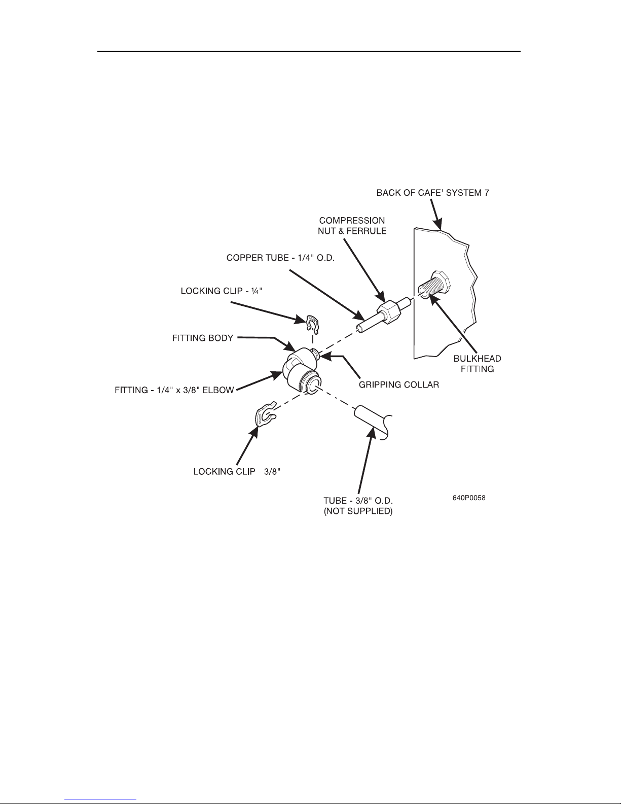
WATER LINE CONNECTIONS
FACTORY AND FIELD SUPPLIED PARTS
The water inlet on the unit comes from the factory with a 1/4" female
compression fitting. The factory also ship an addapter for use with a 3/8" line, as
illustrated below. All other components are field supplied. When code permits
the use of plastic tubing, use appropriate inserts at the connections to prevent
collapse..
FLUSHING LINES
Water lines should be flushed before connecting to the machine. This will
prevent sediment from entering the unit.
SEALING THE UNIT TO THE COUNTER TOP
FACTORY AND FIELD SUPPLIED PARTS
A sealing strip is supplied by the factory. Remove the paper back from a section
of the strip and apply to the base. Work a length at a time going completely
around the base of the unit. Seal must contact both the unit and the counter top.
No other parts are nee ded for this operation.
Page 12 6840 070
August, 2005
Café VII® Setup
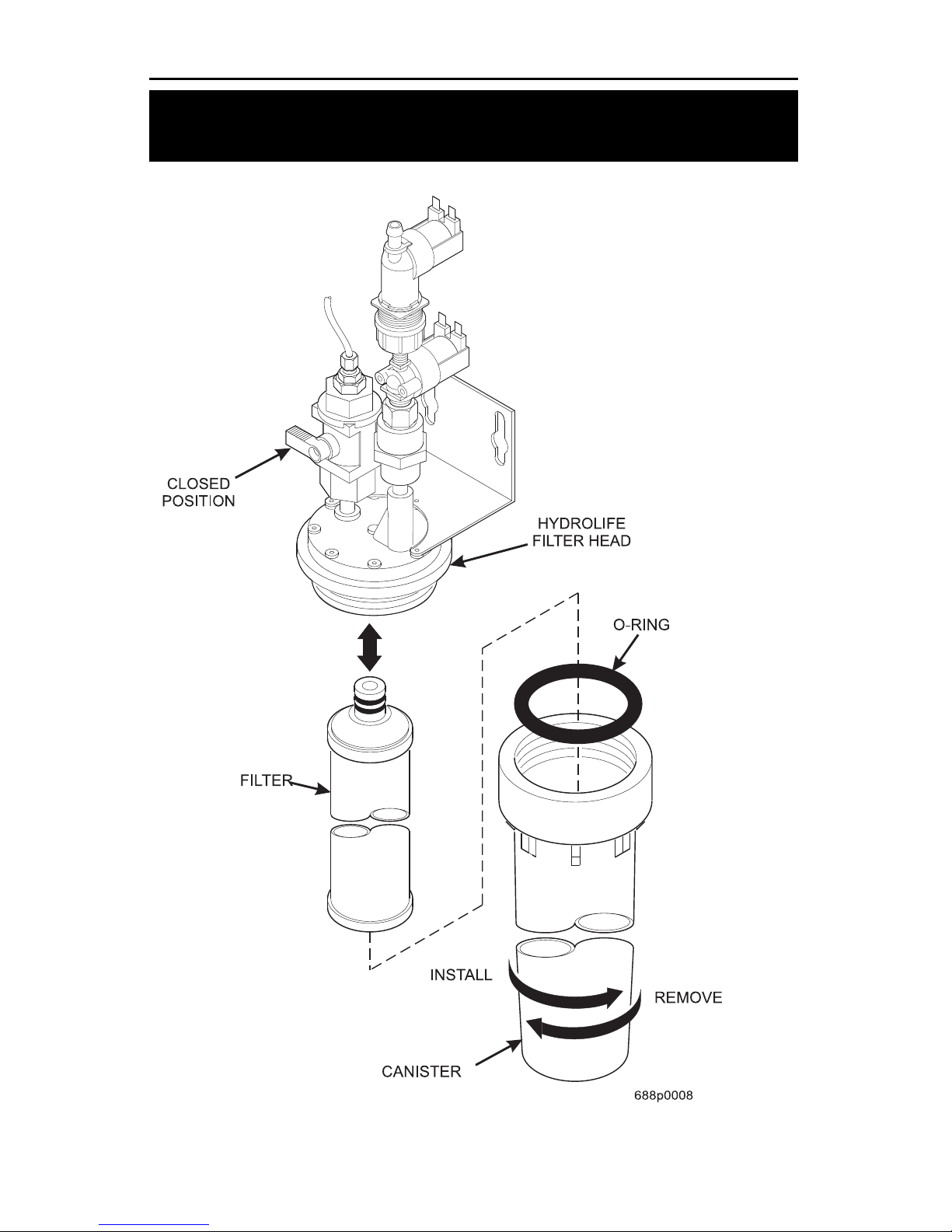
INSTALL WATER FILTER
HYDROLIFE BRAND...
6840070 Page 13
August, 2005
Café VII® Setup
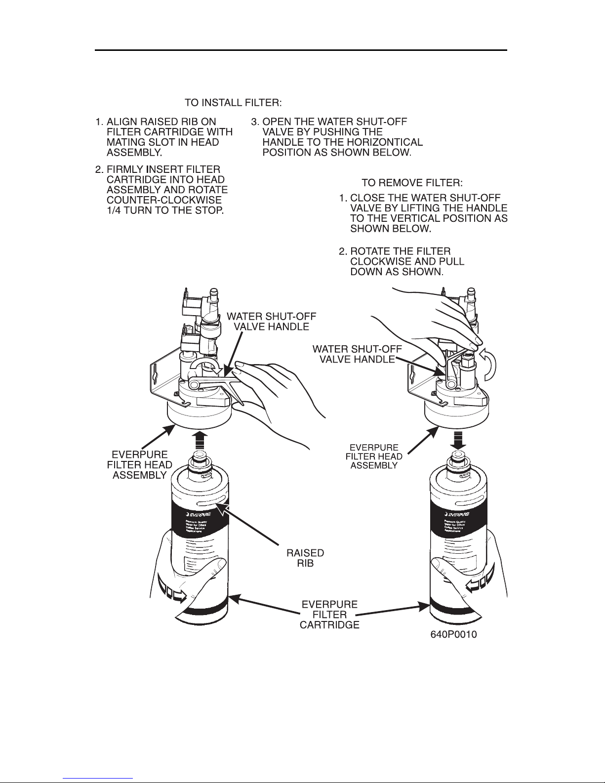
EVERPURE BRAND...
Page 14 6840 070
August, 2005
Café VII® Setup
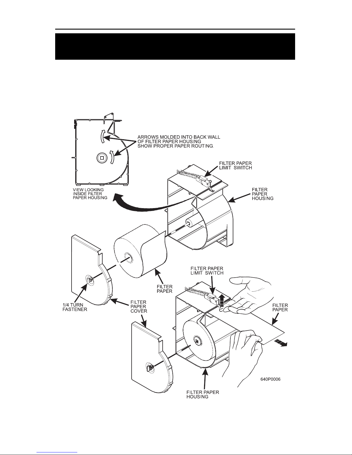
INSTALL FILTER PAPER
LOAD THE FILTER PAPER HOUSING...
1. Turn t h e fastener 1/4 turn counterclockwise and remove the filter paper cover.
2. Insert filter pape r in the filter paper hous ing as shown.
3. Feed the paper out of th e housing as shown by the arrows molded into the
back wall of the filter paper housing.
4. Lift up the li mit sw itch and feed the pape r past it as s hown. Rel ease the li mit
switch.
5. Replace the cover.
6840070 Page 15
August, 2005
Café VII® Setup
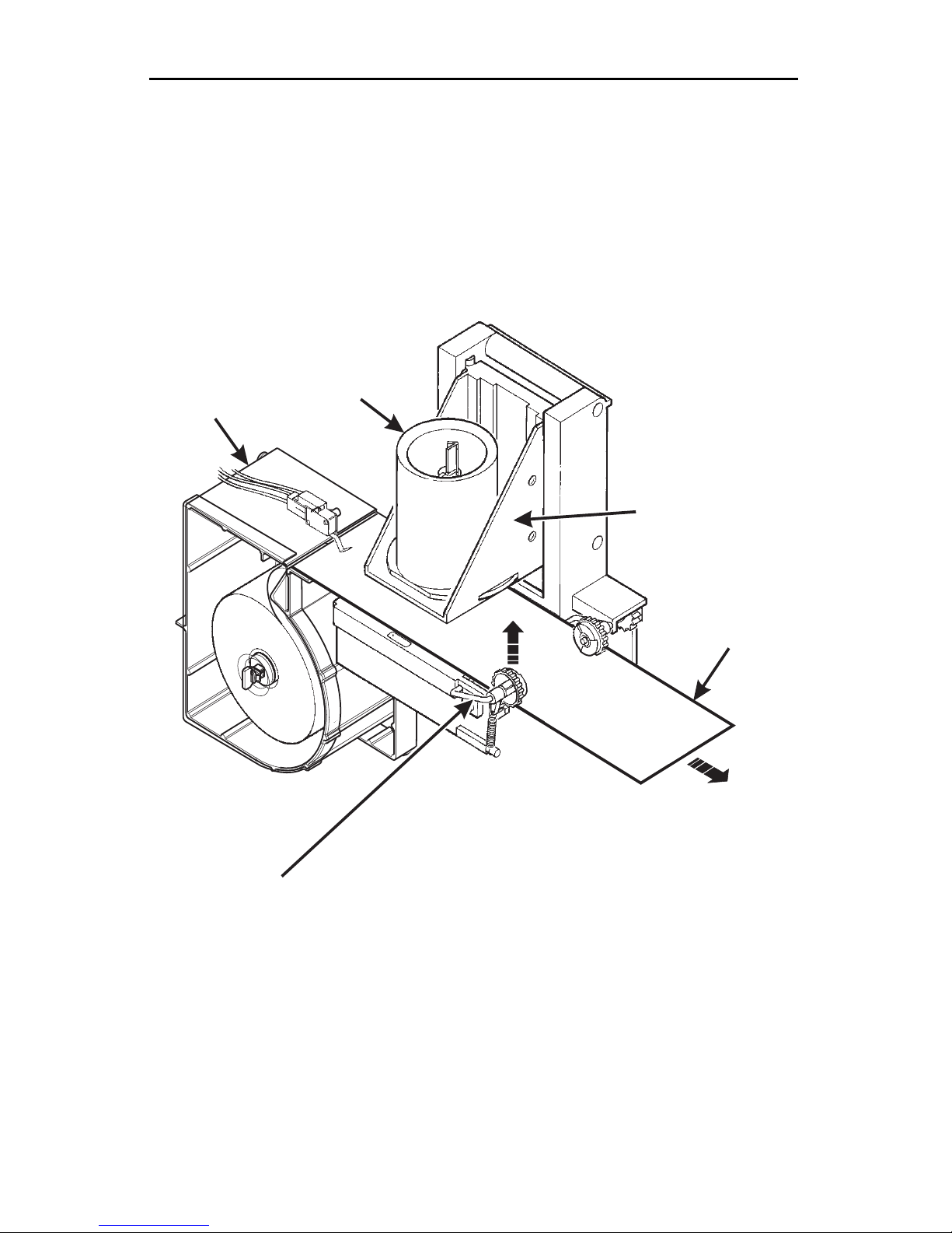
FEED PAPER THROUGH THE BREWER...
1. Hold the idler roller axle up out of the way as shown.
2. Route the paper under the brewer cylinder and the idler rollers.
3. Release the idler roller axle, capturing the filter paper.
4. Route the paper into the grounds bucket. For machines with base cabi nets
Feed filter pape r through the upper bucket into the lower grounds bucket.
BREWER
FILTER PAPER
HOUSING ASSY
CYLINDER
CYLINDER
CARRIER
IDLER
ROLLER
AXLE
FILTER
PAPER
640P0007
Page 16 6840 070
August, 2005

Café VII® Setup
SET UP THE COIN MECHANISM
(OPTIONAL)
NOTE
Only the following coin mechanisms will function with your
machine, and y our mach ine must be confi gured for the specifi c
type of coin mechanism you are using:
COINCO 9302-GX MDB
COINCO 9302-LF
COINCO USD-G701 MDB
CONLUX USLZ-001 MDB
MARS TRC6010-XV
MARS TRC6512 MDB
MARS V N45 1 0 MD B
LOADING THE COIN MECHANISM.
1. Open the cabinet door.
2. Insert coins into their respective tubes until each tube has been filled.
3. Inspect the tubes for shingled coins and corre ct if necessary.
6840070 Page 17
August, 2005
Café VII® Setup
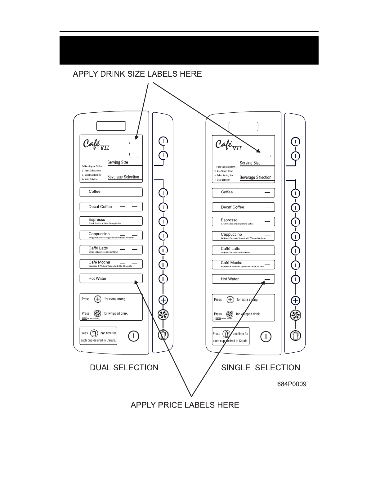
SET UP THE MENU INSERTS
Two sets of menu inserts are included with your machine. One set is used in
machines where two different drink sizes are av ailable; the other is us ed w h en
only one drink s ize is offered.
Page 18 6840 070
August, 2005
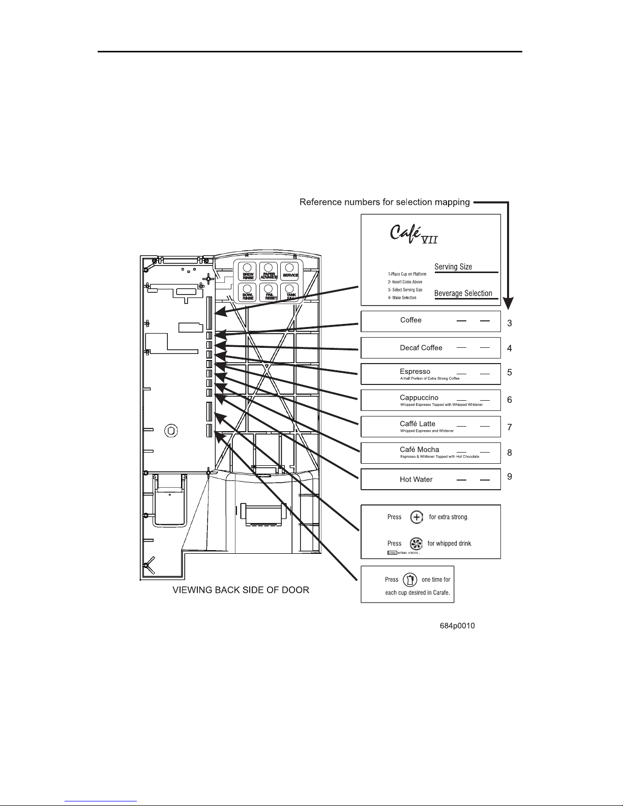
Café VII® Setup
This diagram shows you where each of the menu inserts are used. Blank inserts
are provided in the event that all selections are not sold. Refer to "Key Mapping/
Drin k Si z es " to ve r if y the order in w h ic h th ese ins e r ts will a p pe ar on the me n u .
NOTE: Shown as a two cup-size machine .
6840070 Page 19
August, 2005
Café VII® Setup
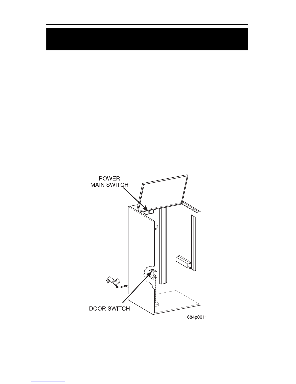
SWITCHES
DOOR SWITCH
The door switch has two positions:
DOOR OPEN Access to programming modes is provided when the door
is ope n .
DOOR CLOSED Machine returns to the vending mode.
MAIN POWER SWITCH
The main power switch turns off the m achine. The main power s w itch shoul d be
turned off when servicing any AC line voltage component.
WHEN SERVICING ANY COMPONENTS WITHIN
THE POWER PANE L ASSEMBLY, ALWAYS UNPLUG
THE MACHINE FRO M THE WALL RECEPTACLE
Page 20 6840 070
August, 2005
 Loading...