

Crane 3TSS1.38-45-36/210, 4TSC8-40-110/1000, 4TSC4-45-48/50, 4TSSC6-40-48/500, 4TSSC5.1-65-110/1000 User Manual
Page 1
TSS TSC TSSC series
Instruction for
installation, maintenance
and operation of
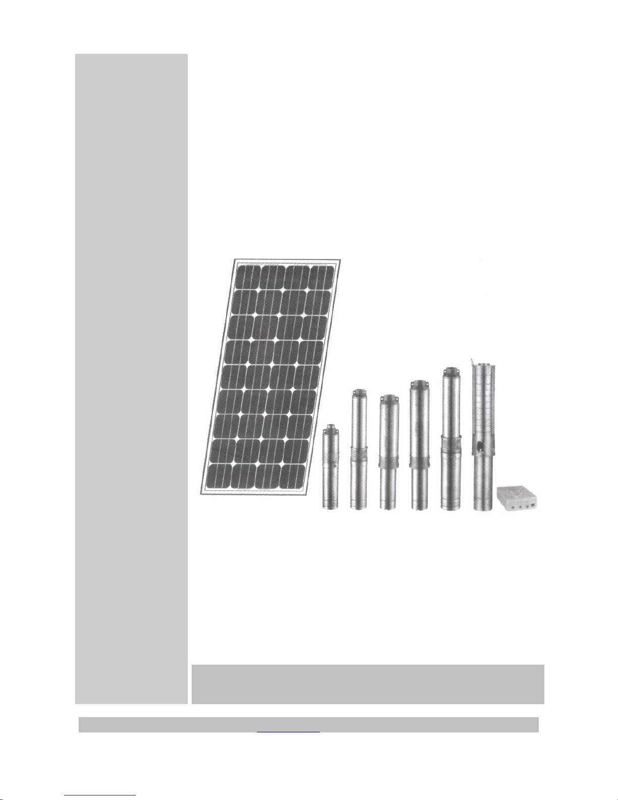
solar pump
Users' manual for solar pumps
series TSS, TSC и TSSC
Crane Ltd, Bulgaria, 4004 Plovdiv, 26 Komatevsko shose Str., phone +35932657578, fax +35932657580,
e-mail: office@crane-bg.com, www.crane-bg.com
Page 2

CONTENT
Version 1
I. Introduction
II. Important safety
instructions
III. Solar pumps' specification
IV. Guidelines for
installation and exploitation
of solar pumps
V. Indicators for operation and
fault instructions
VI. Cleaning and maintenance
of PV module
VII. Protection of the
environment
VIII. Contacts, warranty and
service maintenance
page 3
page 3
page 4
page 8
page 15
page 18
page 18
page 18
2
Page 3

I. Introduction
The Solar pumps allow you to extract water in areas, where aren't mains supplies, but with directly
transformation of solar energy into electricity.
Please read and apply herewith given instructions, so you can use the Cranes' solar pumps full
capacity. In case you don't observe them, this might result in personal injuries and product damages.
The present instructions are giving information about the safety measures, which should be undertaken
during the time of delivery and installation of the solar pumps, together with the technical instructions,
which should be followed while installing, mounting, wiring and maintaining.
Please keep these instructions during the whole service life of the solar pump. Read and observe very
carefully herewith given instructions.
The product warranty will be invalid if the written instructions for mounting and solar pump exploitation
are not complied with.
II. Important safety instructions
1. Strict observance of the installation instruction and solar pump exploitation are obligatory!
2. Do not use a part from the equipment or whole equipment set for activities which are not subject
of the exploitation instructions. Otherwise Crane Ltd or/and its representatives will not be held
under liability for damages, loss or injuries caused from the product to persons or movable and
non-movable property caused because of non-observation of the exploitation instructions
3. The right maintenance and exploitation ensure optimum result and long service life of the solar
pump.
4. Never instal the solar pomp on places in near vicinity of children or animals.
5. Do not use abrasive chemicals for cleaning of any part of this product.
3
Page 4
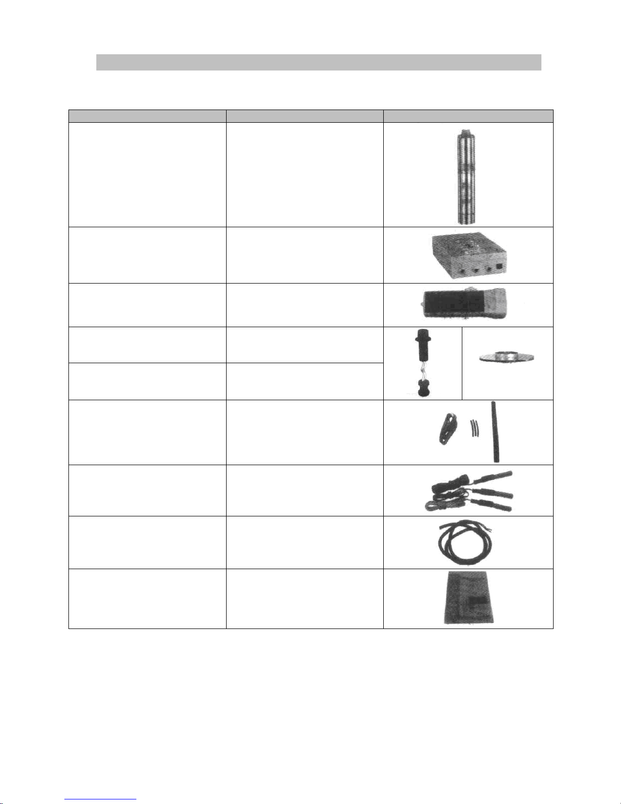
III. Solar pumps' specification
Type
Quantity
Picture
Submersible solar pump
1 piece
Controller 1 piece
Solar flashlight
1 piece
Screw (screw pump)
1 piece
Turbine (centrifugal pump,
plastic impeller)
1 piece
Insulation tape and thermal
shrink hose
3 pieces
Water lever sensors
3 pieces
Cable 2х1.5 mm
2
6 m
Manual 1 piece
4
Page 5
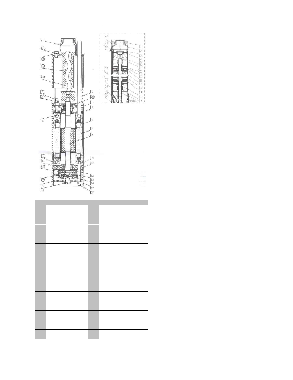
Water filled motor
№
Part
№
Part
1
Inlet area
15
Housing pump base
2
Outlet area
16
Plate pump base
3
Bearing nest
17
Adjustable nut
4
Cover
18
Screw bush
5
Bearing
19
Screw
6
Motor corps
(1)
Bolt
7
Stator
(2)
Spring washer
8
Rotor
(3)
Bolt
9
Cover
(4)
Hexagonal nut
10
Bearing nest
(5)
Key
11
Bearing
(6)
Spring washer
12
Plate
(7)
Hexagonal nut
13
Bearing nes water
lubricated
(8)
Heads' oil sealing
14
Bearing nest
(9)
Pins
5
Screw pump
Centrifugal pump
Page 6
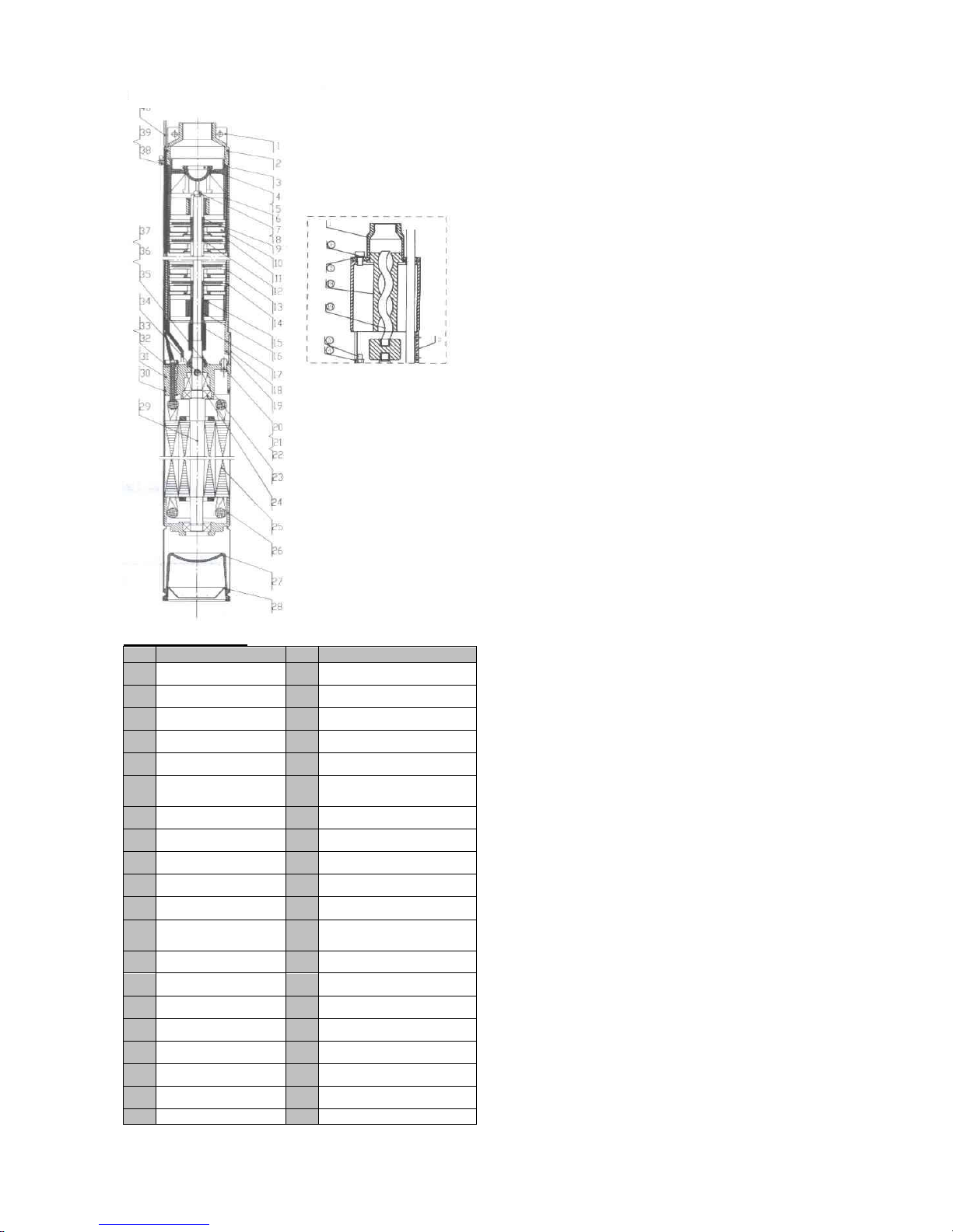
Water filled motor
№
Част
№
Част
1
Wire hole
21
Spring washer M8
2
O – ring
22
Nut M8
3
Valve housing
23
Mechanical seal
4
Valve
24
Ball bearing
5
O – ring
25
Stator
6
Limiting bearing
housing
26
Lower bearing housing
7
Nut
27
Rubber
8
Spring washer
28
Diaphragm
9
Washer
29
Working parts
10
Turbine
30
O - ring
11
Pomps' cover
31
Upper bearing housing
12
Rubber spring
washer
32
Plate
13
Pumps' corps
33
Cable bush
14
Motors' housing
34
Hollow pin
15
Limiting bearing
35
Anti-sand bush
16
Bearing bush
36
Anti-sand washer
17
Coupling
37
Washer
18
Cover
38
Washer
19
Nozzle
39
Bolt
20
Bolt M8х25
40
Cable
6
Centrifugal pump
Screw pump
Page 7
1. There is a three-phases brushless motor built in the pump, who directly drives a screw (for a
screw pump) or a turbine (for centrifugal pump) and has passed a special control test.
2. The motor is with simple and reliable construction, small volume and small weight.
3. The special double-plastic technology for motor encapsulating makes it suitable to be used
under water, as its insulation resistance exceeds 500 MegaOhms. The motors' bearings are
water-lubricated, which excludes a need of other lubricating materials (such as oils and
greases), which might be thrown in the water. This protects the environment.
4. The controller is especially designed to work with this type pumps, supplied trough photovoltaic
modules as it has built in МРРТ (maximum power point tracker), which moves the pannels
working point and as this extracts the maximal possible power. The built in protections from
short-cut, over-voltage and overheat protects the controller as well as the pump from damages.
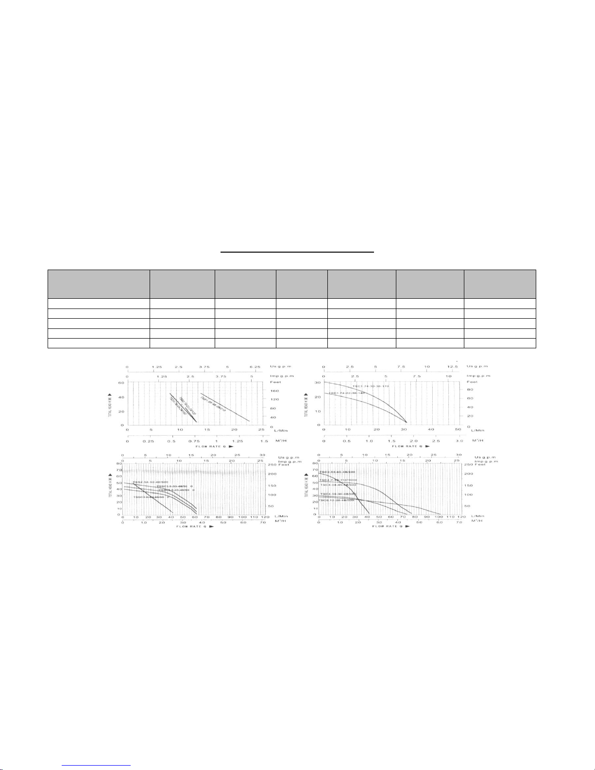
Technical characteristics
Type
Voltage
(V) DC
Power
(W)
Flow
(m3/h)
Maximal
displacement
(m)
Output
Pumps'
diameter
(mm)
3TSS1.38-45-36/210
36
210
1.38
45
¾”
76
4TSC4-45-48/500
48
500
4.00
45
1 ¼”
100
4TSC8-40-110/1000
110
1000
8.00
40
1 ¼”
100
4TSSC6-40-48/500
48
500
6.00
40
1 ¼”
100
4TSSC5.1-65-110/1000
110
1000
5.10
65
1 ¼”
100
7
Page 8

IV. Guidelines for installation and exploitation of solar pumps
Photovoltaic module (PV) selection
1. Operating principle:
The photovoltaic module converts the solar energy into electric energy (DC) → DC electric
energy enters into the controller → the controller stabilize the voltage, charges the accumulator
(option only for model 3TSS1,38) and produces voltage that conforms the pumps motor → the
pump extracts water
2. Solar pump system's advantages:
a. Much easier and more widely used than any other electrically driven pumps
b. Economic and environment friendly, because of renewable energy source usage.
3. Photovoltaic module(s) and accumulator selection
a. The PV module power is necessary to be selected in a way of being 30% or more than the
power consumed by the pump. The PV voltage must comply with the pumps' operating voltage
and the maximal voltage of the controllers' inlet.
b. The number of the accumulators used depends from the selection that we made about the
accumulators' voltage and the voltage of the pump. The voltage needed for a certain pump is
formed trough serial connection of the accumulators. The accumulators capacity should be
selected in accordance with the pumps' power and the time during which the accumulator can
supply the pump without being discharged under the threshold. It is not recommended to
connect accumulators in parallel connection to increase the total capacity, especially in
the cases when the accumulators are with different capacity!!!
Type
PV module
Solar pump
controler
V(DC)
Battery
Voltage
(V) DC
Power
(Wp)
Capacity
(Ah)/Voltage
(V)/Quantity
Connection
3TSS1.38-45-
36/210
36
210
1.38
100Аh / 12V / 3 бр.
Serial
* if 2 or more PV modules are to be connected – please pay attention about the way of the connection
A. If you connect 2 or more PV modules in series, the voltage in the 2 ends of the circuit will be equal to
the voltage of one module multiplied with the panels number, and the current will be equal to the current
of one module.
B. If you connect 2 or more PV modules in parallel, the current of the whole circuit will be equal to the
current of one module multiplied with the modules number, and the voltage will be equal to the voltage
of one module.
C. The connection of photovoltaic modules with different parameters is not recommended!!!
8
Photovoltaic module
Solar pump controler
Reservoir
Battery
Water pump
Page 9

INSTRUCTION FOR THE CONNECTION OF A CONTROLER FOR
SOLAR PUMP MODEL - 3TSS1.38-55-36/210
Cable terminal scheme
Mode selection
I: Mode photovoltaic panel
0: Switched off
II: Mode accumulator
Scheme and connection sequence
a). Open the package and check the controller for transport damages
b). Please set the switch in mode “switched off” position “0” before connection
c). Connect the controller as it is shown on picture 1
1. Connect the pump (be careful for the polarity U,V,W)
2. Connect the photovoltaic modules in series scheme to X+ and X-
3. Connect the accumulator to Y+ and Y-
4. Connect the level sensors to TC, TH, WC, WL, WH
9
Page 10

WARNING
1. After the first pump start, it will work about 2 minutes, then the controller will provide self-test for
about 30 seconds and will restart the pump.
2. If you wish full accumulator charge, please select mode “accumulator” position “II” and stop the
pumps' work (there are 2 possibilities of doing it:: 1> outer reservoir (if there is such) to be full'
2> to switch off the sensor of terminal WC.
3. Limit voltage values of open loop for photovoltaic modules:
Rated voltage (V)
Maximal voltage of open
loop (V)
Accumulators' voltage (V)
Maximal operating
current (A)
24V/36V
60V
24V,36V
12A
48V
100V
48V
12A
10
Page 11

INSTALATION INSTRUCTION OF SOLAR PUMPS
MODELS - 4TSC4-45-48/500 И 4TSSC6-40-48/500
Connection scheme
Lights indication:
POW led(green) – Switched on supply
RUN led (green/flashes green) – Motor working/Motor test
MPPT led (flashes green) – The system for working point set-up works
VOLT led (red) – The operating current is out of permissible limits
11
Controler for solar pump
Photovltaic module
Solar pump
Level sensors
Reservoir
Solar Pump
Page 12

CUR led (red) – The operating voltage is out of permissible limits
TANK led (red) – The reservoir is full
WL led (red) – The water level in the drilling is lower than WH sensor
Scheme names:
U;V;W – Motor pump
S+ – Photovoltaic module(+)
S- – Photovoltaic module(-)
WH – Heigh level sensor in the drilling
WL – Low level sensor in the drilling
COM1 – General sensors terminal in the drilling
TH – Level sensor in the reservoir
COM2 – General sensors terminal in the reservoir
ФВ1÷ФВ4 – Photovoltaic modules JLS72M170 (JLS72M160)
Connection sequence:
1. Open the package and check the controller for transport damages
2. Please set the switch in mode “switched off” position “0” before the connection
3. Connect the controller as it is shown on the picture:
ATTENTION! RISK FROM ELECTRIC SHOCK!
Connect the pump (pay attention for the polarity U,V,W)
Connect the photovoltaic module to S+ and S-
Connect the level sensors respectively to TC, TH, WC, WL, WH
WARNING
After the first pump start, it will work about 2 minutes, then the controller will provide self-test for about
30 seconds and will restart the pump.
12
Page 13

INSTALATION INSTRUCTION OF SOLAR PUMPS
MODELS - 4TSC8-40-110/1000 И 4TSSC5.1-65-110/1000
Connection scheme
Lights indication:
Power led(green) – Switched on supply
Run led (green) – Motor working
MPPT led (flashes) – The system for working point set-up works
13
Controler for solar pump
Solar pump
Photovltaic module
Level sensors
Reservoir
Solar Pump
Page 14

Err-I led (red) – The operating current is out of permissible limits
Err-V led (червен) – The operating voltage is out of permissible limits
Tank-F led (червен) – The reservoir is full
Well-l led (червен) – The water level in the drilling is lower
Scheme names:
1;2;3 – Motor pump
B+ – Photovoltaic module (+)
B- – Photovoltaic module (-)
ETH – Grounding
WH – Height level sensor in the drilling
WL – Low level sensor in the drilling
COM1 – General sensors terminal in the drilling
TH – Level sensor in the drilling
COM2 – General sensor terminal in the drilling
ФВ1÷ФВ5 – Photovoltaic modules CPV60M240
Connection sequence:
a). Open the package and check the controller for transport damages
b). Please set the switch in mode “switched off” position “0” before the connection
c). Connect the controller as it is shown on the picture:
ATTENTION! RISK FROM ELECTRIC SHOCK!
1. Connect the pump (pay attention for the polarity 1,2,3)
2. Connect the grounding cable to ETH
3. Connect the photovoltaic module to B+ and B-
Connect the level sensors respectively to TC, TH, WC, WL, WH
WARNING
After the first pump start, it will work about 2 minutes, then the controller will provide self-test for about
30 seconds and will restart the pump.
14
Page 15

Sequence of solar pumps installation
Open the package and check the product entirely
The control switch must be in position ”OFF” (“0” position)
Connect the photovoltaic module(s), accumulator (only if used in the relevan case), pump and
level sensors cables to the cable terminal of the controller in agreement with the connection
scheme. Choose the right cable dimension, fuses, switches and water level sensors.
Tight the fixing screws at the cable terminal with a screwdriver.
Be sure that the photovoltaic module(s) deliver power enough to the controller.
After finishing the upper steps, switch on the control switch (position I), the motor will operate for
10 seconds, after that will stop for 30 seconds (self-test), if the cables and the installation are
right, the pump will restart and work without interruption.
If the pump doesn't work properly, please check the operating indicators and the fault
indications, to find the reason and contact the supplier.
Mount the controller in a dry and well ventilated place. Never expose the controller in outer
atmospheric effect – the controler is not waterproof, and this will lead to its damage.
!!! Notes
The pump must be immersed in the water 15-20 minutes before its first starting. DO NOT
START THE PUMP DRY!, not even for test switching on. The working depth should not be
under 0,5m. It is not recommended the installation of the pump in depth bigger than 20m
under the water level.
During the installation of the submersible pump, there must be a rope connected to it.
Don't lift up the pump through the electric cable, the warranty will be refused if it gets
damaged.
The motors' supplying cables (U,V,W), must be connected to the controllers' cable
terminal (U,V,W) in the right way. Otherwise the motor will reverse and the pump will not
extract any water or very little water.
The water level sensor should be put over pumps' suction level. Otherwise it won't be
able to prevent the pump running dry. If there is no need of level sensor installation,
terminal WH and terminal WC (COM1) should be shortcut-connected.
You must make sure that the pump is positioned on the right depth. The stopping
between the switches ON and OFF should be at least 3 minutes or the pump protection
will be activated and the pump will stop working.
If there is a need of controllers' parameters change, the cover should be opened very
carefully to prevent the interruption of the inner connections.
15
Page 16

When a screw type solar pump will not be used for a long time, please take it out of the
water, wipe the housing and the screw and oil the pump housing with vegetable oil.
The regulating bolt at the base is already set by the quality control before the delivery.
The turning of this bolt by the customer might cause defects, degradation or low
efficiency.
The submersible pumps can be used only in waters with sands less than 0.1%.
The supplying cables cross section shouldn't be less than 2.5 mm2. It should be chosen
in agreement with the cable length and the pumps' capacity.
The pumps' supplying cable can be elongated depending the working deep, as the
connection place should be very well insulated to prevent a shortcut danger and damage
in the controller. The connection and insulation method is shown on picture 1, page 16.
Peel the outer cable covering as well as the covering of the separate wires, as they
should be cut in different length as it is shown on the picture. Connect the three wires,
tight the connections with thinner not insulated wire and weld the connections. Every
separate connection should be insulated with thermal shrink hose. The three
connections are tightly twined with insulation tape and over the tape is put thermal
shrink hose. Make sure that the thermal hose is well stuck and water can not enter from
anywhere. Finally join the three wires to the controllers' terminal as observing the
polarity (U,V,W).
V. Indicators for operation and fault instructions
Indications
Possible reason
Solution
Indication for
supply not
lighted
No supply
Switch on supply key
The connection is wrong or not tight
Check and tight all connections
The controller, photovoltaic module or
battery are damaged
Contact the supplier or the service
Fault indication
lighted
The wires cross section is less than
1.5 mm
2
Choose wires with bigger cross section
than 1.5 mm
2
Motors' rotor is blocked
Clean the pump
Solar radiation intensity is not enough
Wait until solar radiation intensity
increases or correct the module situation
The water level is over the
permissible limit
Correct the pump situation
Indications for
level and fault
lighted
The water level is within
impermissible limits
Wait until the water level raises or
correct the pump situation
There is no water level sensor
Mount the water level sensors in
agreement with the instruction or
connect terminal WH to WC (only if
sensors mounting is not required)
!!! Notes
1. Important for water level sensors:
If the pump works over the water level, there is a danger of pump damage (the warranty is invalid).
16
Page 17

The level sensors' target is to protect the pump from running dry while monitoring the water level and if
necessary sending a signal to the controller to switch off the pump.
The level sensors are three probes from a stainless steel. The probe should not be covered or to
touch conductible parts, so it can work properly.
If it is necessary to elongate the probes' cable, the cable which will be used must be with
suitable cross section, the connection should be welded and insulated with insulating tape and
thermal shrink hose.
2. Level sensors installation:
The cables of the three probes of level sensors must be connected to WH, WL and WC separately.
“WH” probe is installed in upper position to detect the water level in which the pump shoul start if it was
stopped because of water level fall. “WL” probe is installed just over the pump, to detect the water level
where the pump wouldn't run dry. “WC” probe /common point/ is to be installed under the pump level.
Level sensors' working range is between probe “WH” and probe “WL”. When the water level is
lower than probe “WL”, the pump motor will stop working. When the water level raises up to
probe “WH”, the pump motor will start working again. Be careful for the distance between WH and
WL, it must be selected in such way, that the water level to raise for not less than 3 minutes.
17
1. cable
2. 0,5 mm2 bare copper wire
3. coupleable rubber tape
4. plastic insulating tape
Page 18

picture 1
18
Page 19

VI. Cleaning and maintenance of PV module
Crane Ltd modules are manufactured as this to have prolonged service life and require minimal
maintenance.
You should regularly remove accumulated dirt from the PV module(s) (eg dust, pollen,
vegetation, bird droppings, etc.). Such contamination, which overshadows the modules' active
areas can lead to limitation of system performance and decrease the solar pump production.
Please obcerve the following points:
For PV module(s) cleaning use water and soft sponge.
Avoid the water cleaning, when there is a danger of freezing of big temperature
differences between the module, the water and the air.
Hard water used for the cleaning, must be descaler in advance, so the remaining traces
to be avoided. Remove the remaining water from the module.
Do not use abrasive cleaning materials or surface-active agents (eg. Soap). Do
not scrap the contaminations. This might damage the modules' surface.
VII. Protection of the environment
After the service life termination of the solar pump, do not dispose it with normal
household waste, but transmit it to a collection point for waste recycling. This will
help protect the environment.
VIII. Contacts, warranty and service maintenance
Контакти
Contacts
Crane Ltd.
Bulgaria
4004, Plovdiv, 26 Komatevsko shose Str.
Phone: +35932657578
Fax: +35932657580
e-mail: office@crane-bg.com
web: www.crane-bg.com
Warranty conditions
The imported Crane Ltd. guarantee that the product will remain without defects in material and
manufacture for 3 (three) years from the date of delivery.
In case where Crane Ltd establish a defect as a result of the material or manufacture, may at its
assessment, repair the product or deliver new one – in terms EXW Plovdiv, Bulgaria.
19
Page 20

The warranty is not valid in cases when:
The product is damaged by abuse.
Damage due improper installation or connection to improper voltage.
Transportation or movement of the product in improper conditions.
In case the product has been maintained by person who is not authorised from the
manufacturer of the provider
If you do not represent the warranty card and the Invoice when making the claim. The
claim can be applied only when all necessary documents are available.
20
Page 21

WARRANTY CARD
Client: __________________________________________________________________________
Address: ________________________________________________________________________
________________________________________________________________________________
Phone: _________________________________________________________________________
Fax: ____________________________________________________________________________
Mobile phone: ____________________________________________________________________
Model: ___________________________________________________________________________
Product №: ______________________________________________________________________
Bought day: ______________________________________________________________________
Note: ___________________________________________________________________________
_________________________________________________________________________________
Since the Order date, we give 3 years of warranty
for repair with the following conditions:
Warranty conditions:
1. The importer Crane Ltd. guarantee that the solar pumps will remain without defects in
material and manufacture for 3 (three) years from the data of delivery..
2. In case where Crane Ltd establish a defect as a result of the material or manufacture,
may at its discretion, repair the product or deliver new one – in terms EXW Plovdiv,
Bulgaria.
3. The warranty is not valid in cases when:
* The product is damaged by abuse
* Damage due improper installation or connection to improper voltage
* Transportation or movement of the product in improper conditions
* In case the product has been maintained by person who is not authorised from the
manufacturer of the provider
If you do not represent the warranty card and the Invoice when making the claim. The claim can be
applied only when all necessary documents are available
IMPORTANT INSTRUCTIONS
Solar panel position:
As we use the electric energy from photovoltaic pannels for the solar pump supply, is
necessary the right solar pannel orientation regarding the sun. The photovoltaic module have
highest performance when the solar energy falls perpendicularly regarding the pannels' surface.
Every shading guides to photovoltaic pannel performance decrease, and there from, to
decrease of the pumped out water flow.
Submitted: Crane Ltd. Received: ............................................
................................................... ...............................................
.................................................. ...............................................
Crane Ltd, Bulgaria, 4004 Plovdiv, 26, Komatevsko shose Str., phone +35932657578, fax +35932657580,
e-mail: office@crane-bg.com, www.crane-bg.com
 Loading...