

Page 1
®
BARNES
INSTALLATION and OPERATION MANUAL
Solids Handling Submersible Pump
18 Frame
3SHV
Vortex Pumps
5 - 10HP, 3450RPM
2 - 7.5HP, 1750RPM
3SHM
Monovane Pumps
2 - 7.5HP, 1750RPM
4SHV
Vortex Pumps
2 - 10HP, 1750RPM
4SHM
Monovane Pumps
3 - 10HP, 1750RPM
4SHD
Dual Vane Pumps
3 - 10HP, 1750RPM
IMPORTANT! Read all instructions in this manual before operating pump.
As a result of Crane Pumps & Systems, Inc., constant product improvement program,
product changes may occur. As such Crane Pumps & Systems reserves the right to
change product without prior written noti• cation.
A Crane Co. Company
420 Third Street 83 West Drive, Bramton
Piqua, Ohio 45356 Ontario, Canada L6T 2J6
Phone: (937) 778-8947 Phone: (905) 457-6223
Fax: (937) 773-7157 Fax: (905) 457-2650
www.cranepumps.com
This product may be covered by one or more of the following patents
and other patent(s) pending: US Patent 7,931,473 & 8,128,360
Form No. 133030-Rev. Q
Page 2

TABLE OF CONTENTS
SAFETY FIRST ...........................................................................................................................3
A. PUMP SPECIFICATIONS ................................................................................................... 4 - 13
B. GENERAL INFORMATION ....................................................................................................... 14
C. INSTALLATION ................................................................................................................. 14 - 27
ELECTRICAL DATA ........................................................................................................... 16 - 27
D. START-UP OPERATION ................................................................................................... 27 - 28
E. PREVENTATIVE MAINTENANCE .............................................................................................28
F. SERVICE and REPAIR ...................................................................................................... 28 - 29
G. REPLACEMENT PARTS ...........................................................................................................30
TROUBLE SHOOTING ..............................................................................................................31
SH - CROSS-SECTIONS, (Fig. 9 & 10) & EXPLODED VIEWS, (Fig. 11) ......................... 32 - 33
PARTS LISTS AND KITS .................................................................................................. 34 - 43
WARRANTY ..............................................................................................................................45
RETURNED GOODS POLICY ................................................................................................. 46
WARRANTY REGISTRATION .................................................................................................. 46
START-UP REPORT ........................................................................................................ 47 - 48
Other brand and product names are trademarks or registered trademarks of their respective holders.
® Barnes is a registered trademark of Crane Pumps & Systems, Inc
1995,1997,1998,1/2004, 4/05
, 1/06, 3/06, 9/06, 12/06, 2/07 Alteration Rights Reserved
2
Page 3
SAFETY FIRST!
Please Read This Before Installing Or Operating Pump.
This information is provided for SAFETY and to PREVENT
EQUIPMENT PROBLEMS. To help recognize this information,
observe the following symbols:
Do not block or restrict discharge hose, as discharge
hose may whip under pressure.
IMPORTANT! Warns about hazards that can result
in personal injury or Indicates factors concerned with
assembly, installation, operation, or maintenance which
could result in damage to the machine or equipment if
ignored.
CAUTION ! Warns about hazards that can or will cause minor
personal injury or property damage if ignored. Used with symbols
below.
WARNING ! Warns about hazards that can or will cause serious
personal injury, death, or major property damage if ignored. Used
with symbols below.
Hazardous fl uids can
cause fi re or explosions, burns or death
could result.
Biohazard can cause
serious personal injury.
Rotating machinery
Amputation or severe
laceration can result.
Only qualifi ed personnel should install, operate and repair
pump. Any wiring of pumps should be performed by a qualifi ed
electrician.
WARNING ! - To reduce risk of electrical shock, pumps
and control panels must be properly grounded in
accordance with the National Electric Code (NEC) or the
Canadian Electrical Code (CEC) and all applicable state,
province, local codes and ordinances.
WARNING! - To reduce risk of electrical shock, always
disconnect the pump from the power source before
handling or servicing. Lock out power and tag.
WARNING! Operation against a
closed discharge valve will cause
premature bearing and seal failure on
any pump, and on end suction and
self priming pump the heat build may cause the generation of
steam with resulting dangerous pressures. It is recommended
that a high case temperature switch or pressure relief valve be
installed on the pump body.
CAUTION ! Never operate a pump with a plug-in type
power cord without a ground fault circuit interrupter.
CAUTION! Pumps build up heat and
pressure during operation-allow time
for pumps to cool before handling or
servicing.
WARNING! - DO NOT pump hazardous materials
(fl ammable, caustic, etc.) unless the pump is specifi cally
designed and designated to handle them.
Hazardous fl uids can Hazardous
pressure, eruptions or explosions
could cause personal injury or
property damage.
Hazardous voltage can shock,
burn or cause death.
Extremely hot Severe burnes can
occur on contact.
WARNING! - DO NOT wear loose clothing that may
become entangled in the impeller or other moving parts.
WARNING! - Keep clear of suction and discharge
openings. DO NOT insert fi ngers in pump with power
connected.
Always wear eye protection when working on pumps.
Make sure lifting handles are securely fastened each
time before lifting. DO NOT operate pump without
safety devices in place. Always replace safety devices
that have been removed during service or repair.
Secure the pump in its operating position so it can not
tip over, fall or slide.
DO NOT exceed manufacturers recommendation for
maximum performance, as this could cause the motor
to overheat.
DO NOT remove cord and strain relief. Do not connect
conduit to pump.
WARNING! Cable should be protected at all times to
avoid punctures, cut, bruises and abrasions - inspect
frequently. Never handle connected power cords with
wet hands.
WARNING! To reduce risk of electrical shock, all wiring
and junction connections should be made per the NEC
or CEC and applicable state or province and local
codes. Requirements may vary depending on usage
and location.
WARNING! Submersible Pumps are not approved for
use in swimming pools, recreational water installations,
decorative fountains or any installation where human
contact with the pumped fl uid is common.
WARNING! Products Returned Must Be Cleaned,
Sanitized, Or Decontaminated As Necessary Prior
To Shipment, To Insure That Employees Will Not Be
Exposed To Health Hazards In Handling Said Material.
All Applicable Laws And Regulations Shall Apply.
Bronze/brass and bronze/brass fi tted pumps may
contain lead levels higher than considered safe for
potable water systems. Lead is known to cause cancer
and birth defects or other reproductive harm. Various
government agencies have determined that leaded
copper alloys should not be used in potable water
applications. For non-leaded copper alloy materials of
construction, please contact factory.
IMPORTANT! - Crane Pumps & Systems, Inc. is not
responsible for losses, injury, or death resulting from a
failure to observe these safety precautions, misuse or
abuse of pumps or equipment.
3
Page 4
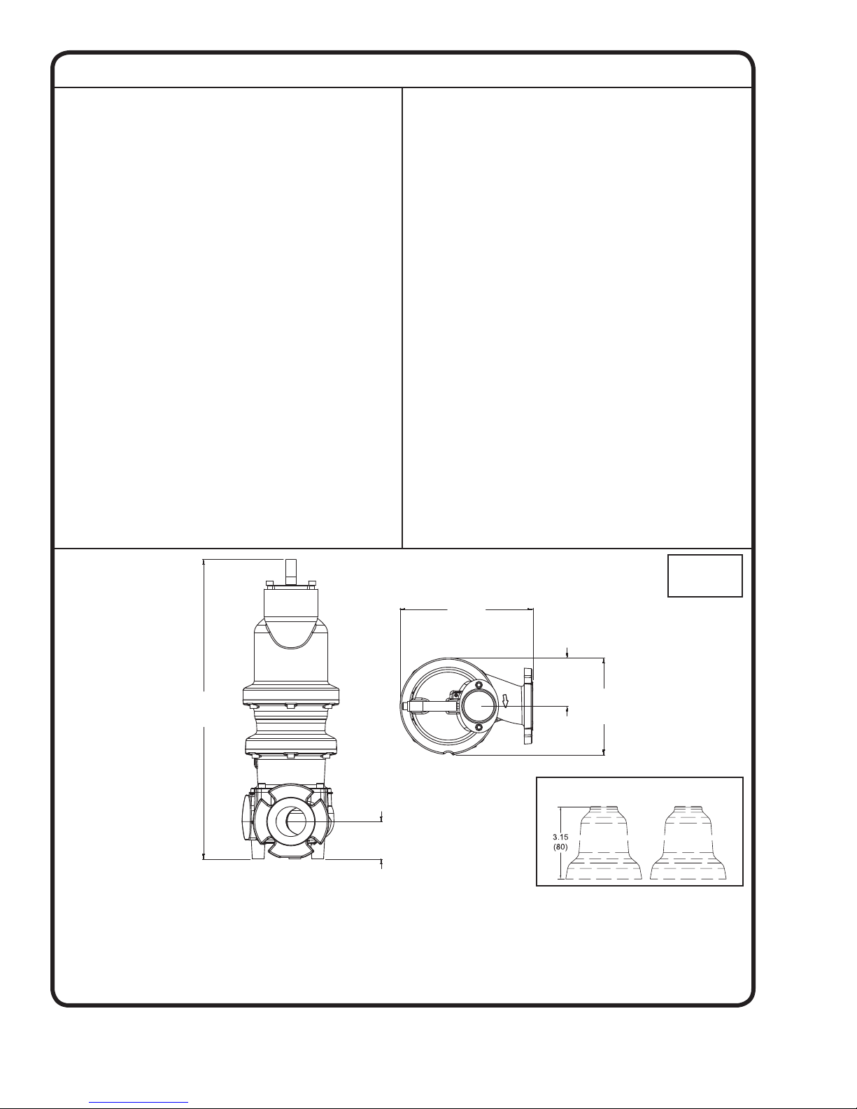
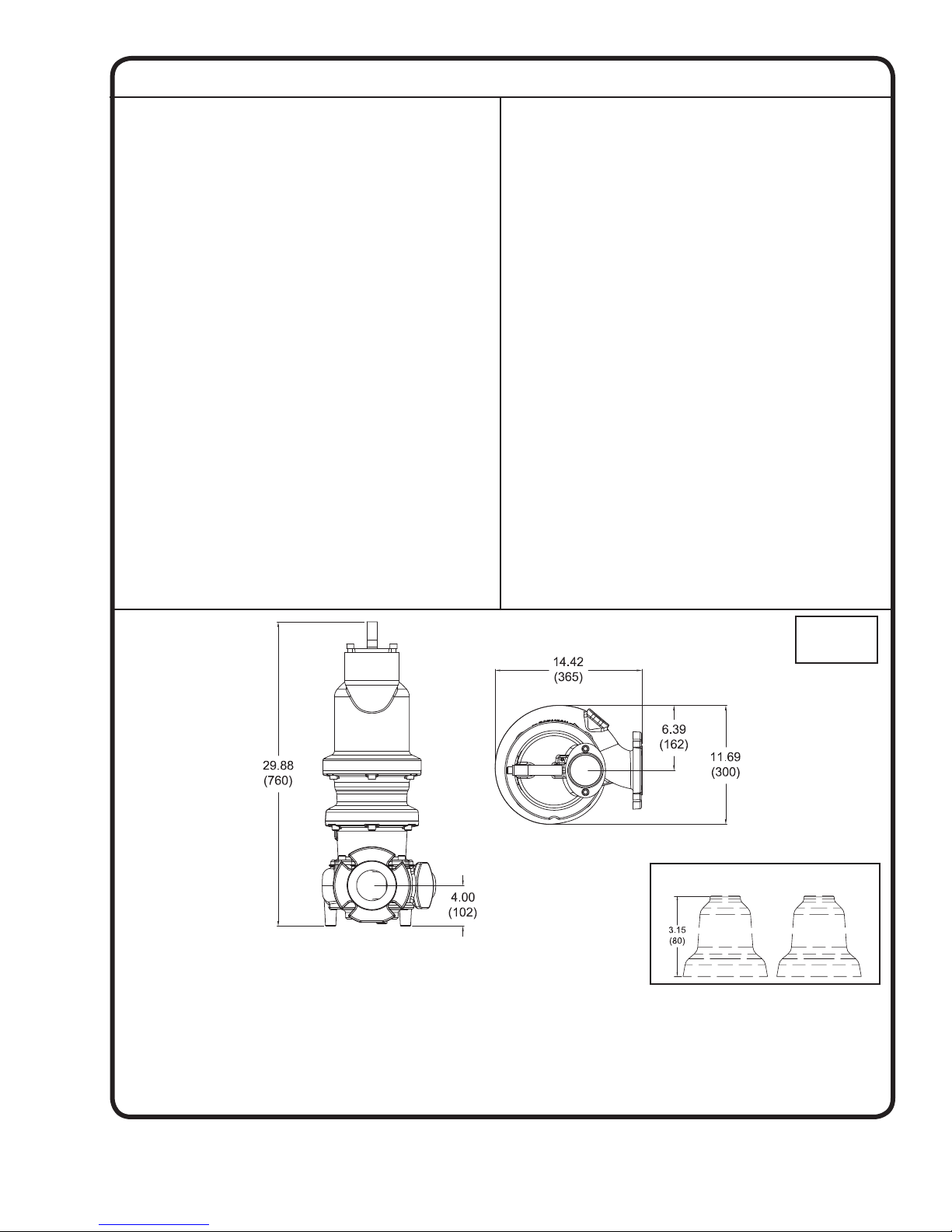
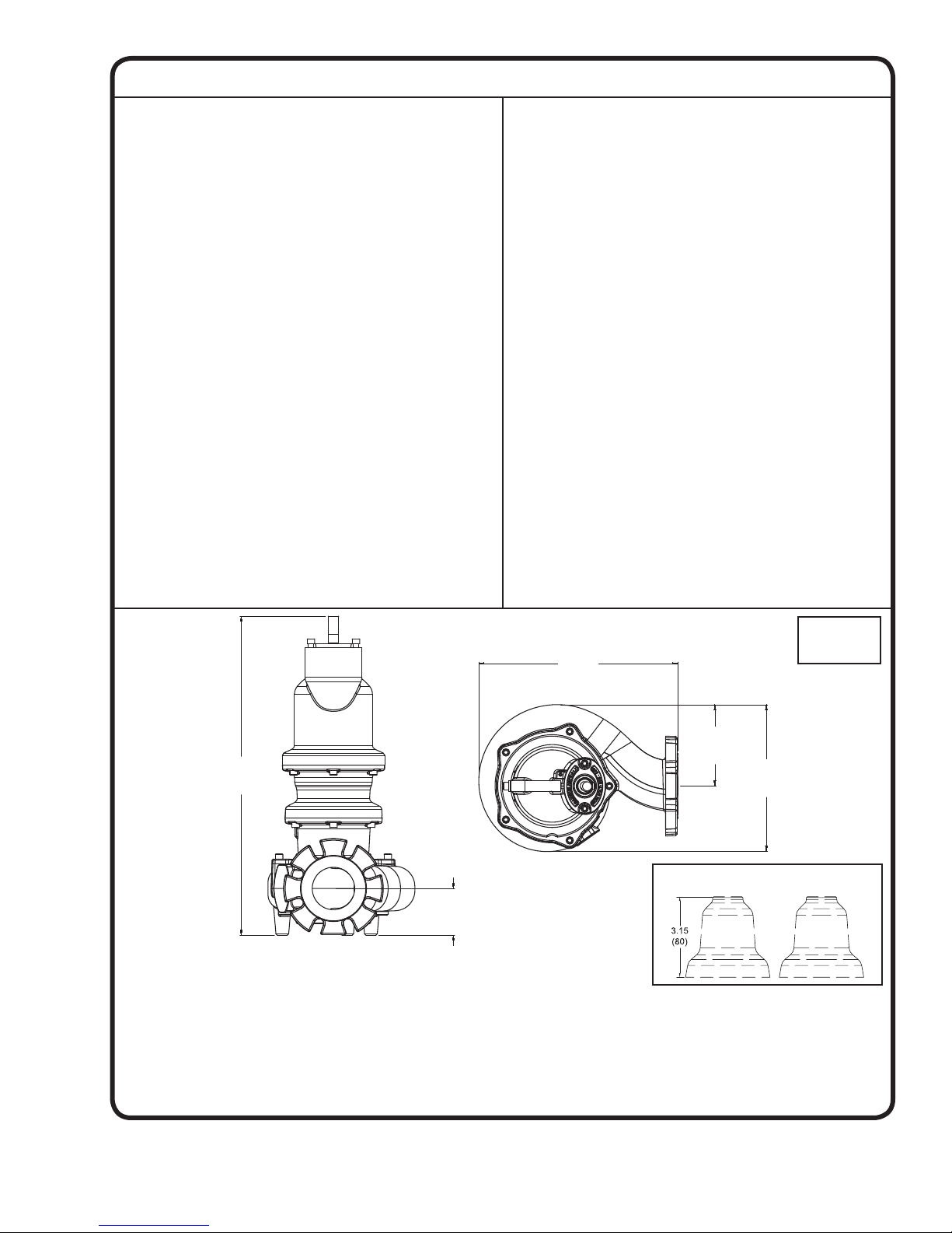
SECTION: A - PUMP SPECIFICATIONS: 3SHVR (Vortex) Pump Models
30.05
(763)
13.33
(339)
9.74
(247)
4.84
(123)
3.76
(96)
DISCHARGE ......................3”, 125 lb. Horizontal Flange
Slotted to accomodate 80mm
ISO Flanges
LIQUID TEMPERATURE ... 104°F (40°C) Continuous
VOLUTE ............................. Cast Iron ASTM A-48, Class 30
WEAR RING ........................C954 Lead-Free Bronze
MOTOR HOUSING .............Cast Iron ASTM A-48, Class 30
SEAL PLATE ......................Cast Iron ASTM A-48, Class 30
IMPELLER:
Design ....................Vortex, With Pump Out
Vanes on Back Side. Dynamically
Balanced ISO G6.3
Material ................. Ductile Iron ASTM A-536, 65-45-12
SHAFT ...............................416 Stainless Steel
“O” RINGS .......................... Buna-N
HARDWARE .......................300 Series Stainless Steel
LIFTING BAIL .....................300 Series Stainless Steel
PAINT ...............................Epoxy Dupont Corlar® Amine
Epoxy, Two Coats
SEAL: Design ...................Tandem Mechanical, Oil Filled
Reservoir.
Material: Inboard....Rotating Face - Carbon
Stationary Face - Ceramic
Material: Outboard . Rotating Face - Silicon Carbide
Stationary Face - Silicon Carbide
Elastomer - Buna-N (Both Seals)
Hardware - 300 Series Stainless
(Both Seals)
CORD ENTRY ..................... Custom Molded, Quick Connected
for Sealing and Strain Relief
POWER CORD ...................CSA Certifi ed Submersible Power
Cable 2000V - Ordered Separately
SPEED ............................... 3450 RPM (Nominal)
UPPER BEARING:
Design ....................Single Row, Ball, Oil Lubricated
Load ...................... Radial
LOWER BEARING:
Design .....................Double Row, Ball, Oil Lubricated
Load ....................... Radial & Thrust
MOTOR: Design ................. NEMA B Three Phase Torque Curve.
Oil-Filled, Squirrel Cage Induction,
Inverter duty rated per NEMA
MG-1 part 31
Insulation ..............Class H, Varnish & Magnet Wire
SINGLE PHASE ................Dual Voltage 208-230V, 2, 3, 5HP.
Requires Overload Protection to be
included in control panel.
THREE PHASE .................Tri-voltage 208-230/460V & 575V,
2J thru 10HP. Requires Overload
Protection to be included in control
panel.
MOISTURE SENSOR .......Normally Open (N/O) with 330
K-Ohm Test Resistor Across
Probes. Requires Relay in
Control Panel
TEMPERATURE SENSOR ..Three Normally Closed (N/C).
To be wired in series with
contactor control circuit
OPTIONAL EQUIPMENT ..Seal Material, Impeller Trims,
Cord Length, Leg Kit (p/n 125506)
MARKINGS .......................CSA, CE
WEIGHT ............................199 Pounds (90 Kg)
NOISE EMISSION MAX ....In-Air 65 dB-A
SUBMERGENCE ..............Max Depth 66ft (20m)
Dimensions
inches (mm)
Optional Leg Kit - p/n 125506
IMPORTANT !
1.) MOISTURE AND TEMPERATURE SENSORS MUST BE CONNECTED TO VALIDATE THE CSA LISTING.
2.) A SPECIAL MOISTURE SENSOR RELAY IS REQUIRED IN THE CONTROL PANEL FOR PROPER OPERATION OF THE MOISTURE SENSORS.
CONTACT BARNES PUMPS FOR INFORMATION CONCERNING MOISTURE SENSING RELAYS FOR CUSTOMER SUPPLIED CONTROL PANELS.
3.) THESE PUMPS ARE CSA LISTED FOR PUMPING WATER AND WASTEWATER. DO NOT USE TO PUMP FLAMMABLE LIQUIDS.
4.) INSTALLATIONS SUCH AS DECORATIVE FOUNTAINS OR WATER FEATURES PROVIDED FOR VISUAL ENJOYMENT MUST BE INSTALLED IN
ACCORDANCE WITH THE NATIONAL ELECTRIC CODE ANSI/NFPA 70 AND/OR THE AUTHORITY HAVING JURISDICTION. THIS PUMP IS NOT
INTENDED FOR USE IN SWIMMING POOLS, RECREATIONAL WATER PARKS, OR INSTALLATIONS IN WHICH HUMAN CONTACT WITH PUMPED
MEDIA IS A COMMON OCCURRENCE.
5.) THIS PUMP IS NOT APPROPRIATE FOR THOSE APPLICATIONS SPECIFIED AS CLASS 1 DIVISION 1 HAZARDOUS LOCATIONS.
4
Page 5

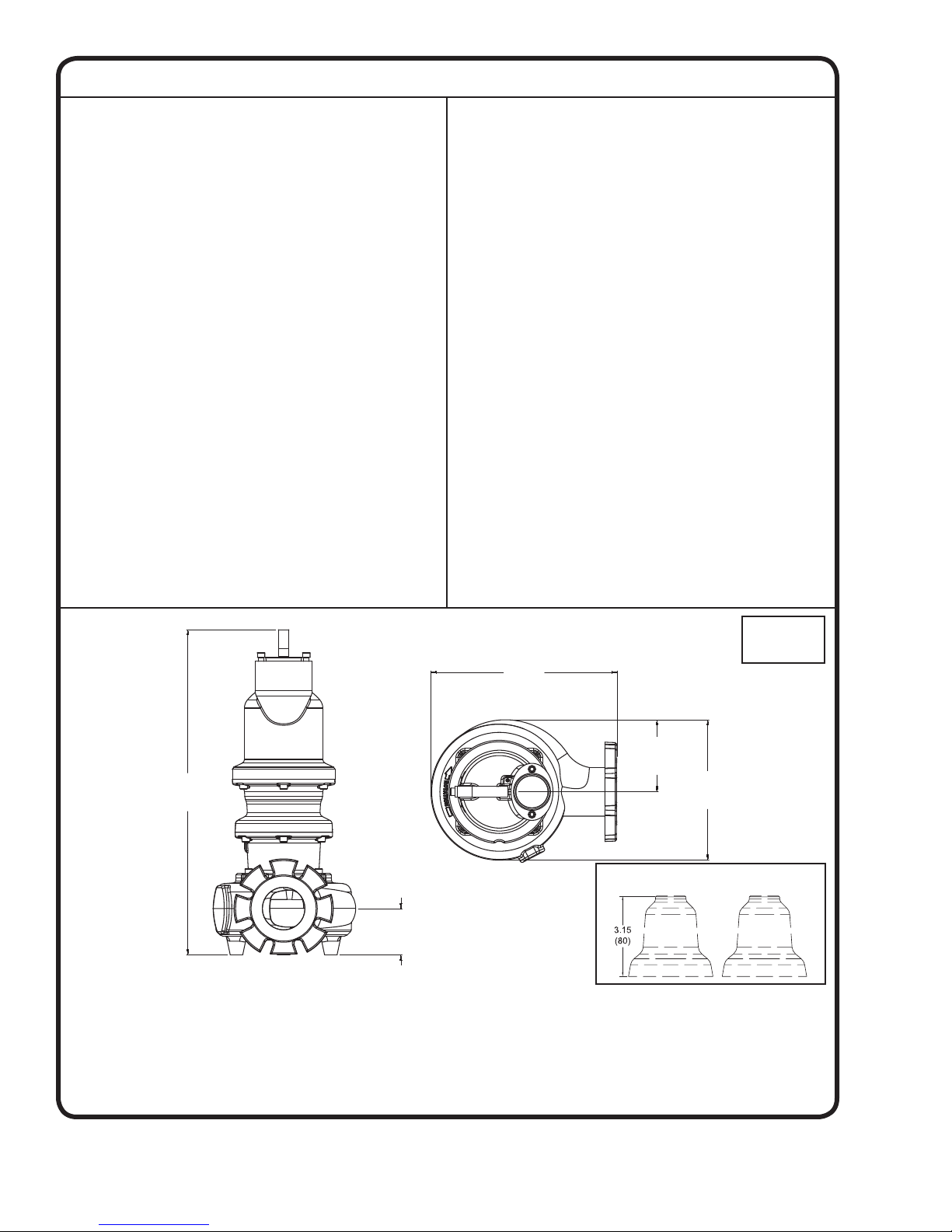
SECTION: A - PUMP SPECIFICATIONS: 3SHVRA (Vortex) Pump Models
DISCHARGE ......................3”, 125 lb. Horizontal Flange
Slotted to accomodate 80mm
ISO Flanges
LIQUID TEMPERATURE ... 104°F (40°C) Continuous
VOLUTE ............................. Cast Iron ASTM A-48, Class 30
WEAR RING ........................C954 Lead-Free Bronze
MOTOR HOUSING .............Cast Iron ASTM A-48, Class 30
SEAL PLATE ......................Cast Iron ASTM A-48, Class 30
IMPELLER:
Design ....................Vortex, With Pump Out
Vanes on Back Side. Dynamically
Balanced ISO G6.3
Material ................. Ductile Iron ASTM A-536, 65-45-12
SHAFT ...............................416 Stainless Steel
“O” RINGS .......................... Buna-N
HARDWARE .......................300 Series Stainless Steel
LIFTING BAIL .....................300 Series Stainless Steel
PAINT ...............................Epoxy Dupont Corlar® Amine
Epoxy, Two Coats
SEAL: Design ...................Tandem Mechanical, Oil Filled
Reservoir.
Material: Inboard....Rotating Face - Carbon
Stationary Face - Ceramic
Material: Outboard . Rotating Face - Silicon Carbide
Stationary Face - Silicon Carbide
Elastomer - Buna-N (Both Seals)
Hardware - 300 Series Stainless
(Both Seals)
CORD ENTRY ..................... Custom Molded, Quick Connected
for Sealing and Strain Relief
POWER CORD ...................CSA Certifi ed Submersible Power
Cable 2000V - Ordered Separately
SPEED ............................... 1750 RPM (Nominal)
UPPER BEARING:
Design ....................Single Row, Ball, Oil Lubricated
Load ...................... Radial
LOWER BEARING:
Design .....................Double Row, Ball, Oil Lubricated
Load ....................... Radial & Thrust
MOTOR: Design ................. NEMA B Three Phase Torque Curve.
Oil-Filled, Squirrel Cage Induction,
Inverter duty rated per NEMA
MG-1 part 31
Insulation ..............Class H, Varnish & Magnet Wire
SINGLE PHASE ................Dual Voltage 208-230V, 2, 3, 5HP.
Requires Overload Protection to be
included in control panel.
THREE PHASE .................Tri-voltage 208-230/460V & 575V,
2 thru 7.5HP. Requires Overload
Protection to be included in control
panel.
MOISTURE SENSOR .......Normally Open (N/O) with 330
K-Ohm Test Resistor Across
Probes. Requires Relay in
Control Panel
TEMPERATURE SENSOR ..Three Normally Closed (N/C).
To be wired in series with
contactor control circuit
OPTIONAL EQUIPMENT ..Seal Material, Impeller Trims,
Cord Length, Leg Kit (p/n 125506)
MARKINGS .......................CSA, CE
WEIGHT ............................215 Pounds (97.5 Kg)
NOISE EMISSION MAX ....In-Air 65 dB-A
SUBMERGENCE ..............Max Depth 66ft (20m)
Dimensions
inches (mm)
Optional Leg Kit - p/n 125506
IMPORTANT !
1.) MOISTURE AND TEMPERATURE SENSORS MUST BE CONNECTED TO VALIDATE THE CSA LISTING.
2.) A SPECIAL MOISTURE SENSOR RELAY IS REQUIRED IN THE CONTROL PANEL FOR PROPER OPERATION OF THE MOISTURE SENSORS.
CONTACT BARNES PUMPS FOR INFORMATION CONCERNING MOISTURE SENSING RELAYS FOR CUSTOMER SUPPLIED CONTROL PANELS.
3.) THESE PUMPS ARE CSA LISTED FOR PUMPING WATER AND WASTEWATER. DO NOT USE TO PUMP FLAMMABLE LIQUIDS.
4.) INSTALLATIONS SUCH AS DECORATIVE FOUNTAINS OR WATER FEATURES PROVIDED FOR VISUAL ENJOYMENT MUST BE INSTALLED IN
ACCORDANCE WITH THE NATIONAL ELECTRIC CODE ANSI/NFPA 70 AND/OR THE AUTHORITY HAVING JURISDICTION. THIS PUMP IS NOT
INTENDED FOR USE IN SWIMMING POOLS, RECREATIONAL WATER PARKS, OR INSTALLATIONS IN WHICH HUMAN CONTACT WITH PUMPED
MEDIA IS A COMMON OCCURRENCE.
5.) THIS PUMP IS NOT APPROPRIATE FOR THOSE APPLICATIONS SPECIFIED AS CLASS 1 DIVISION 1 HAZARDOUS LOCATIONS.
5
Page 6
SECTION: A - PUMP SPECIFICATIONS: 3SHMP (Enclosed Monovane) Pump Models
29.13
(740)
3.75
(95)
14.18
(360)
11.14
(283)
6.27
(159)
DISCHARGE ......................3”, 125 lb. Horizontal Flange
Slotted to accomodate 80mm
ISO Flanges
LIQUID TEMPERATURE ... 104°F (40°C) Continuous
VOLUTE ............................. Cast Iron ASTM A-48, Class 30
WEAR RING ........................C954 Lead-Free Bronze
MOTOR HOUSING .............Cast Iron ASTM A-48, Class 30
SEAL PLATE ......................Cast Iron ASTM A-48, Class 30
IMPELLER:
Design ....................Enclosed Monovane, With Pump
Out Vanes on Back Side.
Dynamically Balanced ISO G6.3
Material ................. Ductile Iron ASTM A-536, 65-45-12
SHAFT ...............................416 Stainless Steel
“O” RINGS .......................... Buna-N
HARDWARE .......................300 Series Stainless Steel
LIFTING BAIL .....................300 Series Stainless Steel
PAINT ...............................Epoxy Dupont Corlar® Amine
Epoxy, Two Coats
SEAL: Design ...................Tandem Mechanical, Oil Filled
Reservoir.
Material: Inboard....Rotating Face - Carbon
Stationary Face - Ceramic
Material: Outboard . Rotating Face - Silicon Carbide
Stationary Face - Silicon Carbide
Elastomer - Buna-N (Both Seals)
Hardware - 300 Series Stainless
(Both Seals)
CORD ENTRY ..................... Custom Molded, Quick Connected
for Sealing and Strain Relief
POWER CORD ...................CSA Certifi ed Submersible Power
Cable 2000V - Ordered Separately
SPEED ............................... 1750 RPM (Nominal)
UPPER BEARING:
Design ....................Single Row, Ball, Oil Lubricated
Load ...................... Radial
LOWER BEARING:
Design .....................Double Row, Ball, Oil Lubricated
Load ....................... Radial & Thrust
MOTOR: Design ................. NEMA B Three Phase Torque Curve.
Oil-Filled, Squirrel Cage Induction,
Inverter duty rated per NEMA
MG-1 part 31
Insulation ..............Class H, Varnish & Magnet Wire
SINGLE PHASE ................Dual voltage 208-230V 2 thru 5HP.
Requires Overload Protection to be
included in control panel.
THREE PHASE .................Tri-voltage 208-230/460V & 575V 2
thru 5HP. Requires Overload
Protection to be included in control
panel.
MOISTURE SENSOR .......Normally Open (N/O) with 330
K-Ohm Test Resistor Across
Probes. Requires Relay in
Control Panel
TEMPERATURE SENSOR ..Three Normally Closed (N/C).
To be wired in series with
contactor control circuit
OPTIONAL EQUIPMENT ..Seal Material, Impeller Trims,
Cord Length, Leg Kit (p/n 125506)
MARKINGS .......................CSA, CE
WEIGHT ............................209 Pounds (95 Kg)
NOISE EMISSION MAX ....In-Air 65 dB-A
SUBMERGENCE ..............Max Depth 66ft (20m)
Dimensions
inches (mm)
Optional Leg Kit - p/n 125506
IMPORTANT !
1.) MOISTURE AND TEMPERATURE SENSORS MUST BE CONNECTED TO VALIDATE THE CSA LISTING.
2.) A SPECIAL MOISTURE SENSOR RELAY IS REQUIRED IN THE CONTROL PANEL FOR PROPER OPERATION OF THE MOISTURE SENSORS.
CONTACT BARNES PUMPS FOR INFORMATION CONCERNING MOISTURE SENSING RELAYS FOR CUSTOMER SUPPLIED CONTROL PANELS.
3.) THESE PUMPS ARE CSA LISTED FOR PUMPING WATER AND WASTEWATER. DO NOT USE TO PUMP FLAMMABLE LIQUIDS.
4.) INSTALLATIONS SUCH AS DECORATIVE FOUNTAINS OR WATER FEATURES PROVIDED FOR VISUAL ENJOYMENT MUST BE INSTALLED IN
ACCORDANCE WITH THE NATIONAL ELECTRIC CODE ANSI/NFPA 70 AND/OR THE AUTHORITY HAVING JURISDICTION. THIS PUMP IS NOT
INTENDED FOR USE IN SWIMMING POOLS, RECREATIONAL WATER PARKS, OR INSTALLATIONS IN WHICH HUMAN CONTACT WITH PUMPED
MEDIA IS A COMMON OCCURRENCE.
5.) THIS PUMP IS NOT APPROPRIATE FOR THOSE APPLICATIONS SPECIFIED AS CLASS 1 DIVISION 1 HAZARDOUS LOCATIONS.
6
Page 7
SECTION: A - PUMP SPECIFICATIONS: 3SHMPA (Enclosed Monovane) Pump Models
DISCHARGE ......................3”, 125 lb. Horizontal Flange
Slotted to accomodate 80mm
ISO Flanges
LIQUID TEMPERATURE ... 104°F (40°C) Continuous
VOLUTE ............................. Cast Iron ASTM A-48, Class 30
WEAR RING ........................C954 Lead-Free Bronze
MOTOR HOUSING .............Cast Iron ASTM A-48, Class 30
SEAL PLATE ......................Cast Iron ASTM A-48, Class 30
IMPELLER:
Design ....................Enclosed Monovane, With Pump
Out Vanes on Back Side.
Dynamically Balanced ISO G6.3
Material ................. Ductile Iron ASTM A-536, 65-45-12
SHAFT ...............................416 Stainless Steel
“O” RINGS .......................... Buna-N
HARDWARE .......................300 Series Stainless Steel
LIFTING BAIL .....................300 Series Stainless Steel
PAINT ...............................Epoxy Dupont Corlar® Amine
Epoxy, Two Coats
SEAL: Design ...................Tandem Mechanical, Oil Filled
Reservoir.
Material: Inboard....Rotating Face - Carbon
Stationary Face - Ceramic
Material: Outboard . Rotating Face - Silicon Carbide
Stationary Face - Silicon Carbide
Elastomer - Buna-N (Both Seals)
Hardware - 300 Series Stainless
(Both Seals)
CORD ENTRY ..................... Custom Molded, Quick Connected
for Sealing and Strain Relief
POWER CORD ...................CSA Certifi ed Submersible Power
Cable 2000V - Ordered Separately
SPEED ............................... 1750 RPM (Nominal)
UPPER BEARING:
Design ....................Single Row, Ball, Oil Lubricated
Load ...................... Radial
LOWER BEARING:
Design .....................Double Row, Ball, Oil Lubricated
Load ....................... Radial & Thrust
MOTOR: Design ................. NEMA B Three Phase Torque Curve.
Oil-Filled, Squirrel Cage Induction,
Inverter duty rated per NEMA
MG-1 part 31
Insulation ..............Class H, Varnish & Magnet Wire
SINGLE PHASE ................Dual voltage 208-230V 3 thru 5HP.
Requires Overload Protection to be
included in control panel.
THREE PHASE .................Tri-voltage 208-230/460V & 575V
3 thru 7.5HP. Requires Overload
Protection to be included in control
panel.
MOISTURE SENSOR .......Normally Open (N/O) with 330
K-Ohm Test Resistor Across
Probes. Requires Relay in
Control Panel
TEMPERATURE SENSOR ..Three Normally Closed (N/C).
To be wired in series with
contactor control circuit
OPTIONAL EQUIPMENT ..Seal Material, Impeller Trims,
Cord Length, Leg Kit (p/n 125506)
MARKINGS .......................CSA, CE
WEIGHT ............................220 Pounds (100 Kg)
NOISE EMISSION MAX ....In-Air 65 dB-A
SUBMERGENCE ..............Max Depth 66ft (20m)
Dimensions
inches (mm)
Optional Leg Kit - p/n 125506
IMPORTANT !
1.) MOISTURE AND TEMPERATURE SENSORS MUST BE CONNECTED TO VALIDATE THE CSA LISTING.
2.) A SPECIAL MOISTURE SENSOR RELAY IS REQUIRED IN THE CONTROL PANEL FOR PROPER OPERATION OF THE MOISTURE SENSORS.
CONTACT BARNES PUMPS FOR INFORMATION CONCERNING MOISTURE SENSING RELAYS FOR CUSTOMER SUPPLIED CONTROL PANELS.
3.) THESE PUMPS ARE CSA LISTED FOR PUMPING WATER AND WASTEWATER. DO NOT USE TO PUMP FLAMMABLE LIQUIDS.
4.) INSTALLATIONS SUCH AS DECORATIVE FOUNTAINS OR WATER FEATURES PROVIDED FOR VISUAL ENJOYMENT MUST BE INSTALLED IN
ACCORDANCE WITH THE NATIONAL ELECTRIC CODE ANSI/NFPA 70 AND/OR THE AUTHORITY HAVING JURISDICTION. THIS PUMP IS NOT
INTENDED FOR USE IN SWIMMING POOLS, RECREATIONAL WATER PARKS, OR INSTALLATIONS IN WHICH HUMAN CONTACT WITH PUMPED
MEDIA IS A COMMON OCCURRENCE.
5.) THIS PUMP IS NOT APPROPRIATE FOR THOSE APPLICATIONS SPECIFIED AS CLASS 1 DIVISION 1 HAZARDOUS LOCATIONS.
7
Page 8
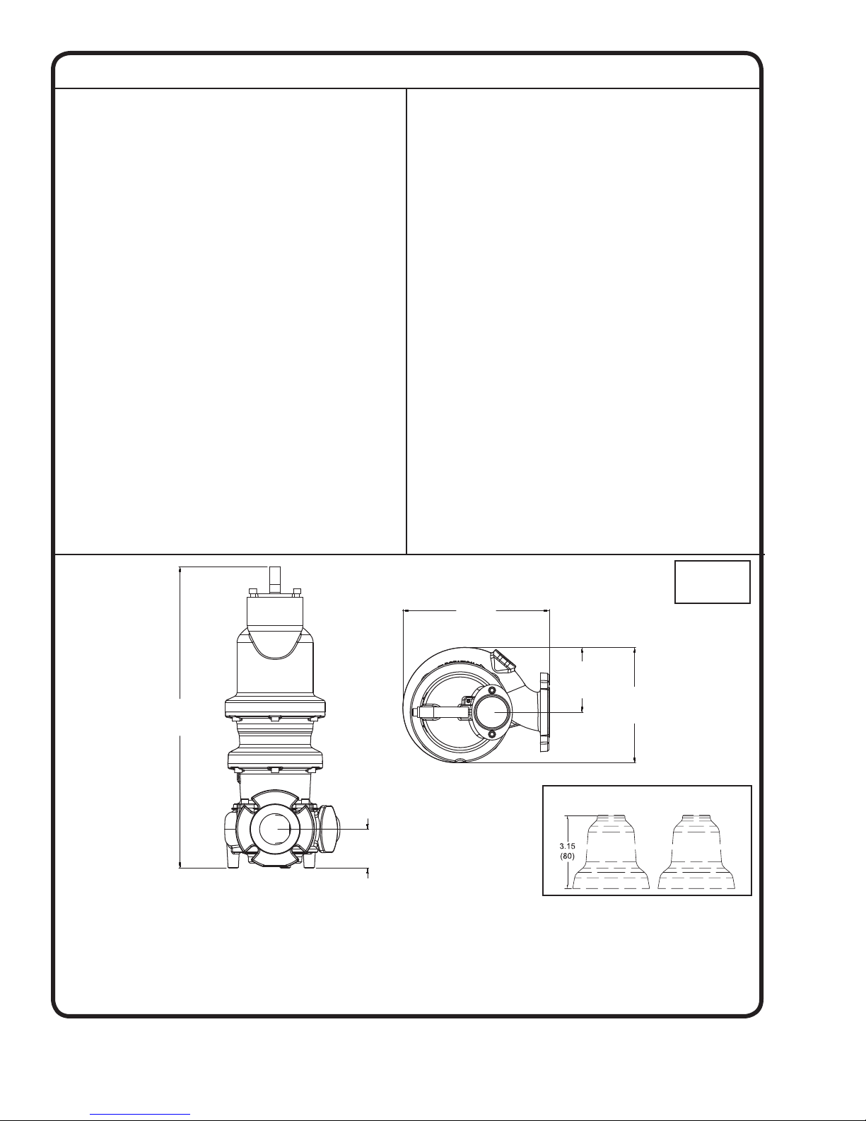
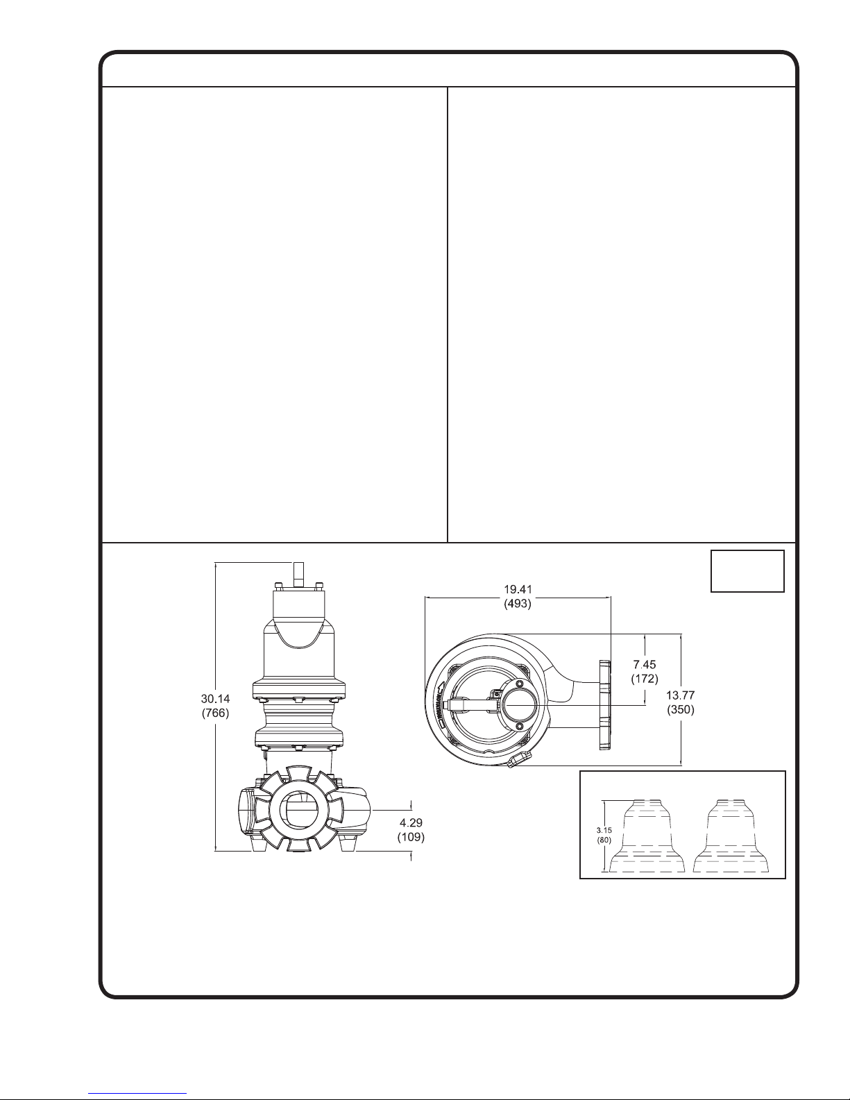
SECTION: A - PUMP SPECIFICATIONS: 4SHVA & 4SHVB (Vortex) Pump Models
30.53
(775)
4.33
(110)
17.48
(444)
6.76
(172)
13.19
(335)
DISCHARGE ......................4”, 125 lb. Horizontal Flange
Slotted to accomodate 100mm
ISO Flanges
LIQUID TEMPERATURE ... 104°F (40°C) Continuous
VOLUTE ............................. Cast Iron ASTM A-48, Class 30
WEAR RING ........................C954 Lead-Free Bronze
MOTOR HOUSING .............Cast Iron ASTM A-48, Class 30
SEAL PLATE ......................Cast Iron ASTM A-48, Class 30
IMPELLER:
Design ....................Vortex, With Pump Out
Vanes on Back Side. Dynamically
Balanced ISO G6.3
Material ................. Ductile Iron ASTM A-536, 65-45-12
SHAFT ...............................416 Stainless Steel
“O” RINGS .......................... Buna-N
HARDWARE .......................300 Series Stainless Steel
LIFTING BAIL .....................300 Series Stainless Steel
PAINT ...............................Epoxy Dupont Corlar® Amine
Epoxy, Two Coats
SEAL: Design ...................Tandem Mechanical, Oil Filled
Reservoir.
Material: Inboard....Rotating Face - Carbon
Stationary Face - Ceramic
Material: Outboard . Rotating Face - Silicon Carbide
Stationary Face - Silicon Carbide
Elastomer - Buna-N (Both Seals)
Hardware - 300 Series Stainless
(Both Seals)
CORD ENTRY ..................... Custom Molded, Quick Connected
for Sealing and Strain Relief
POWER CORD ...................CSA Certifi ed Submersible Power
Cable 2000V - Ordered Separately
SPEED ............................... 3450 RPM (Nominal)
UPPER BEARING:
Design ....................Single Row, Ball, Oil Lubricated
Load ...................... Radial
LOWER BEARING:
Design .....................Double Row, Ball, Oil Lubricated
Load ....................... Radial & Thrust
MOTOR: Design ................. NEMA B Three Phase Torque Curve.
Oil-Filled, Squirrel Cage Induction,
Inverter duty rated per NEMA
MG-1 part 31
Insulation ..............Class H, Varnish & Magnet Wire
THREE PHASE .................Tri-voltage 208-230/460 & 575V
7.5 thru 10HP. Requires Overload
Protection to be included in control
panel.
MOISTURE SENSOR .......Normally Open (N/O) with 330
K-Ohm Test Resistor Across
Probes. Requires Relay in
Control Panel
TEMPERATURE SENSOR ..Three Normally Closed (N/C).
To be wired in series with
contactor control circuit
OPTIONAL EQUIPMENT ..Seal Material, Impeller Trims,
Cord Length, Leg Kit (p/n 125506)
MARKINGS .......................CSA, CE
WEIGHT ............................218 Pounds (99 Kg)
NOISE EMISSION MAX ....In-Air 65 dB-A
SUBMERGENCE ..............Max Depth 66ft (20m)
Dimensions
inches (mm)
Optional Leg Kit - p/n 125506
IMPORTANT !
1.) MOISTURE AND TEMPERATURE SENSORS MUST BE CONNECTED TO VALIDATE THE CSA LISTING.
2.) A SPECIAL MOISTURE SENSOR RELAY IS REQUIRED IN THE CONTROL PANEL FOR PROPER OPERATION OF THE MOISTURE SENSORS.
CONTACT BARNES PUMPS FOR INFORMATION CONCERNING MOISTURE SENSING RELAYS FOR CUSTOMER SUPPLIED CONTROL PANELS.
3.) THESE PUMPS ARE CSA LISTED FOR PUMPING WATER AND WASTEWATER. DO NOT USE TO PUMP FLAMMABLE LIQUIDS.
4.) INSTALLATIONS SUCH AS DECORATIVE FOUNTAINS OR WATER FEATURES PROVIDED FOR VISUAL ENJOYMENT MUST BE INSTALLED IN
ACCORDANCE WITH THE NATIONAL ELECTRIC CODE ANSI/NFPA 70 AND/OR THE AUTHORITY HAVING JURISDICTION. THIS PUMP IS NOT
INTENDED FOR USE IN SWIMMING POOLS, RECREATIONAL WATER PARKS, OR INSTALLATIONS IN WHICH HUMAN CONTACT WITH PUMPED
MEDIA IS A COMMON OCCURRENCE.
5.) THIS PUMP IS NOT APPROPRIATE FOR THOSE APPLICATIONS SPECIFIED AS CLASS 1 DIVISION 1 HAZARDOUS LOCATIONS.
8
Page 9
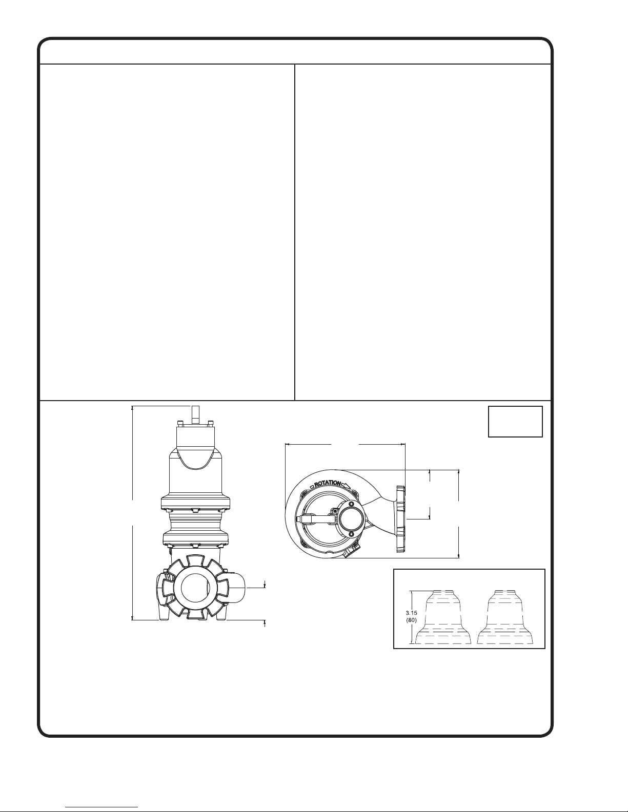
SECTION: A - PUMP SPECIFICATIONS: 4SHVBA (Vortex) Pump Models
DISCHARGE ......................4”, 125 lb. Horizontal Flange
Slotted to accomodate 100mm
ISO Flanges
LIQUID TEMPERATURE ... 104°F (40°C) Continuous
VOLUTE ............................. Cast Iron ASTM A-48, Class 30
WEAR RING ........................C954 Lead-Free Bronze
MOTOR HOUSING .............Cast Iron ASTM A-48, Class 30
SEAL PLATE ......................Cast Iron ASTM A-48, Class 30
IMPELLER:
Design ....................Vortex, With Pump Out
Vanes on Back Side. Dynamically
Balanced ISO G6.3
Material ................. Ductile Iron ASTM A-536, 65-45-12
SHAFT ...............................416 Stainless Steel
“O” RINGS .......................... Buna-N
HARDWARE .......................300 Series Stainless Steel
LIFTING BAIL .....................300 Series Stainless Steel
PAINT ...............................Epoxy Dupont Corlar® Amine
Epoxy, Two Coats
SEAL: Design ...................Tandem Mechanical, Oil Filled
Reservoir.
Material: Inboard....Rotating Face - Carbon
Stationary Face - Ceramic
Material: Outboard . Rotating Face - Silicon Carbide
Stationary Face - Silicon Carbide
Elastomer - Buna-N (Both Seals)
Hardware - 300 Series Stainless
(Both Seals)
CORD ENTRY ..................... Custom Molded, Quick Connected
for Sealing and Strain Relief
POWER CORD ...................CSA Certifi ed Submersible Power
Cable 2000V - Ordered Separately
SPEED ............................... 1750 RPM (Nominal)
UPPER BEARING:
Design ....................Single Row, Ball, Oil Lubricated
Load ...................... Radial
LOWER BEARING:
Design .....................Double Row, Ball, Oil Lubricated
Load ....................... Radial & Thrust
MOTOR: Design ................. NEMA B Three Phase Torque Curve.
Oil-Filled, Squirrel Cage Induction,
Inverter duty rated per NEMA
MG-1 part 31
Insulation ..............Class H, Varnish & Magnet Wire
THREE PHASE .................Tri-voltage 208-230/460 2 thru
10HP, 575V 2 thru 10HP. Requires
Overload Protection to be included
in control panel.
MOISTURE SENSOR .......Normally Open (N/O) with 330
K-Ohm Test Resistor Across
Probes. Requires Relay in
Control Panel
TEMPERATURE SENSOR ..Three Normally Closed (N/C).
To be wired in series with
contactor control circuit
OPTIONAL EQUIPMENT ..Seal Material, Impeller Trims,
Cord Length, Leg Kit (p/n 125506)
MARKINGS .......................CSA, CE
WEIGHT ............................218 Pounds (99 Kg)
NOISE EMISSION MAX ....In-Air 65 dB-A
SUBMERGENCE ..............Max Depth 66ft (20m)
Dimensions
inches (mm)
Optional Leg Kit - p/n 125506
IMPORTANT !
1.) MOISTURE AND TEMPERATURE SENSORS MUST BE CONNECTED TO VALIDATE THE CSA LISTING.
2.) A SPECIAL MOISTURE SENSOR RELAY IS REQUIRED IN THE CONTROL PANEL FOR PROPER OPERATION OF THE MOISTURE SENSORS.
CONTACT BARNES PUMPS FOR INFORMATION CONCERNING MOISTURE SENSING RELAYS FOR CUSTOMER SUPPLIED CONTROL PANELS.
3.) THESE PUMPS ARE CSA LISTED FOR PUMPING WATER AND WASTEWATER. DO NOT USE TO PUMP FLAMMABLE LIQUIDS.
4.) INSTALLATIONS SUCH AS DECORATIVE FOUNTAINS OR WATER FEATURES PROVIDED FOR VISUAL ENJOYMENT MUST BE INSTALLED IN
ACCORDANCE WITH THE NATIONAL ELECTRIC CODE ANSI/NFPA 70 AND/OR THE AUTHORITY HAVING JURISDICTION. THIS PUMP IS NOT
INTENDED FOR USE IN SWIMMING POOLS, RECREATIONAL WATER PARKS, OR INSTALLATIONS IN WHICH HUMAN CONTACT WITH PUMPED
MEDIA IS A COMMON OCCURRENCE.
5.) THIS PUMP IS NOT APPROPRIATE FOR THOSE APPLICATIONS SPECIFIED AS CLASS 1 DIVISION 1 HAZARDOUS LOCATIONS.
9
Page 10
SECTION: A - PUMP SPECIFICATIONS: 4SHMS (Enclosed Monovane) Pump Models
30.10
(765)
4.50
(114)
16.83
(427)
12.45
(316)
6.95
(177)
DISCHARGE ......................4”, 125 lb. Horizontal Flange
Slotted to accomodate 100mm
ISO Flanges
LIQUID TEMPERATURE ... 104°F (40°C) Continuous
VOLUTE ............................. Cast Iron ASTM A-48, Class 30
WEAR RING ........................C954 Lead-Free Bronze
MOTOR HOUSING .............Cast Iron ASTM A-48, Class 30
SEAL PLATE ......................Cast Iron ASTM A-48, Class 30
IMPELLER:
Design ....................Enclosed Monovane, With Pump
Out Vanes on Back Side.
Dynamically Balanced ISO G6.3
Material ................. Ductile Iron ASTM A-536, 65-45-12
SHAFT ...............................416 Stainless Steel
“O” RINGS .......................... Buna-N
HARDWARE .......................300 Series Stainless Steel
LIFTING BAIL .....................300 Series Stainless Steel
PAINT ...............................Epoxy Dupont Corlar® Amine
Epoxy, Two Coats
SEAL: Design ...................Tandem Mechanical, Oil Filled
Reservoir.
Material: Inboard....Rotating Face - Carbon
Stationary Face - Ceramic
Material: Outboard . Rotating Face - Silicon Carbide
Stationary Face - Silicon Carbide
Elastomer - Buna-N (Both Seals)
Hardware - 300 Series Stainless
(Both Seals)
CORD ENTRY ..................... Custom Molded, Quick Connected
for Sealing and Strain Relief
POWER CORD ...................CSA Certifi ed Submersible Power
Cable 2000V - Ordered Separately
SPEED ............................... 1750 RPM (Nominal)
UPPER BEARING:
Design ....................Single Row, Ball, Oil Lubricated
Load ...................... Radial
LOWER BEARING:
Design .....................Double Row, Ball, Oil Lubricated
Load ....................... Radial & Thrust
MOTOR: Design ................. NEMA B Three Phase Torque Curve.
Oil-Filled, Squirrel Cage Induction,
Inverter duty rated per NEMA
MG-1 part 31
Insulation ..............Class H, Varnish & Magnet Wire
SINGLE PHASE ................Dual voltage 208-230 3 thru 5HP,
Requires Overload Protection to be
included in control panel.
THREE PHASE .................Tri-voltage 208-230/460V, 575V
3 thru 7.5HP. Requires Overload
Protection to be included in control
panel.
MOISTURE SENSOR .......Normally Open (N/O) with 330
K-Ohm Test Resistor Across
Probes. Requires Relay in
Control Panel
TEMPERATURE SENSOR ..Three Normally Closed (N/C).
To be wired in series with
contactor control circuit
OPTIONAL EQUIPMENT ..Seal Material, Impeller Trims,
Cord Length, Leg Kit (p/n 125506)
MARKINGS .......................CSA, CE
WEIGHT ............................231 Pounds (105 Kg)
NOISE EMISSION MAX ....In-Air 65 dB-A
SUBMERGENCE ..............Max Depth 66ft (20m)
Dimensions
inches (mm)
Optional Leg Kit - p/n 125506
IMPORTANT !
1.) MOISTURE AND TEMPERATURE SENSORS MUST BE CONNECTED TO VALIDATE THE CSA LISTING.
2.) A SPECIAL MOISTURE SENSOR RELAY IS REQUIRED IN THE CONTROL PANEL FOR PROPER OPERATION OF THE MOISTURE SENSORS.
CONTACT BARNES PUMPS FOR INFORMATION CONCERNING MOISTURE SENSING RELAYS FOR CUSTOMER SUPPLIED CONTROL PANELS.
3.) THESE PUMPS ARE CSA LISTED FOR PUMPING WATER AND WASTEWATER. DO NOT USE TO PUMP FLAMMABLE LIQUIDS.
4.) INSTALLATIONS SUCH AS DECORATIVE FOUNTAINS OR WATER FEATURES PROVIDED FOR VISUAL ENJOYMENT MUST BE INSTALLED IN
ACCORDANCE WITH THE NATIONAL ELECTRIC CODE ANSI/NFPA 70 AND/OR THE AUTHORITY HAVING JURISDICTION. THIS PUMP IS NOT
INTENDED FOR USE IN SWIMMING POOLS, RECREATIONAL WATER PARKS, OR INSTALLATIONS IN WHICH HUMAN CONTACT WITH PUMPED
MEDIA IS A COMMON OCCURRENCE.
5.) THIS PUMP IS NOT APPROPRIATE FOR THOSE APPLICATIONS SPECIFIED AS CLASS 1 DIVISION 1 HAZARDOUS LOCATIONS.
10
Page 11

SECTION: A - PUMP SPECIFICATIONS: 4SHMC (Enclosed Monovane) Pump Models
30.08
(764)
4.40
(112)
18.78
(477)
13.85
(352)
7.68
(195)
DISCHARGE ......................4”, 125 lb. Horizontal Flange
Slotted to accomodate 100mm
ISO Flanges
LIQUID TEMPERATURE ... 104°F (40°C) Continuous
VOLUTE ............................. Cast Iron ASTM A-48, Class 30
WEAR RING ........................C954 Lead-Free Bronze
MOTOR HOUSING .............Cast Iron ASTM A-48, Class 30
SEAL PLATE ......................Cast Iron ASTM A-48, Class 30
IMPELLER:
Design ....................Enclosed Monovane, With Pump
Out Vanes on Back Side.
Dynamically Balanced ISO G6.3
Material ................. Ductile Iron ASTM A-536, 65-45-12
SHAFT ...............................416 Stainless Steel
“O” RINGS .......................... Buna-N
HARDWARE .......................300 Series Stainless Steel
LIFTING BAIL .....................300 Series Stainless Steel
PAINT ...............................Epoxy Dupont Corlar® Amine
Epoxy, Two Coats
SEAL: Design ...................Tandem Mechanical, Oil Filled
Reservoir.
Material: Inboard....Rotating Face - Carbon
Stationary Face - Ceramic
Material: Outboard . Rotating Face - Silicon Carbide
Stationary Face - Silicon Carbide
Elastomer - Buna-N (Both Seals)
Hardware - 300 Series Stainless
(Both Seals)
CORD ENTRY ..................... Custom Molded, Quick Connected
for Sealing and Strain Relief
POWER CORD ...................CSA Certifi ed Submersible Power
Cable 2000V - Ordered Separately
SPEED ............................... 1750 RPM (Nominal)
UPPER BEARING:
Design ....................Single Row, Ball, Oil Lubricated
Load ...................... Radial
LOWER BEARING:
Design .....................Double Row, Ball, Oil Lubricated
Load ....................... Radial & Thrust
MOTOR: Design ................. NEMA B Three Phase Torque Curve.
Oil-Filled, Squirrel Cage Induction,
Inverter duty rated per NEMA
MG-1 part 31
Insulation ..............Class H, Varnish & Magnet Wire
SINGLE PHASE ................Dual voltage 208-230 5HP.
Requires Overload Protection to be
included in control panel.
THREE PHASE .................Tri-voltage 208-230/460V, 575V
5 thru 10HP. Requires Overload
Protection to be included in control
panel.
MOISTURE SENSOR .......Normally Open (N/O) with 330
K-Ohm Test Resistor Across
Probes. Requires Relay in
Control Panel
TEMPERATURE SENSOR ..Three Normally Closed (N/C).
To be wired in series with
contactor control circuit
OPTIONAL EQUIPMENT ..Seal Material, Impeller Trims,
Cord Length, Leg Kit (p/n 125506)
MARKINGS .......................CSA, CE
WEIGHT ............................231 Pounds (105 Kg)
NOISE EMISSION MAX ....In-Air 65 dB-A
SUBMERGENCE ..............Max Depth 66ft (20m)
Dimensions
inches (mm)
Optional Leg Kit - p/n 125506
IMPORTANT !
1.) MOISTURE AND TEMPERATURE SENSORS MUST BE CONNECTED TO VALIDATE THE CSA LISTING.
2.) A SPECIAL MOISTURE SENSOR RELAY IS REQUIRED IN THE CONTROL PANEL FOR PROPER OPERATION OF THE MOISTURE SENSORS.
CONTACT BARNES PUMPS FOR INFORMATION CONCERNING MOISTURE SENSING RELAYS FOR CUSTOMER SUPPLIED CONTROL PANELS.
3.) THESE PUMPS ARE CSA LISTED FOR PUMPING WATER AND WASTEWATER. DO NOT USE TO PUMP FLAMMABLE LIQUIDS.
4.) INSTALLATIONS SUCH AS DECORATIVE FOUNTAINS OR WATER FEATURES PROVIDED FOR VISUAL ENJOYMENT MUST BE INSTALLED IN
ACCORDANCE WITH THE NATIONAL ELECTRIC CODE ANSI/NFPA 70 AND/OR THE AUTHORITY HAVING JURISDICTION. THIS PUMP IS NOT
INTENDED FOR USE IN SWIMMING POOLS, RECREATIONAL WATER PARKS, OR INSTALLATIONS IN WHICH HUMAN CONTACT WITH PUMPED
MEDIA IS A COMMON OCCURRENCE.
5.) THIS PUMP IS NOT APPROPRIATE FOR THOSE APPLICATIONS SPECIFIED AS CLASS 1 DIVISION 1 HAZARDOUS LOCATIONS.
11
Page 12

SECTION: A - PUMP SPECIFICATIONS: 4SHDF (Enclosed Dual Vane) Pump Models
30.10
(765)
4.50
(114)
16.83
(427)
12.45
(316)
6.95
(177)
DISCHARGE ......................4”, 125 lb. Horizontal Flange
Slotted to accomodate 100mm
ISO Flanges
LIQUID TEMPERATURE ... 104°F (40°C) Continuous
VOLUTE ............................. Cast Iron ASTM A-48, Class 30
WEAR RING ........................C954 Lead-Free Bronze
MOTOR HOUSING .............Cast Iron ASTM A-48, Class 30
SEAL PLATE ......................Cast Iron ASTM A-48, Class 30
IMPELLER:
Design ....................Enclosed Dual Vane, With Pump
Out Vanes on Back Side.
Dynamically Balanced ISO G6.3
Material ................. Ductile Iron ASTM A-536, 65-45-12
SHAFT ...............................416 Stainless Steel
“O” RINGS .......................... Buna-N
HARDWARE .......................300 Series Stainless Steel
LIFTING BAIL .....................300 Series Stainless Steel
PAINT ...............................Epoxy Dupont Corlar® Amine
Epoxy, Two Coats
SEAL: Design ...................Tandem Mechanical, Oil Filled
Reservoir.
Material: Inboard....Rotating Face - Carbon
Stationary Face - Ceramic
Material: Outboard . Rotating Face - Silicon Carbide
Stationary Face - Silicon Carbide
Elastomer - Buna-N (Both Seals)
Hardware - 300 Series Stainless
(Both Seals)
CORD ENTRY ..................... Custom Molded, Quick Connected
for Sealing and Strain Relief
POWER CORD ...................CSA Certifi ed Submersible Power
Cable 2000V - Ordered Separately
SPEED ............................... 1750 RPM (Nominal)
UPPER BEARING:
Design ....................Single Row, Ball, Oil Lubricated
Load ...................... Radial
LOWER BEARING:
Design .....................Double Row, Ball, Oil Lubricated
Load ....................... Radial & Thrust
MOTOR: Design ................. NEMA B Three Phase Torque Curve.
Oil-Filled, Squirrel Cage Induction,
Inverter duty rated per NEMA
MG-1 part 31
Insulation ..............Class H, Varnish & Magnet Wire
SINGLE PHASE ................Dual voltage 208-230 3 thru 5HP.
Requires Overload Protection to be
included in control panel.
THREE PHASE .................Tri-voltage 208-230/460V &
575V 3 thru 10HP. Requires
Overload Protection to be
included in control panel.
MOISTURE SENSOR .......Normally Open (N/O) with 330
K-Ohm Test Resistor Across
Probes. Requires Relay in
Control Panel
TEMPERATURE SENSOR ..Three Normally Closed (N/C).
To be wired in series with
contactor control circuit
OPTIONAL EQUIPMENT ..Seal Material, Impeller Trims,
Cord Length, Leg Kit (p/n 125506)
MARKINGS .......................CSA, CE
WEIGHT ............................228 Pounds (104 Kg)
NOISE EMISSION MAX ....In-Air 65 dB-A
SUBMERGENCE ..............Max Depth 66ft (20m)
Dimensions
inches (mm)
Optional Leg Kit - p/n 125506
IMPORTANT !
1.) MOISTURE AND TEMPERATURE SENSORS MUST BE CONNECTED TO VALIDATE THE CSA LISTING.
2.) A SPECIAL MOISTURE SENSOR RELAY IS REQUIRED IN THE CONTROL PANEL FOR PROPER OPERATION OF THE MOISTURE SENSORS.
CONTACT BARNES PUMPS FOR INFORMATION CONCERNING MOISTURE SENSING RELAYS FOR CUSTOMER SUPPLIED CONTROL PANELS.
3.) THESE PUMPS ARE CSA LISTED FOR PUMPING WATER AND WASTEWATER. DO NOT USE TO PUMP FLAMMABLE LIQUIDS.
4.) INSTALLATIONS SUCH AS DECORATIVE FOUNTAINS OR WATER FEATURES PROVIDED FOR VISUAL ENJOYMENT MUST BE INSTALLED IN
ACCORDANCE WITH THE NATIONAL ELECTRIC CODE ANSI/NFPA 70 AND/OR THE AUTHORITY HAVING JURISDICTION. THIS PUMP IS NOT
INTENDED FOR USE IN SWIMMING POOLS, RECREATIONAL WATER PARKS, OR INSTALLATIONS IN WHICH HUMAN CONTACT WITH PUMPED
MEDIA IS A COMMON OCCURRENCE.
5.) THIS PUMP IS NOT APPROPRIATE FOR THOSE APPLICATIONS SPECIFIED AS CLASS 1 DIVISION 1 HAZARDOUS LOCATIONS.
12
Page 13
SECTION: A - PUMP SPECIFICATIONS: 4SHDG (Enclosed Dual Vane) Pump Models
30.08
(764)
4.40
(112)
18.78
(477)
13.85
(352)
7.68
(195)
DISCHARGE ......................4”, 125 lb. Horizontal Flange
Slotted to accomodate 100mm
ISO Flanges
LIQUID TEMPERATURE ... 104°F (40°C) Continuous
VOLUTE ............................. Cast Iron ASTM A-48, Class 30
WEAR RING ........................C954 Lead-Free Bronze
MOTOR HOUSING .............Cast Iron ASTM A-48, Class 30
SEAL PLATE ......................Cast Iron ASTM A-48, Class 30
IMPELLER:
Design ....................Enclosed Dual Vane, With Pump
Out Vanes on Back Side.
Dynamically Balanced ISO G6.3
Material ................. Ductile Iron ASTM A-536, 65-45-12
SHAFT ...............................416 Stainless Steel
“O” RINGS .......................... Buna-N
HARDWARE .......................300 Series Stainless Steel
LIFTING BAIL .....................300 Series Stainless Steel
PAINT ...............................Epoxy Dupont Corlar® Amine
Epoxy, Two Coats
SEAL: Design ...................Tandem Mechanical, Oil Filled
Reservoir.
Material: Inboard....Rotating Face - Carbon
Stationary Face - Ceramic
Material: Outboard . Rotating Face - Silicon Carbide
Stationary Face - Silicon Carbide
Elastomer - Buna-N (Both Seals)
Hardware - 300 Series Stainless
(Both Seals)
CORD ENTRY ..................... Custom Molded, Quick Connected
for Sealing and Strain Relief
POWER CORD ...................CSA Certifi ed Submersible Power
Cable 2000V - Ordered Separately
SPEED ............................... 1750 RPM (Nominal)
UPPER BEARING:
Design ....................Single Row, Ball, Oil Lubricated
Load ...................... Radial
LOWER BEARING:
Design .....................Double Row, Ball, Oil Lubricated
Load ....................... Radial & Thrust
MOTOR: Design ................. NEMA B Three Phase Torque Curve.
Oil-Filled, Squirrel Cage Induction,
Inverter duty rated per NEMA
MG-1 part 31
Insulation ..............Class H, Varnish & Magnet Wire
SINGLE PHASE ................Dual voltage 208-230 5HP.
Requires Overload Protection to be
included in control panel.
THREE PHASE .................Tri-voltage 208-230/460V
& 575V 5 thru 10HP. Requires
Overload Protection to be
included in control panel.
MOISTURE SENSOR .......Normally Open (N/O) with 330
K-Ohm Test Resistor Across
Probes. Requires Relay in
Control Panel
TEMPERATURE SENSOR ..Three Normally Closed (N/C).
To be wired in series with
contactor control circuit
OPTIONAL EQUIPMENT ..Seal Material, Impeller Trims,
Cord Length, Leg Kit (p/n 125506)
MARKINGS .......................CSA, CE
WEIGHT ............................228 Pounds (104 Kg)
NOISE EMISSION MAX ....In-Air 65 dB-A
SUBMERGENCE ..............Max Depth 66ft (20m)
Dimensions
inches (mm)
Optional Leg Kit - p/n 125506
IMPORTANT !
1.) MOISTURE AND TEMPERATURE SENSORS MUST BE CONNECTED TO VALIDATE THE CSA LISTING.
2.) A SPECIAL MOISTURE SENSOR RELAY IS REQUIRED IN THE CONTROL PANEL FOR PROPER OPERATION OF THE MOISTURE SENSORS.
CONTACT BARNES PUMPS FOR INFORMATION CONCERNING MOISTURE SENSING RELAYS FOR CUSTOMER SUPPLIED CONTROL PANELS.
3.) THESE PUMPS ARE CSA LISTED FOR PUMPING WATER AND WASTEWATER. DO NOT USE TO PUMP FLAMMABLE LIQUIDS.
4.) INSTALLATIONS SUCH AS DECORATIVE FOUNTAINS OR WATER FEATURES PROVIDED FOR VISUAL ENJOYMENT MUST BE INSTALLED IN
ACCORDANCE WITH THE NATIONAL ELECTRIC CODE ANSI/NFPA 70 AND/OR THE AUTHORITY HAVING JURISDICTION. THIS PUMP IS NOT
INTENDED FOR USE IN SWIMMING POOLS, RECREATIONAL WATER PARKS, OR INSTALLATIONS IN WHICH HUMAN CONTACT WITH PUMPED
MEDIA IS A COMMON OCCURRENCE.
5.) THIS PUMP IS NOT APPROPRIATE FOR THOSE APPLICATIONS SPECIFIED AS CLASS 1 DIVISION 1 HAZARDOUS LOCATIONS.
13
Page 14
SECTION B: GENERAL INFORMATION
and the suction will become plugged.
B-1) To the Purchaser:
Congratulations! You are the owner of one of the fi nest pumps
on the market today. CP&S pumps are products engineered
and manufactured of high quality components. Over one
hundred years of pump building experience along with a
continuing quality assurance program combine to produce a
pump which will stand up to the toughest applications. This
manual will provide helpful information concerning installation,
maintenance, and proper service guidelines.
B-2) Receiving:
Upon receiving the pump, it should be inspected for
damage or shortages. If damage has occurred, fi le a
claim immediately with the company that delivered the
pump. MAKE CERTAIN TO RETAIN THIS MANUAL!
B-3) Storage:
Short Term- CP&S Pumps are manufactured for effi cient
performance following short inoperative periods in storage.
For best results, pumps can be retained in storage, as factory
assembled, in a dry atmosphere with constant temperatures
for up to six (6) months.
Long Term - Any length of time exceeding six (6) months,
but not more than twenty-four (24) months. The unit should
be stored in a temperature controlled area, a roofed over
walled enclosure that provides protection from the elements
(rain, snow, wind-blown dust, etc.), and whose temperature
can be maintained between +40 deg. F and +120 deg. F.
(4.4 - 49°C). Pump should be stored in its original shipping
container. On initial start up, rotate impeller by hand to
assure seal and impeller rotate freely. If it is required that
the pump be installed and tested before the long term
storage begins, such installation will be allowed provided:
1.) The pump is not installed under water for more than
one (1) month.
2.) Immediately upon satisfactory completion of the test,
the pump is removed, thoroughly dried, repacked in the
original shipping container, and placed in a temperature
controlled storage area.
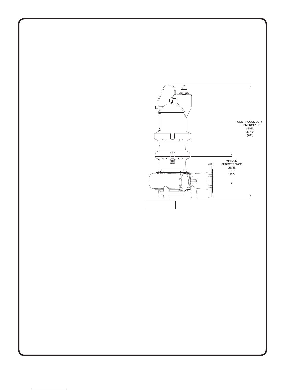
C-1.1) Submergence:
It is recommended that the pump be operated in the
Continuous Duty Submergence condition and the sump
liquid level should never be less than the Minimum
Submergence Level (See Fig. 1). The time required to
draw the well down from top of motor to the minimum
submergence level should not be greater than 15 minutes.
NOTE: Outer shaft seal must be in liquid when motor is
operated, whether motor is submerged or in air.
FIGURE 1
C-2) Discharge:
Discharge piping should be as short as possible. Both a
check valve and a shut-off valve are recommended for
each pump being used. The check valve is used to prevent
backfl ow into the sump. Excessive backfl ow can cause
fl ooding and/or damage to the pump. The shut-off valve
is used to stop system fl ow during pump or check valve
servicing.
B-4) Service Centers:
For the location of the nearest Barnes Service Center, check
your Barnes representative or Crane Pumps & Systems,
Inc., Service Department in Piqua, Ohio, telephone (937)
778-8947 or Crane Pumps & Systems Canada, in Brampton,
Ontario, (905) 457-6223.
SECTION C: INSTALLATION
C-1) Location:
These self-contained pumping units are recommended for
use in a sump, lift station or basin.
for submerged continuous duty (15 minutes duty in air
at nameplate horsepower), pumping sewage, effl uent,
wastewater or other nonexplosive or noncorrosive liquids
not above 104°F (40°C). Never install the pump in a trench,
ditch or hole with a dirt bottom; the legs will sink into the dirt
This pump is designed
Barnes Pumps manufactures a break away fi tting discharge
system designed to allow the submersible wastewater pump
to be installed or removed without requiring personnel to
enter the wet well. Place the Break Away Fitting (BAF) in
position. Temporarily secure the guide rails in the upper
mounting brackets and locate the base elbow on the bottom
of the wet well. Level the base elbow with grout and/or
shims. Install the intermediate support brackets, if required.
Make sure the rails are in a true vertical position so the
pump will clear the access opening and will slide freely
down the rails into place on the discharge base elbow. Once
the rails are in proper alignment, bolt the base elbow into
the fl oor of the station and connect the discharge pipe to
the elbow. Connect the movable portion and other supplied
fi ttings of the BAF onto the pump and lower into wet well.
See the Break Away Fitting manual for more information.
14
Page 15
C-3) Liquid Level Controls:
It is recommended to use a liquid level control system
that allows the on and off point to be separated by at least
twelve inches. An additional set point (lag point) should
be incorporated with an alternator switching system for
a duplex (two pump) station. A high level alarm may be
required to alert maintenance personnel that there is a
high water situation in the wet well should the output of the
pump station drop below the infl ow rate. A low level cut off
may be installed to provide system shutdown if the main
level control system malfunctions. The off point should be
positioned so that the liquid level never drops below the
minimum continuous duty point for the pump shown in
fi gure 1.
C-4.1) Electrical Connections:
WARNING! - All model pumps and
control panels must be properly
grounded per the NATIONAL
ELECTRIC CODE or CANADIAN
ELECTRIC CODE, State, Province
and local codes. Improper
grounding voids warranty.
C-4) Power/Control Cord:
The power/control cord used with pump has a patent
pending “quick disconnect” feature that allows the cord
to be easily attached and disconnected at the pump. The
maximum amperage rating for the cord is cast in the top of
the cast stainless mounting plate. The voltage connection
for the motor is determined by the cord assembly used.
Low voltage cords (208 & 230 Volt) utilize a molded quick
connect plug that is colored black. High voltage cords
(460 & 575 Volt) utilize a molded quick connect cord
that is colored orange. It is important to verify that the
cord being used is rated for the nameplate voltage
and amperage rating shown on the pump nameplate.
Refer to Chart on page 7. No internal wiring adjustments
are necessary for dual and tri-voltage pumps. All jumper
connections to set the proper voltage are made by the cord
plug itself.
The cord assembly mounted to the pump must not be
modifi ed in any way except for shortening to a specifi c
application. Any splice between the pump and the control
panel must be made in accordance with all applicable
electric codes. It is recommended that a junction box (if
used) be mounted outside the sump or be of at least Nema
6 or 6P construction with NEMA 6 or 6P watertight cord
grips if located within the wet well. A water and vapor tight
seal fi tting MUST be used in conduit leaving the wet well
to prevent moisture and gasses from reaching the control
panel. Prior to installation, the pump power cable should be
inspected for nicks or damage. If damaged, the cord should
be replaced before installation.
DO NOT USE THE POWER CORD TO LIFT PUMP.
C-4.1) Electrical Connections:
When the electrical connections are made, the lead wires
from the power cable should be stripped so that the ground
wire is at least two inches longer than the power leads.
This will ensure that if the cable is inadvertently pulled out
of the connection point, the ground wire will be the last lead
to break the circuit.
C-4.2) Wire Size:
If additional cable is required consult a qualifi ed electrician
for proper wire size. Voltage drop due to wire resistance
between the pump and power connection point should be
limited to 3% when additional cable is added.
WARRANTY NOTE:
Both the temperature sensor and moisture
detection system must be connected to the
motor circuitry such that the motor will be deenergized or sound alarm if excessive motor
temperatures are reached and/or if water is
detected in the seal chamber and/or motor
chamber. Failure to have the above mentioned
systems installed and operative, nullifi es
warranty.
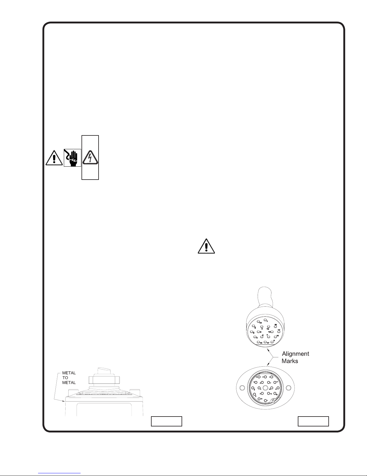
A fl at alignment mark is molded into the plug and mating
socket on the pump. These should be used as a visual
indication as to the correct orientation of the plug. Insert the
plug into the pump and install the two 12 mm socket head
cap screws into the clamping plate. Slowly tighten the two
screws alternating back and forth until the clamping plate is
drawn down fl ush to the top of the cord boss on the pump.
The two screws should be torqued until the plate is down to
a point where metal to metal contact is made between the
stainless steel plate and pump housing. (See Fig. 2)
FIGURE 2bFIGURE 2a
15
Page 16

16
MODELNOPART
NO
HP VOLT PH Hz
RPM
(Nom)
NEMA
START
CODE
FULL
LOAD
AMPS
1.2 SERVICE
FACTOR
AMPS
LOCKED
ROTOR
AMPS
CORD
P/N ▲
CORD
SIZE
CORD
O.D.
WINDING
RESISTANCE
MAIN - - START
3SHVR Pump
3SHVR5072 133701 5.0
208
1 60 3450
E 27.8 34.1 113.2
125498 8/4 - 18/4
1.12 ± .02 0.38 - - 1.66
230 G 25.4 29.9 131.2 1.12 ± .02 0.38 - - 1.66
3SHVR50N2 133702 5.0
208
3 60 3450 J
14.9 17.8
85.4 / 95.2
125496 12/4 - 18/4 .86 ± .02 0.75
230 13.7 16.0 125496 12/4 - 18/4 .86 ± .02 0.75
460 6.9 8.0 47.6 125497 12/4 - 18/4 .86 ± .02 3.00
3SHVR5052 133703 5.0 575 3 60 3450 J 5.5 6.4 38.1 125497 12/4 - 18/4 .86 ± .02 4.34
3SHVR75N2 133705 7.5
208
3 60 3450 M
24.2 28.0
173.9 / 201.0
125496 12/4 - 18/4 .86 ± .02 0.40
230 25.4 28.2 125496 12/4 - 18/4 .86 ± .02 0.40
460 12.7 14.1 100.5 125497 12/4 - 18/4 .86 ± .02 1.58
3SHVR7552 133706 7.5 575 3 60 3450 M 10.2 11.3 80.4 125497 12/4 - 18/4 .86 ± .02 2.47
3SHVR100N2 133707 10.0
208
3 60 3450 K
30.8 37.0
173.9 / 201.0
125498 8/4 - 18/4 1.12 ± .02 0.40
230 30.1 34.8 125498 8/4 - 18/4 1.12 ± .02 0.40
460 15.1 17.4 100.5 125497 12/4 - 18/4 .86 ± .02 1.58
3SHVR10052 133708 10.0 575 3 60 3450 K 12.1 13.9 80.4 125497 12/4 - 18/4 .86 ± .02 2.47
3SHVR2074 134236 2.0
208
1 60 1750
G 10.4 12.1 59.1 125496 12/4 - 18/4 .86 ± .02 0.88 - 2.14
230 J 10.7 11.9 66.3 125496 12/4 - 18/4 .86 ± .02 0.88 - 2.14
3SHVR20N4 134237 2.0
208
3 60 1750 P
7.4 8.3 58.2 125496 12/4 - 18/4 .86 ± .02 1.08
230 7.4 8.0 65.8 125496 12/4 - 18/4 .86 ± .02 1.08
460 3.7 4.0 32.9 125497 12/4 - 18/4 .86 ± .02 4.32
3SHVR2054 134238 2.0 575 3 60 1750 T 3.9 4.2 37.0 125497 12/4 - 18/4 .86 ± .02 4.32
3SHVR3074 134239 3.0
208
1 60 1750
D 14.9 18.5 59.1 125496 12/4 - 18/4 .86 ± .02 0.88 - 2.14
230 F 14.1 16.5 66.3 125496 12/4 - 18/4 .86 ± .02 0.88 - 2.14
3SHVR30N4 134240 3.0
208
3 60 1750 K
9.7 11.4 58.2 125496 12/4 - 18/4 .86 ± .02 1.08
230 9.2 10.6 65.8 125496 12/4 - 18/4 .86 ± .02 1.08
460 4.6 5.3 32.9 125497 12/4 - 18/4 .86 ± .02 4.32
3SHVR3054 134241 3.0 575 3 60 1750 N 4.5 4.9 37.0 125497 12/4 - 18/4 .86 ± .02 4.32
3SHVR5074 134242 5.0
208
1 60 1750
D 27.2 35.6 99.9 125498 8/4 - 18/4 1.12 ± .02 0.50 - - 2.66
230 F 25.4 30.2 112.4 125496 12/4 - 18/4 .86 ± .02 0.50 - - 2.66
3SHVR50N4 134243 5.0
208
3 60 1750 J
15.8 18.7 82.4 125496 12/4 - 18/4 .86 ± .02 0.72
230 15.0 17.2 92.4 125496 12/4 - 18/4 .86 ± .02 0.72
460 7.5 8.6 46.2 125497 12/4 - 18/4 .86 ± .02 2.88
3SHVR5054 134244 5.0 575 3 60 1750 J 6.0 6.9 37.0 125497 12/4 - 18/4 .86 ± .02 4.32
Moisture and Temperature sensor leads are integral to power cord.
W
inding Resistance ± 7.5% Winding resistance measured in OHMS @ 25°C (Between Lines) at motor leads.
Pump rated for operation at ± 10% voltage at motor.
▲ Cord Suffi x: XF - 50 Feet, XJ - 75 Feet, or XL - 100 Feet
▲ Cord sold separately (After March-2016 ONLY). Pumps built Before March-2016 refer to Cord Assembly Kit, see page 28.
CHART ‘A’
Page 17

17
MODELNOPART
NO
HP VOLT PH Hz
RPM
(Nom)
NEMA
START
CODE
FULL
LOAD
AMPS
1.2 SERVICE
FACTOR
AMPS
LOCKED
ROTOR
AMPS
CORD
P/N ▲
CORD
SIZE
CORD
O.D.
WINDING
RESISTANCE
MAIN - - START
3SHVRA Pump
3SHVRA2074 138194 2.0
208
1
60 1750 G 10.4 12.1 59.1 125496 12/4 - 18/4 .86 ± .02 0.88 -- 2.14
230 60 1750 J 10.7 11.9 66.3 125496 12/4 - 18/4 .86 ± .02 0.88 -- 2.14
3SHVRA20N4 138195 2.0
208
3
60 1750
P
7.4 8.3 58.2 125496 12/4 - 18/4 .86 ± .02 1.08
230 60 1750 7.4 8.0 65.8 125496 12/4 - 18/4 .86 ± .02 1.08
460 60 1750 3.7 4 32.9 125497 12/4 - 18/4 .86 ± .02 4.32
3SHVRA2054 138196 2.0 575 3 60 1750 T 3.9 4.2 37.0 125497 12/4 - 18/4 .86 ± .02 4.32
3SHVRA3074 138197 3.0
208
1
60 1750 D 14.9 18.5 37.0 125496 12/4 - 18/4 .86 ± .02 0.88 -- 2.14
230 60 1750 F 14.1 16.5 66.3 125496 12/4 - 18/4 .86 ± .02 0.88 -- 2.14
3SHVRA30N4 138198 3.0
208
3
60 1750
K
9.7 11.4 58.2 125496 12/4 - 18/4 .86 ± .02 1.08
230 60 1750 9.2 10.6 65.8 125496 12/4 - 18/4 .86 ± .02 1.08
460 60 1750 4.6 5.3 32.9 125497 12/4 - 18/4 .86 ± .02 4.32
3SHVRA3054 138199 3.0 575 3 60 1750 N 4.5 4.9 37.0 125497 12/4 - 18/4 .86 ± .02 4.32
3SHVRA5074 138200 5.0
208
1
60 1750 D 27.2 35.6 99.9 125498 8/4 - 18/4 1.12 ± .02 0.50 -- 2.66
230 60 1750 F 25.4 30.2 112.4 125498 12/4 - 18/4 .86 ± .02 0.50 -- 2.66
3SHVRA50N4 130201 5.0
208
3
60 1750
J
15.8 18.7 82.4 125496 12/4 - 18/4 .86 ± .02 0.72
230 60 1750 15 17.2 92.4 125496 12/4 - 18/4 .86 ± .02 0.72
460 60 1750 7.5 8.6 46.2 125497 12/4 - 18/4 .86 ± .02 2.88
3SHVRA5054 130202 5.0 575 3 60 1750 J 6 6.9 37.0 125497 12/4 - 18/4 .86 ± .02 4.32
3SHVRA75N4 130203 7.5
208
3
60 1750
H
23.8 28.5 105.9 125496 12/4 - 18/4 .86 ± .02 0.43
230 60 1750 23.7 27.2 123.6 125496 12/4 - 18/4 .86 ± .02 0.43
460 60 1750 11.9 13.6 61.8 125497 12/4 - 18/4 .86 ± .02 1.72
3SHVRA7554 138204 7.5 575 3 60 1750 H 9.5 10.9 49.4 125497 12/4 - 18/4 .86 ± .02 2.69
Moisture and Temperature sensor leads are integral to power cord.
W
inding Resistance ± 7.5% Winding resistance measured in OHMS @ 25°C (Between Lines) at motor leads.
Pump rated for operation at ± 10% voltage at motor.
▲ Cord Suffi x: XF - 50 Feet, XJ - 75 Feet, or XL - 100 Feet
▲ Cord sold separately (After March-2016 ONLY). Pumps built Before March-2016 refer to Cord Assembly Kit, see page 28.
CHART ‘B’
Page 18

18
MODELNOPART
NO
HP VOLT PH Hz
RPM
(Nom)
NEMA
START
CODE
FULL
LOAD
AMPS
1.2 SERVICE
FACTOR
AMPS
LOCKED
ROTOR
AMPS
CORD
P/N ▲
CORD
SIZE
CORD
O.D.
WINDING
RESISTANCE
MAIN - - START
3SHMP Pump
3SHMP2074 133681 2.0
208
1 60 1750
G 10.4 12.1 59.1
125496 12/4 - 18/4
.86 ± .02 0.88 - 2.14
230 J 10.7 11.9 66.3 .86 ± .02 0.88 - 2.14
3SHMP20N4 133682 2.0
208
3 60 1750 P
7.4 8.3
58.2 / 65.8
125496 12/4 - 18/4 .86 ± .02 1.08
230 7.4 8.0 125496 12/4 - 18/4 .86 ± .02 1.08
460 3.7 4.0 32.9 125497 12/4 - 18/4 .86 ± .02 4.32
3SHMP2054 133683 2.0 575 3 60 1750 T 3.9 4.2 37.0 125497 12/4 - 18/4 .86 ± .02 4.32
3SHMP3074 133684 3.0
208
1 60 1750
D 14.9 18.5 59.1
125496 12/4 - 18/4
.86 ± .02 0.88 - 2.14
230 F 14.1 16.5 66.3 .86 ± .02 0.88 - 2.14
3SHMP30N4 133685 3.0
208
3 60 1750 K
9.7 11.4
58.2 / 65.8
125496 12/4 - 18/4 .86 ± .02 1.08
230 9.2 10.6 125496 12/4 - 18/4 .86 ± .02 1.08
460 4.6 5.3 32.9 125497 12/4 - 18/4 .86 ± .02 4.32
3SHMP3054 133686 3.0 575 3 60 1750 N 4.5 4.9 37.0 125497 12/4 - 18/4 .86 ± .02 4.32
3SHMP5074 133687 5.0
208
1 60 1750
D 27.2 35.6 99.9
125498 8/4 - 18/4
1.12 ± .02 0.50 - - 2.66
230 F 25.4 30.2 112.4 1.12 ± .02 0.50 - - 2.66
3SHMP50N4 133688 5.0
208
3 60 1750 J
15.8 18.7
82.4 / 92.4
125496 12/4 - 18/4 .86 ± .02 0.72
230 15.0 17.2 125496 12/4 - 18/4 .86 ± .02 0.72
460 7.5 8.6 46.2 125497 12/4 - 18/4 .86 ± .02 2.88
3SHMP5054 133689 5.0 575 3 60 1750 J 6.0 6.9 37.0 125497 12/4 - 18/4 .86 ± .02 4.32
3SHMPA Pump
3SHMPA3074 137498 3.0
208
1 60 1750
D 14.9 18.5 59.1
125496 12/4 - 18/4 .86 ± .02 0.88 - 2.14
230 F 14.1 16.5 66.3
3SHMPA30N4 137499 3.0
208
3 60 1750 K
9.7 11.4
58.2 / 65.8 125496
12/4 - 18/4 .86 ± .02
1.08
230 9.2 10.6 1.08
460 4.6 5.3 32.9 125497 4.32
3SHMPA3054 137500 3.0 575 3 60 1750 N 4.5 4.9 37.0 125497 12/4 - 18/4 .86 ± .02 4.32
3SHMPA5074 137501 5.0
208
1 60 1750
D 27.2 35.6 99.9
125498 8/4 - 18/4 1.12 ± .02
0.50 -- 2.66
230 F 25.4 30.2 112.4 0.50 -- 2.66
3SHMPA50N4 137502 5.0
208
3 60 1750 J
15.8 18.7
82.4 / 92.4 125496
12/4 - 18/4 .86 ± .02
0.72
230 15.0 17.2 0.72
460 7.5 8.6 46.2 125497 2.88
3SHMPA5054 137503 5.0 575 3 60 1750 J 6.0 6.9 37.0 125497 12/4 - 18/4 .86 ± .02 4.32
3SHMPA75N4 137940 7.5
208
3 60 1750 H
23.8 28.5
105.9 / 123.6 125496
12/4 - 18/4 .86 ± .02
0.43
230 23.7 27.2 0.43
460 11.9 13.6 61.8 125497 1.72
3SHMPA7554 137941 7.5 575 3 60 1750 H 9.5 10.9 49.4 125497 12/4 - 18/4 .86 ± .02 2.69
Moisture and Temperature sensor leads are integral to power cord.
W
inding Resistance ± 7.5% Winding resistance measured in OHMS @ 25°C (Between Lines) at motor leads.
Pump rated for operation at ± 10% voltage at motor.
▲ Cord Suffi x: XF - 50 Feet, XJ - 75 Feet, or XL - 100 Feet
▲ Cord sold separately (After March-2016 ONLY). Pumps built Before March-2016 refer to Cord Assembly Kit, see page 28.
CHART ‘C’
Page 19

19
MODELNOPART
NO
HP VOLT PH Hz
RPM
(Nom)
NEMA
START
CODE
FULL
LOAD
AMPS
1.2 SERVICE
FACTOR
AMPS
LOCKED
ROTOR
AMPS
CORD
P/N ▲
CORD
SIZE
CORD
O.D.
WINDING
RESISTANCE
MAIN - - START
4SHVA Pump
4SHVA75N2 133650 7.5
208
3 60 3450 M
24.2 28.0
173.9 / 201.0
125496 12/4 - 18/4 .86 ± .02 0.40
230 25.4 28.2 125496 12/4 - 18/4 .86 ± .02 0.40
460 12.7 14.1 100.5 125497 12/4 - 18/4 .86 ± .02 1.58
4SHVA7552 133651 7.5 575 3 60 3450 M 10.2 11.3 80.4 125497 12/4 - 18/4 .86 ± .02 2.47
4SHVA100N2 133652 10.0
208
3 60 3450 K
30.8 37.0
173.9 / 201.0
125498 8/4 - 18/4 1.12 ± .02 0.40
230 30.1 34.8 125498 8/4 - 18/4 1.12 ± .02 0.40
460 15.1 17.4 100.5 125497 12/4 - 18/4 .86 ± .02 1.58
4SHVA10052 133653 10.0 575 3 60 3450 K 12.1 13.9 80.4 125497 12/4 - 18/4 .86 ± .02 2.47
4SHVA2074 134212 2.0
208
1 60 1750
G 10.4 12.1 59.1 125496 12/4 - 18/4 .86 ± .02 0.88 - 2.14
230 J 10.7 11.9 66.3 125496 12/4 - 18/4 .86 ± .02 0.88 - 2.14
4SHVA20N4 134213 2.0
208
3 60 1750 P
7.4 8.3 58.2 125496 12/4 - 18/4 .86 ± .02 1.08
230 7.4 8.0 65.8 125496 12/4 - 18/4 .86 ± .02 1.08
460 3.7 4.0 32.9 125497 12/4 - 18/4 .86 ± .02 4.32
4SHVA2054 134214 2.0 575 3 60 1750 T 3.9 4.2 37.0 125497 12/4 - 18/4 .86 ± .02 4.32
4SHVA3074 134215 3.0
208
1 60 1750
D 14.9 118.5 59.1 125496 12/4 - 18/4 .86 ± .02 0.88 - 2.14
230 F 14.1 16.5 66.3 125496 12/4 - 18/4 .86 ± .02 0.88 - 2.14
4SHVA30N4 134216 3.0
208
3 60 1750 K
9.7 11.4 58.2 125496 12/4 - 18/4 .86 ± .02 1.08
230 9.2 10.6 65.8 125496 12/4 - 18/4 .86 ± .02 1.08
460 4.6 5.3 32.9 125497 12/4 - 18/4 .86 ± .02 4.32
4SHVA3054 134217 3.0 575 3 60 1750 N 4.5 4.9 37.0 125497 12/4 - 18/4 .86 ± .02 4.32
4SHVA5074 134218 5.0
208
1 60 1750
D 27.2 35.6 99.9 125498 8/4 - 18/4 1.12 ± .02 0.50 - - 2.66
230 F 25.4 30.2 112.4 125496 12/4 - 18/4 .86 ± .02 0.50 - - 2.66
4SHVA50N4 134219 5.0
208
3 60 1750 J
15.8 18.7 82.4 125496 12/4 - 18/4 .86 ± .02 0.72
230 15.0 17.2 92.4 125496 12/4 - 18/4 .86 ± .02 0.72
460 7.5 8.6 46.2 125497 12/4 - 18/4 .86 ± .02 2.88
4SHVA5054 134220 5.0 575 3 60 1750 J 6.0 6.9 37.0 125497 12/4 - 18/4 .86 ± .02 4.32
Moisture and Temperature sensor leads are integral to power cord.
W
inding Resistance ± 7.5% Winding resistance measured in OHMS @ 25°C (Between Lines) at motor leads.
Pump rated for operation at ± 10% voltage at motor.
▲ Cord Suffi x: XF - 50 Feet, XJ - 75 Feet, or XL - 100 Feet
▲ Cord sold separately (After March-2016 ONLY). Pumps built Before March-2016 refer to Cord Assembly Kit, see page 28.
CHART ‘D’
Page 20

20
MODELNOPART
NO
HP VOLT PH Hz
RPM
(Nom)
NEMA
START
CODE
FULL
LOAD
AMPS
1.2 SERVICE
FACTOR
AMPS
LOCKED
ROTOR
AMPS
CORD
P/N ▲
CORD
SIZE
CORD
O.D.
WINDING
RESISTANCE
MAIN - - START
4SHVB Pump
4SHVB75N2 133655 7.5
208
3 60 3450 M
24.2 28.0
173.9 / 201.0
125496 12/4 - 18/4 .86 ± .02 0.40
230 25.4 28.2 125496 12/4 - 18/4 .86 ± .02 0.40
460 12.7 14.1 100.5 125497 12/4 - 18/4 .86 ± .02 1.58
4SHVB7552 133656 7.5 575 3 60 3450 M 10.2 11.3 80.4 125497 12/4 - 18/4 .86 ± .02 2.47
4SHVB100N2 133657 10.0
208
3 60 3450 K
30.8 37.0
173.9 / 201.0
125498 8/4 - 18/4 1.12 ± .02 0.40
230 30.1 34.8 125498 8/4 - 18/4 1.12 ± .02 0.40
460 15.1 17.4 100.5 125497 12/4 - 18/4 .86 ± .02 1.58
4SHVB10052 133658 10.0 575 3 60 3450 K 12.1 13.9 80.4 125497 12/4 - 18/4 .86 ± .02 2.47
4SHVB2074 134221 2.0
208
1 60 1750
G 10.4 12.1 59.1 125496 12/4 - 18/4 .86 ± .02 0.88 - 2.14
230 J 10.7 11.9 66.3 125496 12/4 - 18/4 .86 ± .02 0.88 - 2.14
4SHVB20N4 134222 2.0
208
3 60 1750 P
7.4 8.3 58.2 125496 12/4 - 18/4 .86 ± .02 1.08
230 7.4 8.0 65.8 125496 12/4 - 18/4 .86 ± .02 1.08
460 3.7 4.0 32.9 125497 12/4 - 18/4 .86 ± .02 4.32
4SHVB2054 134223 2.0 575 3 60 1750 T 3.9 4.2 37.0 125497 12/4 - 18/4 .86 ± .02 4.32
4SHVB3074 134224 3.0
208
1 60 1750
D 14.9 18.5 59.1 125496 12/4 - 18/4 .86 ± .02 0.88 - 2.14
230 F 14.1 16.5 66.3 125496 12/4 - 18/4 .86 ± .02 0.88 - 2.14
4SHVB30N4 134225 3.0
208
3 60 1750 K
9.7 11.4 58.2 125496 12/4 - 18/4 .86 ± .02 1.08
230 9.2 10.6 65.8 125496 12/4 - 18/4 .86 ± .02 1.08
460 4.6 5.3 32.9 125497 12/4 - 18/4 .86 ± .02 4.32
4SHVB3054 134226 3.0 575 3 60 1750 N 4.5 4.9 37.0 125497 12/4 - 18/4 .86 ± .02 4.32
4SHVB5074 134227 5.0
208
1 60 1750
D 27.2 35.6 99.9 125498 8/4 - 18/4 1.12 ± .02 0.50 - - 2.66
230 F 25.4 30.2 112.4 125496 12/4 - 18/4 .86 ± .02 0.50 - - 2.66
4SHVB50N4 134228 5.0
208
3 60 1750 J
15.8 18.7 82.4 125496 12/4 - 18/4 .86 ± .02 0.72
230 15.0 17.2 92.4 125496 12/4 - 18/4 .86 ± .02 0.72
460 7.5 8.6 46.2 125497 12/4 - 18/4 .86 ± .02 2.88
4SHVB5054 134229 5.0 575 3 60 1750 J 6.0 6.9 37.0 125497 12/4 - 18/4 .86 ± .02 4.32
4SHVB75N4 134230 7.5
208
3 60 1750 H
23.8 28.5 105.9 125496 12/4 - 18/4 .86 ± .02 0.43
230 23.7 27.2 123.6 125496 12/4 - 18/4 .86 ± .02 0.43
460 11.9 13.6 61.8 125497 12/4 - 18/4 .86 ± .02 1.72
4SHVB7554 134231 7.5 575 3 60 1750 H 9.5 10.9 49.4 125497 12/4 - 18/4 .86 ± .02 2.69
4SHVB100N4 134232 10.0
208
3 60 1750 E
32.2 41.4 105.9 125498 8/4 - 18/4 .86 ± .02 0.43
230 29.8 35.6 123.6 125498 8/4 - 18/4 1.12 ± .02 0.43
460 14.9 17.8 61.8 125497 12/4 - 18/4 .86 ± .02 1.72
4SHVB10054 134233 10.0 575 3 60 1750 E 11.9 14.2 49.4 125497 12/4 - 18/4 .86 ± .02 2.69
Moisture and Temperature sensor leads are integral to power cord.
Winding Resistance ± 7.5% Winding resistance measured in OHMS @ 25°C (Between Lines) at motor leads.
Pump rated for operation at ± 10% voltage at motor.
▲ Cord Suffi x: XF - 50 Feet, XJ - 75 Feet, or XL - 100 Feet
▲ Cord sold separately (After March-2016 ONLY). Pumps built Before March-2016 refer to Cord Assembly Kit, see page 28.
CHART ‘E’
Page 21

21
MODELNOPART
NO
HP VOLT PH Hz
RPM
(Nom)
NEMA
START
CODE
FULL
LOAD
AMPS
SERVICE
FACTOR
SERVICE
FACTOR
AMPS
LOCKED
ROTOR
AMPS
CORD
P/N ▲
CORD
SIZE
CORD
O.D.
WINDING
RESISTANCE
MAIN - - START
4SHVBA Pump
4SHVBA5074 139982* 5.0
208
1 60 1750
D 27.2 1.2 35.6 99.9 125498 8/4 - 18/4 1.12 ± .02 0.50 - 2.66
230 F 25.4 1.2 30.2 112.4 125496 12/4 - 18/4 .86 ± .02 0.50 - 2.66
4SHVBA50N4 139983* 5.0
208
3 60 1750 J
15.8 1.2 18.7 82.4 125496 12/4 - 18/4 .86 ± .02 0.72
230 15.0 1.2 17.2 92.4 125496 12/4 - 18/4 .86 ± .02 0.72
460 7.5 1.2 8.6 46.2 125497 12/4 - 18/4 .86 ± .02 2.88
4SHVBA5054 139984* 5.0 575 3 60 1750 J 6.0 1.2 6.9 37.0 125497 12/4 - 18/4 .86 ± .02 4.32
4SHVBA75N4 138953 7.5
208
3 60 1750 H
23.8 1.2 28.5 105.9 125496 12/4 - 18/4 .86 ± .02 0.43
230 23.7 1.2 27.2 123.6 125496 12/4 - 18/4 .86 ± .02 0.43
460 11.9 1.2 13.6 61.8 125497 12/4 - 18/4 .86 ± .02 1.72
4SHVBA7554 138954 7.5 575 3 60 1750 H 9.5 1.2 10.9 49.4 125497 12/4 - 18/4 .86 ± .02 2.69
4SHVBA100N4 138955 10.0
208
3 60 1750 E
32.2 1.2 41.4 105.9 125498 8/4 - 18/4 1.12 ± .02 0.43
230 29.8 1.2 35.6 123.6 125498 8/4 - 18/4 1.12 ± .02 0.43
460 14.9 1.2 17.8 61.8 125497 12/4 - 18/4 .86 ± .02 1.72
4SHVBA10054 138956 10.0 575 3 60 1750 E 11.9 1.2 14.2 49.4 125497 12/4 - 18/4 .86 ± .02 2.69
Moisture and Temperature sensor leads are integral to power cord.
Winding Resistance ± 7.5% Winding resistance measured in OHMS @ 25°C (Between Lines) at motor leads.
Pump rated for operation at ± 10% voltage at motor.
▲ Cord Suffi x: XF - 50 Feet, XJ - 75 Feet, or XL - 100 Feet
▲ Cord sold separately (After March-2016 ONLY). Pumps built Before March-2016 refer to Cord Assembly Kit, see page 28.
* Select impeller diameter when ordering.
CHART ‘F’
Page 22

22
MODELNOPART
NO
HP VOLT PH Hz
RPM
(Nom)
NEMA
START
CODE
FULL LOAD
AMPS
1.2 SERVICE
FACTOR
AMPS
LOCKED
ROTOR
AMPS
CORD
P/N ▲
CORD
SIZE
CORD
O.D.
WINDING
RESISTANCE
MAIN - - START
4SHMS Pump
4SHMS3074 133659 3.0
208
1 60 1750
D 14.9 18.5 59.1
125496 12/4 - 18/4
.86 ± .02 0.88 - - 2.14
230 F 14.1 16.5 66.3 .86 ± .02 0.88 - - 2.14
4SHMS30N4 133660 3.0
208
3 60 1750 K
9.7 11.4
58.2 / 65.8
125496 12/4 - 18/4 .86 ± .02 1.08
230 9.2 10.6 125496 12/4 - 18/4 .86 ± .02 1.08
460 4.6 5.3 32.9 125497 12/4 - 18/4 .86 ± .02 4.32
4SHMS3054 133661 3.0 575 3 60 1750 N 4.5 4.9 37.0 125497 12/4 - 18/4 .86 ± .02 4.32
4SHMS5074 133662 5.0
208
1 60 1750
D 27.2 35.6 99.9
125498 8/4 - 18/4
1.12 ± .02 0.50 - - 2.66
230 F 25.4 30.2 112.4 1.12 ± .02 0.50 - - 2.66
4SHMS50N4 133663 5.0
208
3 60 1750 J
15.8 18.7
82.4 / 92.4
125496 12/4 - 18/4 .86 ± .02 0.72
230 15.0 17.2 125496 12/4 - 18/4 .86 ± .02 0.72
460 7.5 8.6 46.2 125497 12/4 - 18/4 .86 ± .02 2.88
4SHMS5054 133664 5.0 575 3 60 1750 J 6.0 6.9 37.0 125497 12/4 - 18/4 .86 ± .02 4.32
4SHMS75N4 133666 7.5
208
3 60 1750 H
23.8 28.5
105.9 / 123.6
125496 12/4 - 18/4 .86 ± .02 0.43
230 23.7 27.2 125496 12/4 - 18/4 .86 ± .02 0.43
460 11.9 13.6 61.8 125497 12/4 - 18/4 .86 ± .02 1.72
4SHMS7554 133667 7.5 575 3 60 1750 H 9.5 10.9 49.4 125497 12/4 - 18/4 .86 ± .02 2.69
4SHMC Pump
4SHMC5074 133641 5.0
208
1 60 1750
D 27.2 35.6 99.9
125498 8/4 - 18/4
1.12 ± .02 0.50 - - 2.66
230 F 25.4 30.2 112.4 1.12 ± .02 0.50 - - 2.66
4SHMC50N4 133642 5.0
208
3 60 1750 J
15.8 18.7
82.4/92.4
125496 12/4 - 18/4 .86 ± .02 0.72
230 15.0 17.2 125496 12/4 - 18/4 .86 ± .02 0.72
460 7.5 8.6 46.2 125497 12/4 - 18/4 .86 ± .02 2.88
4SHMC5054 133643 5.0 575 3 60 1750 J 6.0 6.9 37.0 125497 12/4 - 18/4 .86 ± .02 4.32
4SHMC75N4 133645 7.5
208
3 60 1750 H
23.8 28.5
105.9 / 123.6
125496 12/4 - 18/4 .86 ± .02 0.43
230 23.7 27.2 125496 12/4 - 18/4 .86 ± .02 0.43
460 11.9 13.6 61.8 125497 12/4 - 18/4 .86 ± .02 1.72
4SHMC7554 133646 7.5 575 3 60 1750 H 9.5 10.9 49.4 125497 12/4 - 18/4 .86 ± .02 2.69
4SHMC100N4 133647 10.0
208
3 60 1750 E
32.2 41.4
105.9 / 123.6
125498
8/4 - 18/4
1.12 ± .02 0.43
230 29.8 35.6 125498 1.12 ± .02 0.43
460 14.9 17.8 61.8 125497 12/4 - 18/4 .86 ± .02 1.72
4SHMC10054 133648 10.0 575 3 60 1750 E 11.9 14.2 49.4 125497 12/4 - 18/4 .86 ± .02 2.69
Moisture and Temperature sensor leads are integral to power cord.
W
inding Resistance ± 7.5% Winding resistance measured in OHMS @ 25°C (Between Lines) at motor leads.
Pump rated for operation at ± 10% voltage at motor.
▲ Cord Suffi x: XF - 50 Feet, XJ - 75 Feet, or XL - 100 Feet
▲ Cord sold separately (After March-2016 ONLY). Pumps built Before March-2016 refer to Cord Assembly Kit, see page 28.
CHART ‘G’
Page 23

23
MODELNOPART
NO
HP VOLT PH Hz
RPM
(Nom)
NEMA
START
CODE
FULL
LOAD
AMPS
1.2 SERVICE
FACTOR
AMPS
LOCKED
ROTOR
AMPS
CORD
P/N ▲
CORD
SIZE
CORD
O.D.
WINDING
RESISTANCE
MAIN - - START
4SHDF Pump
4SHDF3074 133670 3.0
208
1 60 1750
D 14.9 18.5 59.1
125496 12/4 - 18/4
.86 ± .02 0.88 - - 2.14
230 F 14.1 16.5 66.3 .86 ± .02 0.88 - - 2.14
4SHDF30N4 133671 3.0
208
3 60 1750 K
9.7 11.4
58.2 / 65.8
125496 12/4 - 18/4 .86 ± .02 1.08
230 9.2 10.6 125496 12/4 - 18/4 .86 ± .02 1.08
460 4.6 5.3 32.9 125497 12/4 - 18/4 .86 ± .02 4.32
4SHDF3054 133672 3.0 575 3 60 1750 N 4.5 4.9 37.0 125497 12/4 - 18/4 .86 ± .02 4.32
4SHDF5074 133673 5.0
208
1 60 1750
D 27.2 35.6
99.9 / 112.4 125498 8/4 - 18/4
1.12 ± .02 0.50 - - 2.66
230 F 25.4 30.2 1.12 ± .02 0.50 - - 2.66
4SHDF50N4 133674 5.0
208
3 60 1750 J
15.8 18.7
82.4 / 92.4
125496 12/4 - 18/4 .86 ± .02 0.72
230 15.0 17.2 125496 12/4 - 18/4 .86 ± .02 0.72
460 7.5 8.6 46.2 125497 12/4 - 18/4 .86 ± .02 2.88
4SHDF5054 133675 5.0 575 3 60 1750 J 6.0 6.9 37.0 125497 12/4 - 18/4 .86 ± .02 4.32
4SHDF75N4 133677 7.5
208
3 60 1750 H
23.8 28.5
105.9 / 123.6
125496 12/4 - 18/4 .86 ± .02 0.43
230 23.7 27.2 125496 12/4 - 18/4 .86 ± .02 0.43
460 11.9 13.6 61.8 125497 12/4 - 18/4 .86 ± .02 1.72
4SHDF7554 133678 7.5 575 3 60 1750 H 9.5 10.9 49.4 125497 12/4 - 18/4 .86 ± .02 2.69
4SHDF100N4 133679 10.0
208
3 60 1750 E
32.2 41.4
105.9 / 123.6
125498
8/4 - 18/4
1.12 ± .02 0.43
230 29.8 35.6 125498 1.12 ± .02 0.43
460 14.9 17.8 61.8 125497 12/4 - 18/4 .86 ± .02 1.72
4SHDF10054 133680 10.0 575 3 60 1750 E 11.9 14.2 49.4 125497 12/4 - 18/4 .86 ± .02 2.69
4SHDG Pump
4SHDG5074 133633 5.0
208
1 60 1750
D 27.2 35.6 99.9
125498 8/4 - 18/4
1.12 ± .02 0.50 - - 2.66
230 F 25.4 30.2 112.4 1.12 ± .02 0.50 - - 2.66
4SHDG50N4 133634 5.0
208
3 60 1750 J
15.8 18.7
82.4 / 92.4
125496 12/4 - 18/4 .86 ± .02 0.72
230 15.0 17.2 125496 12/4 - 18/4 .86 ± .02 0.72
460 7.5 8.6 46.2 125497 12/4 - 18/4 .86 ± .02 2.88
4SHDG5054 133635 5.0 575 3 60 1750 J 6.0 6.9 37.0 125497 12/4 - 18/4 .86 ± .02 4.32
4SHDG75N4 133637 7.5
208
3 60 1750 H
23.8 28.5
105.9 / 123.6
125496 12/4 - 18/4 .86 ± .02 0.43
230 23.7 27.2 125496 12/4 - 18/4 .86 ± .02 0.43
460 11.9 13.6 61.8 125497 12/4 - 18/4 .86 ± .02 1.72
4SHDG7554 133638 7.5 575 3 60 1750 H 9.5 10.9 49.4 125497 12/4 - 18/4 .86 ± .02 2.69
4SHDG100N4 133639 10.0
208
3 60 1750 E
32.2 41.4
105.9 / 123.6
125498
8/4 - 18/4
1.12 ± .02 0.43
230 29.8 35.6 125498 1.12 ± .02 0.43
460 14.9 17.8 61.8 125497 12/4 - 18/4 .86 ± .02 1.72
4SHDG10054 133640 10.0 575 3 60 1750 E 11.9 14.2 49.4 125497 12/4 - 18/4 .86 ± .02 2.69
Moisture and Temperature sensor leads are integral to power cord.
W
inding Resistance ± 7.5% Winding resistance measured in OHMS @ 25°C (Between Lines) at motor leads.
Pump rated for operation at ± 10% voltage at motor.
▲ Cord Suffi x: XF - 50 Feet, XJ - 75 Feet, or XL - 100 Feet
▲ Cord sold separately (After March-2016 ONLY). Pumps built Before March-2016 refer to Cord Assembly Kit, see page 28.
CHART ‘H’
Page 24

THREE PHASE 460-575 VOLT AC (orange molded plug)
Power Cable Motor Lead ID
Green (Ground) Green
Black 1
Red 2
White 3
Jumpered Inside Cord
Automatically (No user jumpering required)
T4 & T7 Together
T5 & T8 Together
T6 & T9 Together
THREE PHASE 208-230 VOLT AC (black molded plug)
Power Cable Motor Lead ID
Green (Ground) Green
Black 1
Red 2
White 3
Jumpered Inside Cord
Automatically (No user
jumpering required)
T4, T5 & T6 Together
T11 & T7 Together
T13 & T9 Together
T12 & T8 Together
MOISTURE AND TEMPERATURE SENSORS
Power Cable Lead ID
Brown P1 (Temperature Sensor)
Yellow P2 (Temperature Sensor)
Orange W1 (Moisture Sensor)
Blue W2 (Moisture Sensor)
SINGLE PHASE 208-230 VOLT AC (black molded plug)
Power Cable Motor Lead ID
Green (Ground) Green
Black 1 (Run)
Red 2 (Start)
White 3 (Common)
Jumpered Inside Cord
Automatically (No user
jumpering required)
T4, T5 & T6 Together
T11 & T7 Together
T13 & T9 Together
T12 & T8 Together
* Requires Start/Run Caps and Start Relay in panel *
External Ground Note:
(Grd symbol) An external ground screw is provided on the side of the motor cap which can be
used for supplemental bonding connection where local codes permit or require such connection.
FIGURE 3
24
Page 25

TYPICAL POWER CIRCUIT
HP RPM Cap Kit Start Relay Start Cap Run Cap
5 1750 133042 Mars 64 440MFD @ 330V 50MFD @370V
5 3450
2 1750
Single Phase Start Components
FIGURE 3b
Single Phase Cap Chart
133043 Mars 64 177MFD @ 330V 40MFD @440V3 1750
25
Page 26

TYPICAL THERMAL PROTECTION WIRING DIAGRAM
FIGURE 4
C-4.3) Overload Protection:
Current sensing overloads must be provided in the pump
control panel and should be properly sized for the full load
current of the pump. Three normally closed (N/C) thermal
sensors wired in series (one per phase) are embedded in
the motor windings and will detect excessive heat in the
event an overload condition occurs which will then trip and
stop the pump when wired in series with the pump contactor
control circuit. The thermal sensor leads marked P1 and
P2 MUST be connected in series with the stop button of
the pilot circuit of the magnetic motor controller located in
the control panel so that the thermostat will open the circuit
before dangerous temperatures are reached. A manual
momentary start switch is required to prevent the automatic
restarting of the motor when the thermostat resets. For a
typical wiring diagram, refer to Figure 4.
In the event of an over temperature condition, the source
of this condition should be determined and rectifi ed before
the pump is put back into normal operation. DO NOT LET
THE PUMP CYCLE OR RUN IF AN OVER TEMPERATURE
CONDITION OCCURS!
If current through the temperature sensor exceeds the values
listed, an intermediate control circuit relay must be used to
reduce the current or the sensor will not work properly.
TEMPERATURE SENSOR ELECTRICAL RATINGS
Volts Continuous
Amperes
110-120 3.00 20.0
220-240 2.00 18.0
Inrush
Amperes
C-4.4) Moisture Sensors:
A normally open (N/O) detector is installed in the pump seal
chamber, which will detect any moisture present, and a
continuity test resistor built into the motor. The test resistor
is rated 1 watt at 330K ohms. The moisture sensors MUST
be connected to moisture detector control in the control
panel which includes a continuity test circuit, see Figure
4 for typical wiring diagram. The normally closed (N/C)
contact of the moisture detector MUST be connected in
series with the stop button of the pilot circuit of the magnetic
motor controller. Wiring must be provided from the moisture
detector sensor probe leads of the motor designated W1
and W2 to terminals 9 and 10 of the 2800-XXX control.
Terminal pair 1-2 must be continuously energized from an
A-C supply line of electrical characteristics shown on the
data table. In the event of moisture detection, the pump
should be pulled and the source of the failure located and
repaired. IF MOISTURE DETECTION HAS OCCURRED,
SCHEDULE MAINTENANCE AS SOON AS POSSIBLE !
C-4.5) Control Panel and Electrical System:
The control panel and the electrical system MUST be
properly designed and wired to include at least, but not
limited to the following;
a. Proper grounding per NEC.
b. A temperature sensing circuit (See Fig. 4)
c. A moisture detection circuit with continuity test
circuit (See Fig. 5)
d. A level control system.
e. A main power manual disconnect and lock out.
f. A motor starter and overload system.
g. Start Capacitor, Run Capacitor & Start Relay
(single phase only).
26
Page 27

FIGURE 5
It is advisable that all three phase control panels be
purchased from the factory.
SECTION: D START-UP OPERATION
D-1) Check Voltage and Phase:
Before operating pump, compare the voltage and phase
information stamped on the pump’s identifi cation plate to the
available power.
D-2) Check Pump Rotation:
Before putting pump into service for the fi rst time, the motor
rotation must be checked. Improper motor rotation can result
in poor pump performance and can damage the motor and/
or pump. To check the rotation, suspend the pump freely,
momentarily apply power and observe the “kickback”.
“Kickback” should always be in a counter-clockwise direction
as viewed from the top of the pump motor housing and will
always be in the opposite direction of the rotation arrows
cast in the pump volute.
D-2.1) Incorrect Rotation for Three-Phase Pumps:
In the event that the rotation is incorrect for a three-phase
installation, interchange any two power cable leads at
the control box. Recheck the “kickback” rotation again by
momentarily applying power.
D-2.2) Test Procedure For Moisture Sensor Control:
With a moisture detection control, a normally closed push
button and neon indicating lamp is typically provided as a
means of checking the moisture sensing components. When
the push button is depressed, the indicating lamp will be
illuminated to indicate (A) power is supplied to the control,
(B) the control is operative, and (C) wiring to the moisture
sensing probes in the motor is intact. This procedure should
be performed periodically to confi rm integrity of the circuit.
D-3) Start-Up Report:
Included at the end of this manual is one start-up report
sheet, this sheet is to be completed as applicable. Return
a copy to Barnes and store the second in the control panel
or with the pump manual. It is important to record this data
at initial start-up since it will be useful to refer to should
servicing the pump be required in the future.
D-3.1) Identifi cation Plate:
Record the numbers from the pump’s identifi cation plate on
the START-UP REPORT provided at the end of the manual
for future reference.
27
Page 28

D-3.2) Insulation Test:
Before the pump is put into service, an insulation (megger)
test should be performed on the motor. The resistance values
(ohms) as well as the voltage (volts) and current (amps)
should be recorded on the start-up report. Pumps/systems
with an insulation value of less than 5 M-Ohms should
be investigated for moisture or damaged cables before
proceeding.
3. If oil is found to be clean and uncontaminated (measure
above 15 KV. breakdown), refi ll the seal chamber as per
section F-1.2.
4. If oil is found to be dirty or contaminated (or measures
below 15 KV. breakdown), the pump must be carefully
inspected for leaks at the shaft seal (4), before refi lling
with oil. To locate the leak, perform a pressure test as per
section F-1.3. After leak is repaired, refi ll with new oil as
per section F-1.2.
D-3.3) Pump-Down Test:
After the pump has been properly wired and lowered into the
basin, sump or lift station, it is advisable to check the system
by fi lling with liquid and allowing the pump to operate through
it’s pumping cycle. The time needed to empty the system, or
pump-down time along with the volume of water, should be
recorded on the start-up report.
SECTION E: PREVENTATIVE MAINTENANCE
As the motor and seal chamber are oil-fi lled, no lubrication or
other maintenance is required, and generally Barnes Pumps
will give very reliable service and can be expected to operate
for years of normal sewage pumping without failing. However,
as with any mechanical piece of equipment a preventive
maintenance program is recommended and suggested to
include the following checks:
1) Test moisture detector control “Test Switch” for
continuity of circuit. Water in the seal chamber will
energize a seal leak warning light at the control
panel. This is a warning light only and does not
stop the motor. It indicates the seal has leaked
and must be repaired. This should be done within 2
or 3 weeks to prevent further damage. See section
D-2.2.
2) Inspect impeller and body for excessive build-up or
clogging and repair as required per section F-2.
3) Inspect outer shaft seal and replace as required per
section F-3.
4) Check motor for ground leakage and proper amp
draw.
F-1.2) Replacing Oil:
Seal Chamber - Drain all oil from seal chamber and dispose
of properly. Refi ll with (see parts list for amount) new cooling
oil as per Table 1. An air space must remain to compensate
for oil expansion (See Fig. 9). Set unit on side and fi ll.
IMPORANT! - Do not over" ll oil. Over" lling
of seal chamber with oil can create
excessive and dangerous hydraulic
pressure which can destroy the pump
and create a hazard. Over" lling oil voids
warranty.
F-1.3) Pressure Test:
Seal Chamber - Before checking the pump for leaks around
the shaft seal, the oil level should be full. Remove pipe plug.
Apply pipe sealant to pressure gauge assembly and tighten
into pipe plug hole. Pressurize motor housing to 10 P.S.I.
Use a soap solution around the sealed area and inspect
joints for “air bubbles”. If, after fi ve minutes, the pressure
is still holding constant, and no “bubbles” are observed,
slowly bleed the pressure and remove the gauge assembly.
Replace the pipe plug using a sealant. If the pressure does
not hold, then the leak must be located.
CAUTION! - Pressure builds up extremely
fast, increase pressure by “tapping” air
nozzle. Too much pressure will damage
seal. Do Not exceed 10 P.S.I. in seal
chamber.
SECTION F: SERVICE AND REPAIR
NOTE: All item numbers in ( ) refer to Figures 9 & 10.
WARNING ! - Electrical power to the pump
motors must be disconnected and locked
out to prevent any dangerous electrical
hazards or personnel danger before any
service work is done to the pump.
CAUTION ! - Operating pump
builds up heat and pressure;
allow time for pump to cool
to room temperature before
handling or servicing.
F-1) Lubrication
F-1.1) Checking Oil
1. Place pump on it’s side, and drain oil into a clean, dry
container.
2. Check oil for contamination using an oil tester with a range
to 30Kilovolts breakdown.
TABLE 1 - COOLING OIL - Dielectric
SUPPLIER GRADE
BP Enerpar SE100
Conoco Pale Paraffi n 22
Mobil D.T.E. Oil Light
G & G Oil Circulating 22
Imperial Oil Voltesso-35
Shell Canada Transformer-10
Texaco Diala-Oil-AX
Woco Premium 100
28
Page 29

F-2) Impeller and Volute Service:
F-2.1) Disassembly and Inspection:
To clean out the volute (11), or clean out or replace impeller
(6), disconnect power, remove cap screws (2) then vertically
lift motor assembly from the pump body (11). Clean out
the volute, if necessary, clean and examine impeller (6) for
pitting or wear, replace if required. To remove Impeller (6),
remove cap screw (8) and washer (8A). The impeller is
keyed onto the shaft with a square key (7) and to remove,
pull impeller straight off the shaft using a wheel puller if
required. Inspect o-ring (9) and replace if cut or damaged.
Before reinstallation, check the motor shaft and impeller bore
for damage.
F-2.2) Reassembly:
To install impeller (6), apply a thin fi lm of oil to motor shaft
and slide impeller straight onto shaft, keeping keyways
lined up. Drive key (7) into keyway. Thread cap screw (8)
and washer (8A) into shaft and torque to 45 ft. lbs. Rotate
impeller to check for binding. Place o-ring (9) on seal plate
pilot diameter lining up holes and install impeller and motor
assembly onto volute (11). Loctite cap screws (2), insert
into volute and motor assembly and torque to 35 ft. lbs.
Check for free rotation of motor and impeller.
F-3) Outer Shaft Seal Service:
CAUTION ! - Handle seal parts with extreme care.
DO NOT scratch or mar lapped surfaces.
FIGURE 6
FIGURE 7
Stationary Member (4A) Polished Face Out
Motor Mounting Plate
Seal Pusher
F-3.1) Disassembly and Inspection:
To expose outer shaft seal (4) for examination, remove
Impeller and Volute per Section F-1.1. Set motor assembly
(1) in the inverted position to prevent loss of oil. Remove
snap ring from motor shaft, then retaining ring (5), spring
(4C) and rotating member (4B) from shaft, See Figure
5 Examine all seal parts and especially contact faces.
Inspect seal for signs of wear such as uneven wear pattern
on stationary members, chips and scratches on either seal
face. DO NOT interchange seal components, replace the
entire shaft seal (4). If replacing seal, remove stationary
(4A) from mounting plate by prying out with fl at screw
driver.
F-3.2) Reassembly:
Lightly oil (DO NOT use grease) outer surface of stationary
member (4A). Press stationary member (4A) fi rmly into
mounting plate using a seal pusher but the seal pusher is
to come in contact with seal face (See Fig. 7).
Make sure the stationary member is in straight and that
the rubber ring is not out of it’s groove. Lightly oil (DO NOT
use grease) shaft and inner surface of bellows on rotating
member (4B) see Figure 8. With lapped surface of rotating
member (4B) facing inward toward stationary member (4A),
slide rotating member (4B) onto shaft using a seal pusher,
until lapped faces of (4A) and (4B) are together. (See Fig.
8).
Motor
Stationary
Bullet
FIGURE 8
Rotating Member (4B)
Seal Pusher
IMPORTANT ! - It is extremely important to keep
seal faces clean during assembly. dirt particles
lodged between these faces will cause the seal
to leak.
Place spring (4C) over shaft and in place on rotating
member (4B), making sure it is seated on retainer and not
cocked or resting on bellows tail. Slide retaining ring (5)
over shaft and let rest on spring (4C). Replace snap ring
onto motor shaft. Inspect gasket (9) and replace if cut or
damaged. Assemble impeller and volute as outlined in
paragraph F-1.2.
29
Page 30

SECTION: G REPLACEMENT PARTS
G-1 ORDERING REPLACEMENT PARTS:
When ordering replacement parts, ALWAYS furnish the
following information:
1. Pump serial number and date code. (Paragraph G-4)
2. Pump model number. (Paragraph G-3)
3. Pump part number. (Paragraph G-2)
4. Part description.
5. Item part number.
6. Quantity required.
7. Shipping instructions.
8. Billing Instructions.
G-2 PART NUMBER:
This number is used for ordering and obtaining information.
G-3 MODEL NUMBER:
This designation consists of numbers and letters which
represent the discharge size, series, horsepower, motor
phase and voltage, speed and pump design. This number is
used for ordering and obtaining information.
G-4 SERIAL NUMBER:
The serial number block will consist of a six digit number,
which is specifi c to each pump and may be preceded by
an alpha character, which indicates the plant location. This
number will also be suffi xed with a four digit number, which
indicates the date the unit was built (Date Code).
EXAMPLE: A012345 0490.
Reference the six digit portion (Serial Number) of this
number when referring to the product.
30
Page 31

TROUBLE SHOOTING
CAUTION ! Always disconnect the pump from the electrical power source before handling.
If the system fails to operate properly, carefully read instructions and perform maintenance recommendations.
If operating problems persist, the following chart may be of assistance in identifying and correcting them:
MATCH “CAUSE” NUMBER WITH CORRELATING “CORRECTION” NUMBER.
NOTE: Not all problems and corrections will apply to each pump model.
PROBLEM CAUSE CORRECTION
Pump will not run 1
Pump will not turn off 2a. Float movement restricted.
Pump hums but does not run 1. Incorrect voltage
Pump delivers insuffi cient capacity 1. Incorrect voltage.
Pump cycles too frequently or runs
periodically when fi xtures are not in
use
Pump shuts off and turns on independent of switch, (trips thermal overload
protector). CAUTION! Pump may
start unexpectedly. Disconnect power
supply.
Pump operates noisily or vibrates
excessively
. Poor electrical connection, blown fuse,
tripped breaker or other interruption of power,
improper power supply.
2. Motor or switch inoperative (to isolate
cause, go to manual operation of pump).
2a. Float movement restricted.
2b. Switch will not activate pump or is defective.
2c. Defective motor
3. Insuffi cient liquid level.
2b. Switch will not activate pump or is defective.
4. Excessive infl ow or pump not properly sized
for application.
9. Pump may be airlocked
14. H-O-A switch on panel is in “HAND” position
8. Impeller jammed or loose on shaft, worn or
damaged, impeller cavity or inlet plugged.
4. Excessive infl ow or pump not properly sized
for application.
5. Discharge restricted.
6. Check valve stuck closed or installed backwards.
7. Shut-off valve closed.
8. Impeller jammed or loose on shaft, worn or
damaged, impeller cavity or inlet plugged.
9. Pump may be airlocked.
10. Pump running backwards
6. Check valve stuck closed or installed
backwards.
11. Fixtures are leaking.
15. Ground water entering basin.
1. Incorrect voltage.
4. Excessive infl ow or pump not properly sized
for application.
8. Impeller jammed, loose on shaft, worn or
damaged, impeller cavity or inlet plugged.
12. Excessive water temperature.
(internal protection only)
2c. Worn bearings, motor shaft bent.
5. Debris in impeller cavity or broken impeller
10. Pump running backwards
13. Piping attachments to buiding structure too
rigid or too loose.
1. Check all electrical connections for
security. Have electrician measure current
in motor leads, if current is within ±20%
of locked rotor Amps, impeller is probably
locked. If current is 0, overload may be
tripped. Remove power, allow pump to cool,
then recheck current.
2a. Reposition pump or clean basin as
required to provide adequate clearance for
fl oat.
2b. Disconnect level control. Set ohmmeter
for a low range, such as 100 ohms full scale
and connect to level control leads. Actuate
level control manually and check to see that
ohmmeter shows zero ohms for closed switch
and full scale for open switch. (Float Switch).
2c. Check winding insulation (Megger Test)
and winding resistance. If check is outside
of range, dry and recheck. If still defective,
replace per service instructions.
3. Make sure liquid level is at least equal to
suggested turn-on point.
4. Recheck all sizing calculations to
determine proper pump size.
5. Check discharge line for restrictions,
including ice if line passes through or into
cold areas.
6. Remove and examine check valve for
proper installation and freedom of operation.
7. Open valve.
8. Check impeller for freedom of operation,
security and condition. Clean impeller and
inlet of any obstruction.
9. Loosen union slightly to allow trapped air
to escape.Verify that turn-off level of switch
is set so that the suction is always fl ooded.
Clean vent hole.
10. Check rotation. If power supply is three
phase, reverse any two of three power supply
leads to ensure proper impeller rotation..
11. Repair fi xtures as required to eliminate
leakage.
12. Check pump temperature limits & fl uid
temperature.
13. Replace portion of discharge pipe with
fl exible connector.
14. Turn to automatic position.
15. Check for leaks around basin inlet and
outlets.
31
Page 32

SH Pump Series - Cross Sections
SH Vortex SH Enclosed
FIGURE 9
FIGURE 10
32
Page 33

SH Pump Series - Exploded Views
FIGURE 11
33
Page 34

SH 18 Frame - PARTS LIST
Rotor Kit .......................See Table on Page 39 (◊) 13, 16, 30
Stator Kit ......................See Table on Page 39 (≈) 1, 14, 20, 29, 31, 32, 34, 38
Seal Kit .........................See Table on Page 38 (+) 4A, 4B, 5, 7, 9A, 9B, 9C, 33
Bearing Kit .....................................p/n 138579 (●) 3, 17, 18, 19
Hardware Kit ..................................p/n 138615 (♦) 2, 8, 8A, 20, 39
Volute Kit ......................See Table on Page 35 (■) 10, 11, 31, 32
Seal Plate Kit ................See Table on Page 35 (‡) 14, 26, 31, 32
Bearing Bracket Kit .......................p/n 138610 (◘) 28, 31, 32
Terminal Block Kit .........................p/n 138593 (§) 24, 25, 33, 37, 39
Moisture Sensor Kit .......................p/n 138613 (−) 27, 35, 36, 40
Impeller Attachment Kit ................p/n 138614 (○) 8, 8A
Leg Kit ..........................See Table on Page 37
ITEM QTY PART NO. DESCRIPTION MATERIAL
1 1 133023 ≈ Housing, Motor Class 30 CI
2 127223 ♦ Screw, SHCS, M12 x 1.75 x 25 18-8 SS
3 1 0033607 ● Ring, Snap, Tru-Arc Steel
4A 1 133029 + Seal, Mechanical Type 21, 1.5”, C/CE/B
4B 1 133029SD + Seal, Mechanical Type 21, 1.5”, SC/SC/B
5 2 133048 + Ring, Retaining, EXT, 5100 420 SS
6 1 See Table Single Sale Impeller Ductile Iron
7 1 Q21-20-J8 + Key, ¼ x ¼ x 1½” 303 SS
8 1 136284 ♦ ○ Screw, SHCS, M12 x 1.75 x 30 18-8 SS
8A 1 136233 ♦ ○ Washer, Imp, .50 x 1.50 18-8 SS
9 See Table + O-Ring
9A 2 125857-163 + O-Ring, M3 x 163, 70 Duro Buna-N
10 See Table ■ Wear Ring (Volute) Bronze
11 See Table ■ Volute Cast Iron
12 48oz 029034 Seal Chamber Oil Fill Oil
13 1 121305 ◊ Ring, Snap, Tru-Arc Steel
14 2 014270-SS ≈ ‡ Plug, Pipe, 0.375-18NPT, SS
16 1 0038377 ◊ Ring, Snap, Tru-Arc Steel
17 1 0016456 ● Bearing, Ball, 3308
18 1 0038378 ● Bearing, Ball, 6306
19 1 133041 ● Washer, Springer, Wavy, 72mm Steel
20 1 0058556 ≈ ♦ Screw, Set SS
21 1 127264 No Resale Nameplate, Main 300 Stainless Steel
22 4 001628 No Resale Rivet, Nameplate Stainless Steel
23 1 133032 Single Sale Handle, Lifting 304 Stainless Steel
24 1 133031 § Block, Term, 17 pin, 180, Quick Valox/BR
25 1 133049 § Ring, Retaining Steel
26 1 See Chart ‡ Plate, Seal Class 30 CI
27 2 127234C − Wire, Jumper, Orange, 18”, Bar/Bar
28 1 133027 ◘ Bracket, Bearing Class 30 CI
29 1 133021 ≈ Stator
30 1 133022 ◊ Assy, Rotor/Shaft
31 5 125502 ≈ ■‡◘ Paint, Epoxy, Part “A”, Blue
32 5 125503 ≈ ■‡◘ Paint, Epoxy, Part “B”, VF-525
33 1 2-31003-234 + § O-Ring, 2-234, Buna-N, 70 Duro Buna-N
34 1 127270 ≈ Plug, Cap, 3.37”, Tapered PE
35 1 127267 − Resistor, Moisture, Sensor
36 2 125856 − Sensor, Moisture, ¼-18NPT, AMP PP / SS
37 1 127249 § Wire, Jumper, Green, 6”, Bar/O-Ring, 8G
38 1 039462 ≈ Tie, Cable
39 2 125855 ♦ § Screw, SHCS, M5 x 0.8 x 8 Stainless Steel
40 2 134013 − Connector, Wire, Clip
34
Page 35

SH Pump Series Power Cable Chart
Part No.
125496XC 30 208-240 31.7 12/4 - 18/4 0.86in (22.0mm)
125496XF 50 208-240 31.7 12/4 - 18/4 0.86in (22.0mm)
125496XJ 75 208-240 31.7 12/4 - 18/4 0.86in (22.0mm)
125496XL 100 208-240 31.7 12/4 - 18/4 0.86in (22.0mm)
125497XC 30 400-600 31.7 12/4 - 18/4 0.86in (22.0mm)
125497XF 50 400-600 31.7 12/4 - 18/4 0.86in (22.0mm)
125497XJ 75 400-600 31.7 12/4 - 18/4 0.86in (22.0mm)
125497XL 100 400-600 31.7 12/4 - 18/4 0.86in (22.0mm)
125498XC 30 208-240 59.0 8/4 - 18/4 1.12in (28.4mm)
125498XF 50 208-240 59.0 8/4 - 18/4 1.12in (28.4mm)
125498XJ 75 208-240 59.0 8/4 - 18/4 1.12in (28.4mm)
125498XL 100 208-240 59.0 8/4 - 18/4 1.12in (28.4mm)
125499XC 30 400-600 59.0 8/4 - 18/4 1.12in (28.4mm)
125499XF 50 400-600 59.0 8/4 - 18/4 1.12in (28.4mm)
125499XJ 75 400-600 59.0 8/4 - 18/4 1.12in (28.4mm)
125499XL 100 400-600 59.0 8/4 - 18/4 1.12in (28.4mm)
Length
(feet)
Volt Max. Amps Cord Size
Cord O.D. +/-
.02in (.5mm)
Volute Pilot Diameter
Model Volute Size Volute P/N Volute Kit P/N Seal Plate P/N
3SHVR 180mm 133035 138609 133026P 138583 N/A 125857-163
3SHVRA 208mm 137352 139231 133025P 138584 N/A 125857-200
3SHMP 180mm 133034 138608 133026P 138583 133047 125857-163
3SHMPA 208mm 137224 139232 133025P 138584 129998 125857-200
4SHVA 208mm 125453 138597 133025P 138584 N/A 125857-200
4SHVB 208mm 125453 138597 133025P 138584 N/A 125857-200
4SHVBA 240mm 137354 139233 133024P 138585 N/A 125857-235
4SHMS 208mm 133033 138601 133025P 138584 133045 125857-200
4SHMC 240mm 129994 138598 133024P 138585 129996 125857-235
4SHMD 305mm
Not Available in 18 Frame4SHME 370mm
4SHMEA 370mm
4SHDF 208mm 133033 138601 133025P 138584 133045 125857-200
4SHDG 240mm 129994 138602 133024P 138585 129997 125857-235
4SHDI 370mm
6SHVL 370mm
6SHVT 465mm
6SHMN 370mm
6SHMH 370mm
6SHMJ 370mm
6SHDO 305mm
6SHDK 370mm
8SHVV 465mm
8SHDU 305mm
8SHTM 370mm
10SHDW 370mm
10SHDX 465mm
Not Available in 18 Frame
Seal Plate Kit
P/N
Volute
Wear Ring P/N
O-Ring P/N
35
Page 36

“A” Impeller
Part No. Trim Dia. mm (in)
125454B 205mm (8.07in)
125454BTA 200mm (7.87in)
125454 205mm (8.07in)
125454TA 200mm (7.87in)
125454TB 195mm (7.68in)
125454TC 190mm (7.48in)
125454TD 185mm (7.28in)
125454TE 180mm (7.09in)
125454TF 175mm (6.89in)
125454TG 170mm (6.69in)
125454TH 165mm (6.50in)
125454TJ 160mm (6.30in)
125454TK 155mm (6.10in)
125454TL 150mm (5.91in)
125454TM 145mm (5.71in)
125454TN 140mm (5.51in)
125454TP 135mm (5.31in)
125454TR 130mm (5.12in)
125454TS 125mm (4.92in)
“F” Impeller
Part No. Trim Dia. mm (in)
133052 190mm (7.48in)
133052TA 185mm (7.28in)
133052TB 180mm (7.09in)
133052TC 175mm (6.89in)
133052TD 170mm (6.69in)
133052TE 165mm (6.50in)
133052TF 160mm (6.30in)
133052TG 155mm (6.10in)
133052TH 150mm (5.91in)
133052TJ 145mm (5.71in)
133052TK 140mm (5.51in)
133052TL 135mm (5.31in)
133052TM 130mm (5.12in)
“S” Impeller
Part No. Trim Dia. mm (in)
133044 200mm (7.87in)
133044TA 195mm (7.68in)
133044TB 190mm (7.48in)
133044TC 185mm (7.28in)
133044TD 180mm (7.09in)
133044TE 175mm (6.89in)
133044TF 170mm (6.69in)
133044TG 165mm (6.50in)
133044TH 160mm (6.30in)
133044TJ 155mm (6.10in)
“B” Impeller
Part No. Trim Dia. mm (in)
125456 185mm (7.28in)
125456TA 180mm (7.09in)
125456TB 175mm (6.89in)
125456TC 170mm (6.69in)
125456TD 165mm (6.50in)
125456TE 160mm (6.30in)
125456TF 155mm (6.10in)
125456TG 150mm (5.91in)
125456TH 145mm (5.71in)
125456TJ 140mm (5.51in)
125456TK 135mm (5.31in)
125456TL 130mm (5.12in)
125456TM 125mm (4.92in)
125456TN 120mm (4.72in)
125456TP 115mm (4.53in)
125456TR 110mm (4.33in)
125456TS 105mm (4.13in)
125456TT 100mm (3.94in)
125456TU 95mm (3.74in)
“G” Impeller
Part No. Trim Dia. mm (in)
129991 235mm (9.25in)
129991TA 230mm (9.06in)
129991TB 225mm (8.86in)
129991TC 220mm (8.66in)
129991TD 215mm (8.46in)
129991TE 210mm (8.27in)
129991TF 205mm (8.07in)
129991TG 200mm (7.87in)
129991TH 195mm (7.68in)
129991TJ 190mm (7.48in)
129991TK 185mm (7.28in)
129991TL 180mm (7.09in)
129991TM 175mm (6.89in)
129991TN 170mm (6.69in)
129991TP 165mm (6.50in)
“C” Impeller
Part No. Trim Dia. mm (in)
127263 235mm (9.25in)
127263TA 230mm (9.06in)
127263TB 225mm (8.86in)
127263TC 220mm (8.66in)
127263TD 215mm (8.46in)
127263TE 210mm (8.27in)
127263TF 205mm (8.07in)
127263TG 200mm (7.87in)
127263TH 195mm (7.68in)
127263TJ 190mm (7.48in)
127263TK 185mm (7.28in)
“P” Impeller
Part No. Trim Dia. mm (in)
133051 175mm (6.89in)
133051TA 170mm (6.69in)
133051TB 165mm (6.50in)
133051TC 160mm (6.30in)
133051TD 155mm (6.10in)
133051TE 150mm (5.91in)
133051TF 145mm (5.71in)
133051TG 140mm (5.51in)
“R” Impeller
Part No. Trim Dia. mm (in)
133050 175mm (6.89in)
133050TA 170mm (6.69in)
133050TB 165mm (6.50in)
133050TC 160mm (6.30in)
133050TD 155mm (6.10in)
133050TE 150mm (5.91in)
133050TF 145mm (5.71in)
133050TG 140mm (5.51in)
133050TH 135mm (5.31in)
133050TJ 130mm (5.12in)
133050TK 125mm (4.92in)
133050TL 120mm (4.72in)
133050TM 115mm (4.53in)
133050TN 110mm (4.33in)
133050TP 105mm (4.13in)
133050TR 100mm (3.94in)
133050TS 95mm (3.74in)
133050TT 90mm (3.54in)
36
Page 37

“BA” Impeller
Part No. Trim Dia. mm (in)
137353 240mm (9.49in)
137353TA 235mm (9.25in)
137353TB 230mm (9.06in)
137353TC 225mm (8.86in)
137353TD 220mm (8.66in)
137353TE 215mm (8.47in)
137353TF 210mm (8.27in)
137353TG 205mm (8.07in)
137353TH 200mm (7.87in)
137353TJ 195mm (7.68in)
137353TK 190mm (7.48in)
137353TL 185mm (7.28in)
137353TM 180mm (7.09in)
137353TN 175mm (6.89in)
137353TP 170mm (6.69in)
137353TQ 165mm (6.50in)
137353TR 160mm (6.30in)
137353TS 155mm (6.10in)
137353TT 150mm (5.91in)
137353TU 145mm (5.71in)
“PA” Impeller
Part No. Trim Dia. mm (in)
137223 205mm (8.07in)
137223TA 200mm (7.87in)
137223TB 195mm (7.68in)
137223TC 190mm (7.48in)
137223TD 185mm (7.28in)
137223TE 180mm (7.09in)
137223TF 175mm (6.89in)
“RA” Impeller
Part No. Trim Dia. mm (in)
137351 190mm (7.48in)
137351TA 185mm (7.29in)
137351TB 180mm (7.09in)
137351TC 175mm (6.89in)
137351TD 170mm (6.69in)
137351TE 165mm (6.50in)
137351TF 160mm (6.30in)
137351TG 155mm (6.10in)
137351TH 150mm (5.90in)
137351TJ 145mm (5.70in)
137351TK 140mm (5.51in)
137351TL 135mm (5.32in)
137351TM 130mm (5.12in)
137351TN 125mm (4.92in)
137351TP 120mm (4.72in)
Leg Kits
Model
3SHVR 125506 3.15 (80)
3SHVRA 125506 3.15 (80)
3SHMP 125506 3.15 (80)
3SHMPA 125506 3.15 (80)
4SHMS 125506 3.15 (80)
4SHDF 125506 3.15 (80)
4SHVA 125506 3.15 (80)
4SHVB 125506 3.15 (80)
4SHVBA 125506 3.15 (80)
4SHMC 125506 3.15 (80)
4SHDG 125506 3.15 (80)
4SHMD 125506B 6.50 (165)
6SHVL 125506 3.15 (80)
6SHDO 125506B 6.50 (165)
4SHME 125506B 6.50 (165)
4SHMEA 125506B 6.50 (165)
4SHDI 125506B 6.50 (165)
6SHMN 125506B 6.50 (165)
6SHMH 125506B 6.50 (165)
6SHMJ 125506B 6.50 (165)
6SHDK 125506B 6.50 (165)
6SHVT 125506B 6.50 (165)
8SHDU 125506B 6.50 (165)
8SHTM 125506C 10.75 (273)
8SHVV 125506C 10.75 (273)
10SHDW 125506C 10.75 (273)
10SHDX 125506C 10.75 (273)
Leg Kit
Part No.
Leg Kit Height
Inches (mm)
Leg Kit includes:
• 3 Legs (painted)
• attachement hardware
37
Page 38

Seal Kits
Seal Kit
Part No.
138618 133029 Carbon / Ceramic 133029 Carbon / Ceramic
138580 (STD) 133029 Carbon / Ceramic 133029SD Silicon Carbide / Silicon Carbide
138619 133029 Carbon / Ceramic 133029SB Tungsten Carbide / Tungsten Carbide
138620 133029SD Silicon Carbide / Silicon Carbide 133029SD Silicon Carbide / Silicon Carbide
138621 133029SD Silicon Carbide / Silicon Carbide 133029SB Tungsten Carbide / Tungsten Carbide
138622 133029SB Tungsten Carbide / Tungsten Carbide 133029SB Tungsten Carbide / Tungsten Carbide
Seal Kit includes:
• Lower Volute O-Ring (option 1)
• Lower Volute O-Ring (option 2)
• Lower Volute O-Ring (option 3)
• Seal Plate upper O-ring and Stator Lower O-ring
• Terminal Block O-ring
• External Retaining Ring
• Key
• Upper Mechanical Seal
• Lower Mechanical Seal
NOTE: Kit contains hardware your pump may not require.
I.B. Seal
Part No.
I.B. Seal
Material
O.B. Seal
Part No.
O.B Seal
Material
Bearing Kit includes:
• Bearing Retaining Snap Ring
• Large Ball Bearing
• Small Ball Bearing
• Wavy Spring Washer
Volute Kit includes:
• Wear Ring (pressed)
• Volute (painted)
Terminal Block Kit includes:
• Terminal Block
• Internal Retaining Ring
• Terminal Block O-Ring
• Green Wire Jumper
• Terminal Block Screw
Hardware Kit includes:
• Socket Head Cap Screws (for Housing)
• Impeller Bolt and Washer Set
• Socket Set Screw
• Socket Head Cap Screw (for Sensor)
Bearing Bracket Kit includes:
• Bearing Bracket (painted)
Seal Plate Kit includes:
• Large Pipe Plug
• Seal Plate (painted)
Moisture Sensor Kit includes:
• 18” Orange Wire Jumper
• 24” Blue Wire Jumper
• Moisture Sensor Resistor
• Moisture Sensor
• 36” Orange Wire Jumper
• Wire Connector Clip
• 24” Orange Wire Jumper
Impeller Attachment Kit includes:
• Impeller Washer
• Impeller Bolt
NOTE:
Kits contain hardware your pump may not require.
38
Page 39

3450 RPM
Model No.
─ SH ─ ─ 5072 133927 133928
─ SH ─ ─ 50N2 133929 133930
─ SH ─ ─ 5052 133931 133932
─ SH ─ ─ 75N2 133933 133934
─ SH ─ ─ 7552 133935 133936
─ SH ─ ─ 100N2 138722 133938
─ SH ─ ─ 10052 133939 133940
─ SH ─ ─ 3052 138641 138642
Model No.
─ SH ─ ─ 2074 133941 133942
─ SH ─ ─ 20N4 133943 133944
─ SH ─ ─ 2054 133945 133946
─ SH ─ ─ 3074 133947 133948
─ SH ─ ─ 30N4 133949 133950
─ SH ─ ─ 3054 133951 133952
─ SH ─ ─ 5074 133953 138735
─ SH ─ ─ 50N4 133955 133956
─ SH ─ ─ 5054 133957 133958
─ SH ─ ─ 75N4 138729 138738
─ SH ─ ─ 7554 133961 133962
─ SH ─ ─ 100N4 133963 133964
─ SH ─ ─ 10054 138721 138730
Rotor Kit
Part No.
1750 RPM
Rotor Kit
Part No.
Stator / Motor Housing
Kit Part No.
Stator / Motor Housing
Kit Part No.
Example
Model No.
4SHMS75N4 133959 133960
Rotor Kit includes:
• Lower Shaft Snap Ring
• Upper Shaft Snap Ring
• Rotor
Stator/Motor Housing Kit includes:
• Motor Housing (painted)
• Pipe Plug
• Set Cap Screw
• Stator
• Self-clinching Tie Cable
• Cap Plug
Rotor Kit
Part No.
Stator /
Motor Housing
Kit Part No.
Additional Components
Component Part No. Single Sale Kit
Impeller See Table Yes N/A
Wear Ring See Table Yes Volute Kit
Lifting Handle 133032 Yes N/A
Pipe Plugs 014270-SS Yes Seal Plate Kit, Stator Kit
Wire Tie Cable 039462 Yes Stator Kit
Nameplate No Resale
Nameplate/Model Plate Rivets 001628 No Resale Rivet Kit (p/n 139398)
Driver Assembly
Overhaul Kit Purchase Seal Kit and Hardware Kit
Stator Kit, Rotor Kit, Seal Kit, Bearing Kit, Bearing Bracket Kit,
Hardware Kit, Seal Plate Kit, Terminal Block Kit
Purchase:
39
Page 40

40
Model
Rotor
Kit
Stator
Kit
Seal
Kit
Bearing
Kit
Volute
Kit
Seal Plate
Kit
Bearing
Bracket Kit
Terminal
Block Kit
Hardware
Kit
Moisture
Sensor Kit
Impeller
Attachment
Kit
Leg
Kit
3SHVR2054 133945 133946
138618,
138580,
138619,
138620,
138621,
138622
138579 138609 138583 138610 138593 138615 138613 138614 125506
3SHVR2074 133941 133942 138579 138609 138583 138610 138593 138615 138613 138614 125506
3SHVR20N4 133943 133944 138579 138609 138583 138610 138593 138615 138613 138614 125506
3SHVR3054 133951 133952 138579 138609 138583 138610 138593 138615 138613 138614 125506
3SHVR3074 133947 133948 138579 138609 138583 138610 138593 138615 138613 138614 125506
3SHVR30N4 133949 133950 138579 138609 138583 138610 138593 138615 138613 138614 125506
3SHVR5052 133931 133932 138579 138609 138583 138610 138593 138615 138613 138614 125506
3SHVR5054 133957 133958 138579 138609 138583 138610 138593 138615 138613 138614 125506
3SHVR5072 133927 133928 138579 138609 138583 138610 138593 138615 138613 138614 125506
3SHVR5074 133953 138735 138579 138609 138583 138610 138593 138615 138613 138614 125506
3SHVR50N4 133955 133956 138579 138609 138583 138610 138593 138615 138613 138614 125506
3SHVR50N2 133929 133930 138579 138609 138583 138610 138593 138615 138613 138614 125506
3SHVR7552 133935 133936 138579 138609 138583 138610 138593 138615 138613 138614 125506
3SHVR75N2 133933 133934 138579 138609 138583 138610 138593 138615 138613 138614 125506
3SHVR10052 133939 133940 138579 138609 138583 138610 138593 138615 138613 138614 125506
3SHVR100N2 138722 133938 138579 138609 138583 138610 138593 138615 138613 138614 125506
Page 41

41
Model
Rotor
Kit
Stator
Kit
Seal
Kit
Bearing
Kit
Volute
Kit
Seal Plate
Kit
Bearing
Bracket Kit
Terminal
Block Kit
Hardware
Kit
Moisture
Sensor Kit
Impeller
Attachment
Kit
Leg
Kit
3SHMP2054 133945 133946
138618,
138580,
138619,
138620,
138621,
138622
138579 138608 138583 138610 138593 138615 138613 138614 125506
3SHMP2074 133941 133942 138579 138608 138583 138610 138593 138615 138613 138614 125506
3SHMP20N4 133943 133944 138579 138608 138583 138610 138593 138615 138613 138614 125506
3SHMP3054 133951 133952 138579 138608 138583 138610 138593 138615 138613 138614 125506
3SHMP3074 133947 133948 138579 138608 138583 138610 138593 138615 138613 138614 125506
3SHMP30N4 133949 133950 138579 138608 138583 138610 138593 138615 138613 138614 125506
3SHMP5054 133957 133958 138579 138608 138583 138610 138593 138615 138613 138614 125506
3SHMP5074 133953 138735 138579 138608 138583 138610 138593 138615 138613 138614 125506
3SHMP50N4 133955 133956 138579 138608 138583 138610 138593 138615 138613 138614 125506
3SHMPA3054 133951 133952
138618,
138580,
138619,
138620,
138621,
138622
138579 138608 138583 138610 138593 138615 138613 138614 125506
3SHMPA3074 133947 133948 138579 138608 138583 138610 138593 138615 138613 138614 125506
3SHMPA30N4 133949 133950 138579 138608 138583 138610 138593 138615 138613 138614 125506
3SHMPA5054 133957 133958 138579 138608 138583 138610 138593 138615 138613 138614 125506
3SHMPA5074 133953 138735 138579 138608 138583 138610 138593 138615 138613 138614 125506
3SHMPA50N4 133955 133956 138579 138608 138583 138610 138593 138615 138613 138614 125506
3SHMPA7554 133961 133962 138579 138608 138583 138610 138593 138615 138613 138614 125506
3SHMPA75N4 138729 138738 138579 138608 138583 138610 138593 138615 138613 138614 125506
Page 42

42
Model
Rotor
Kit
Stator
Kit
Seal
Kit
Bearing
Kit
Volute
Kit
Seal Plate
Kit
Bearing
Bracket Kit
Terminal
Block Kit
Hardware
Kit
Moisture
Sensor Kit
Impeller
Attachment
Kit
Leg
Kit
4SHVA7552 133935 133936
138618,
138580,
138619,
138620,
138621,
138622
138579 138597 138584 138610 138593 138615 138613 138614 125506
4SHVA75N2 133933 133934 138579 138597 138584 138610 138593 138615 138613 138614 125506
4SHVA10052 133939 133940 138579 138597 138584 138610 138593 138615 138613 138614 125506
4SHVA100N2 138722 133938 138579 138597 138584 138610 138593 138615 138613 138614 125506
4SHVB2054 133945 133946
138618,
138580,
138619,
138620,
138621,
138622
138579 138597 138584 138610 138593 138615 138613 138614 125506
4SHVB2074 133941 133942 138579 138597 138584 138610 138593 138615 138613 138614 125506
4SHVB20N4 133943 133944 138579 138597 138584 138610 138593 138615 138613 138614 125506
4SHVB3054 133951 133952 138579 138597 138584 138610 138593 138615 138613 138614 125506
4SHVB3074 133947 133948 138579 138597 138584 138610 138593 138615 138613 138614 125506
4SHVB30N4 133949 133950 138579 138597 138584 138610 138593 138615 138613 138614 125506
4SHVB5054 133957 133958 138579 138597 138584 138610 138593 138615 138613 138614 125506
4SHVB5074 133953 138735 138579 138597 138584 138610 138593 138615 138613 138614 125506
4SHVB50N4 133955 133956 138579 138597 138584 138610 138593 138615 138613 138614 125506
4SHVB7552 133935 133936 138579 138597 138584 138610 138593 138615 138613 138614 125506
4SHVB7554 133961 133962 138579 138597 138584 138610 138593 138615 138613 138614 125506
4SHVB75N2 133933 133934 138579 138597 138584 138610 138593 138615 138613 138614 125506
4SHVB75N4 138729 138738 138579 138597 138584 138610 138593 138615 138613 138614 125506
4SHVB10052 133939 133940 138579 138597 138584 138610 138593 138615 138613 138614 125506
4SHVB10054 138721 138730 138579 138597 138584 138610 138593 138615 138613 138614 125506
4SHVB100N2 138722 133938 138579 138597 138584 138610 138593 138615 138613 138614 125506
4SHVB100N4 133963 133964 138579 138597 138584 138610 138593 138615 138613 138614 125506
Page 43

43
Model
Rotor
Kit
Stator
Kit
Seal
Kit
Bearing
Kit
Volute
Kit
Seal Plate
Kit
Bearing
Bracket Kit
Terminal
Block Kit
Hardware
Kit
Moisture
Sensor Kit
Impeller
Attachment
Kit
Leg
Kit
4SHMS3054 133951 133952
138618,
138580,
138619,
138620,
138621,
138622
138579 138601 138584 138610 138593 138615 138613 138614 125506
4SHMS3074 133947 133948 138579 138601 138584 138610 138593 138615 138613 138614 125506
4SHMS30N4 133949 133950 138579 138601 138584 138610 138593 138615 138613 138614 125506
4SHMS5054 133957 133958 138579 138601 138584 138610 138593 138615 138613 138614 125506
4SHMS5074 133953 138735 138579 138601 138584 138610 138593 138615 138613 138614 125506
4SHMS50N4 133955 133956 138579 138601 138584 138610 138593 138615 138613 138614 125506
4SHMS7554 133961 133962 138579 138601 138584 138610 138593 138615 138613 138614 125506
4SHMS75N4 138729 138738 138579 138601 138584 138610 138593 138615 138613 138614 125506
4SHMC5054 133957 133958
138618,
138580,
138619,
138620,
138621,
138622
138579 138598 138585 138610 138593 138615 138613 138614 125506
4SHMC5074 133953 138735 138579 138598 138585 138610 138593 138615 138613 138614 125506
4SHMC50N4 133955 133956 138579 138598 138585 138610 138593 138615 138613 138614 125506
4SHMC7554 133961 133962 138579 138598 138585 138610 138593 138615 138613 138614 125506
4SHMC75N4 138729 138738 138579 138598 138585 138610 138593 138615 138613 138614 125506
4SHMC10054 138721 138730 138579 138598 138585 138610 138593 138615 138613 138614 125506
4SHMC100N4 133963 133964 138579 138598 138585 138610 138593 138615 138613 138614 125506
4SHDF3054 133951 133952
138618,
138580,
138619,
138620,
138621,
138622
138579 138601 138584 138610 138593 138615 138613 138614 125506
4SHDF3074 133947 133948 138579 138601 138584 138610 138593 138615 138613 138614 125506
4SHDF30N4 133949 133950 138579 138601 138584 138610 138593 138615 138613 138614 125506
4SHDF5054 133957 133958 138579 138601 138584 138610 138593 138615 138613 138614 125506
4SHDF5074 133953 138735 138579 138601 138584 138610 138593 138615 138613 138614 125506
4SHDF50N4 133955 133956 138579 138601 138584 138610 138593 138615 138613 138614 125506
4SHDF7554 133961 133962 138579 138601 138584 138610 138593 138615 138613 138614 125506
4SHDF75N4 138729 138738 138579 138601 138584 138610 138593 138615 138613 138614 125506
4SHDF10054 138721 138730 138579 138601 138584 138610 138593 138615 138613 138614 125506
4SHDF100N4 133963 133964 138579 138601 138584 138610 138593 138615 138613 138614 125506
4SHDG5054 133957 133958
138618,
138580,
138619,
138620,
138621,
138622
138579 138602 138585 138610 138593 138615 138613 138614 125506
4SHDG5074 133953 138735 138579 138602 138585 138610 138593 138615 138613 138614 125506
4SHDG50N4 133955 133956 138579 138602 138585 138610 138593 138615 138613 138614 125506
4SHDG7554 133961 133962 138579 138602 138585 138610 138593 138615 138613 138614 125506
4SHDG75N4 138729 138738 138579 138602 138585 138610 138593 138615 138613 138614 125506
4SHDG10054 138721 138730 138579 138602 138585 138610 138593 138615 138613 138614 125506
4SHDG100N4 133963 133964 138579 138602 138585 138610 138593 138615 138613 138614 125506
Page 44

Notes
Page 45

Limited 5 Year Warranty
Municipal Wastewater
Crane Pumps & Systems offers a Commercial Warranty covering parts and labor on its pumps to this original end purchaser, when
used in permanent installations in compliance with requirements of the Barnes Catalog and Technical Manual specifi cations for
pumping municipal wasterwater or similar abrasive free, non corrosive liquids against defects in workmanship and material for the
period as defi ned below.
In the event that the pump is provided with moisture and/or temperature sensors, these must be in use in order to validate this
warranty. Barnes SH series Non-Clogs, SE series Non-Clogs, Wet End of XSE series Non-Clogs (Motor has a one (1) year warranty
and is the sole responsibilty of Reliance Electric), Effl uent and Sump pump models are Warranted for sixty (60) months (or 10,000
hours of operation) from the date of manufacture from Crane Pumps & Systems to the End Purchaser as follows: Crane Pumps &
Systems will pay the following share of the cost of replacement parts and labor provided the pump, with cable attached, is returned
prepaid to an Authorized Service Station as decided by Crane Pumps & Systems and its Municipal Market Distributor.
Time After Manufacture (months): 0 - 18 19 -39 40 -60
Run Time (hours): 0 - 3,000 3,001 - 6,500 6,501 - 10,000
Warranty: 100% 50% 25%
* Time After Manufacture (months) or Run Time (hours) shall be determined by an Authorized Service Station and/or current copy of
maintenance. If run time documentation cannot be produced then date of manufacture prevails.
Start-up reports and electrical system schematics (including Bills-of-Material) may be required to support any Warranty claims.
This Warranty shall not apply to any product or part of product which has been subject to misuses, negligence, accident, operation
outside of our published hydraulic curve parameters, used in a manner contrary to printed Instructions, or damaged due to a
defective power supply, improper electrical protection, excessive abrasive wear or faulty installation or repair. THE SOLE AND
EXCLUSIVE REMEDY FOR BREACH OF ANY AND ALL WARRANTIES WITH RESPECT TO ANY PRODUCT SHALL BE TO
REPLACE OR REPAIR AT OUR ELECTION, F.O.B. POINT OF MANUFACTURE OR AUTHORIZED REPAIR STATION, SUCH
PRODUCTS AND/OR PARTS AS PROVEN DEFECTIVE. THERE SHALL BE NO FURTHER LIABILITY, WHETHER BASED ON
WARRANTY, NEGLIGENCE OR OTHERWISE.
Crane Pumps & Systems neither assumes nor authorizes any person or company to assume for it, any other obligation in correction
with the sale of its equipment. Any enlargement or modifi cation of this Warranty by a Representative or other Selling Agent shall
become HIS or HER exclusive responsiblity.
UNDER NO CIRCUMSTANCES WILL WE BE RESPONSIBLE FOR ANY OTHER DIRECT OR CONSEQUENTIAL DAMAGES,
INCLUDING BUT NOT LIMITED TO TRAVEL EXPENSES, RENTED EQUIPMENT, OUTSIDE CONTRACTOR FEES, UNAUTHORIZED
REPAIR SHOP EXPENSES, LOST PROFITS, LOST INCOME, LABOR CHARGES, DELAYS IN PRODUCTION, IDLE PRODUCTION,
WHICH DAMAGES ARE CAUSED BY ANY DEFECTS IN MATERIAL AND\OR WORKMANSHIP AND\OR DAMAGE OR DELAYS IN
SHIPMENT. THIS WARRANTY IS EXPRESSLY IN LIEU OF ANY OTHER EXPRESS OR IMPLIED WARRANTY, INCLUDING ANY
WARRANTY OF MERCHANTABILITY OR FITNESS FOR A PARTICULAR PURPOSE.
The following information must be completed to validate warranty. (Certain data will be provided before order placement and
additional data following shipment).
Pump Model/Serial #: ______________________________
Warranty Period *
_ Job Name: ___________________________________
Sales Order #: ____________________________________ Date: _______________________________________
Factory Authorized Signature: ________________________________________ Title: _______________________
A Crane Co. Company
420 Third Street 83 West Drive, Bramton
Piqua, Ohio 45356 Ontario, Canada L6T 2J6
Phone: (937) 778-8947 Phone: (905) 457-6223
Fax: (937) 773-7157 Fax: (905) 457-2650
www.cranepumps.com
45
Page 46

IMPORTANT!
WARRANTY REGISTRATION
Your product is covered by the enclosed Warranty.
To complete the Warranty Registration Form go to:
http://www.cranepumps.com/ProductRegistration/
If you have a claim under the provision of the warranty, contact your local
Crane Pumps & Systems, Inc. Distributor.
RETURNED GOODS
RETURN OF MERCHANDISE REQUIRES A “RETURNED GOODS AUTHORIZATION”.
CONTACT YOUR LOCAL CRANE PUMPS & SYSTEMS, INC. DISTRIBUTOR.
Products Returned Must Be Cleaned, Sanitized,
Or Decontaminated As Necessary Prior To Shipment,
To Insure That Employees Will Not Be Exposed To Health
Hazards In Handling Said Material. All Applicable Laws
And Regulations Shall Apply.
46
Page 47

START-UP REPORT
General Information
Pump Owner’s Name: __________________________________________________________
Address: ____________________________________________________________________
Location of Installation: _________________________________________________________
Contact Person: __________________________________Phone: _______________________
Purchased From: _____________________________________________________________
Nameplate Data
Pump Model #: ___________________ Serial #: _____________________________________
Part #: __________________________ Impeller Diameter: ____________________________
Voltage: _________Phase: _____ Ø Hertz: ____________Horsepower: _______________
Full Load Amps: ___________________ Service Factor Amps: __________________________
Motor Manufacturer: ___________________________________________________________
Controls
Control panel manufacturer: _____________________________________________________
Model/Part number: ____________________________________________________________
Number of pumps operated by control panel: ________________________________________
Short circuit protection? YES___ NO___ Type: _________________________________
Number and size of short circuit device(s): ___________ Amp rating: ___________________
Overload Type: _____________ Size: ______________ Amp rating: ___________________
Do protection devices comply with pump and motor Amp rating? YES___ NO___
Are all electrical and panel entry connections tight? YES___ NO___
Is the interior of the panel dry? YES___ NO___
Liquid level Control Brand and Model: ______________________________________________
Pre-Startup
All Pumps
Type of equipment: NEW___ REBUILT___ USED___
Condition of equipment at Start-Up: DRY___ WET___ MUDDY___
Was Equipment Stored? YES___ NO___ Length of Storage: ______________________
Liquid being pumped: __________________ Liquid Temperature: _____________________
Supply Voltage/Phase/Frequency matches nameplate? YES___ NO___
Shaft turns freely? YES___ NO___
Direction of rotation verifi ed for 3Ø motors? YES___ NO___
Debris in piping or wet well? YES___ NO___
Debris removed in your presence? YES___ NO___
Pump case/wet well fi lled with liquid before startup? YES___ NO___
Is piping properly supported? YES___ NO___
Non-Submersible Pumps
Is base plate properly installed / grouted? YES___ NO___ N/A___
Coupling Alignment Verifi ed per I&O Manual? YES___ NO___ N/A___
Grease Cup/Oil Reservoir Level checked? YES___ NO___ N/A___
A Crane Co. Company
Page 48

Submersible Pumps
Resistance of cable and pump motor (measured at pump control):
Red-Black:_______Ohms(•) Red-White:_______Ohms(•) White-Black:_______Ohms(•)
Resistance of Ground Circuit between Control Panel and outside of pump: __________Ohms(•)
MEG Ohms check of insulation:
Red to Ground: _________ White to Ground: __________ Black to Ground: ____________
Operational Checks
Is there noise or vibration present? YES___ NO___ Source of noise/vibration: ___________
Does check valve operate properly? YES___ NO___ N/A___
Is system free of leaks? YES___ NO___ Leaks at: ______________________________
Does system appear to operate at design ! ow rate? YES___ NO___
Nominal Voltage: _____________________ Phase: 1Ø 3Ø (select one)
Voltage Reading at panel connection, Pump OFF: L1, L2 _____ L2, L3 ____ L1, L3 _____
Voltage Reading at panel connection, Pump ON: L1, L2 ______ L2, L3 ____ L1, L3 _____
Amperage Draw, Pump ON: L1 ____________ L2 _____________ L3 _____________
Submersible Pumps
Are BAF and guide rails level / plumb? YES___ NO___
Is pump seated on discharge properly? YES___ NO___
Are level controls installed away from turbulence? YES___ NO___
Is level control operating properly? YES___ NO___
Is pump fully submerged during operation? YES___ NO___
Follow up/Corrective Action Required
YES___ NO___
Additional Comments:
____________________________________________________________________________
____________________________________________________________________________
____________________________________________________________________________
____________________________________________________________________________
____________________________________________________________________________
____________________________________________________________________________
____________________________________________________________________________
Startup performed by: _____________________ Date: ______________________________
Present at Start-Up
( ) Engineer: ____________________________ ( ) Operator: ________________________
( ) Contactor: ____________________________ ( ) Other: ___________________________
All parties should retain a copy of this report for future trouble shooting/reference
A Crane Co. Company
420 Third Street 83 West Drive
Piqua, Ohio 45356 Brampton, Ont. Canada L6T 2J6
(937) 778-8947 (905) 457-6223
Fax (937) 773-7157 Fax (905) 457-2650
www.cranepumps.com
 Loading...