


Cranborne THI 10-50c
Wall Hung Gas Fired Condensing Boiler
Room Sealed or Open Flue
INSTALLATION, COMMISSIONING AND SERVICING
INSTRUCTIONS
IMPORTANT NOTE: THESE INSTRUCTIONS MUST BE READ AND UNDERSTOOD
BEFORE INSTALLING, COMMISSIONING, OPERATING OR SERVICING THIS
APPLIANCE.
THE CRANBORNE THI 10-50c BOILER IS INTENDED FOR USE AS A DOMESTIC /
LIGHT COMMERCIAL APPLIANCE FOR HEATING AND DOMESTIC HOT WATER
INSTALLATIONS.
ND
THIS BOILER IS FOR USE ON GROUP H NATURAL GAS (2
PROPANE GAS (3
REQUIRED WITHIN DOCUMENT IS FOUND RELATING TO SPECIFIC GAS TO BE
FIRED BEFORE FIRING BOILER.
THIS BOILER COMPLIES WITH ALL RELEVANT EUROPEAN DIRECTIVES
EC IDENTIFICATION No. CE-0085AR0323
PUBLICATION NO. 500001115
ISSUE 'B'
AUGUST 2003
rd
FAMILY) I3P. PLEASE ENSURE RELEVANT INFORMATION
FAMILY) I
2H
OR LPG-
HAMWORTHY HEATING LTD CRANBORNE THI 10-50c 500001115/B
i

CONTENTS
I-PRESENTATION ................................................................................................................................... 5
1-DESCRIPTION ...................................................................................................................................... 5
2-RANGE .................................................................................................................................................. 5
II - TECHNICAL SPECIFICATIONS ........................................................................................................... 6
1-CHARACTERISTICS ............................................................................................................................. 6
2-PIPE CONNECTION DIAMETERS........................................................................................................ 7
3-DIMENSIONS ........................................................................................................................................ 7
4-LIST OF COMPONENTS....................................................................................................................... 8
4.1 - Control panel ............................................................................................................................. 9
5-CIRCULATING PUMP CHARACTERISTICS ...................................................................................... 10
6-PRESSURE DROP IN THE BOILER (HEATING CIRCUIT)................................................................ 10
7-THERMAL EFFICIENCY ..................................................................................................................... 10
III - OPERATION ........................................................................................................................................ 12
1-GENERAL OPERATING PRINCIPLE.................................................................................................. 12
2-OPERATION OF THE LMU MANAGEMENT UNIT............................................................................. 13
2.1 - Normal operating conditions ....................................................................................................13
2.2 - Operating diagram ................................................................................................................... 13
2.3 - Principle of air/gas servo-control system ................................................................................. 15
2.4 - Air pressure variation procedure ............................................................................................. 15
2.5 - Emission of pollutants .............................................................................................................. 15
3-FUNCTIONS ........................................................................................................................................ 16
3.1 - Anti-freeze function .................................................................................................................. 16
3.2 - Anti-legionnella function .......................................................................................................... 16
3.3 - Pump run-on after the end of heating ...................................................................................... 16
3.4 - Pump kick or selector valve kick .............................................................................................. 16
3.5 - Boiler overheat protection ........................................................................................................ 16
3.6 - Monitoring of flue gas temperature .......................................................................................... 17
3.7 - Boiler return temperature control ............................................................................................. 17
3.8 - Monitoring of hydraulic pressure ............................................................................................. 17
3.9 - Anti-short burner cycle protection function .............................................................................. 17
3.10 - Cleaning function ..................................................................................................................... 17
3.11 - Regulator shutdown function ................................................................................................... 17
3.12 - LMU programmable key .......................................................................................................... 18
3.13 - Automatic summer/winter switching (only activated with outside sensor) ............................... 18
4-DIFFERENT VERSIONS OF THE THI ................................................................................................ 19
4.1 - THI basic model (without outside sensor, without room sensor) ............................................. 19
4.2 - THI with outside sensor only ...................................................................................................19
4.3 - THI with outside and room sensors ......................................................................................... 22
- 2 -

CONTENT
IV - INSTALLATION ................................................................................................................................... 23
1-GENERAL............................................................................................................................................ 23
2-VENTILATION ..................................................................................................................................... 24
2.1 - THI models with conventional flue connection ........................................................................ 24
2.2 - THI models with balanced flue connection .............................................................................. 24
3-COMBUSTION PRODUCT FLUEING ................................................................................................. 25
3.1 - Conventional flue outlets (B23 model) ..................................................................................... 25
3.2 - Balanced flue outlet ................................................................................................................. 26
4-SUPPORT BRACKET.......................................................................................................................... 32
5-HYDRAULIC CONNECTION ............................................................................................................... 33
5.1 - Recommendations ................................................................................................................... 33
5.2 - Accessories to connect, install or adjust .................................................................................. 33
5.3 - Under-floor recommendations ................................................................................................. 34
5.4 - Heat exchanger flow rate ......................................................................................................... 34
5.5 - Hydraulic connection for models THI 10-50 C ......................................................................... 35
5.6 - Hydraulic connection for models THI 10-50 C + DHW production system of type BS ............ 35
6-GAS CONNECTION ............................................................................................................................ 36
6.1 - Connection of a gas safety solenoid ........................................................................................ 36
7-ELECTRICAL CONNECTION.............................................................................................................. 36
7.1 - Mains connection ..................................................................................................................... 36
7.2 - Connection of the sensors to the LMU management unit ....................................................... 36
7.3 - Under-floor heating safety ....................................................................................................... 36
7.4 - Wiring diagram ........................................................................................................................ 37
V-SETTINGS OF THE INSTALLATION TYPES ..................................................................................... 38
1-SINGLE CIRCUIT ................................................................................................................................ 38
1.1 - Heating pump relay operation ................................................................................................. 39
1.2 - Hydraulically disconnected operation ...................................................................................... 39
2-DOUBLE CIRCUIT............................................................................................................................... 40
2.1 - Heating pump relay operation ................................................................................................. 41
2.2 - Without room sensor ............................................................................................................... 41
2.3 - With room sensor .................................................................................................................... 41
2.4 - Recommended installation of the 2nd circuit and relay clip-ins on the LMU ........................... 42
3-ACCESS THE SETTINGS VIA THE QAA 73 ROOM SENSOR ......................................................... 43
3.1 - Access the lines 51 to 98 ......................................................................................................... 43
3.2 - Access the lines 501 to 755 ..................................................................................................... 44
VI - COMMISSIONING ............................................................................................................................... 45
1-PROTECTION OF THE INSTALLATION............................................................................................. 45
1.1 - Bionibal .................................................................................................................................... 45
1.2 - Bionibagel ................................................................................................................................ 45
2-FILLING THE INSTALLATION WITH WATER .................................................................................... 46
3-PRESSURE SENSOR ......................................................................................................................... 46
4-GAS SUPPLY ...................................................................................................................................... 46
5-SETTING THE MAXIMUM POWER IN HEATING MODE................................................................... 47
6-VERIFICATIONS PRIOR TO COMMISSIONING................................................................................ 47
7-USER INFORMATION......................................................................................................................... 47
8-COMMISSIONING ............................................................................................................................... 48
9-FLAME SETTING ................................................................................................................................ 49
10 - COMBUSTION PRODUCT CHECKING.............................................................................................. 49
- 3 -

CONTENT
VII - GAS CONVERSION ............................................................................................................................ 50
1-SERVICE PRESSURE CONTROL...................................................................................................... 50
2-GAS CONVERSION ............................................................................................................................ 50
2.1 - Conversion from Natural Gas to Propane ............................................................................... 51
2.2 - Conversion from Propane to Natural gas ................................................................................ 51
3-GAS/CO2/CO/NOX FLOW CONTROL................................................................................................ 52
3.1 - Surveillance procedure ............................................................................................................ 52
3.2 - Setting table ............................................................................................................................. 53
VIII - MAINTENANCE .................................................................................................................................. 54
1-SERVICING THE FAN AND THE BURNER........................................................................................ 54
2-SERVICING THE HEAT EXCHANGER OF THE BOILER SHELL...................................................... 55
3-CHECKING ACCESSORIES ............................................................................................................... 55
4-EXPANSION VESSEL PRE-INFLATION PRESSURE CHECK .......................................................... 55
5-COMBUSTION PRODUCT CONDUITS .............................................................................................. 55
6-DRAINING ........................................................................................................................................... 56
7-SENSOR RESISTANCES ................................................................................................................... 56
IX - OPERATING FAULTS ........................................................................................................................ 57
X-OPTIONS ............................................................................................................................................. 59
1-SET-UP TAKING ROOM TEMPERATURE INTO ACCOUNT (REG 73) ............................................ 59
2- CLIP-IN LPB KIT (REG 130)............................................................................................................... 59
3- SECONDARY CIRCUIT CLIP-IN KIT ................................................................................................. 59
4-DOUBLE CIRCUIT KIT (REG 126)...................................................................................................... 60
5-PROGRAMMABLE RELAY CLIP-IN KIT (REG 127)........................................................................... 60
6-CONTROL UNIT ZHTI 46 (REG 129).................................................................................................. 60
7-CONTROL UNIT ZHTI 47 (REG 128).................................................................................................. 61
9-SELECTOR VALVE KIT FOR CONNECTING THI..C/BS ................................................................... 61
XII - NOMENCLATURE .............................................................................................................................. 64
- 4 -

1 - DESCRIPTION
I - PRESENTATION
Standard description: wall mounted condensation
boiler for hot water heating, sealed combustion cir
cuit, pre-mixing burner with air-gas supply, and
linear power modulation connecting combustion
product types B
(04/00)
The THI boiler is pre-set in the factory for natural
gas H (G20) or propane (G31) depending on the
model.
This boiler comprises all the necessary accessories
for the correct working of a water based central hea
ting circuit specifically:
- one boiler comprising:
• a high performance double walled condensation exchanger,
- a pre-mixing burner, with stainless steel refractory grate,
- a variable speed 230 Volt fan controlled by the regulator,
- a 230 Volt two way gas valve controlled by the air
pressure,
- electronic regulation which ensures power modulation depending on the demands for heating or
DHW (LMU control unit),
- an outside sensor,
- a circulating pump,
- a 3 bar safety-valve,
, C13, C33, following EN 483
23
-
-
OPTIONAL:
- Horizontal flue kit (C13) allowing the boiler to be
connected to a straight horizontal flue.
- Accessories for horizontal connection of the boiler (C13) - (extensions, elbows etc.).
- Flue adapter (C33) allowing the boiler to be connected to a vertical flue.
- Accessories for vertical connection of the boiler
(C
) - (terminal, extensions, elbows etc.).
33
- Adjustment as a function of the room temperature
(REG 73).
- 2nd heating circuit kit allowing the connection of
a secondary heating circuit (REG 126).
- Clip-in kit secondary circuit allowing the connection of a secondary heating circuit.
- Clip-in communication LPB kit used for cascade
or multi-circuit installations (REG 130).
- Clip-in programmable relay kit allowing a secondary pump to work in parallel (REG 127).
- Control unit ZHTi 46 (REG 129) controlling an additional heating circuit.
- Control unit ZHTi 47 (REG 128) allowing cascade
management for two boilers.
-
- a gas conversion set (to propane from natural gas).
2 - RANGE
Models Functions
THI 10-50 C Only heating
- Domestic hot water production system (type BS).
Combustion products
connection
Chimney conduit (B23)
Horizontal flue (C13)
Vertical flue (C33)
- 5 -

II - TECHNICAL SPECIFICATIONS
1 - CHARACTERISTICS
Model THI 10-50 C
Certification CE0085AR0323
Category / Country of destination: GB II
Nominal power 30/50 °C
Heat rate kW 10,0/50,0
Efficiency on PCI 30/50 °C
Efficiency on PCS 30/50 °C
Efficiency according to 92/42 CEE directive (30%) load % 107,7
Useable gases (NG: Natural gas / PG: Propane) NG H - PG
Combustion product temperature maxi °C
Over-heating safety of combustion products
Flow rate of combustion products mini/maxi
Permitted back pressure (C13) maxi Pa
Air flow required for combustion m3/h 61
NO
x
CO
Heating service pressure
60/80 °CkWkW
60/80 °C%%
60/80 °C%%
°C 85
kg/h 18,0/90,0
mg/kWh
mg/kWh
mini/maxi
bar 1/3
< 60
< 50
2H3P
10,7/52,6
9,7/48,7
107,7/105,1
97,4/95,9
96,9/94,6
87,7/86,3
80
100
Heating circuit water temperature maxi °C 80
Water overheating safety thermostat °C 100
Boiler water capacity liter 3,8
Primary water flow 60/80 °C m3/h 2,1
DP water (at nominal flow) mbar 600
Thermal losses (DT 30 K) W 100
Absorbed electrical power in heating mode:
Control alone
Pump speed 1
Pump speed 2
Pump speed 3
Stand By Position
Power supply/frequency 230 V (+ 10%, - 15%)/50 Hz
Protection factor
models B23
model C13/C
Weight packaged kg 80
33
W
W
W 124
W 147
W
mini : 23
maxi : 53
110
9,2
IP 24
IP 44
- 6 -
2 - PIPE CONNECTION DIAMETERS
Modèles THI 10-50 C
TECHNICAL SPECIFICATIONS
Æ Combustion products B
Æ Combustion products C
23
13
C
33
mm 80/139
mm
mm
80/125
Æ Gas inlet R1
Æ Heating flow/return R1
Æ Condensation outlet mm 25
Æ Safety valve outlet R3/4
Æ DHW production system connection (option § 9 - page 61)
R1
R3/4 with coupling
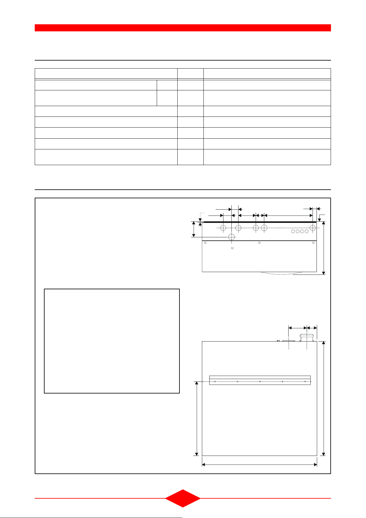
3 - DIMENSIONS
Fig. 1
102
19
55,5
45,5
117 56 323 ,5
cd
h
i
27
56
b
g
361
Legend:
a : Combustion products outlet
b : Gas inlet
c : Heating flow
d : Heating return
e : /
f : /
g : Condensate drain
h : Safety valve drain
i : DHW production system connection (option)
495
THI-05- 0
Bottom view
120 67,5
a
Rear view
760
- 7 -
765
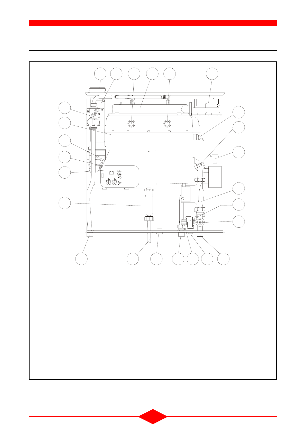
4 - LIST OF COMPONENTS
Fig. 2
TECHNICAL SPECIFICATIONS
104
13
3
13
11
THI-06-0
12
23
5
14
21
2
7
9
16
15
17
18
1
1) Gas inlet
2) Gas unit (solenoids and regulator) 230 V
3) Gas burner
4) Combustion products outlet
5) Flue gas sensor
6) Heating flow
7) Heating outlet and safety sensor
8) Heating return manifold
9) Boiler return sensor
10)Ignition transformer 230 V
11) Fan 230 V
12)Boiler shell
13) Sight-glass
14) Microprocessor control panel
24
15)3 speed pump 230 V
16) Air bleed
17)Pressure sensor
18) Filter and drain tap
19) Safety valve 3 bar
20) Safety valve outlet
21) Siphon trap
22)Condensate drain
23)Combustion check window
24)DHW production system connection (option)
6 8
19
2022
- 8 -
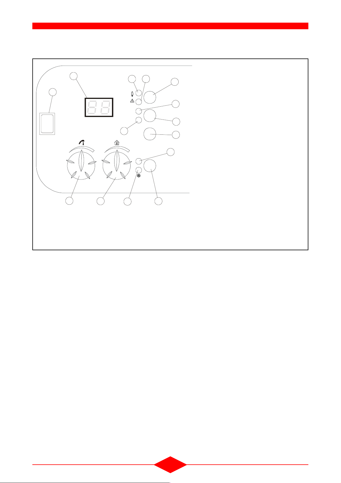
4.1 - Control panel
Fig. 3
13
1112
10
14
Reset
I
°C
bar
Info
8
O
3
* The function of the heating temperature (2) and DHW temperature (3)
potentiometers differs according the 3 examples below.
**The On/Off switch (after initial lighting) should be maintained in the "ON"
position in order to preserve all the automatic functions of the boiler (anti-freeze, anti-legionella functions, etc).
2
j
auto
Function
5
1
9
7
6
4
THI-01-0
TECHNICAL SPECIFICATIONS
1) The "Function" key gives access to 3 operating
modes by simply pressing the key:
auto mode: LED (4) on
winter mode: LED (5) on
summer mode: LED (4) and (5) off
2) Regulation of the heating temperature (setting
read on the display (13)) *
3) Regulation of the DHW temperature (setting
read on the display (13)) *
6) Maintenance key: reserved for servicemen or
maitenance (see overleaf)
7) "Info" key gives access to 5 types of information
on the display (13) by simply pressing the key:
Boiler outlet temperature: LED (9) on
Sensor temperature: LED (9) flashing
Boiler water pressure: LED (8) on
Operating phase: LEDs (8/9) off
Diagnostics: LEDs (8/9) off/
Display (13) flashing
10) Boiler reset button (After each reset, wait for
about 30 seconds before the restart = reset)
11) Alarm: Red LED on
12) Flame indicator: Green LED on
13) Digital display: Alternatively displays the setting
selected by the "Info" key and the current default
code
14) ON/OFF switch (depending on the models) **
THI Without room sensor or outside sensor
The heating (2) and hot water (3) temperatures setting are manually set on the boiler control panel.
- The FUNCTION key (1) gives access to 2 operating modes:
• Auto mode operation (4): no access
• Winter mode operation: LED (5) on
• Summer mode operation: LED (5) off
THI Without room sensor and with outside sensor
Possibility of correcting the heating temperature (2)
computed automatically using the outside tempera
ture and manual setting of the hot water temperature (3) on the boiler control panel. (The room
temperature setting can be changed by + or - 3°C
maximum according to the setting).
- The FUNCTION key (1) gives access to 3 opera-
ting modes:
• Auto mode function:
auto winter = Leds (4) and (5) on
auto summer = Led (4) on + Led (5) off
• Winter mode operation: LED (5) on
• Summer mode operation: LEDs (4) and (5) off
THI With room sensor and outside sensor
Fitting the QAA73 room sensor cancels the functions of the heating temperature setting (2) and hot
water setting (3) on the boiler control panel. All the
temperatures required, together with the heating
programmes, are set on the QAA 73 (refer to the
sensor instructions).
- 9 -
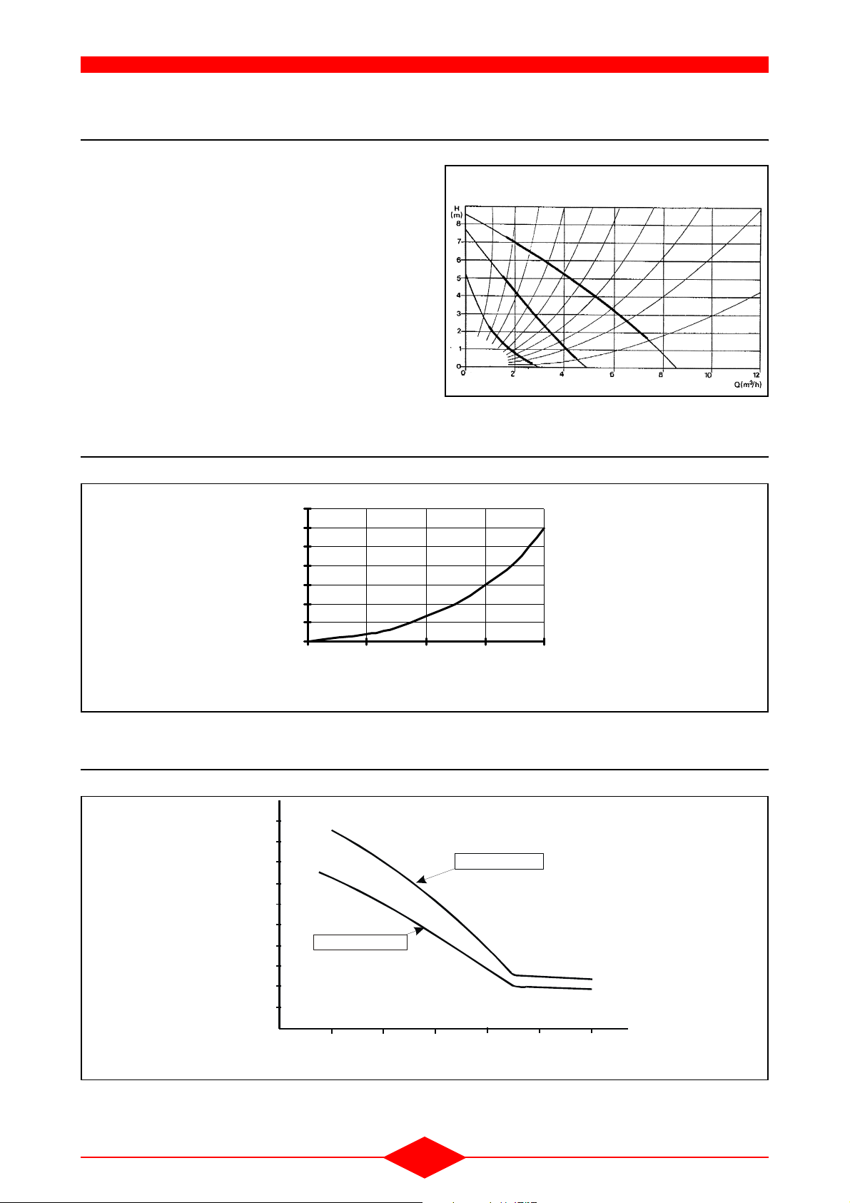
5 - CIRCULATING PUMP CHARACTERISTICS
TECHNICAL SPECIFICATIONS
The boiler’s integrated circulating pump is equipped
with a 3 speed motor (refer to section
1 - page 6).
Fig. 4
Electrical consumption of the heating circulating
pump can be optimised by adapting its speed to the
needs of the installation.
6 - PRESSURE DROP IN THE BOILER (HEATING CIRCUIT)
Fig. 5
7
6
5
4
3
2
1
Pressure drop (mWG)
0
0 500 1000 1500 2000
3
Flow rate (dm
/h)
UPS 25-80-180
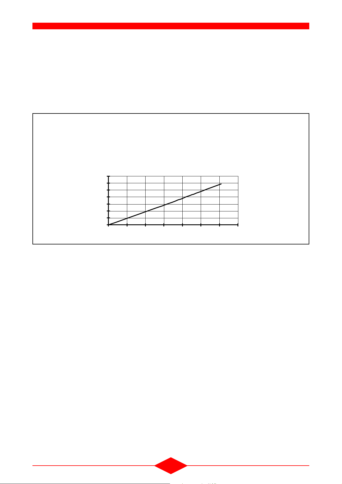
7 - THERMAL EFFICIENCY
Fig. 6
1,10
1,08
1,06
1,04
1,02
1,00
0,98
PCI efficiency
0,96
0,94
0,92
0,90
10
Maximum rate
20 30 40
Installation- empératurereturn t
- 10 -
Minimum rate
50
T50-03- 3
60 70

III - OPERATION
1 - GENERAL OPERATING PRINCIPLE
The THI boiler is a very high efficiency condensation
boiler owing to the burner and heat exchanger that
benefit from our longstanding experience.
The over-sized fin tube exchanger and its combustion chamber cooled by water in the upper section,
combines the functions of heat exchanger and con
denser.
Second generation digital control continuously optimizes the operating rate by using information sent to
the microprocessor by the sensors fitted on the boi
ler:
- boiler flow sensor,
- boiler return sensor,
- outside temperature sensor,
- flue gas flue gastemperature sensor,
- room sensor,
- pressure sensor,
- fan speed control (pneumatic air/gas control),
- communication bus with external regulators.
-
-
Each of the sensors is allocated to an algorithm that
optimizes the operation and generates information
or fault codes that can be read from the display of
the control panel or QAA73 room sensor.
- 12 -

2 - OPERATION OF THE LMU MANAGEMENT UNIT
2.1 - Normal operating conditions
OPERATION
To access the operating phases of the LMU (display
level A4), press the info key (7) three times. The dif
-
Fig. 7
ferent phases will then be displayed (13).
Note:
INFO-0
- The phase display will stop automatically after 8
minutes,
- Otherwise, press the info key 2 times more.
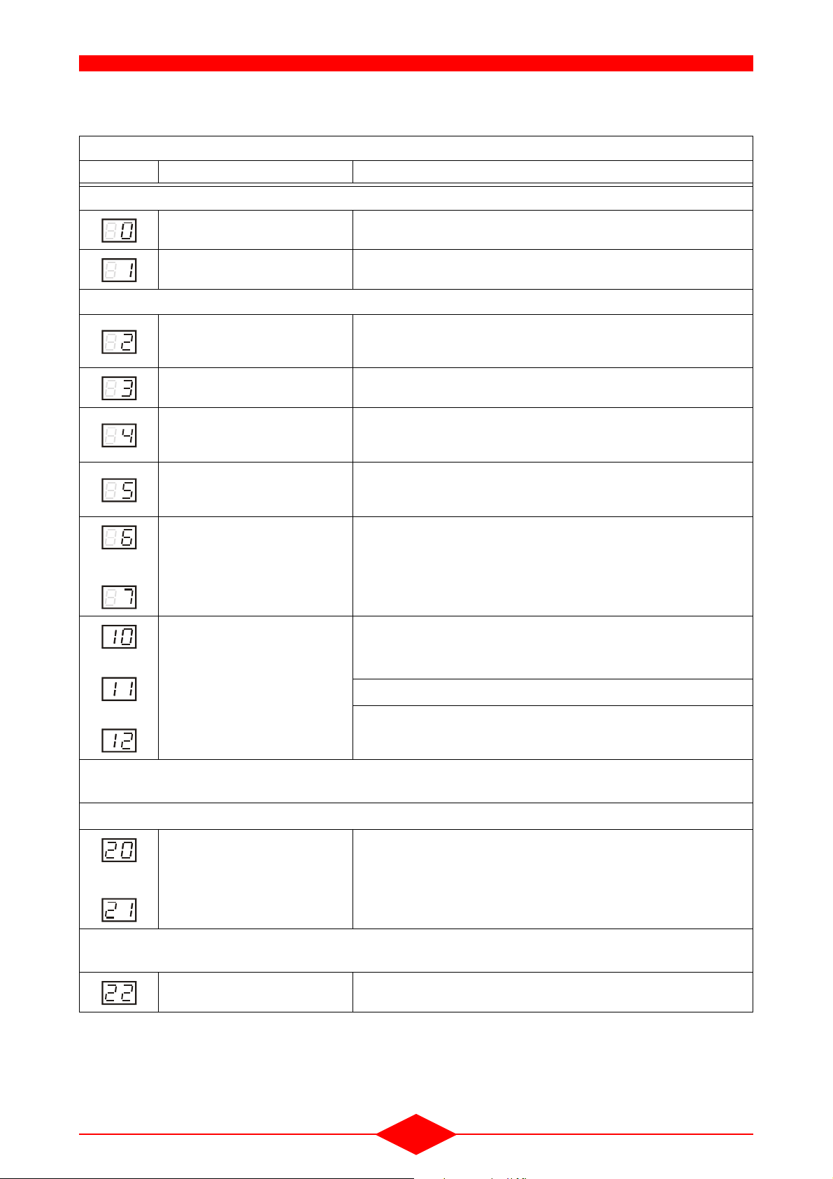
Programming order for normal operating conditions
Display Meaning Display Meaning
Stand-by (no heating request) Ignition - safety time
Start-up blocked Heating mode operation
Fan speed rise time Hot water mode operation
Pre-ventilation time Heating + DHW operation (disabled for
THI)
Waiting time Post-ventilation with last operation
command
Pre-ignition time Return to initial setting
Fault position (display of current fault
code)
°C
bar
Reset
Info
713
2.2 - Operating diagram
Fig. 8
HMI
display:
Phase
Head
demand
Flame
Ignition
BV
LP (2)
LP (3)
LP (4)
NoG_Max
N_Vor
-N_Vor_Delta
+N_VL_Delta
N_VL
+N_ZL_Delta
N_ZL
-N_ZL_Delta
N_TL
-N_TL_Delta
NoG_Null
THI-65-3
7494f01D/0801
Home return
TNB
PH_TNB
Logic on
Logic off
On deviation
transition to home run
TLO
PH_TLO PH_TNN
022 1 2 3 654
Standby
TNN
PH_
STANDBY
PH_
STARTVER
PH_
STANDBY
tv TBRE
THL1
PH_
THL1_1
PH_TV PH_TB RE PH _TW1 PH_TW2 PH_TVZ
Depend on
para meter
setting
TW1 TW2
Deviati on leads to lockout
On deviation transition to
specified or following phase
10 H
11 DHW
12 H+DHW
tsa
Operation
tvz
tsa1 tsa2
PH_
TSA1_1
PH_
THL2
Z Z
Z ZZ Z Z Z
Depend on
parameter
setting
PH_
TSA2_1 PH_TI
Z
PH_
THL2
Z
Z Z
THL2
THL2
ti
PH_
PH_
20 2 4 7 21 99
tn
PH_
MODULATION
PH_
THL2
PH_
THL2
PH_
THL2_1 PH_TN_1
Depend on
parameter
settin g
THL1 (TW1)
PH_
PH_TW1
THL1_2
Depend on
parameter
settin g
Permitted range
Prohibited range
-> Home run
Prohibited range
-> Lockout
tsa
tsa1 tsa2
PH_
TSA1_2
Z Z
PH_
THL2
Z
Depend on
parameter
setting
Z
THL2
PH_
PH_
TSA2_2
THL2_2 PH_TN_2
PH_
THL2
PH_
TSA1_2
Z
Z
Depend on
para meter
setting
Control signal
Ideal signal
Transition criterio n
Triggering forced prepurging
tn
PH_
STOER
Z
Z
Z
- 13 -
Explanation of the operating phases
Display Phase Description
Shut down
PH_STANDBY (unlimited) The boiler is on standby and waiting for a heating request.
OPERATION
PH_STARTVER Start-up is blocked. The corresponding diagnostic code is emitted (shunt
Start-up: heating request
PH_THL1_1 (THL1) Fan speed rise time:
PH_TV (tv) Pre-ventilation time
PH_TBRE + PH_TW1 Tapering time
PH_TVZ (tvz) Pre-ignition time:
PH_TSA1_1 + PH_TSA2_1 (tsa) Safety time
and
PH_TI + PH_MODULATION: Burner operation
and
X10-03).
- This time ends as soon as the fan motor speed reaches the program
for pre-ventilation
- This time ends as soon as the ignition load programmed for pre-ventilation is reached
- Appearance of the ignition arc prior to opening the gas valve, which occurs at the start of phase 6
- A flame signal should be present before the safety time has elapsed. If
this does not occur, another ignition attempt is made.
10: heating operation
11: domestic hot water operation
12: heating and domestic hot water operation (disabled for THI)
and
• PH_TI...............................:
• PH_MODULATION...........:
Flame stabilisation interval.
In this phase, the LMU (regulator) send its results.
Return to standby: The switch from the operating position to the Standby position is split into “shut-down”
and “return to initial setting”
Shut-down: This occurs when the heating request disappears
PH_THL2_1 + PH_TN1 Post-ventilation time
and
- The fan remains on during the post-ventilation time
Return to initial setting: Compulsory switch from the shut-down position to standby. This phase is also
used to bring the boiler to standby position after exceptional events such as a RESET.
PH_TNB + PH_TLO + PH_ TNN:
Return to initial setting
- 14 -
2.3 - Principle of air/gas servo-control system
The gas valve fitted on each boiler is controlled by
the air pressure supplied by the fan, thus guaran
teeing a correct air-gas ratio over the whole modulation range (constant CO2). This ratio remains
constant despite any pressure drop in the combus
tion products outlet or the air intake. The air-gas link
is pneumatic.
Fig. 9
Operating characteristics of the air/gas servo-system
P2: gaz pressure at valve regulator outlet
PL: servo-system air pressure
P2 mbar GN
7
6
5
4
3
2
1
0
01234567PL mbar
OPERATION
2.4 - Air pressure variation procedure
Linear pressure modulation is carried out by a 230 V
variable-speed fan controlled by the LMU which cal
culates the speed needed at any given time to produce the required pressure.
2.5 - Emission of pollutants
This air/gas control combined with high efficiency
pre-mixing burner enables CO and nitrogen oxide
(NOx) emissions to be obtained that lie within the
values laid down by the most demanding of quality
standards.
-
- 15 -

3 - FUNCTIONS
OPERATION
3.1 - Anti-freeze function
- Boiler anti-freeze protection: When the boiler
temperature is below 5°C, the burner and the
heating circuit pump are switched on. When the
temperature increases and exceeds 15°C, the
burner stops and the pump continues to circulate
for 10 minutes.
- Anti-freeze protection for the installation: This
function uses the real outside temperature. It
adopts a different behaviour depending on the
temperature. If no measured outside temperature
is available, the function is blocked.
Different reactions can occur depending on the
outdoor temperature measured:
• If the outdoor temperature is less than or equal
to -5°C, the pumps operate continuously,
• If the temperature lies between -4 and 1.5°C,
the pumps operate for 10 minutes every 6
hours.
• If the outdoor temperature is over 1.5°C, the
pumps shut-down (no heating request).
Any domestic hot water request is given priority.
- Building anti-freeze protection:
The anti-freeze function of the building is a control
function (available with the QAA73 room sensor)
used to maintain the room temperature at a mini
mum value, thus preventing the risk of freezing in
the building.
3.2 - Anti-legionnella function
To provide a substantial degree of protection
against the development of pathogenic bacteria in
the domestic hot water tank during prolonged shutdowns, the domestic hot water must be heated once
a week to a temperature above 60°C.
-
3.3 - Pump run-on after the end of heating
When the heating mode ends, the heating circuit
pump remains on for a certain period (depending on
the settings used : QAA
In hot water storage systems, when domestic hot
water heating ends, the heating circuit pump re
mains on until the boiler temperature drops below
70°C. During this pump run-on period, the selector
valve remains in the “domestic hot water feed” posi
tion.
3.4 - Pump kick or selector valve kick
If the heating circuit pump has not operated or if the
selector valve has not been activated for more than
about 24 hours, these elements are activated during
operating stops for approximately 5 seconds.
3.5 - Boiler overheat protection
The boiler flow sensor in combination with the heating return sensor provide the overheat safety function.
There are two safety levels:
- if the first temperature value is exceeded, this is
signalled by a fault code on the display screen,
• THI 10-50 : 90°C
- if the second temperature value is exceeded
(100°C), it is signalled by an alarm code on the
display. The boiler switches to safety mode. The
boiler must be reset to be restarted.
If the temperature is exceeded, the heat present
must be evacuated through the fan and circulation
pump.
The two elements (fan and circulation pump) remain
on until the boiler shell temperature drops.
73 setting : 544).
-
-
The anti-legionnella function is used for this purpose. It heats the hot water storage tank once a week,
on Monday, after the first load, to a 65°C “anti-le
gionnella” temperature.
-
- 16 -
In the control algorithm, supervision of the temperature difference DT between the flow and return results in the shutdown of the burner if DT is above
56°C.
OPERATION
3.6 - Monitoring of flue gas temperature
The monitoring of flue gas temperature is not
classed as a function related to safety, but is a prio
-
rity factor in the control of the boiler.
- The boiler operates at minimum power if the flue
gas temperature exceeds 85°C,
- The boiler is on "Stand-by" if the flue gas temperature reaches 88°C.
The boiler can only be restarted automatically after
15 minutes if there is no longer a fault.
3.7 - Boiler return temperature control
The information from the return sensor is used in the
event of a very low flow (large
DT) (reduction in bur-
ner power or shut-down of the burner).
It is also enabled for cascade connection.
3.8 - Monitoring of hydraulic pressure
This is a priority function with respect to the control
of the boiler.
- the power of the boiler is limited if the pressure is
above 4 bar,
- the boiler reduces power to 20% if the pressure in
between 0.2 and 0.4 bars (fault code is dis
-
played),
- the boiler sets of an alarm and the pump stops if
the pressure is lower than 0.2 bars (alarm code is
displayed).
The boiler must be reset to clear the fault position if
the minimum value has been exceeded.
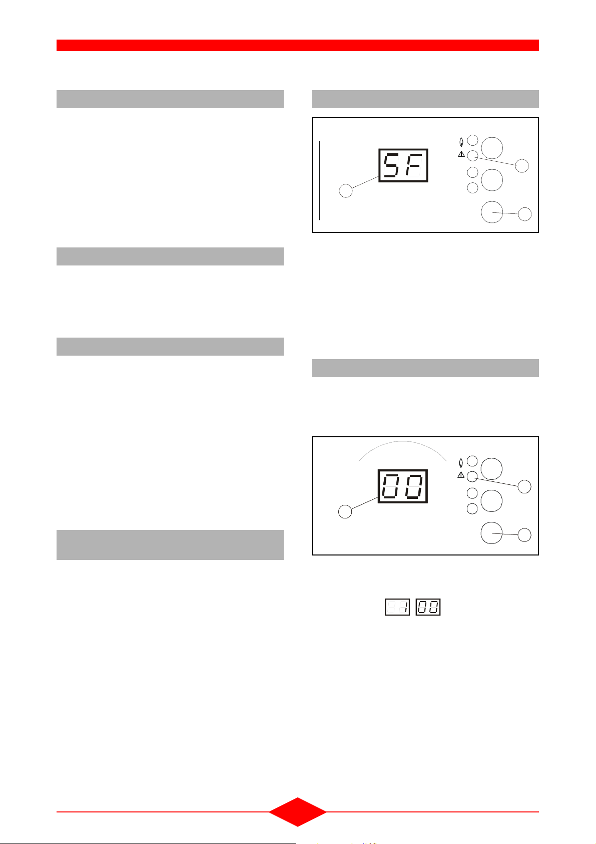
3.10 - Cleaning function
Fig. 10
Reset
11
°C
Info
13
RAMO-SF
bar
j
6
To enable this function, press the clean key (6) until
the red LED (11) lights up then release it. The LED
(11) then starts flashing once per period. The signal
ling coded “SF” is displayed on the screen (13).
Heating takes place at maximum calorific power until arriving at the maximum temperature TKSmax.
To disable the cleaning function, press on the clean
key (6) for 3 seconds then release it.
3.11 - Regulator shutdown function
The regulator shut-down function enables the fan
motor speed to be set manually via a domestic hot
water temperature potentiometer (3), and therefore
the heat output of the boiler.
Fig. 11
Reset
Reset
11
11
13
13
°C
°C
bar
bar
Info
Info
-
3.9 - Anti-short burner cycle protection
function
To prevent the boiler from cutting out suddenly, the
power failure differential is adjusted according to the
real temperature curve of the boiler.
j
j
RAMO-AR
RAMO-AR
- Press the clean key (6) for longer than 8 seconds,
• The red LED (11) flashes twice per period.
• The codes appear on the display
(13) and flash twice. This code corresponds to
the percentage of the boiler heating rate.
The safety function and the “all or nothing” regulator
are operating.
To disable the regulator shutdown function, press
the clean key (6) for 3 seconds then release it.
- 17 -
6
6

OPERATION
3.12 - LMU programmable key
The following functions can be allocated to the programmable key via the setting
KonfigEingang (QAA 73 setting : 614):
- 0: The programmable key function is not used.
- 1: Default, modem function enabled, if the contact
(X10-04) is closed; disabled if the contact is
open.
- 2: Modem function disabled, if the contact (X10-
04) is open; enabled if the contact is closed.
- 3: Hot air curtain function enabled, if the contact
(X10-04) is closed.
Hot air curtain function (swimming pool):
This function enables the boiler setting to be raised
to its maximum value.
It can be enabled in summer and winter modes.
- Modulation of the burner output is maintained.
- Domestic hot water priority is maintained.
- This function is enabled when the contact is
closed.
Modem function:
The modem function allows the boiler to be placed
on "standby" or to be switched off via the telephone.
All protection functions (e.g. anti-freeze function,
pump kick) remain active.
3.13 - Automatic summer/winter switching
(only activated with outside sensor)
The automatic summer/winter switching function
enables summer mode to be switched to winter
mode (and vice versa) throughout the year without
the need for any intervention.
The heating is shut down (when switching from winter mode to summer mode) when the average outside temperature measured over the preceding 24
hours is over the +1°C setting, namely 20°C.
The heating is also started up again (when switching
from summer mode to winter mode) automatically
when the average outside temperature measured
over the preceding 24 hours is below the -1°C set
ting, namely 18°C.
-Note:
The switchover setting is set to 19°C and can only
be changed by using the QAA 73 room sensor.
The automatic mode must obviously be activated
on the boiler as well as on the QAA 73 room sen
sor for the automatic summer/winter switching to
be available.
This function is activated by default in the QAA 73
basic configuration.
-
-
On the other hand, when this function is activated,
some of the other functions are not ensured:
- The antifreeze function of the installation is not
guaranteed.
- The anti-legionella function of the unit is no longer
used.
- 18 -
4 - DIFFERENT VERSIONS OF THE THI
,
,
,
OPERATION
The standard configuration is for the
connection of:
!
- one radiator circuit (CC1),
- one under-floor heating circuit
(CC2) via the 2
nd
circuit clip-in kit.
Fig. 12
auto
Function
23
4
THI-66-0
15
4.1 - THI basic model (without outside
sensor, without room sensor)
The heating and domestic hot water flow temperatures are set manually with the respective potentiometers (2 and 3) on the boiler control panel.
The regulator (LMU management unit) thus sets the
heating rate required to provide the heating and hot
water settings specified by the user.
The “Function” key (1) switches between the summer (hot water only) and winter (heating and hot water) modes. (The auto function is not accessible in
this case).
Please refer to section 4.1 - page 9 - Chapter II TECHNICAL SPECIFICATIONS.
Note: The installation of under-floor heating is not
possible in this configuration.
4.2 - THI with outside sensor only
4.2.1 - Principle
The domestic hot water temperature is set manually
using the potentiometer (3) on the boiler control pa
nel
Refer to section 4.1 - page 9 - Chapter II - TECHNICAL SPECIFICATIONS.
Note:
- An under-floor heating system can be connected
by following the instructions in section
4.2.3 -
page 19.
4.2.2 - Modification of the room temperature
The room temperature setting is pre-set to 20°C on
the LMU management unit, it can be modified if re
-
quired:
- Set the heating temperature potentiometer (2) to
the required value,
- The display indicates the correction made by +/3°C with respect to the 20°C value,
The correction is recognised by the LMU by leaving the potentiometer on the required position.
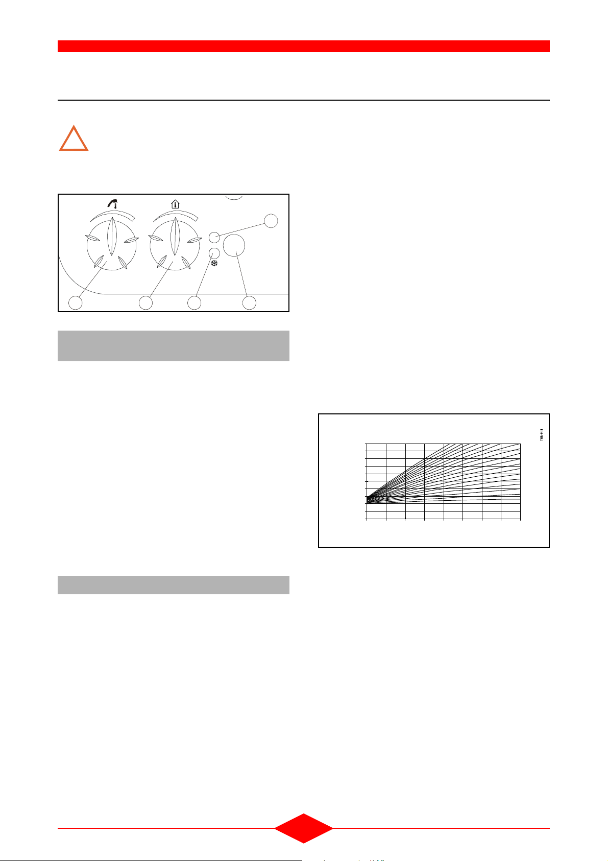
4.2.3 - Modification of the heating curve slope
The heating curve slope depends on the characteristics of the building and the size of the heating installation.
Fig. 13
100
90
80
70
60
50
40
30
Boiler setpoint
temperature (°C)
20
10
0
20 15 10 5 0 -5 -10 -15 -20
Outside temperature (°C)
2,4
2
1,8
1,6
1
4
2
1
1
Slope
0,8
0,6
4
0
0,2
The slope of the heating curve is pre-set in the factory to the value 15 for a radiator system and theoretically gives an room temperature of 20°C for a
standard installation.
Note: The maximum permitted flow temperature is
limited by TKSmax (line 504, via the QAA73
-
room sensor)
The heating flow temperature is calculated automatically by the regulator (LMU management unit), and
determined according to the outside temperature
and the slope of the heating curve. The room tem
perature can be modified by only + or - 3°C using the
heating temperature potentiometer (2).
The “Function” key (1) switches between the summer (hot water only) and winter (heating and hot water) modes.
- 19 -

OPERATION
The characteristics of the living area (heating surface, insulation) may require the pre-set values on the
LMU to be adjusted.
- For a radiator heating system:
• Reset the room temperature by +/-3°C (section
4.2.2 - page 19) then if this correction is not
sufficient,
- For an under-floor heating system:
• Reset the value of the heating curve slope of
15 (factory setting) to 8 (section
20) and according to the installation requirements,
• Modify the room temperature by +/-3°C (section 4.2.2 - page 19).
• Modify the heating curve slope (section 4.2.3.1
- page 20).
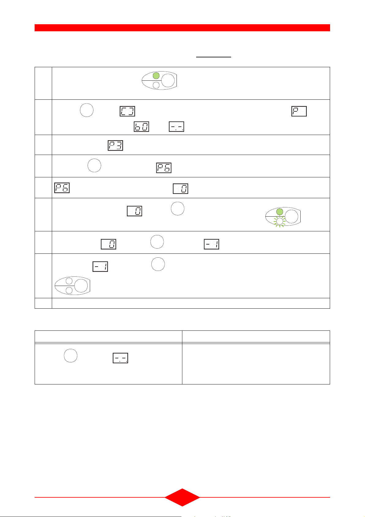
4.2.3.1 - Procedure for modifying the parameters of the heating curve slope
Initial display: Green LED “°C” is on
1
The display shows the heating flow temperature.
Press the key until is displayed then release it and press for the same period until is
Info
2
displayed (the display indicates then : intermediate positions).
3
After a few moments, is displayed.
°C
bar
Info
INFO-22
4.2.3.1 - page
4
Press on the key twice until is displayed on the screen.
5
6
7
setting of the slope permutes with the default value of the slope.
Only when the display shows press the key until the “bar” LED flashes:
Increase the value by pressing until the value is displayed.
Store the value by pressing the key for a certain time until the LEDS “°C” and “bar”
Info
Info
Info
Info
8
°C
bar
Info
extinguish
INFO-8
9 Return to the initial display
°C
bar
Info
INFO-15c
- 20 -
4.2.3.2 - Procedure for modifying the parameters of the parallel shift of the heating curve
OPERATION
Initial display: Green LED “°C” is on
1
°C
bar
Info
INFO-22
The display shows the heating flow temperature.
Press the key until is displayed then release it and press for the same period until is
Info
2
displayed (the display indicates then : intermediary positions)
3
After a few moments, is displayed.
4
Press on the key three times until is displayed on the screen.
5
6
7
setting of the parallel shift permutes with the default value of the shift.
Only when the display shows press the key until the “bar” LED flashes:
Increase the value by pressing until the value is displayed.
Info
Info
°C
bar
Info
Info
INFO-15c
Store the value by pressing the key for a certain time until the LEDS “°C” and “bar”
Info
8
°C
bar
Info
extinguish
INFO-8
9 Return to the initial display
4.2.3.3 - Return to the initial display
Procedure Observation
Press the key until the display appears
then release the key.
Info
This enables you to return to the initial position (i.e. the
display shows the heating flow temperature) when the
procedures
4.2.3.1 - page 20 and 4.2.3.2 - page 21 are
being applied or during any other actions on the boiler
control panel.
- 21 -

OPERATION
4.3 - THI with outside and room sensors
Fig. 14
auto
Function
23
4
THI-66-0
15
Installing the QAA73 room sensor on the boiler cancels the functions of the setting potentiometers of
the heating (1) and domestic hot water (2) tempera
tures on the boiler control panel. All the temperatures, the operating settings and the heating
programmes are set on the QAA
73 (please refer to
the instructions supplies with the sensor).
Note:
- For heating by radiators or by under-floor heating,
refer to section
4.2.3 - page 19.
4.3.3 - Auto-adapt function
This function automatically corrects the heating curve by measuring the real room temperature.
The auto-adapt function is deactivated in the basic
configuration. It can be activated via line 77 by using
the +/- keys.
When the auto-adapt function is activated, the room temperature compensa-
!
tion function must also be activated,
section
4.3.2 - page 22.
4.3.1 - Automatic summer/winter switching
Refer to section 3.13 - page 18.
4.3.2 - Room temperature compensation
function
This function corrects the boiler flow temperature
according to the real room temperature measured
by the QAA 73 room sensor.
The QAA 73 can be deactivated or configured differently according to the wishes of the customer (refer
to heating engineer setting line 75).
Note:
- The “room temperature compensation” function is
activated by default on the CC1 heating circuit standard configuration of the sensor.
- The function is activated if the room sensor is pla-
ced in a room whose temperature is typical of the
accommodation. This room must not be fitted
with temperature control radiators. The room sen
sor must be fitted away from sources of heat or
cold.
When the room temperature compensation is inactive, the QAA 73 room sensor becomes a remote
control device acting on the heating curve for the
day-night temperature drops.
-
- 22 -

1 - GENERAL
IV - INSTALLATION
Installing a wall-mounted gas boiler presents no particular difficulty.
The installation of the boiler must be carried out by
a competent person in accordance with the relevant
requirements of the Gas Safety (Installation and
Use) Regulations, Building Regulations, Model Wa
ter Byelaws and the Building Standards (Scotland)
Regulations. It must also comply with the current
I.E.E. Wiring Regulations and the relevant recom
mendations of the following British Standard Codes.
Regulations and the relevant recommendations of
the following British Standard Codes of Practice.
CR331.3 Low pressure installation pipes.
BS.5449.1 Forced circulation hot water systems.
BS.5546 Installation of gas hot water supplies
for domestic purposes.
BS.5440.1 Flues (for gas appliances of rated input
not exceeding 60 kW).
BS.5440.2 Air supply (for gas appliances of rated
input not exceeding 60 kW).
BS.6798 Boilers of rated input not exceeding
60
kW.
Note:
- The boiler is only suitable for installation in a sea-
led system and must not be used with an open
vented system.
LOCATION OF BOILER
-
-
An existing cupboard or compartment may be used
provided it is modified for the purpose. Details of es
sentiel features of cupboard/compartment design,
including airing cupboard installations, are given in
BS.6798.
In siting the boiler, the following limitations MUST be
observed:
1) The position selected for installation MUST allow adequate space for servicing in front of the boiler and for
air circulation around the boiler.
2) This position MUST also permit the provision of a satisfactory balanced flue termination.
Note:
- If the boiler is to be fitted in a timber framed buil-
ding, it should be Jitted in accordance with the
British Gas publication "Guide for Gas Installa
tions in Timber Frame Housing". Reference DM2.
If in doubt, advice must be soughtfrom the Local
Gas Region of British Gas.
When siting the boiler, provision must be made for
the disposal of the condensate, see Section 4 -Con
densate drain.
The pressure relief valve connection should be routed to an external, visible point where the discharge
of steam or water cannot create a hazard to persons
or property. BS.5449: 1 refers.
GAS SUPPLY
Installation pipes should be fitted in accordance with
CP.331.3.
-
-
-
The boiler can be installed on the inner face of an
external wall - and some internal walls - providing
they are flat, vertical and capable of adequately sup
porting the weight of the boiler and any ancillary
equipment.
The boiler may be installed in any room or internal
space, although particular attention is drawn to the
requirements of the current I.E.E. Wiring Regula
tions and, in Scotland, the electrical provisions of
the Building Regulations applicable in Scotland with
respect to the installation of the boiler in a room or
internal space containing a bath or shower. Where
installation is in a room containing a bath or shower,
any electrical switch or boiler control utilising mains
electricity should be situated so that it cannot be tou
ched by a person using the bath or shower.
Where installation will be in an unusual location,
special procedures may be necessary and BS.6798
gives detailed guidance on this subject.
A compartment used to enclose the boiler MUST be
designed and constructed specially for this purpose.
-
-
-
The complete installation must be tested for soundness and purged in accordance with CR331.3.
FLUEING
Detailed recommendations for flueing are given in
BS.5440.1. The following notes are intended for ge
neral guidance.
AIR SUPPLY
a) - For room-sealed systems
Detailed recommendations for air supply are given
in BS.5440.2. The following notes are intended for
general guidance.
Where the boiler is to be installed in a room or internal space, the boiler does not require the room or internal space containing it to have a permanent air
vent.
Where the boiler is to be installed in a cupboard or
compartment, permanent high and low level air
vents are required for cooling purposes in the cup
board or compartment. Both vents must communi-
-
-
- 23 -

INSTALLATION
cate with the same wall to outside air.
The minimum effective area of the permanent air
vents required in the cupboard or compartment are
given in Table 3.
Table 3 AIR VENT AREAS
Position of
air vents
Air from room or
internal space
Air direct
from outside
High level 500 cm² 250 cm²
77.5 in² 39 in²
Low level
500 cm² 250 cm²
77.5 in² 39 in²
b) - For natural draught system:
Detailed requirements are given in BS 5440.2
2 - VENTILATION
WATER CIRCULATION SYSTEM
A suitable expansion vessel must be fitted to the
system external to the boiler and must be sized
to accommodate the expansion of the total water
content of the system. BS7074 and "British Gas
Specifications for Domestic Wet Central Heating
Systems' Part 3 gives guidance in this subject.
The central heating system should be in accordance
with the relevant recommendations given in
BS.6798 and, in addition, for small bore and micro
bore systems - BS.5449.1. The domestic hot water
system, if applicable, should be in accordance with
the relevant recommendations of BS.5546.
Copper tubing, to BS. 287 1. 1, is recommended for
water carrying pipework.
ELECTRICAL SUPPLY
- Wiring external to the boiler must be in accordan-
ce with the I.E.E. Wiring Regulations and any local regulations.
2.1 - THI models with conventional flue
connection
- All fuel burning devices consume a quantity of air
that is proportional to their power. Efficient venti
lation of the installation’s premises is therefore
necessary (according to installation standards).
• High ventilation, with a free section of at least
100 cm², should be placed at least 1.80 m abo
ve the ground, as well as an air inlet, in the
lower part, of a cross-section of 100 cm².
- To avoid any form of corrosion, the combustion
air must be free of any harmful agents. They are
thought to encourage the corrosion of halogena
ted hydrocarbons, containing combinations of
chlorine or fluorine, which can be found in sol
vents, paints, glues, gas propellants and domestic cleaning products, etc.
2.2 - THI models with balanced flue connection
When the THI boiler is installed with the horizontal
-
or vertical balanced flue kits that are supplied as op
tions, the combustion circuit is sealed in relation to
the installation premises.
These sealed units can be installed on premises
-
that either have or do not have windows or air inlets.
However, all measures must be taken to ensure that
the temperature of the installation room does not ex
ceed 45°C (ventilation).
-
-
- 24 -

3 - COMBUSTION PRODUCT FLUEING
INSTALLATION
The combustion product outlet systems described in this manual are sys-
!
tems normally used on the European
market. However, some of them cannot
be used in all the countries of the EEC.
The installer or client must ensure that
the flue system chosen complies with
local installation regulations.
3.1 - Conventional flue outlets (B23 model)
- The THI boiler operates by condensation, which
involves the use of a sealed drain outlet. The
combustion products are saturated with water va
pour and continue to condense onto the walls of
Fig. 15
the lining. The condensates must therefore be
collected at the base of the conduit and directed
to the drain. The condensates are acids (PH4), so
the use of a stainless steel conduit is recommen
ded.
- Systematically check that the condition and the
cross-sectional area of the flue are correctly
adopted to open flued combustion product ex
traction. If they are defective, carry out repairs or
tubing in accordance with the installation stan
dard.
- If the boiler is installed in premises that have mechanical air extraction, check regularly that this
does not cause negative pressure.
- The conventional flue connection must be installed by retaining an upwards slope towards the
-
flue (2% minimum). Use a rigid flue that has a
smaller diameter than that of the boiler
.
-
-
-
Ventilation
Boiler connection
Sealed flue
Æ
139
Alu réduction
139/80
Æ
Boiler
PVC 25
Æ
Tubing ventilation
Sealed tubing
Trap, accessible for
inspection minimum seal
depth 50 mm (for draining
condensates from tubing)
Æ
PVC 32
Traps
(these 2 drains may
be shared)
050-14-3
- 25 -

3.2 - Balanced flue outlet
INSTALLATION
3.2.1 - Balanced flue system installation requirements:
The recommended clearance distances according to the installation standards are:
- A = 0.30 m: minimum clearance distance of the
combustion production extraction outlet axis to
any opening,
-B = 0.30 m:
minimum distance from the axis of the combustion production extraction outlet to any other ventilation air inlet,
-C = 2.00 m:
combustion product extraction outlet and air inlet
of sealed circuit units with openings at less than
2.00m from the ground must be efficiently tam
per-proof so as to prevent any intervention that
could affect correct functioning.
Fig. 16
B
Combustion product extraction outlets that open
out directly onto an outside route (public or priva
te road) less than 1.80m from the ground, except
for condensation installations, must have a fixed
defector that redirects discharged gas more or
less parallel to the wall.
Recommended distances:
-D = 0.30 m:
centre distance from the combustion product extraction outlet to the ground, from a roof overhanging or above a balcony,
- E = 0.60 m:
distance of a combustion product extraction outlet from a hedge or plant,
-
- F = 0.15 m:
space between the combustion product extraction outlet and a gutter or drainpipe.
A
D
F
B
A
A
C
D
B
E
B
AM5-10- 0
- 26 -

INSTALLATION
3.2.2 - General
Check that the air inlet and combustion product extraction outlet tube and bend joints are properly sealed after mounting.
Air intake by the burner and extraction of combustion product is carried outside the premises by using
concentric tubes.
Power is automatically reduced by means of the air/
gas servo-control system. No systematic adjust
ment is required when commissioning the installation. Only the usual CO and CO2 checks should be
carried out (§
3 - page 52 - chapter VII - GAS CONVERSION ). The maximum DP of 100 Pa is obtained with a vertical balanced flue DN 80/125 length
8 metres with two 45° elbows or with a horizontal ba
lanced flue length 4 meters.
Fig. 17
POW ER VARIATI ON DEPENDING ON FLUE AND AIR
47,5
47
46,5
46
45,5
45
Power Kw
44,5
44
0 20406080100120
INLET PRESSURE DROP
P Pascals
D
3.2.3 - Drainage by horizontal balanced flue
(C
)
13
To make assembly easier, apply liquid
soap over 5 cm of the section of the tube
!
to be fitted.
3.2.3.1 - 1 m horizontal balanced flue kit
(option)
See kit assembly guide
Fig. 18
-
050-13- 0
-
Reference
V00.23774 1000
Length
mm
3.2.3.2 - 2 m polypropylene/PVC concentric
flue extensions kit (option)
Fig. 19
- Standard balanced flue length: L = 1 m
- Maximum linear length of horizontal flue:
Lmax = 4 m
Recommendations
Horizontal balanced flue installation is
possible when the wall next to the boiler
!
leads to a well-ventilated area on the out
side.
Do not place the flue terminal at the front
of the building or in an access area (pos
sible obstruction).
The horizontal balanced flue can be fitted
to the right or lefthand side or directly to
the rear of the boiler and can cross a
wall-thickness of 1 metre maximum.
Two balanced flue terminals from two separate boilers, positioned side by side,
must be separated by a minimum distan
ce of 0.3 metres.
When installing the horizontal balanced
flue, use a 2% upward grade towards the
outside for the combustion product tube.
525-11-0
Reference
V00.24245 2000 80 125
-
3.2.3.3 - Polypropylene/PVC concentric bends
Length
mm
Æ int.
mm
Æ ext.
mm
kit (option)
-
-
Fig. 20
Reference Bend type
V00.24246 90° 80 125
Æ int.
mm
Note:
525-25-0
Æ ext.
mm
- Each 90° bend added reduces the total authorised length by 1 m
- 27 -

3.2.3.4 - Installation examples
Please refer to the guide when installing the kit.
Note:
- For lengths greater than 1 m (standard horizontal
flue kit) use the extensions and bends supplied
as an option.
Lmax £ 4 m
3.2.3.4.1 - Straight horizontal balanced flue
INSTALLATION
Fig. 23
Fig. 21
Lmax
050-26- 0
Top v iew
- Rear extraction -
Accessory:
- 1 horizontal balanced flue kit - l = 1 m.
Fig. 22
70
70
Lmax
050-30- 0
70
Top view
- Right-hand extraction -
Accessory:
- 1 horizontal balanced flue kit - l = 1 m.
3.2.3.4.2 - Flue with bend:
Fig. 24
050-27- 0
L1
Lmax
Top view
- Evacuation vers la gauche -
Accessory:
- 1 horizontal balanced flue kit - l = 1 m.
L2
70
Accessories:
- 1 horizontal balanced flue kit - l = 1 m.
- 1 concentric extension kit Ø 80/125 - l = 2 m,
- 1 x 90° concentric bend kit Ø 80/125.
050-29- 0
Lmax = L1 +1 m + L2 £ 4 m
Note :
- Each 90° bend added reduces the total permitted
length by 1m.
- 28 -

INSTALLATION
3.2.4 - Extraction by vertical balanced flue
(C
)
33
Besides the previously mentioned installation regulations pertaining to flues, the vertical flue terminal
must allow a minimum distance of 30 cm between
the roof level (sloping or flat) and the air intake zone.
The proximity of two terminals is also regulated: it is
recommended that two adjoining terminals should
be placed in the same horizontal plane. If this can
not be applied, the axis of the lower terminal must
be at a distance of at least 0.40 m from the closest
point of the air intake hole of the highest terminal.
Maximum length of vertical flue = 8 m
Fig. 25
30 cm
mini
40 cm
mini
3.2.4.1 - Polypropylene/PVC concentric
vertical terminal (option)
For sloping roofs.
Fig. 26
-
FCX-20-0
Reference Colour
N40.28393 Tile 1080 80 125
N40.28394 Black 1080 80 125
(*) Useful length under sleeve tile - l = 0.43 m
Length
(*) mm
Æ int.mmÆ ext.
mm
3.2.4.2 - Sleeve tile with adaptive coupling
(option)
Fig. 27
Recommendations
Horizontal parts must be avoided to
prevent any risk of condensate reten-
!
tion.
It is recommended to use 45° bends rather than 90° bends.
Use fastening collars for the vertical
parts.
Position the terminal at least 1 metre
from a vertical wall (end walls).
Apply liquid soap to approximately 5
cm of the part of the tube to be fitted to
make assembly easier.
FCX-19-0
AM5-22-0
Reference Slope
N40.12165 25 ° - 45 ° Tile* Tile
N40.12166 35 ° - 55 ° Tile* Tile
N40.12167 35 ° - 55 °
Type o f
covering
Slate -
Shingle
Colour
Black
*Suitable for all types of tiles, for flat tiles < 8 mm
use the Slate model
If accessories of any other brand are used, our guarantee of watertightness will be automatically void
3.2.4.3 - Polypropylene/PVC concentric
extensions (option)
Joint fitting.
Fig. 28
AM5-23-0
Reference
Length
mm
Æ int.
mm
Æ ext.
mm
N40.28397 500 80 125
N40.28398 1000 80 125
(*) Useful length after assembly - l = 0.45 m or 0.95 m
- 29 -

INSTALLATION
3.2.4.4 - Polypropylene/PVC concentric
bends (option)
Joint fitting.
Fig. 29
AM5-24-0
45° bend
Reference Type of bend
N40.28395 45° 80 125
N40.28396 90° 80 125
90° bend
Æ int.
mm
Æ ext.
mm
Each 45° bend added reduces the total permitted
length by 0.5m.
Each 90° bend added reduces the total permitted
length by 1m.
3.2.4.5 - Polypropylene roof plate (option)
Fig. 30
3.2.4.7 - Adapting collar for the vertical balanced flue
See assembly instructions for the part.
Fig. 32
THI100-0
Reference V00.24253
AM5-27-0
Reference Colour
A90.12172 noir
3.2.4.6 - Fastening collar (option)
Fig. 31
AM5-26-0
Reference Quantity
B00.29727 3 125
Æ
mm
These collars are essential to fix the vertically positioned extensions so that the boiler outlet does not
bear the weight of the conduits.
- 30 -

INSTALLATION
3.2.4.8 - Installation examples
3.2.4.8.1 - Straight configuration
Fig. 33
L
1
3.2.4.8.2 - Configuration with bends
Fig. 34
2
L
L3
L1
THI101-0
Accessories:
- Vertical balanced flue adapting collars,
- Concentric extensions Ø 80/125,
- 1 concentric vertical terminal Ø 80/125,
- 1 vertical terminal fastening collar (delivered with
vertical terminal),
- 1 sleeve tile with adaptive coupling depending on
the type of roofing and roof slope,
- 1 roof plate,
- 3 fastening collars Ø 125,
Lmax = L1 £ 8 m
THI102-0
Accessories:
- Vertical balanced flue adapting collars,
- 3 concentric extensions Ø 80/125,
- 2 x 45° concentric bends Ø 80/125
- 1 concentric vertical terminal Ø 80/125,
- 1 vertical terminal fastening collar (delivered with
vertical terminal),
- 1 sleeve tile with adaptive coupling depending on
the type of roofing and roof slope,
- 1 roof plate,
- 3 fastening collars Ø 125,
Lmax = L1 + 0,5 m + L2 + 0,5 m + L3 £ 8 m
Note:
- Each 45° bend added reduces the total permitted
length by 0.5m.
- 31 -

4 - SUPPORT BRACKET
Fig. 35
INSTALLATION
H
E
THI 10-50 C 150 82,5 495 265 10 10 - 79 56
Top view
B A A
THI-94-0
Modèles A B C D Emini Fmini G H I
F
7
Rear view
I
E
Æ
A B
A
Top view
D
C
F
- 32 -

5 - HYDRAULIC CONNECTION
5.1 - Recommendations
When the boiler is assembled on an old
installation, make sure that the installa-
!
tion is rinsed with fresh water, so as to
clear any sediment stagnating in areas
where the flow is slow.
To prevent circulation noises in an installation featuring temperature controls,
the following is recommended:
- Do not fit all the radiators with temperature controls,
- Fit a differential valve,
In accordance with the decree of the Ministry of Health for the protection of the
drinking water supply, the filling system
must be fitted with a disconnecter of type
CB (non-controllable pressure zone).
Never position the isolation valve
between the safety control and the
hot water tank (THI 10-50 C + DHW pro
duction system), never between the boiler shell and the expansion vessel.
5.2 - Accessories to connect, install or
adjust
- Bleed:
The bleed of the circulating pump features a flexible tube that can be connected to the outlet (condensate extraction funnel).
- Safety control (for hot water production models):
• The safety control must be installed at a
low point (0.25 m from the floor) in order to
enable the extraction of the domestic hot water
tank by siphoning. Otherwise, use a weld with
a low point drain tap.
• It is normal for the d.h.w. safety control to
leak a little water during the pre-heating of the
hot water tank. If the cold water pressure ex
ceeds 4 bars, the installation of a pressure-reducing valve on the cold water inlet is advised.
INSTALLATION
- Isolating valve:
It is recommended to place isolation valves on
the installation’s flow-returns in order to allow
possible servicing on the boiler without having to
drain the installation.
- Safety valve:
This must be connected to the used water drain
via a siphon funnel.
- Condensate outlet:
The condensate outlet must be connected to an
accessible siphon.
- Header
A header must imperatively equipped the installation.
- Expansion vessel:
The correct operation of the boiler requires an
installation pressure of at least 1 bar.
If the installation is a renovation and uses an
open tank, this must be removed and replaced
with a closed tank to seal the circuit.
The expansion vessel must be sized properly to
guarantee the longevity of the installation. The
vessel should be able to support an expansion of
6% of the total water capacity of the heating cir
cuits. But it is important to note, in order to guarantee this expansion, that the useful capacity of
-
-
a vessel does not equal its actual capacity.
Example:
• Installation: 100 litres
• Domestic hot water tank: 5 litres
• Boiler: 3,8 litres
• Total water capacity: 108,8 litres
Conditions: Using a vessel pre-loaded to 1 bar
(under floor boiler = ground floor
heating + 1 floor), heating safety
valve calibrated at 3 bars, installa
tion filled cold at 1 bar.
• Vessel efficiency calculation (R):
Safety Pressure - Filling pressure()
R
------------- ------------- ------------- ------------ ------------- ------------- -------=
R
+ 1) = the transformation of relative pressures into
abolute pressures
Safety Pressure
31+()11+()–
------------- ------------ ------------- --05,==
31+()
-
-
- 33 -

• Calculation of the useful capacity of the vessel
(Cu):
Cu total volume expansion´=
INSTALLATION
Cu 108 8, 006,´ 65 dm
3
,==
• Calculation of the real capacity of the vessel
(Cr):
Cu
Cr
-------=
R
65,
Cr
--------- 13 litres==
05,
5.3 - Under-floor recommendations
When the boiler directly supplies an under floor heating system and this system is also used to produce
domestic hot water (THI 10-50 C + BS), the header
gives the capacity to absorb the excess heat produ
ced at the end of the hot water heating cycle. In order to ensure mixing, check that the under floor
heating flow is greater than the boiler flow.(refer to §
1 - page 38 - chapter V - SETTINGS OF THE INSTALLATION TYPES).
5.4 - Heat exchanger flow rate
Taking into account the available boiler outlet pressure, the THI 10-50 must be fitted with an extra header (rep. 17, fig. 36 , fig. 37)) and a heating pump
(rep. 18, fig. 36 , fig. 37) ) in order to ensure sufficient flow in both the boiler and the installation. This
pump is controlled by the clip-in relay (optional ex
tra). It allows the boiler pump and the heating pump
to work in parallel. The header has the advantage of
providing total hydraulic independence for the boiler
and heating circuits. (Refer to §
1.2 - page 39 chapter V - SETTINGS OF THE INSTALLATION
TYPES).
- 34 -

INSTALLATION
5.5 -
Hydraulic connection for models THI 10-50 C
Fig. 36
1) Gas inlet
2) Gas cock
3) Boiler
4) Radiator
5) Heating flow isolation valve
6) Heating flow
7) Heating return isolation valve
8) Heating return
9) Cold water inlet
10)Filling valve
11)Filling system
12) Isolation valve
13) Drain for condensates, valve, bleed
14)Removal towards drain
15) QAA73 room sensor (option)
16) Outside sensor QAC 34
17)Header
18) Circulating pump
19)Expansion vessel
16
3
LMU
2
6
1
13
19
8
5
7
1112
15
4
THI-95-0
6
18
8
17
9
10
14
5.6 - Hydraulic connection for models THI 10-50 C + DHW production system of type BS
Fig. 37
1) Gas inlet
2) Gas cock
3) Boiler
4) Radiator
5) Heating flow isolation valve
6) Heating flow
7) Heating return isolation valve
8) Heating return
9) Cold water inlet
10)Filling valve
11)Filling system
12) Isolation valve
13) Drain for condensates, valve, bleed
14)Removal towards drain
15) QAA73 room sensor (option)
16) Outside sensor QAC 34
17)Header
18) Circulating pump
19)Expansion vessel
20)DHW production system of type BS
21) Primary inlet
22) Primary outlet
LMU
2
1
13
22
21
20
TKS
16
3
6
8
5
19
7
1112
15
18
17
9
10
14
4
THI-96-0
6
8
- 35 -

6 - GAS CONNECTION
INSTALLATION
The boiler is pre-set in the factory for natural gas or propane depending on the
!
models. For operation on propane, see
chapter
- The inlet diameter of the boiler gas pipe is 1".
- In natural gas operational mode, a gas stopcock
complying to gas regulations must be installed on
the gas inlet close to the boiler and within easy
access.
- For operation on propane, the 37 mbar pressure-
reducing valve-trigger used as a gas cock must
also remain accessible.
- Only use connections and gaskets that are ap-
proved for gas installation use.
VII - GAS CONVERSION
7 - ELECTRICAL CONNECTION
- The electrical connection and all the equipment
used to make this connection must be in confor
mity with the codes of practise in force (according
to the installation standards),
- the premises must be suitable in terms of boiler
protection IP 44 (model C
- B
),
23
7.1 - Mains connection
- Electrical connection of the boiler to the mains
using the supply cable,
- Power supply: 230 V - 50 Hz (single phase),
- Respect the Live-Neutral polarities,
- Earth connection compulsory.
- C33) - IP 24 (model
13
- The gas pipe should be flushed before putting the
boiler into operation. This is to evacuate any par
ticles created by welding or fitting connections.
- Never flush the gas pipe whilst the boiler is operational (Max Gas Pressure = 100 mbar).
- The gas pipe to the boiler should not cause load
losses in excess of 1 mbar (10 mmWG).
Example: For natural gas type G20, 20 mbar for
10 metres of piping and 4 bends: minimum dia
meter 20/22.
6.1 - Connection of a gas safety solenoid
This may be compulsory for propane and depends
on the local gas regulations.
The connection of a gas safety solenoid requires the
“programmable clip-in with flow sensor” option.
-
7.3 - Under-floor heating safety
In compliance with the regulations, a safety system
must be installed. This system must be separate
from the temperature control, feature a manual re
set, and must cut off the supply of heat and operate
even when there is no current or motor fluid (accor
ding to the installation standards).
- Terminal X10-03: Under-floor heating safety connection (limiter) (fig. 38 - page 37).
- Terminal X3-01: Under-floor heating safety connection (manual reset) (fig. 38 - page 37).
-
-
-
-
7.2 - Connection of the sensors to the LMU
management unit
To connect the sensors to the X10 or X11 terminal
of the LMU management please refer to the connec
tion diagram on section 7.4 - page 37 or to the sensor.
If a fault code is displayed when fitting
the sensor to the LMU management
!
unit please refer to chapter
RATING FAULTS.
IX - OPE-
-
- 36 -

7.4 - Wiring diagram
INSTALLATION
Fig. 38
(relay clip-in)
31) Flow sensor QAD36
(option)
23) Connection for clip-in AGU2.5xx
14) AN2 (boiler return sensor)
15) AN1 (boiler flow sensor)
1) Mains supply connection
2) Clip-in mains connection (option)
32) Communication bus (LPB clip-in)
24) Removable fuse
16) AN5 (outside sensor)
3) Fan motor 230 V~
1
1
0
1
D
1
1
X
tion (limiter)
(manual reset)
models)
with room sensor QAA73 (20)
33) Under-floor heating safety connec-
34) Under-floor heating connection
35) ON/OFF switch (depending on the
* Shunt to be removed for operation
** Phase in idle position
N
G
)
V
6
2
+
(
3
2
1
3
1
2
1
C
D
V
D
N
N
I
G
7
6
4
8
5
9
5
1
4
1
)
V
5
+
(
2
1
0
1
1
1
0
2
4
I
C
O
1
2
0
1
1
4
X
B
B
M
D
2
3
0
4
X
9
*
L
D
L
A
N
H
G
M
circuit clip-in)
nd
circuit clip-in)
circuit clip-in)
nd
nd
(2
21) Connection for clip-in OCI420 or
9) Fan PWM signal
(relay clip-in)
28) Q2 pump (relay clip-in)
29) Gas safety solenoid
30) Alarm (relay clip-in)
clip-in AGU2.5xx (option)
(MMI = AGU2.3xx)
22) Control module
5
3
10) DHW flow detector
11) PWM pump
12) AN6 (pressure sensor)
13) AN4 (flue gas sensor)
(2
27) Flow sensor QAD36
26) Mixing valve motor
25) Q2 pump (2
dem)
17) AN3 (DHW1 sensor)
18) Programmable digital key (e.g. mo-
19) Room thermostat/clock*
20) Room sensor (QAA73)
4) Q (heating circulating pump)
5) Selector valve
6) Ionizing electrode
7) Gas unit 230 V~ / RAC
8) Ignition transformer 230 V~
B
W
U
P
+
2
2
3
1
5
X
1
4
2
1
3
0
K
8
9
1
0
-
1
X
3
2
1
N
L
1
2
3
4
3
1
1
X
4
1
3
1
0
3
9
2
X
4
0
0
K
2
1
4
1
2
0
0
-
1
X
1
1
2
L
L
N
2
4
3
5
6
2
4
5
1
2
1
X
K
-
X
8
2
1
2
0
-
0
u
-
2
2
o
1
5
X
X
6
2
5
2
1
2
0
-
0
u
-
2
2
o
1
5
X
X
2
X
2
0
2
0
K
3
0
K
2
2
0
5
2
X
-
2
2
0
2
1
L
N
3
44
5
4
X
3
X
0
-
2
1
1
2
2
*
*
L
N
7
6
3
2
1
3
2
1
2
1
2
1
3
2
1
2
1
2
1
3
0
K
0
0
-
2
X
2
3
L
N
5555
0
5
4
8
9
1
1
1
X
3
0
L
2
5
N
X
L
N
L
1
N
0
-
L
2
5
X
3
0
2
5
N
X
N
L
1
N
0
2
L
5
X
K
3
9
0
K
1
0
2
2
1
X
0
-
-
5
0
1
1
6
16171
V
V
I
I
N
N
5
5
+
A
+
A
1
2
1
1
2
0
2
5
X
2
0
2
5
X
0
2
6
1
X
3
0
2
2
1
N
)
+
(
4
3
2
2
1
1
0
1
-
0
1
X
5
0
-
6
0
5
3
K
2
0
5
1
K
2
4
1
5
.
2
U
G
A
0
0
5
.
2
U
G
A
X
3
2
0
K
0
2
0
K
3
1
0
K
3
-
3
X
3
0
-
3
-
3
0
X
4
2
1
1
2
L
)
N
L
-
(
7
8
3
3
8
-
-
N
n
I
I
U
U
2
1
2
X
4
0
-
0
1
1
X
-
0
3
0
0
9
0
K
2
0
6
4
K
2
X
1
0
1
0
2
1
5
1
X
1
3
1
0
-
2
1
5
1
X
0
7
2
X
0
9
2
1
D
e
N
n
-
i
n
I
U
G
L
2
1
1
1
2
2
X
0
-
0
1
X
1
0
X
-
0
1
3
1
0
K
2
0
2
1
K
2
0
0
1
4
2
X
1
2
0
3
X
2
2
3
4
1
1
0
3
5
2
X
0
7
2
-
I
H
T
1
0
8
0
/
2
0
a
4
9
4
7
- 37 -

V - SETTINGS OF THE INSTALLATION TYPES
The outside sensor is necessary and
must be connected to the LMU (terminal
!
X10-06).
The QAA 73 room sensor is required to
access the settings and to adjust them
3 - page 43).
(§
1 - SINGLE CIRCUIT
Fig. 39
CIR
LMU
B3
The boiler’s standard setup is used for the connection of:
- a Radiator circuit (CC1) controlled by the boiler’s LMU,
- an Under-floor heating circuit (CC2) by using the
clip-in 2nd circuit kit.
CC 1
QAC 34
Q
VS
QAA 73*
QAD 36
Q2
BS
THI-76-0
Function Radiator circuit (CC1)
Slope 70 15 70 8 Tmax 72 80°C 72 50°C Parallel shift 73 0 73 0 Room influence 75 CC1 75 CC1 HydrSystem 552 51 - - 3
KonfigEingang R 618 0 - - 6
KonfigAusgang 1R 619 10 - - 8
Note :
- In the case of a single circuit (CC1) either a radiator circuit or an under floor heating circuit
TKS
FACTORY SETTINGS QAA73 SETTINGS TO CHANGE QAA73
Under-floor heating circuit
(CC1)
line QAA73 Value line QAA73 Value Value
For operation as a pump relay or
hydraulic decoupler
- However if the boiler directly supplies an under
floor heating circuit :
• The QAA 73 settings need changing in accor-
dance with the table above.
• For recommendations refer to section § 5.3 -
page 34 - chapter IV - INSTALLATION.
- 38 -

Necessary accessories :
Accessories list References
A programmable relay clip-in kit
(CIR)
A room temperature sensor
(QAA 73)
A heating circuit pump (Q2) not supplied
To fit the options please refer to their respective fitting instructions.
1.1 - Heating pump relay operation
The wall mounted sensor QAD36 is not
used.
!
The QAA 73 settings need changing in
accordance with the table
page 38.
REG 127 W07.31515
REG 73 REG 73
fig. 39 -
SETTINGS OF THE INSTALLATION TYPES
1.2 - Hydraulically disconnected operation
The clip-in kit 2nd circuit can not be
used for this configuration.
!
The QAA 73 settings need changing in
accordance with the table
page 38.
The operating principle is identical to the heating
pump relay except in this case the wall mounted
sensor QAD36 is used and connected to the clip-in
relay (
fig. 39 - page 38).
The wall sensor QAD36 guarantees that the selected heater outlet temp after the header is that defined by the LMU control unit, notably in the case
when the circulation flow on the boiler side (Q) is
less than that of the heating circuit (Q2).
fig. 39 -
1.1.1 - Installation without domestic hot water
production
The two pumps Q (boiler pump) and Q2 (heating circuit pump) Work in parallel whenever there is a heating request.
1.1.2 - Installation with domestic hot water
heating
- Hot water request met:
• pumps Q and Q2 Always work in parallel,
• the selector valve VS moves to the heating
only when in winter mode.
- For a hot water request:
• the hot water request has priority over a heating request.
. the boiler pump Q works,
. the heating circuit pump Q2 stops,
. the selector valve VS moves to DHW posi-
tion only when in winter mode.
- 39 -

2 - DOUBLE CIRCUIT
SETTINGS OF THE INSTALLATION TYPES
!
Fig. 40
The radiator circuit must operate at a higher temperature than the under-floor
heating circuit. The radiator circuit
QAC 34
LMU
CIR
CID
B3
Q
VS
must be fitted with temperature controls to finetune the control in each room.
CC 1
QAA 73*
Q2
CC 2
QAA 73*
QAD 36
Q2
VM
M
BS
THI-78-0
Slope 70 15 80 8
Tmax 72 80°C 82 50°C
Parallel shift 73 0 83 0
Room influence 75 CC1 - -
Nota :
TKS
QAA73 FACTORY SETTINGS
Function Radiator circuit (CC1) Under-floor heating circuit (CC2)
line QAA73 Value line QAA73 Value
Necessary accessories :
- If the 2nd circuit (CC2) is another heating circuit,
the values of the slope (8) and the temperature
(50°C) must be modified via the QAA73 room
sensor and brought to the standard values (slope:
15 - T max: 80°C) (refer to table above).
Accessories list References
A second circuit clip-in kit (CID)
A programmable relay clip-in kit
(CIR)
A mixing valve motor (M)
A 3 ways mixing valve (VM)
A room temperature sensor (QAA 73)
Two pumps for CC1 and CC2 (Q2)
REG 126
W07.30833
W07.31515
REG 73 REG 73
not supplied
- refer to the respective assembly instructions
- 40 -

SETTINGS OF THE INSTALLATION TYPES
2.1 - Heating pump relay operation
The QAD36 flow sensor of the relay clipin cannot be used in a double circuit.
!
Pump relay operation (without QAD36
flow sensor) requires no parameters to
be changed.
2.1.1 - Installation without domestic hot water
production
The two pumps Q (boiler pump) and Q2 (heating circuit pump) Work in parallel whenever there is a heating request.
2.1.2 - Installation with domestic hot water
heating
- Hot water request met:
• pumps Q and Q2 Always work in parallel,
• the selector valve VS moves to the heating
only when in winter mode.
- For a hot water request:
• the hot water request has priority over a hea-
ting request.
. the boiler pump Q works,
. the heating circuit pump Q2 stops,
. the selector valve VS moves to DHW posi-
tion only when in winter mode.
2.3 - With room sensor
Only one QAA73 room sensor can be connected to
the LMU. It can control one or two circuits.
The QAA73 room sensor is configured in the
factory on the CC1 radiator circuit.
The sensor defines the flow settings required as well
as the domestic hot water temperature and sends
them to the boiler control on the basis of the outside
temperature, room temperature and various other
parameters.
The heating and domestic hot water potentiometers
are then disabled when the sensor is connected.
2.2 - Without room sensor
The flow temperature of each circuit is defined by
the heating curve for that circuit.
This temperature is corrected by using the boiler
heating potentiometer (setting from 17°C to 23°C).
Correction of the room temperature
using the heating potentiometer acts on
!
both heating circuits simultaneously.
- 41 -

SETTINGS OF THE INSTALLATION TYPES
A
X50X
On the kit installation instructions, it is
always advisable to fit the clip-ins to the
!
left of the LMU. In the following configu
ration the clip-in can be fitted either to
the right or left of the LMU.
-
When the relay clip-in is used with the 2nd circuit
clip-in, the point 3 of the X52-03 terminal of the
relay clip-in is not available (if all the terminals
of the 2
nd
circuit clip-in are used).
2.4 - Recommended installation of the 2nd circuit and relay clip-ins on the LMU
4
111
222
LN
X52-01
X52-02
1
X51-01
Q2 (CC2)
LN N
1
Fig. 41
6
7
Q2 (CC1)
4
1
9
2
8
5
9
Gas safety
solenoid valve
Signalling
alarm
1
2
N
X1-02
111
LLN
X52-01
222
LLLNN
X52-02
GU2.514
X51-01
2
1
LMU
3
X52-03
50
AGU2.500
2
3
X52-03
5
X50
THI-80- 3
M
9
7
6
6
Nota:
- The QAD36 flow sensor delivered with Relay clip-in
kit must not be used for a double circuit installation.
Installation of the relay clip-in kit:
The relay clip-in remains fitted on the left hand side
of the LMU as per the instructions of the relay clip-in
kit installation instructions.
Installation of the 2nd circuit clip-in kit:
- Fit the 2nd circuit clip-in (AGU2.500) (1) to the right hand side of the LMU,
- Remove one the 2-pin connectors of the cable (4)
supplied with the 2
nd
circuit clip-in,
- Connect the cable (4) - using the connector - to
the X52-01 terminal of the 2
and connect the 2 wires of the other end of the ca
nd
circuit clip-in (1)
ble to the 2-pin connector located on the X52-01
terminal of the relay clip-in AGU2.514,
- Fit the mini-connector (2) to the X50 terminal of
the clip-in (1) and the X40 terminal of the LMU,
X40
2
3
QAD36
- Connect the QAD36 flow sensor (3) using the 2pin connector (5) to the X51-01 terminal of the 2
nd
circuit clip-in.
• The QAD36 will be installed on the 2nd circuit
outlet after the mixing valve.
- Connect the 2nd circuit pump (Q2-CC2) using the
2-pin connector (6) on the X52-02 terminal of the
clip-in (1),
- Connect the motor (M) of the 2nd circuit mixing
valve by suing the 3-pin connector (7) on the X5203 terminal of the clip-in (1) (take the open and
close position of the valve into account),
- Set the cable grips (8),
Run the cables of the sensor, circulating pump and
the motor through the cable grips (8) and grommets
of the boiler frame (the grommet holes must be
adapted to the diameter of the cable used).
- 42 -

SETTINGS OF THE INSTALLATION TYPES
3 - ACCESS THE SETTINGS VIA THE QAA 73 ROOM SENSOR
Initial display of the QAA 73 room sensor before the settings are entered:
!
3.1 - Access the lines 51 to 98
Buttons Explanation Line
Press one of the 2 line selection buttons.
- This will take you to the programming mode "End-user”. (1. level)
Display :
1
PROG
THI-49-3
THI-03- 0
Press both line selection buttons for at least 3 seconds.
- This will take you to the programming mode "Heating engineer" (2. level)
Display :
2
PROG
a)
b)
Press the line selection buttons to select the required line.(rep. b).
3
PROG
4
Press the plus or minus button to enter the required value (rep. c). The setting will be stored as soon as
you leave the programming mode (by pressing the Info button) or change to another line.
THI-50-3
a) Line name
b) Line number
c)
c) Setting of the parameter
. . .
- 43 -

SETTINGS OF THE INSTALLATION TYPES
3.2 - Access the lines 501 to 755
After setting the parameters via the QAA 73
room sensor, and so that the LMU accepts
!
the modifications to the settings, press the
RESET button on the boiler control panel,
wait for 6 seconds and press a second time.
Buttons Explanation Line
Press on the both line selection buttons and setting buttons beginning with the button
- This will take you to the first programming mode "LMU"(4. level)
Successive display:
THI-53-3THI-54-0
PROG
1
et
Press both line selection buttons for at least 3 seconds.
- This will take you to the second programming mode "LMU" (5. level)
Successive display:
THI-55-3
2
PROG
THI- 56-0
b)
Press the line selection buttons to select the required line.(rep. b).
3
PROG
4
Press the plus or minus button to enter the required value (rep. c). The setting will be stored as soon as
you leave the programming mode (by pressing the Info button) or change to another line.
c)
. . .
-
- 44 -

VI - COMMISSIONING
1 - PROTECTION OF THE INSTALLATION
To guarantee the boiler shell, it is recommended that only the following heating system
water conditioning products are used:
!
- BIONIBAL corrosion inhibitor
- BIONIBAGEL antifreeze and corrosion inhibitor.
1.1 - Bionibal
BIONIBAL is a non-toxic, biocide, traceable
corrosion inhibitor specially designed to protect
multi-metal heating circuits.
Through its efficient means of acting against all
types of corrosion and all types of bacteria,
BIONIBAL:
- Prevents the formation of rust and metallic
sludge,
- Prevents the formation of algae and bacteria
sludge,
- Also suitable for under-floor heating systems,
- Prevents off-gases,
- Contains an internal marker so that doses can be
easily controlled.
BIONIBAL DOSAGE:
- Without under-floor heating: 1% (0.5 l of
BIONIBAL for 50 l of water).
- With under-floor heating: 2% (1 l of BIONIBAL for
50 l of water).
1.2 - Bionibagel
BIONIBAGEL is the antifreeze version of
BIONIBAL.
Non-toxic antifreeze, with glycol monopropylene
base, corrosion inhibitor, biocide, traceable.
In addition to the characteristics of BIONIBAL, it
protects the installation from frost for residences
that are not inhabited all the year round or that are
in the coldest regions.
BIONIBAGEL DOSAGE:
The number of litres of BIONIBAGEL to put in the
circuit depends on the volume of your installation
and the extreme temperature of your region.
Protection
limit
temperature
- 5°C 7 15 22 30
- 10°C 12 25 37 50
- 15°C 17 35 50 70
- 20°C 20 40 60 80
- 30°C 22 45 67 90
Installation capacity (litres)
50 100 150 200
Important warning
Bionibal or Bionibagel must only be put in a clean installation that has been checked. It is
therefore imperative to fill the entire system one or more times with clean water as required.
!
In some cases, the system may need washing by a suitable product:
Example:
- In a new installation: To detect any leaks and eliminate any traces of welding, weld solder
or other residues.
- On an old installation: To eliminate any trace of sludge and other products in the radiators,
under-floor heating system and the boiler.
- 45 -

2 - FILLING THE INSTALLATION WITH WATER
COMMISSIONING
- The installation will have to be rinsed before the
boiler is filled with water. Installation decantation
should be provided for.
- To ensure proper boiler bleeding during the
installation’s filling stage:
• Filling the DHW tank for the THI 10-50 C mo-
dels + DHW production system:
. Fill the tank with water by using the safety
control of the installation, taking care to
open a hot water tap,
. After filling, check that the tank access flap
is tightened correctly.
3 - PRESSURE SENSOR
The pressure sensor features a small window that
displays the pressure status of the system without
any mains supply.
• Filling the installation :
. Open the heating flow/return isolation
valves,
. Open the cold water inlet valve,
. Fill the installation slowly (to make degas-
sing easier) by using the valve of the filling
system,
. check the leaktightness of the circuit,
. Bleed the entire installation, particularly the
radiators. Continue to fill the system until a
pressure of approximately 1.5 bar is rea
ched,
. turn off the filling valve.
Fig. 42
Pressure too low = yellow
Pressure correct = green
Pressure too high = red
-
AST-45-0
4 - GAS SUPPLY
- Open the gas cock (2, fig. 36 and fig. 37 page 35 - Chapter IV - INSTALLATION).
- Carefully bleed the gas piping. If the installation is
new, the bleed evacuates the air that is contained
in the piping so that the boiler has an adequate
fuel.
The presence of air in the gas prevents the ignition of the burner and leads to safety shut-down
by the flame monitoring unit.
This is the case both with a natural gas and a
new PG installation. With a PG installation the
storage tank must also be bled properly before
commissioning.
The external discharge of the gas
bleed must be carried out with all ne-
!
cessary safety measures.
Colours Pressure ranges
Yellow 0 to 0,5 bar
Green 0,5 to 2,5 bar
Red 2,5 to 3,6 bar
- Check the tightness of the connectors and the airtightness of the gas circuit using a foaming product or a water column pressure gauge.
- 46 -

5 - SETTING THE MAXIMUM POWER IN HEATING MODE
COMMISSIONING
The maximum power of the boiler in heating mode
can be limited. This operation requires modification
of the PHz parameter in the boiler's LMU manage
-
ment unit.
Access to the PHz parameter is possible via the
QAA 73 ambient temperature sensor (line 541) fol
lowing the access mode defined in § 3 - page 43 chapter V - SETTINGS OF THE INSTALLATION
Fig. 43
50
45
40
35
30
25
Heat input kW
20
15
10
10 20 30 40 50 60 70
THi 10-50 heat input de pending on PHzMa x setting (parame ter 541 QAA73)
TYPES.
The PHz value should be selected by following the
diagram below. Adapting the boiler's maximum hea
ting power to the maximum power of the installation
helps avoid heavy loads during reheating phases
and thus reduces the maximum sound output of the
boiler.
THRi10-50 PHz
PHzMax %
-
6 - VERIFICATIONS PRIOR TO COMMISSIONING
- Ensure that the installation has been issued with
a certificate of conformity granted by an approved
organisation (according to the installation stan
dards),
- Check that the boiler is adequately adapted to the
gas used,
- Check that the boiler is filled with water and under
pressure (1.5 bar) and there are no leaks,
Never let the pressure drop below 1
bar.
!
-
- Check that the electrical connections of the boiler
are correct: 230 V, 50 Hz, earth connection com
pliant, polarities correct,
- Check that the combustion products outlet is correctly assembled, that there are no leaks and no
obstruction,
- Check that the heating system ventilations are
not obstructed,
- Check that the siphons are filled with water,
- Check that the condensate outlet is connected
properly and there are no leaks.
7 - USER INFORMATION
The heating engineer must inform the user about
the unit’s operating mode. In particular the user
must be informed about the function and the opera
tion of the safety systems and the need for regular
servicing by a qualified person.
-
-
- 47 -

8 - COMMISSIONING
COMMISSIONING
- Activate the boiler’s external electrical circuitbreaker,
- Press button (14) to ON " I " (depending on the
models).
Fig. 44
13
11
10
14
Reset
I
13
O
°C
bar
Info
j
THI-81-0
• The following references will appear one after
the other on the boiler control panel display
(13),
For this example, this means that it is the
version 2.08 of the LMU management unit and
version 1.03 of the control interface.
When starting up the boiler, the LMU management
unit recognises all the accessories connected
(sensors, mixing valve, pumps, etc.) and automati
cally checks the values and settings according to
the type of installation.
If a problem occurs, the LED “alarm signal” (11) is
on (red):
• Press RESET (10) to reset the boiler,
• If the alarm persists, consult the list of
operating faults in Chapter
IX - OPERATING
FAULTS - page 57.
Display Description Consequences according to type of installation
4
auto
Function
FUN-01-0
auto
Function
FUN-02-0
“Function” key (1) gives access to 3 operating
modes by pressing:
1
- auto mode: LED (4) on
- winter mode: LED (5) on
- summer mode: LED (4) and (5) off
5
LED (5) on / LED (4) off: Winter mode
The boiler provides heating and domestic hot
water
- Basic boiler model (without outside sensor and room
sensor)
• Auto mode is inaccessible
. The heating and hot water temperatures are set
manually by using the boiler potentiometers.
- Boiler with outside sensor only
• Auto mode is not activated,
. Heating operates continually except if there is a
request for hot water,
. The hot water temperature is set manually on the
boiler potentiometer.
- Boiler with outside sensor and room sensor
• The heating and hot water temperatures are set via
the room sensor QAA73.
- 48 -

COMMISSIONING
Display Description Consequences according to type of installation
FUN-03-0
FUN-04-0
auto
auto
Function
Function
LED (4 and 5) off: Summer mode
The boiler provides domestic hot water only
LED (4 and 5) on: Auto winter mode
The boiler provides heating and domestic hot
water
- Basic boiler model (without outside sensor and room
sensor)
• Auto mode is inaccessible
. The hot water temperature is set manually by
using the boiler potentiometers.
- Boiler with outside sensor only
• Auto mode is not activated,
. The hot water temperature is set manually on the
boiler potentiometer.
- Boiler with outside sensor and room sensor
• The hot water temperature Is set via the room sensor
QAA73.
Auto mode is active:
- Boiler with outside sensor only
• The heating starts up automatically and only when
the average outside temperature computed by the
LMU is below 19°C.
• The hot water temperature is set manually on the
boiler potentiometer.
- Boiler with outside sensor and room sensor
• The heating starts up automatically and only when
the average outside temperature computed by the
LMU is below 19°C.
• The heating and hot water temperatures are set via
the room sensor QAA73.
LED (4) on / LED (5) off: Auto summer mode
The boiler provides domestic hot water only
auto
Function
FUN-05-0
9 - FLAME SETTING
- After switching the boiler on:
- Check the flame control by disconnecting the
ionizing electrode:
10- COMBUSTION PRODUCT CHECKING
Auto mode is active:
- Boiler with outside sensor only
• The heating stops automatically and only when the
average outside temperature computed by the LMU
is below 19°C.
• The hot water temperature is set manually on the
boiler potentiometer.
- Boiler with outside sensor and room sensor
• The heating stops automatically and only when the
average outside temperature computed by the LMU
is below 19°C.
• The hot water temperatures are set via the room
sensor QAA73.
- The boiler goes into safety mode after two ignition
attempts (display
and )
- With the boiler switched on, check the
combustion (CO2/CO).
Refer to Chapter VII - GAS CONVERSION page 50.
- 49 -

VII - GAS CONVERSION
Check that the boiler is properly adapted to the gas
used, otherwise change the gas.
1 - SERVICE PRESSURE CONTROL
Pi =
Network gas pressure
Natural gas H (G20): 20 mbar,
Propane (G31): 37 mbar.
Fig. 45
PL
K
Pi
V = Adjust the slope of the characteristic of the air/gas ratio only
when the burner is at high rate
in the factory for natural gas type H (G20) or propane
V
Po
THI-82-0
(G31). This means that the pressure P
obtain the required gas flow (section 3.2 - page 50).
K = Adjust the parallel shift of the characteristic only when the
burner is at low rate
Its setting must not be normally modified even for changing
gas. If however an adjustment is required, it may be carried
out with a low scale pressure gauge 0-10 mmWG, and a
CO
Po = Gas pressure at the gas valve regulator outlet.
PL = Servo-system air pressure (burner-gas valve)
. This setting is carried out
can be changed to
o
. This screw is pre-set in the factory.
, CO analyser.
2
2 - GAS CONVERSION
This operation must be carried out by
a qualified person equipped with a ca-
!
librated combustion analyser.
Prior to any servicing cut the electrical and gas supplies.
The boiler is preset in the factory for natural gas H
(G20) 20 mbar or propane (G31) 37 mbar (depen
ding on the models).
When changing the gas, the "gas setting" label that
is in the gas conversion sleeve must be fixed on the
inside of the boiler so as to indicate the new setting.
Check the gas circuit for leak tightness after each intervention on the boiler.
-
- 50 -

Fig. 46
GAS CONVERSION
2
PL
K
Pi
V
Po
1
9
8
5
10
2.1 - Conversion from Natural Gas to
Propane
Air inlet of burner :
- Gently separate the fan (7) from the burner (4) at
the level of the flange (3),
- Insert the air reducer (6) into the air inlet sleeve of
the burner,
- Gently refit the fan (7) together with its joint to the
burner flange (3).
4
67
1) Gas unit
2) Gas pipe
3) Flange Burner/fan
4) Burner
5) Air/Gas servo-control
6) Brass air reducer
7) Fan
THI-36-0
8) Flat seal
9) Gas reducer
10) Gas reducer o-ring
3
2.2 - Conversion from Propane to Natural
gas
Air inlet of burner :
- Gently separate the fan (7) from the burner (4) at
the level of the flange (3),
- Take off the air reducer (6) into the air inlet sleeve
of the burner,
- Gently refit the fan (7) together with its joint to the
burner flange (3).
Gas valve outlet:
- Remove the nut securing the gas tube (2) to the
gas valve (1),
- Fit the propane gas reducer (9) and o-ring (10) at
the outlet of the gas valve (1),
- Fit the gas tube/gas valve assembly and check
that the flat joint (8) is fitted correctly,
- Check that between the gas tube (2) and gas valve (1) is gas-tight (burner on) by using a foaming
product,
- Check the CO2/CO rate (refer setting table § 3.2
- page 53).
Gas valve outlet:
- Remove the nut securing the gas tube (2) to the
gas valve (1),
- Take off the propane gas reducer (9) and o-ring
(10) at the outlet of the gas valve (1),
- Fit the gas tube/gas valve assembly and check
that the flat joint (8) is fitted correctly,
- Check that between the gas tube (2) and gas valve (1) is gas-tight (burner on) by using a foaming
product,
- Check the CO2/CO rate (refer setting table § 3.2
- page 53).
- 51 -

3- GAS/CO2/CO/NOX FLOW CONTROL
Fig. 47
23
13
11
I
O
3
THI-83- 0
Reset
°C
Info
bar
j
auto
6
function
GAS CONVERSION
Before starting the minimum rate setting (V and K screws), wait for a stable
!
CO
/CO analyser read-out. Repeat
2
switching from the minimum rate to
the maximum rate several times to ensure that the setting has been done
properly.
Combustion control is carried out on the boiler
through the opening (23) provided for this purpose
after the cap is removed. This opening must be
closed again after checking.
3.1 - Surveillance procedure
- To commission the burner:
• Activate the regulator shut-down function cleaning key (6) (Chapter
III - OPERATION
section. 3.11 - page 17) :
. the code flashes on the dis-
play screen (13),
- Gradually position the d.h.w. potentiometer (3) to
the maximum on the right:
• the burner switches to max. rate,
- Gradually move the V adjustment screw of the
gas unit (
fig. 45) to obtain a stable flame.
- Check the CO2/CO ratio (see setting table section 3.2 - page 53),
- Set the d.h.w. potentiometer (3) to the maximum
on the left:
• the burner switches to the minimum rate,
- Check the CO2/CO ratio (see setting table section 3.2 - page 53),
- If necessary:
•adjust screw K (fig. 45) (tightening and untigh-
tening increases and decreases gas flow).
- 52 -

GAS CONVERSION
3.2 - Setting table
Modèles THI 10-50
Burner type X00.22519
Heat output 30/50 °C
60/80 °C
Heat input kW 10,0/50,0
Æ Gas reducer Nat Gas H
Propane
Æ Air reducer Nat Gas H
Propane
Gas flow (15 °C 1013 mbar)
Gas pressure Po (Gas unit to burner)
Air pressure servo-system (PL) Pa 40/630
CO2 Emission Nat Gas H
CO Emission Nat Gas H
Nat Gas H
Propane
Propane
Propane
kW
kW
mm
mm
mm
mm
m3/h
kg/h
mbar 0,25/2,4
%
%
ppm
ppm
10,7/52,6
9,7/48,7
-
6,40
-
31
1,06/5,29
0,78/3,88
8,0-8,5/9,0-9,5
10,0-10,5/10,5-11,0
0/20
0/40
- Combustion product evacuation outlet back pressure: 0 mmCE.
- Po = Gas pressure at the gas valve regulator out-
let.
- PL = Servo-system air pressure (burner/gas
unit).
- The Po and PL values may be more or less high
according to whether back pressure is greater or
smaller.
- 53 -

VIII - MAINTENANCE
The annual inspection of the boiler and of the combustion product outlet is recommended. It must be carried out by a qualified person.
Spare parts must be ordered by using the references listed in chapter XII - NOMENCLATURE, and
specifying the type and serial number of each part.
1 - SERVICING THE FAN AND THE BURNER
Check the state of the ventilator and the burner and
clean them if necessary (following their cleaning ins
tructions).
Disassembling the fan:
- Unscrew the four screws (1) fixing the fan (7) to
the burner’s air sleeve (6),
- Clean it using a domestic vacuum cleaner by placing the suction device over the air inlet and outlet
successively.
Disassembling the burner:
- Unscrew the four screws fixing (5) the burner (4)
to the boiler shell (8),
- Disassemble the 2 elbows joint (9),
-
Before any servicing, cut the power
supply. Close the gas inlet of the boiler
!
and the water valves if required.
If the boiler is removed, provide a plug
at the end of the gas piping.
- Clean the burner (4) using a domestic vacuum
cleaner by placing the suction device over the air
inlet and the gas inlet successively,
- Check the ignition electrodes (3) and the ionisation electrodes (2).
During reassembly:
- Check the airtightness of the gas at the burner elbow joint/gas inlet tube level,
- check airtightness at the burner and boiler shell
levels,
- following the assembly of the fan:
• check the correct positioning of the fan/burner
gasket (10),
• check the airtightness of the gasket and repla-
ce it if necessary.
Fig. 48
9
8
4
23
2.25
20
»
9
4
5
6
10
7
THI-97- 0
1
- 54 -

2 - SERVICING THE HEAT EXCHANGER OF THE BOILER SHELL
MAINTENANCE
- The heat exchanger must be cleaned once the
burner has been disassembled (section
1 -
page 54).
- Sprinkle the heat exchanger with water. The water is evacuated through the condensate evacuation siphon,
- when reassembling the burner onto the boiler
shell check the correct positioning of the gasket.
3 - CHECKING ACCESSORIES
- Check that the safety and control devices (3 bar
safety valve, air bleed, safety control box, etc.)
are operating properly.
- Clean the condensate drain siphon and then fill it
with water.
- Also check that neither the installation nor the
boiler present any water or fuel leaks (leaks may
produce a risk for safety and shorten the lifes
pan).
- When it is frequently necessary to add water to
maintain pressure in the installation, even though
no leaks have been discovered, perform an ex
pansion vessel check (section 4 - page 55).
4 - EXPANSION VESSEL PRE-INFLATION PRESSURE CHECK
- Drop the pressure in the heating installation by
opening the drain cock or the safety valve (pres
sure gauge reading under 0.5 bar).
- Check the pressure in the expansion vessel and
if necessary bring it back up to pressure, or repla
ce it if the membrane is punctured (water present
in the inflating valve).
- To optimise the efficiency of the vessel:
• adjust its pre-inflation pressure in line with the
installation. It must correspond to the static hei
ght of the installation (H) expressed in bars
(height between the highest point of the instal
lation and the expansion vessel, with 10 metres = 1 bar),
• adjust the filling pressure of the installation to a
value of over 0.2 bar above the pre-inflation
-
-
-
-
pressure of the vessel (after totally bleeding
the air from the installation).
Fig. 49
Water inlet
Inflating
valve
Membrane
Max vessel
volume
-
-
AM4-06-3
H
Dilated water
volume
Pressure rises
as the air is
compressed
5 - COMBUSTION PRODUCT CONDUITS
- Check the combustion product evacuation conduit and the air inlet conduit at least once a year
(airtightness of the parts that may be disassem
bled - conduits not obstructed).
-
- 55 -

6 - DRAINING
MAINTENANCE
- Cut the power supply,
- Turn off the gas cock,
- Turn off the heating flow/return valves (if they are
fitted),
- Open the drain valve (rep. 18).
Ensure that the air bleed (16) is open, as
soon as the pressure gauge indicates a
!
null pressure to allow air to enter the
boiler shell.
7 - SENSOR RESISTANCES
The resistance of the sensors must be measured
after they have been disconnected from the control
panel.
Fig. 50
Temperature
16
18
THI-98-0
Resistance values of the sensors
Heating outlet sensor
Boiler return sensor
Flue gas sensor
0.00 °C 32624
10.00 °C 19897
15.00 °C 15711
20.00 °C 12493
25.00 °C 10000
30.00 °C 8056
40.00 °C 5324
50.00 °C 3599
60.00 °C 2483
70.00 °C 1748
80.00 °C 1252
90.00 °C 912
- 56 -

IX - OPERATING FAULTS
Display Description Solution
Outside sensor fault Check that the sensor is correctly fitted and
connected
Boiler sensor 1 fault Check that the sensor is correctly fitted and
connected
Flue gas detector fault Check that the sensor is correctly fitted and
connected
Flow sensor 2 fault Check that the sensor is correctly fitted and
connected
Return sensor 1 fault Check that the sensor is correctly fitted and
connected
Domestic hot water sensor 1 fault Check that the sensor is correctly fitted and
connected
Domestic hot water sensor 2 fault Check that the sensor is correctly fitted and
connected
Room device 1 faulty Check the boiler connections
Room device 1 error or radio clock error Check compatibility of the room device or
clock
Water pressure sensor fault Increase the pressure in the circuit
(if P < 0.2 bar), check the connections of the
pressure sensor
Short-circuit on LPB or no voltage Check the wiring
Two identical addresses on the LPB Check the addressing
Loss of data in the EEPROM Change the LMU
Component fault in the LMU Change the LMU
Two master clocks (only one normally),
programming problem
STB (boiler overheating safety) activated Check that shunt X3-01 is present and
Response of the safety thermostat Check whether the installation water flow is
Check parameter 96 of the QAA73 (only one
device can have the message “QAA73”)
whether the installation water flow is sufficient
(circulating pump, isolation valve, etc.)
sufficient (circulating pump, isolation valve,
etc.)
Flue gas alarm displayed (problem of the
flue gas temperature being too high)
Water pressure too high Check and adjust the pressure level if
Water pressure too low Check and adjust the pressure level if
Maximum flue gas temperature exceeded Check whether the boiler is not on thermal
- 57 -
Check whether the boiler is not on thermal
overload or that the exchanger is not clogged
necessary with P < 4 bar
necessary with P > 0.4 bar
overload or that the exchanger is not clogged

OPERATING FAULTS
Display Description Solution
Safety device activated Check that shunt X10-03 is present and that
the wires are properly connected
No flame formed after the safety time
period
Flame failure while the boiler is operating Check and adjust the gas valve, check the
Segment number or unauthorised
addressing on LPB or LMU
Incompatibility between the LMU and LPB Check the addressing consistency
New LMU configuration The boiler must be reset when a clip-in is
LMU setting error LMU setting problem
The boiler is blocked Press Reset to clear the message
Violation of the plausibility criteria (STB
related criteria)
Check that the gas reaches the boiler (Pi),
check the condition of the gas valve, if there
is a major adjustment fault on the gas valve,
check the condition of the transformer,
cables, ignition electrode, ionisation current
value
ionisation electrode and the connections,
possible live-neutral inversion of the
transformer supply
Check the addressing consistency
installed or removed.
Check the value of the criteria related to the
boiler overheating security
The minimum speed threshold of the fan
is not reached
The maximum speed threshold of the fan
is exceeded
The cleaning function is active -
The regulator shut-down function is active -
The boiler is in setting mode This appears after one or more settings are
Check the wiring of the fan and LMU, ensure
that the fan is turning correctly
Check the mains supply and the fan cable
connections
loaded either by the QAA73 or by the PC
TOOL. This means that a reset is necessary
to validate the new setting(s) and for the
boiler to return to normal operating.
- 58 -

X - OPTIONS
1 - SET-UP TAKING ROOM TEMPERATURE INTO ACCOUNT (REG 73)
The REG 73 is a multifunctional digital room sensor
for one or two heating circuits and for the control of
domestic hot water.
Refer to the kit installation instructions.
2 - CLIP-IN LPB KIT (REG 130)
The LPB communication clip-in kit is used to
connect the LMU control unit to different units or
accessories of the type:
- RVA 46: zone regulator
- RVA 47: cascade regulator
- + others (distance management etc.)
Fig. 51
1
THI-71-0
2
Fig. 52
Refer to kit installation instructions.
3 - SECONDARY CIRCUIT CLIP-IN KIT
The secondary circuit clip-in kit is used when a
second heating circuit is connected to the boiler. It
allows the communication between the boiler’s LMU
control unit and the various accessories of the
secondary circuit.
Refer to kit installation instructions.
THI-28- 0
Fig. 53
- 59 -
0
1
3
-
I
H
T

4 - DOUBLE CIRCUIT KIT (REG 126)
The double circuit kit is used whenever a second
heating circuit is connected to the boiler:
- The 2nd circuit clip-in ensures communication
between the boiler's LMU management unit; the
2nd circuit pump control and also the mixer valve
motor (accessories supplied with the kit).
- The clip-in relay allowing a secondary pump (circuit 1) to work in parallel.
Refer to kit installation instructions.
Fig. 54
OPTIONS
0
9
1
-
I
H
T
5 - PROGRAMMABLE RELAY CLIP-IN KIT (REG 127)
The programmable relay clip-in kit (sensor inlet)
enables:
- a 2nd heating pump to be controlled in parallel
with the boiler pump in the case of operation
using a header.
- with the flow sensor positioned at the outlet of the
header, the heating outlet can be controlled after
the header.
- an external safety gas solenoid to be connected,
- an alarm to be connected.
Refer to kit installation instructions.
Fig. 55
6 - CONTROL UNIT ZHTI 46 (REG 129)
The control unit ZHTi 46 enables an additional heating circuit to be controlled. (Required from 3 heating
circuits - refer to technical specifications of the ZHTi
46).
Fig. 56
0
1
3
-
I
H
T
- 60 -
REG 121

7 - CONTROL UNIT ZHTI 47 (REG 128)
OPTIONS
The control unit ZHTi 47 manages 2 cascading boilers.
Note:
- For multiple boiler management, use clip-in kits
LBP (130).
Refer to ZHTi 47 technical specifications.
Fig. 57
REG 128
9 - SELECTOR VALVE KIT FOR CONNECTING THI..C/BS
The selector valve kit allows the connection of a
central heating only type boiler to a domestic hot
water heater.
Refer to kit installation instructions.
- 61 -
Fig. 59
THI-37-0

XII - NOMENCLATURE
THRi 10-50 C
- 64 -

NOMENCLATURE
Rep.
1 N40.16810 REDUCED FLUE OUTLET PIPE F75/M80 L360
2 A00.23624 PE CAP N152 BPF 3-1/2
3 Y00.14139 FASTENING HOOK
4 Y00.10807 FIXING SYSTEM FOR FLUE PIPE
5 Y00.13849 BACK STOP PLATE FOR MZ (3355X80,4X1,5)
6 Y00.18233 RIGHT HAND CONSOLE (269,4X25X1,5)
7 V07.31963 WALL FASTENING ; 10-50 MODEL
8 Y07.31992 FRAME; EQUIPPED; 10-50 C MODEL
9 A00.24109 ORANGE CAP D. 34,7 EZ-16
10 E00.01005 O’ RING DIA DIA 29,32 X 3,6
11 L90.24635 AUTOMATIC AIR VALVE WATTS WITH ISOLATED VALVE
12 U00.20419 GREY FLOW UNIT
13 E20.03889 SEALING AFM34D 30X21X3
14 K20.19792 REDUCER MALE/FEMALE M1 / F1 1/2
15 H30.24159 MESSING CAP 28X52 + 2 O’RING
16 U90.28983 HEATING RETURN UNIT
17 I20.21441 MESSING SEALED CONNECTION "OLIVE" 22/1
18 V00.23999 STOP PLATE FOR HEATING AND DHW
19 V00.21491 PROTECTING RING 1
20 I20.21452 MESSING LOCK NUT 1
21 K50.24473 DRAIN COCK / RETURN UNIT
22 E00.24496 SEALING / O’RING INT. D. 39,45
23 L40.24495 STAINLESS STEEL FILTER / HEATING RETURN
24 L50.31115 PRESSURE SENSOR IMIT PRP 300
25 L90.24178 SAFETY VALVE
26 E20.01008 SALMSON SEALING 1 1/2 DIA 44 X 32 X 3
27 L30.18677 GRUNDFOSS CIRCULATING PUMP 230 UPS 25,80
28 U00.19565 GREY SUMP INLET
29 A20.23655 SIPHONIC TRAP WITH PIPE 650 MM
30 W07.31562 ELEKTR. GEHÄUSE + VERKABELUNG; 10-50C GN MODEL
31 U07.31500 GAS INLET; EQUIPPED; 1/10 - 5/25 MODEL
32 Y07.31572 COVER; WHITE; 10-50 C MODEL
33 T25.31875 FIXING PART; UPPER COVER
34 H20.31447 FRONT DOOR; TRANSPARENT
35 H20.31463 FRONT PANEL COMPLETE
36 Y07.31573 MONOBLOC COVER; ASSEMBLED; S & 10-50C MODEL
37 V07.32114 RING FOR BOILER COVER L685
38 L20.31470 SENSOR TASSERON NTC SENSOR M5 TSA-TYPE
39 L10.10607 HONEYWELL O’RING 22 X 2,5
40 L10.31465 GAS VALVE VDU11.A120036 LANDIS
41 I20.31604 GAS REDUCER
42 I20.24023 COUNTER FLANGE 3/4
43 U07.31563 GAS INLET; COMPLETE BURNER ; 10-50C MODEL
44 U07.31498 90° ELBOW ; D.80 DRILLED
45 L20.31496 SENSOR TASSERON NTC SENSOR D10X20 10K
46 T20.00582 SIGHTGLASS PYREX D.30X5
47 B59.00692 STAINLESS STEEL WASHER 30,4X25,5X0,3
48 T40.01051 INSIDE CIRCLIPS D.30 YELLOW BICHROMATE
49 L00.16673 IGNITION ELECTRODE SHORT 74,5 AV CABLE
50 L00.12950 IONISATION PROBE (SHORT 20)
51 X00.24278 BURNER SET NG/LPG FOR THR 10-50 C
52 X00.32003 BURNER RING; REMOVABLE
53 F00.26573 GLASS BRAID RING D. 12 LG. 1070
54 V07.31560 STAINLESS STEEL BOILER SHELL; 10-50 C MODEL
55 A00.28827 PLASTIC CAP MALE 1/4
Reference
Designation
- 65 -

NOMENCLATURE
Rep.
56 C50.31464 FAN MVL-EBM RG 128/1300-3612
57 C90.31466 IGNITION TRANSFORMER ANSTOSS ZAG 2XV 01/10
58 Y00.18234 LEFT HAND CONSOLE (269,4X25X1,5)
59 E11.15966 SEALING/FAN FLANGE
60 I20.22440 MESSING AIR REDUCER D. 310 LP 16 (POUR REGLAGE PROPANE G 31)
61 E20.23654 EXTENSIBLE SEALING D. 18 / RED SILICONE
62 E00.03424 NITRILE O’RING D. 8 X 2 80 SHORE
63 U00.20366 ELBOW D. 80 45°
64 C91.03071 WIRE CARRIER
65 I20.13579 BRASS NIPPLE MAL3/4-MAL3/4(LONG)
66 L20.31471 SENSOR T7335D1024B
67 W07.32303 OUTSIDE SENSOR .QAC34/101 THRI
68 E20.03890 SEALING AFM34 D 24X17X3
* C09.31469 CABLE WITH RECTIFIER VDU GAS VALVE
* E00.10822 EPDM LIP SEAL D. 80 75 SHORE
* E10.12503 EPDM STICKING SEAL PIPE 6/9 LENGTH 18
* E20.24399 GASKET DN 80; BLACK POUR LES RÉFÉRENCES (U00.12053) ET (U00.20366)
* I30.31973 STOP TECHNYL D.20X19
* U00.03505 FIXING BRACKET FOR BURNER MZ/THR
* U00.08190 VERSILIC PIPE 6X10 LENGTH 800MM
* U00.18996 FLEXIBLE PIPE 4X8 LG 800 MM GAS UNIT
* V00.24191 MOUNTING KEY; HONEYWELL
* V07.32221 GAS CONVERSION SET GN/GP ; 10-50C MODEL
* X00.05193 FIXING BRACKET FOR IONISATION PROBE
* X90.30472 IGNITION ANGLE WITH SCREW
Reference
Designation
- 66 -

CONTROL BOX
NOMENCLATURE
- 67 -

NOMENCLATURE
Rep.
1 H20.31449 CONTROL BUTTON
2 Y07.31525 CONTROL PANEL + STICKER
3 W07.31892 INTERFACE; EQUIPPED; AGU2.303A136
4 L20.31476 COMMUNICATION MODULE CLIP-IN LPB (VOIR OPTION W07.30832)
4 L20.31477 MODULE CIRCUIT 2 CLIP-IN (VOIR OPTION W07.30833)
4 L20.31499 SUB-MODULE RELAIS CLIP-IN AGU2.511A109 (VOIR OPTION W07.30515)
5 L20.31474 ELCTRONIC CONTROL UNIT LMU64.010A136
6 A90.27098 CABLE GRIP D=6,5 MM BLACK
7 Y07.31507 ELECTR. BOX
8 C19.32006 SCREW EARTH CONNECTION
9 C20.12490 TIGHT CAP FOR SWITCH
10 C20.12486 BLACK/BLACK BIPOLAR SWITCH
11 L25.17432 TIMER GRASSLIN 230 V FM - DIGI20
* C09.31469 CABLE WITH RECTIFIER VDU GAS VALVE
* C90.31497 COVER KEY-TOP 4X4 THISION
* W07.31478 WIRING OF THE CONTROL BOX
* W07.31479 WIRING OF THE CONTROL BOX; 10-50 MODEL
* W07.31492 CONNECTING CABLE LG LMU64/AGU2
* W07.31508 ELECTR. CONTROL BOX + WIRING 2-13 THISION
* W07.31542 ELECTRICAL TERMINAL BOX
* W07.31558 ELECTR. CONTROL PANEL + WIRING 0,9-9 THISION
* W07.31562 ELEKTR. GEHÄUSE + VERKABELUNG; 10-50C GN MODEL
* W07.32184 CABLE FOR THE DHW CLAP ON SENSOR
* W07.32380 CONTROL BOX ; WIRED ; PROGRAMMED THI 5-25 S DT
* W07.32381 CONTROL BOX ; WIRED ; PROGRAMMED THI 2-13 M 75 DT
* W07.32382 CONTROL BOX; WIRED; PROGRAMMED THI 5-25 M75 DT
* W07.32899 CONTROL BOX ; WIRED ; PROGRAMMED THRI5-25SEP(DT)
* W07.32995 WIRING - TIMER THRI
Reference
Designation
- 68 -

NOTES
- 69 -
 Loading...