

Page 1
TOURNO pick-up mower
Original Operation Manual English
3-2014
Installation Manual
Machine no.
Mower
Front device for TOURNO pick-up carrier
Models Mower 90
Page 2

TOURNO pick-up mower
Original Operation Manual English
-2
List of contents
1 Important general information ..................................................................................................................... 3
1.1 General ................................................................................................................................... 3
1.2 Symbols .................................................................................................................................. 3
1.3 Limitation of liability ................................................................................................................ 3
1.4 Copyright ................................................................................................................................ 3
1.5 Warranty ................................................................................................................................. 3
2 Safety .......................................................................................................................................................... 4
2.1 Use in compliance with intended purpose .............................................................................. 4
2.2 Possible misuse ..................................................................................................................... 4
2.3 General sources of risks ......................................................................................................... 4
2.3.1 Use and operation .................................................................................................................. 4
2.3.2 Product-specific risks ............................................................................................................. 4
2.3.3 Operating risks ....................................................................................................................... 4
2.3.4 Risks by rotating cutting blades.............................................................................................. 4
2.3.5 Risks for children, elderly persons and pets .......................................................................... 4
2.4 Maintenance ........................................................................................................................... 4
2.5 Staff and operator qualification............................................................................................... 4
2.6 Safety devices ........................................................................................................................ 4
2.7 Safety instructions .................................................................................................................. 4
2.8 Environmental protection ........................................................................................................ 4
3 Design and function .................................................................................................................................... 5
3.1 Brief description ...................................................................................................................... 5
3.2 Overview top........................................................................................................................... 5
3.3 Overview bottom .................................................................................................................... 6
3.4 Operating elements ................................................................................................................ 7
3.5 Functions ................................................................................................................................ 9
3.6 Working position and areas of risk ....................................................................................... 12
3.7 Accessories and spare parts ................................................................................................ 12
3.8 Transport .............................................................................................................................. 12
3.9 Storage ................................................................................................................................. 12
4 First commissioning (first inspection of front device) ................................................................................ 12
4.1 Safety ................................................................................................................................... 12
4.2 Requirements at location of use ........................................................................................... 12
4.3 Assembly .............................................................................................................................. 12
4.4 First commissioning .............................................................................................................. 12
5 Operation .................................................................................................................................................. 12
5.1 Normal operation .................................................................................................................. 12
6 Maintenance ............................................................................................................................................. 13
6.1 Safety ................................................................................................................................... 13
6.1.1 Cleaning ............................................................................................................................... 13
6.1.2 Check safety precautions ..................................................................................................... 13
6.1.3 Lubrication ............................................................................................................................ 13
6.2 Maintenance plan ................................................................................................................. 13
7 Troubleshooting ........................................................................................................................................ 14
7.1 Safety ................................................................................................................................... 14
7.2 Service address .................................................................................................................... 14
7.3 First action for troubleshooting ............................................................................................. 14
8 Technical data ........................................................................................................................................... 14
9 Declaration of conformity .......................................................................................................................... 15
10 Mount adjustment lever for mowing height setting ................................................................................... 16
Mount mower on TOURNO pick-up carrier ..................................................................................................... 16
Dismantle mower from TOURNO pick-up carrier ............................................................................................ 16
Page 3

TOURNO pick-up mower
Original Operation Manual English
-3
1 Important general information
We are pleased that you have selected a mounting device
from Cramer GmbH in Germany.
Please read this Manual before you use the device for
the first time and observe the notes and safety
instructions.
Imprint
Cramer GmbH
Reimersstr. 36
D-26789 Leer
Phone: +49491/60950
Fax: +49491/6095200
District court of Aurich HRB 110877
VAT ID: DE 814 305 398
1.1 General
Information on this Manual
• Observing the instructions in this manual allows for the
safe and efficient handling of the device.
• The operator must have read this manual carefully and
understood it before starting working with the machine.
• Compliance with the safety instructions contained is a
prerequisite for using the device without any risk.
Keeping the Operation Manual
• The Operation Manual is an integral part of the device
and shall be kept in its immediate vicinity.
• The operator must have access to this Manual at any
time.
Traffic regulations
• Any applicable traffic regulations have to be complied
with in regard to manoeuvring and transporting the
machine on public roads.
Accident prevention regulations
• General safety and local accident prevention regulations
must also be observed.
• National occupational safety regulation shall be complied
with.
Other applicable documents
Installation instructions, declaration of conformity
1.2 Symbols
DANGER !
This symbol cautions against an immediate
threat resulting in serious injuries or death if
not avoided.
WARNING !
This symbol cautions against a potentially
dangerous source of risk which may result in
death or serious injury if not avoided.
ATTENTION !
Indication of a potential risk which may result
in minor injuries if not avoided.
NOTE !
This symbol indicates a potential risk source which may
result in damage to property or minor personal injuries.
1.3 Limitation of liability
Liability on part of the manufacturer is excluded in the
following cases:
• Non-compliance with the Operation Manual
• Use not in compliance with intended purpose.
• Assignment of untrained staff
• Use of unauthorized spare parts Only original
components may be used.
• Unauthorized modifications of the device.
1.4 Copyright
© Cramer GmbH
Copying of the Operation Manual is only permissible for
internal training purposes.
1.5 Warranty
The General Terms and Conditions of Business as issued by
us in every country shall be applicable. Failures within the
statutory warranty period will be remedied by us free of
charge if they are caused by a material or manufacturing
defect in our responsibility. Please contact your dealer in
case of a failure and submit the proof of purchase.
Page 4
TOURNO pick-up mower
Original Operation Manual English
-4
2 Safety
2.1 Use in compliance with intended purpose
The front device has been approved as mower for
mulching green areas.
Any use exceeding this is considered not in
compliance with the intended purpose. The
manufacturer shall not be liable for damage resulting
from use not in compliance with the intended
purpose; the risk for this shall be in the sole
responsibility of the user.
Use in compliance with the intended purpose shall also
include compliance with the operation and maintenance
provisions specified by the manufacturer.
2.2 Possible misuse
• Do not use for mulching mounds of leaves, since foreign
matter beneath the leaves could cause damage to the
machine. (Risk of mower damage!)
2.3 General sources of risks
2.3.1 Use and operation
• Prior to starting the device, the device shall be checked
for its proper condition and operational safety.
• The operation shall use the device in compliance with its
intended purpose.
• Indoor machine operation is prohibited.
• The device is only approved for floorings as indicated in
the Manual.
• Cramer products may only be operated by staff who was
instructed in its use or who provided evidence of their
operating capability, and who have explicitly been
instructed to operate the machine.
• Any protection equipment must be properly attached and
in functional order.
• Never leave the device unattended.
• The operator shall be responsible for accidents involving
other persons or their property.
2.3.2 Product-specific risks
• Do not run over any highly flammable materials or hot
objects (e.g. barbecue coal) - danger to life by burns!
2.3.3 Operating risks
• With front devices mounted, only use the machine on
slopes of up to 10°
• For slopes to be accessed with mounting devices, please
refer to data for TOURNO pick-up carrier.
2.3.4 Risks by rotating cutting blades
• Parts of the body may be seized or cut if you reach into
the mower (danger of life!).
• Do not open any covers during operation.
2.3.5 Risks for children, elderly persons and
pets
• The operator has to observe local conditions.
• Mounting devices must never be left on a slope.
• Children, elderly persons and pets/livestock must not stay
near mounting devices.
• Children must not play with/on a mounting device.
2.4 Maintenance
• Safety checks pursuant to local regulations for non-
stationary commercially used machines shall be complied
with.
• Use appropriate tools for working on the mounting device.
• Only use the manufacturer's original spare parts.
2.5 Staff and operator qualification
• People under the age of 16 must not operate the
mounting device.
• The operator's responsiveness must not be affected, e.g.
by drugs, alcohol or medications.
• The operator shall have been instructed in the operation
of the mounting devices.
• The operator shall be familiar with the Operation Manual.
2.6 Safety devices
• Do not remove any covers during operation.
• Immediately remedy any damage to safety devices.
2.7 Safety instructions
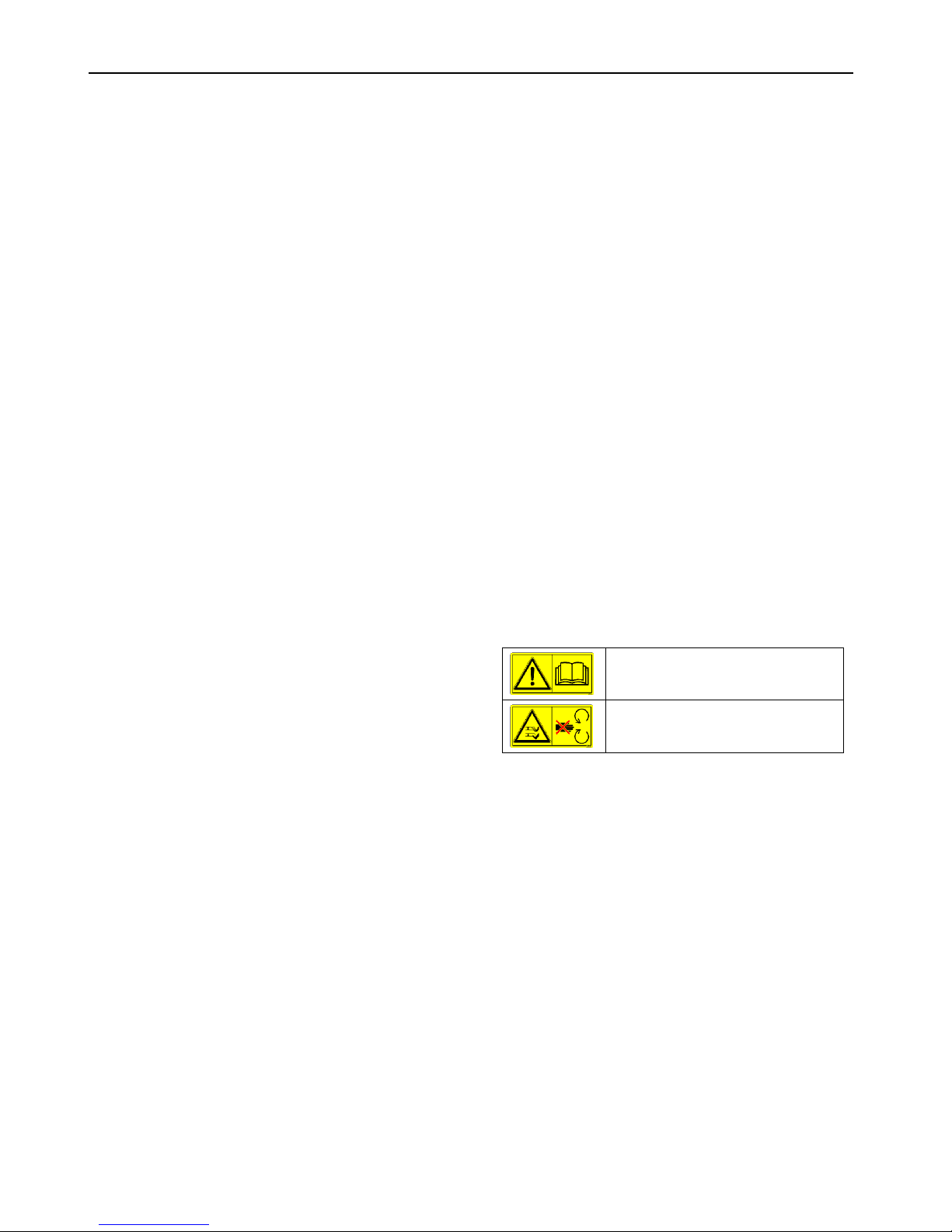
The operation manual and safety
instructions must be read and observed
prior to starting the machine.
Keep sufficient distance to mower blade
during operation.
2.8 Environmental protection
• Oils and greases shall be disposed of properly and
separately in accordance with legal regulations. Please do
not dispose of any wastes in the environment.
• Packaging materials are recyclable. Please make sure
that they are collected for reuse.
• Legacy devices contain valuable recyclable materials
which should be collected for reuse. These devices may
be disposed of through appropriate collection systems.
Page 5
TOURNO pick-up mower
Original Operation Manual English
-5
3 Design and function
3.1 Brief description
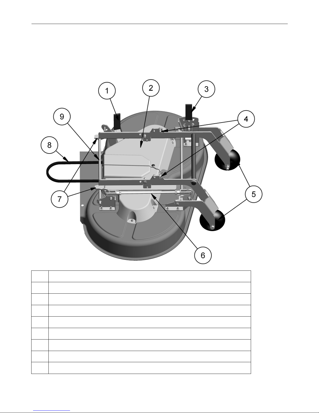
The mower front device may be used as mulcher in combination with the carrier vehicle TOURNO pick-up. The mower is mounted
on the TOURNO pick-up and operated through the operating panel. For cleaning purposes, the mower may be tilted upward in a
few simple steps.
3.2 Overview top
1 Lever for V-belt tensioning
2 V-belt protective cover
3 Adjustment lever for mowing height setting
4 Bolt with splint
5 Support wheel
6 Adjusting rod
7 Receiving point of TOURNO pick-up carrier (guide rail)
8 V-belt
9 Guide rod
Page 6
TOURNO pick-up mower
Original Operation Manual English
-6
3.3 Overview bottom
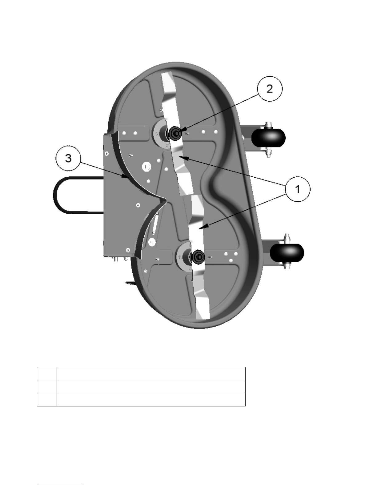
1 Blade
2 Bolted connection
3 Mulching kit
Page 7
TOURNO pick-up mower
Original Operation Manual English
-7
3.4 Operating elements
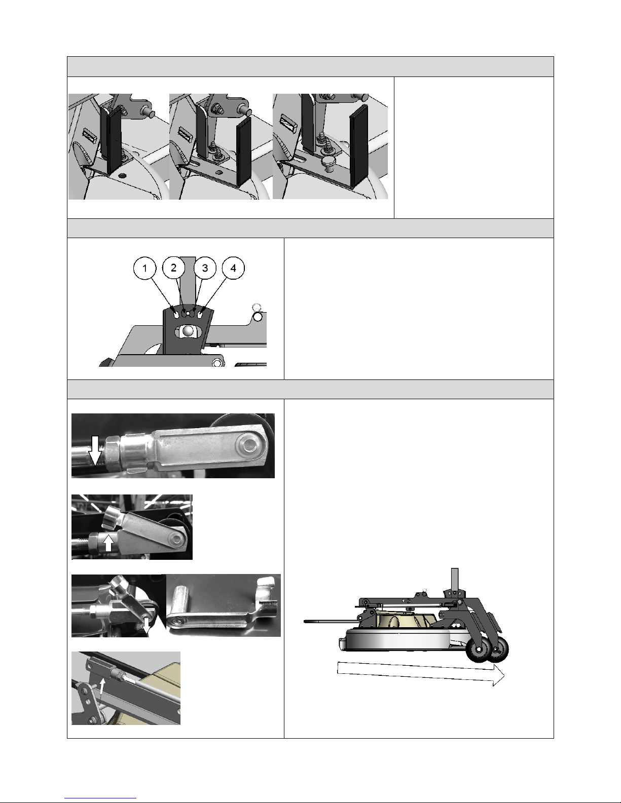
1. Lever for V-belt tensioning
The V-belt may be removed from the Vbelt disk by using the lever. Always secure
the lever by a pin inserted in the bore
holes.
Note!
The pin is included in the supply. (Please
also refer to 3.5.1)
2. Adjustment lever for setting the mowing height
Push lever slightly to the outside and let it engage at the requested
mowing height.
1 = 30 mm
2 = 45 mm
3 = 50 mm
4 = 65 mm
3. Adjustment rod for inclination setting
For optimum mulching, the mower should be inclined forward
A1: For setting, loosen the adjustment rod bolt on one side.
A2: Release the catch spring from the adjustment rod and pull it slightly
upward.
A3: Remove the catch spring from its fixture.
A4: Subsequently turn the adjustment rod until the mower inclines
forward. At the back, the mower should be 2-10 mm higher than at
the front. Subsequently tighten the bolt again.
A1: Now get the adjustment rod engaged in the catch spring again.
A 1
A 2
A 3
A 4
Page 8
TOURNO pick-up mower
Original Operation Manual English
-8
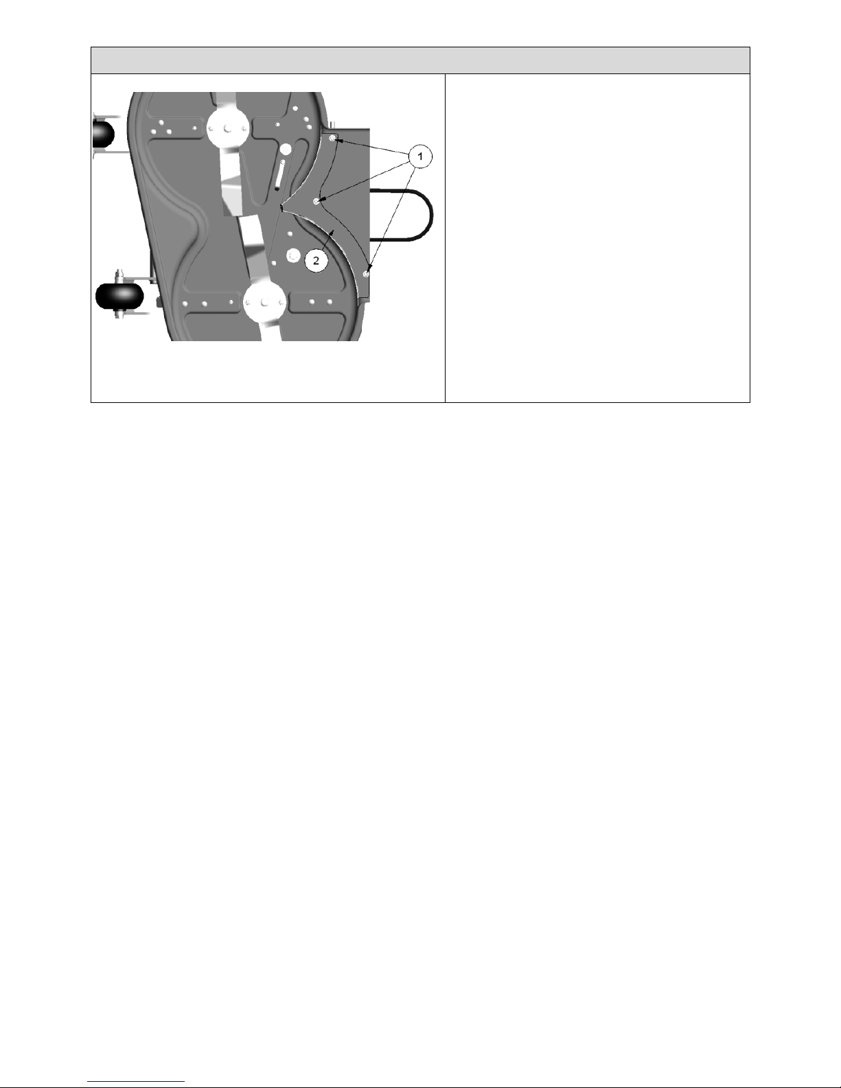
4. Remove mulching kit
1: Hexagon bolt with washer
2: Mulching kit
For discharging grass, the mulching kit below the mower may
be removed.
Please proceed as follows:
1. Stop the carrier and remove the ignition key
2. Tilt the mower upward (cf. item 3.5.1)
3. Loosen the three hexagon bolts and remove the
washers
4. Now remove the mulching kit
5. You may now tilt the mower back again.
Page 9
TOURNO pick-up mower
Original Operation Manual English
-9
3.5 Functions
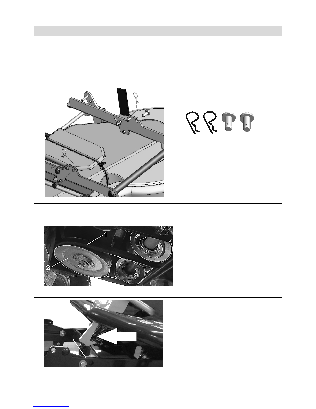
1. Tilt mower upward
For better access to the bottom of the mower, the entire mower may be tilted upward.
For tilting the mower upward, please proceed as follows:
Attention!
Stop the carrier and remove the ignition key.
Activate parking brake.
1. Set the mowing height to the lowest level (1) using the adjustment lever.
2. Before you can tilt the mower upward, the pins and the R-clip on each side have to be removed.
3. Lower the mower from the carrier perspective.
4. Pull the lever for the V-belt guide until one of the pins may be set. (Please also refer to 3.4.1)
5. Remove the V-belt from the V-belt disk. Slightly turn the disk for this purpose.
1 = V-belt
2 = V-belt disk
6. Lift the mower at the front rod and get it engaged in the securing hook on the carrier.
7. Have the second pin ready at hand
Pin with R-clip
Page 10
TOURNO pick-up mower
Original Operation Manual English
-10
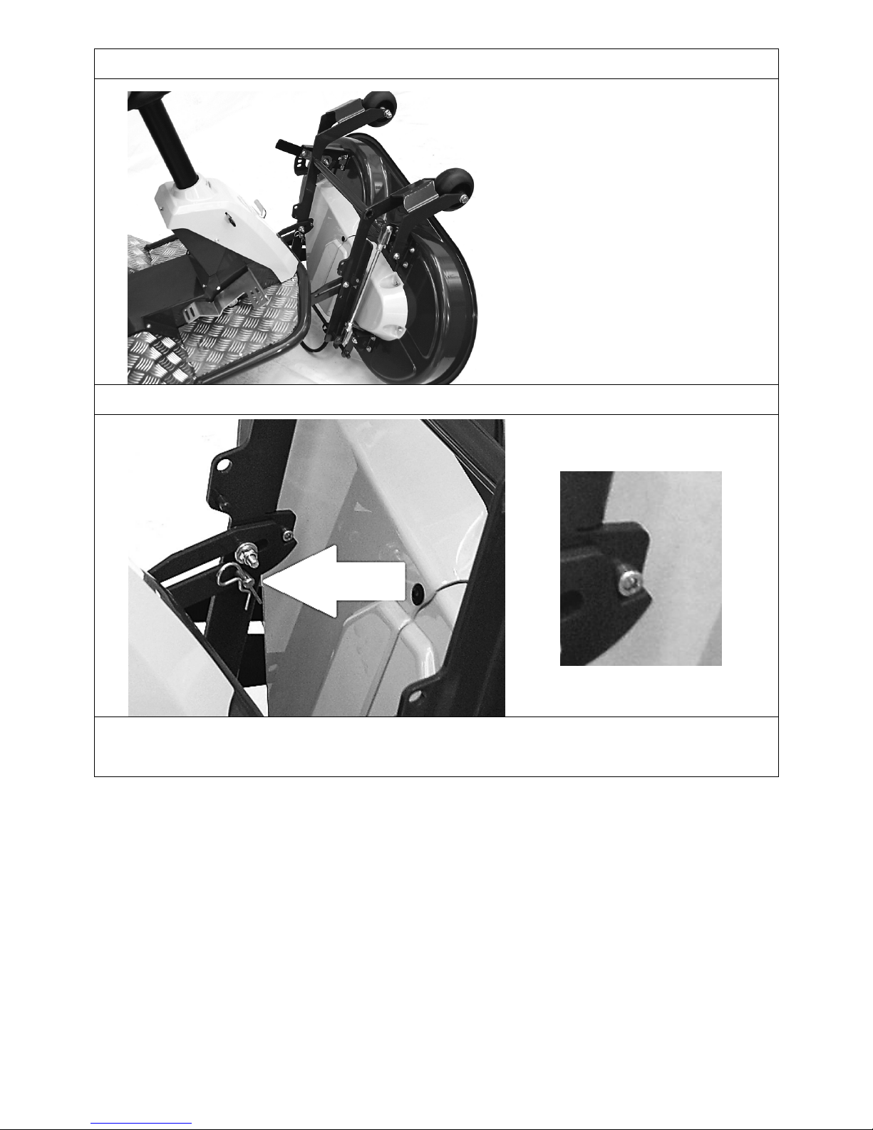
8. Slowly pull the mower towards you as far as possible.
9. Only now tilt the mower upward (inclination approx. 80°) and hold it.
10. Insert the second pin into the bore so that the mower is kept at the top.
Important! The bolted connection has to bear in the angle as shown on the right picture.
11. You may now let go the mower.
Note!
Please observe that there is sufficient distance to the floor when tilting the mower. (Damage to paint coat)
Page 11
TOURNO pick-up mower
Original Operation Manual English
-11
2. Tilt mower downward
For tilting the mower downward, please follow the procedure below:
1. Hold the mower at the rod and remove the second pin from the bore (picture in 3.5 Functions, no. 1.12).
2. You may now tilt the mower downward and push it back towards the carrier.
3. Slightly lift the mower so that you may release it from the securing hook. Subsequently lower the mower completely (picture in 3.5
Functions, no. 1.6).
4. The V-belt may now be placed on the V-belt disk again. For this purpose, turn the disk so that the V-belt adapts itself on the disk.
5. Use the splint to fix the tow pins on the mower bore again. For the exact position, see picture in 1.2 (item 3.5 Functions).
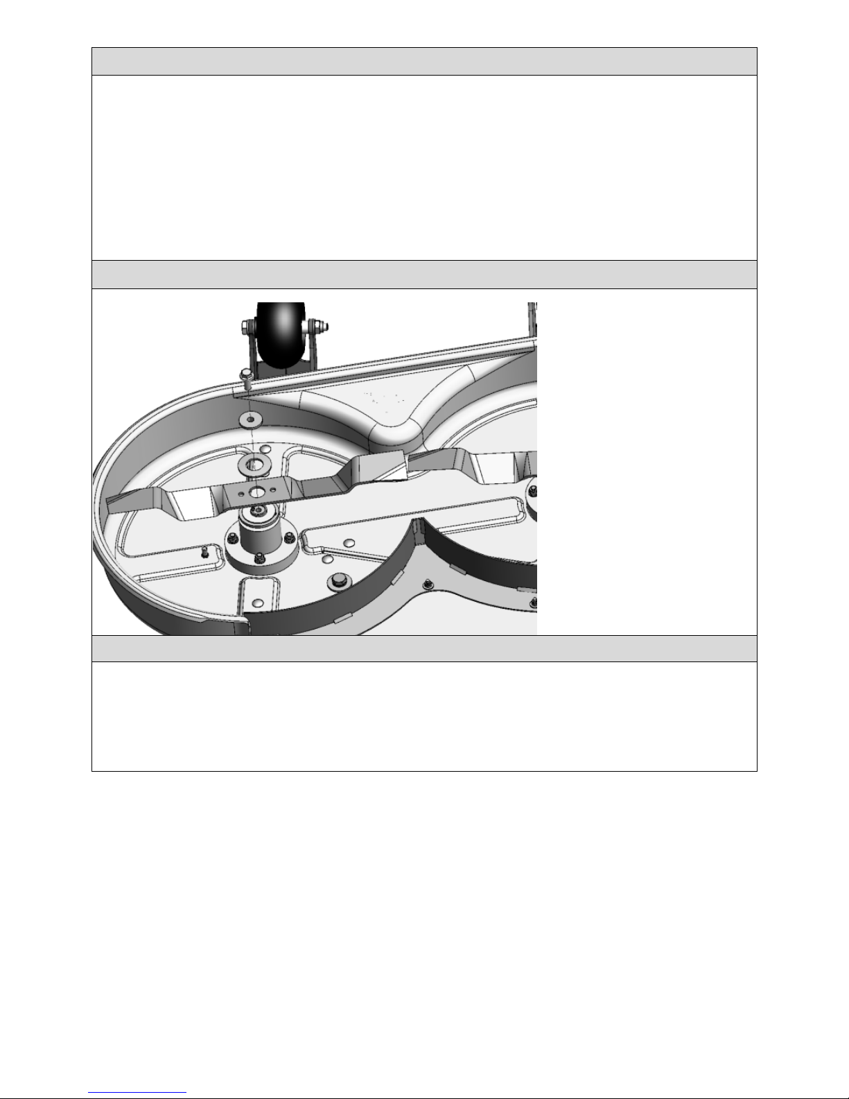
3. Dismantle blade for sharpening or replacement
In order to dismantle the blade, the bolt
has to be loosened and the two washers
have to be removed (see picture).
For remounting the blade, the washers
have to be placed in the correct sequence
and fixed with the bolt.
Important! The blades have to be
arranged as shown in the picture. Do not
forget the mounting parts!
4. Set mowing height
The mowing height should always be adapted to the current lawn length.
• If a lawn is mown regularly, the height may be set to level 2-3.
• In case of an extended mowing break (holidays), the lawn should be mown in several steps, beginning with level 4.
An insufficient mowing height will result in damage to the lawn and an insufficient mulching of the lawn.
Page 12

TOURNO pick-up mower
Original Operation Manual English
-12
3.6 Working position and areas of risk
Working position:
On the carrier
Areas of risk:
• Discharge area at front device.
3.7 Accessories and spare parts
Original parts
Only original spare parts and original accessories may be
used.
3.8 Transport
Transport without packaging
• Fix the machine by using lashing straps.
3.9 Storage
• Do not store device in the open air
• Do not expose it to aggressive materials
• Clean device with a soft brush before start up.
4 First commissioning (first inspection of front device)
4.1 Safety
Risks of non-applied protection devices
WARNING !
Risk of injuries by rotating blades!
Parts of the body may be seized when you reach into the
blades.
Lack of covers may cause injuries by flinging materials.
Do not reach into the blades during operation.
Do not open or remove any covers during operation.
4.2 Requirements at location of use
• Only mount or place front or trailer devices on even
surfaces and solid ground.
4.3 Assembly
Please refer to installation instructions in Annex before first
commissioning.
4.4 First commissioning
1. Park the TOURNO pick-up carrier on an even surface.
2. The carrier must be put out of operation.
3. Mount the mower front device on the carrier
4. The entire machine is ready for the following functions.
No use the operating elements of the TOURNO pick-up:
5. Lift the mower with the pedal.
6. Start the carrier using the ignition key.
7. Lower the mower.
The mower should now be in operation.
Should nevertheless functional failures occur, please contact
your authorized Cramer dealer.
5 Operation
Please also observe the operating element functions of the TOURNO pick-up carrier.
5.1 Normal operation
1. Basic setting
• Mount the front device on the carrier.
• Lift the mower.
2. Start the carrier.
• Lower the mower.
• Move machine across the area to be mown/mulched.
• Stop the mower and lift it.
3. Stop the carrier.
Please observe the relevant Operation Manual for handling the Cramer carrier.
Page 13

TOURNO pick-up mower
Original Operation Manual English
-13
6 Maintenance
6.1 Safety
DANGER !
Risk of injury by inappropriately performed
maintenance work!
Defective work may result in serious bodily injuries and
damage to property.
Make sure that you have sufficient working space.
Place components separately.
Remount all components.
Remount all safety covers.
Keep the risk area clear of persons.
6.1.1 Cleaning
Tilt the mower upward on the carrier for cleaning.
Please refer to item 3.5 Functions.
1. Stop the carrier and tilt the mower upward.
2. Use a brush to remove grass residues and sand.
3. Clean mower with a damp cloth as appropriate.
6.1.2 Check safety precautions
Safety precautions comprise:
- Covers of V-belts.
The mounting devices must not be operated if the covers
show any signs of damage or are removed. They are to be
replaced in case of damage or loss. The mounting devices
must not be started without safety precautions.
6.1.3 Lubrication
The wheel suspension has to be greased regularly and after
extended standstill times.
6.2 Maintenance plan
Maintenance Prior or after each use Annually Intervals in hours
25 50 100 200
Cleaning X (Item 6.1.1)
Check safety precautions X (Item 6.1.2)
Check all screws for tight seat O
Check blades for wear O
Lubrication X (item 6.1.3)
Repair paint coat damage and corrosion O
X = Described in this Operation Manual in the indicated section.
O = Not described in the present Operation Manual
Page 14

TOURNO pick-up mower
Original Operation Manual English
-14
7 Troubleshooting
7.1 Safety
Procedure for failures and accidents
1 Initiate emergency stop (leave working position).
2 Stop the carrier.
3 Determine the failure cause.
4 Remedy failure or contact authorized dealer.
7.2 Service address
Please contact your sales consultant in case of failures,
problems or otherwise. Please always indicate the Cramer
product serial no. in inquiries. (Please refer to nameplate on
the Cramer product or on the Operation Manual cover).
.
7.3 First action for troubleshooting
Failure / Error message Remedy Notes
Irregular mowing result
- Blades are blunt
- Mower inclination is inappropriate (see 3.4.3)
- Grass accumulation in mower
- Excessively high speed at insufficient motor rpm.
- Different pressure levels in wheels
Notify authorized dealer
if failure persists.
Only use original spare
parts!
V-belt slips
- Retension spring at lever for V-belt tension.
- V-belt is not flush in V-belt disks
Mower vibrates
- Tighten blade bolts
- Blades are imbalanced → replace them by new, original
blades.
8 Technical data
Pick-up mower
Machine data
Length, cm 965
Width, cm 780
Height, cm 430
Weight, kg 30
Working ground Green areas, lawn
Application area Normal use in facilities and landscaping maintenance
Cutting width, cm 90
Cutting height, cm from 30mm to 65mm
Cutting height adjustment 4 x
Number of blades 2
Type of mower Mulching / rear discharge
Connections / interfaces Receiver for mounting on carrier
Year of construction See machine nameplate
Technical modifications reserved!
Page 15

TOURNO pick-up mower
Original Operation Manual English
-15
9 Declaration of conformity
EU Declaration of conformity pursuant to machine directive 2006/42/EC Annex II 1-A
The authorized party with residence in the EU,
Cramer GmbH
Reimersstr. 36
26789 Leer
herewith declares, that the following product
Manufacturer:
Cramer GmbH
Reimersstr. 36
26789 Leer
Product designation:
Front device
Make:
Cramer GmbH
Serial number:
see cover nameplate
Type(s):
Pick-up mower
complies with all relevant regulations of the above-stated Directive as well as all other applicable Directives - including their
amendments applicable at the date of this declaration.
The following harmonized standards were applied:
EN 953:1997+A1:2009
EN ISO 12100:2010
Name and address of person authorized to compile the technical documentation:
Andre Schwarzkopf
Cramer GmbH
Reimersstraße 36
26789 Leer
Site:
Leer
Date:
28/02/2014
____________________________
_______________________________
A. Bruns
A. Schwarzkopf
Managing Director
CE Officer
Page 16
TOURNO pick-up mower
Original Operation Manual English
-16
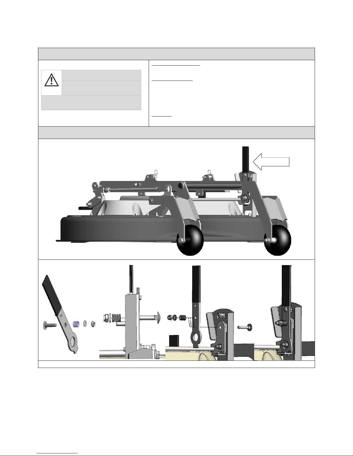
10 Mount adjustment lever for mowing height setting
Mount mower on TOURNO pick-up carrier
Dismantle mower from TOURNO pick-up carrier
Safety
Delivery, packaging, assembly
ATTENTION!
Squeezing hazard during
installation!
Parts of the body may be squeezed when
components are mounted.
Risk of high dead weight
• Remove machine parts separately from packaging.
Transport inspection
• Check the machine for completeness and potential damage upon delivery.
• The front device shall be supplied to the specialist dealer in a partially
assembled condition.
• Assembly and start-up have to be performed by a specialist dealer and/or an
expert in this field.
Packaging
• Please dispose of packaging materials separately.
A1: Mount adjustment lever for mowing height
Mount all parts indicated and tighten them with hex-nut
Page 17
TOURNO pick-up mower
Original Operation Manual English
-17
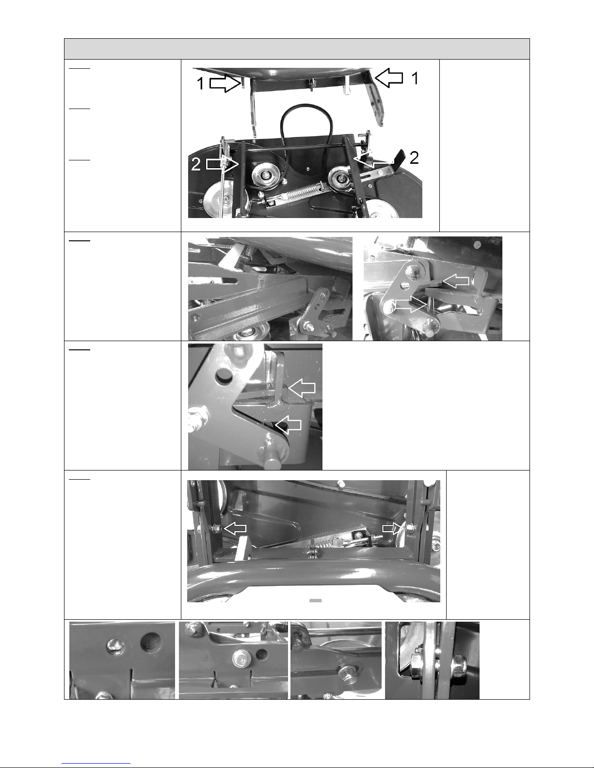
A2: Mount mower on TOURNO pick-up carrier
Step 1
Place the mower in front of the
carrier.
Step 2
Pull the lever for tensioning the
V-belt and fix it with a pin (see
3.4.1).
Step 3
Lift the mower at the back and
place the guide rail on the
receiver bar.
1 Receiver bar
2 Guide rail
Step 4
Position both sides of the guide
rail and the guide rod as shown
in the picture.
Step 5
Now entirely push the mower
on the receiver bar.
The guide rail nib must be
engaged in the receiver bar
slot, the guide rail must be
placed in the fixture.
Step 6
Place one washer on the bolts
and push the latter through the
bore (PICTURE) on both sides of
the guide rail.
Place another washer at the
other end and fix it with the
hex-nut with some backlash.
The following parts
are fixed on the
mower:
2 x bolts
4 x washers
2 x hex-nut
Page 18
TOURNO pick-up mower
Original Operation Manual English
-18
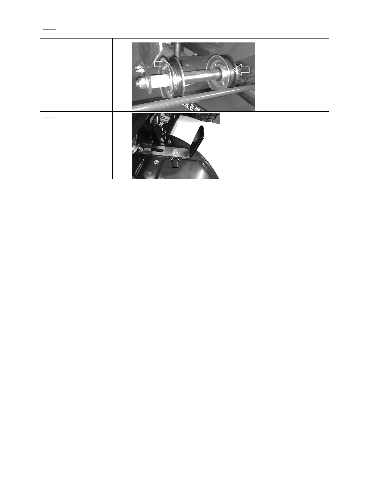
Step 7
Now lower the mower with the pedal and the pedal unlocking.
Step 8
Only then place the V-belt on
the V-belt disk.
Important! The V-belt must be
in the guide of the two lateral
V-belt disks.
Step 9
Slightly pull the lever for
tensioning the V-belt, remove
the pin and slowly release the
lever.
Page 19
TOURNO pick-up mower
Original Operation Manual English
-19
A3: Dismantle mower from TOURNO pick-up carrier
Step 1
Now lower the mower with the pedal and the pedal unlocking.
Step 2
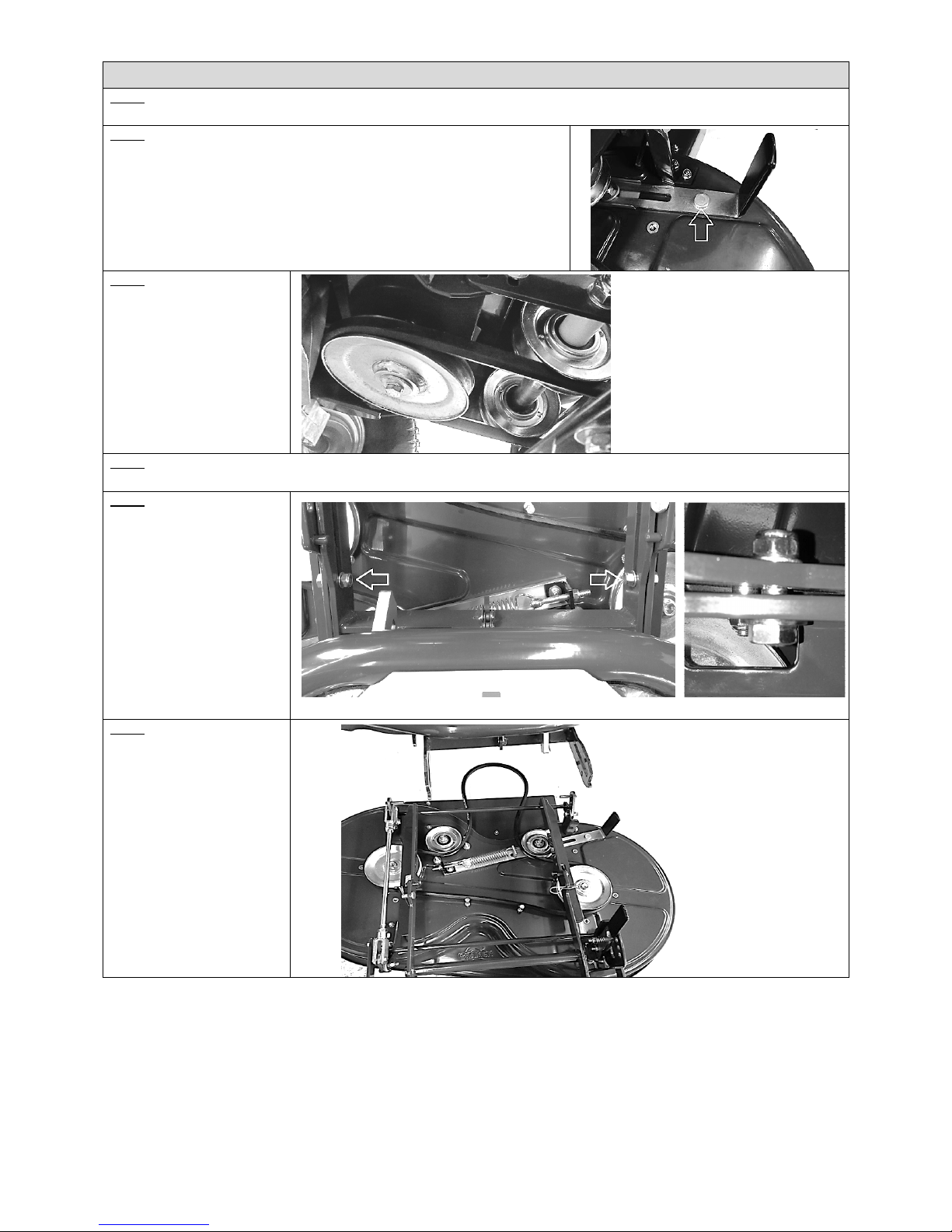
Pull the lever for tensioning the V-belt and fix it with a pin (see 3.5.1).
Step 3
Remove the V-belt from the Vbelt disk. Do not take off V-belt
completely.
Step 4
Lift the mower with the pedal and get it engaged in the pedal lock.
Step 5
Remove the two bolts at the
right and the left of the receiver
bar.
Step 6
The mower may now be pushed
from the carrier.
 Loading...