

CRAIN 825V, 825 Instruction Manual
1812-P
18
1812-Q
01
19
03
02
04
04
10
03
11
14
1820-R1
1820-S
1820-O
1820-Y
1820-N
1820-P
15
16
1820-H
17
22
22
08
21
20
1812-O
1555-P
1812-R
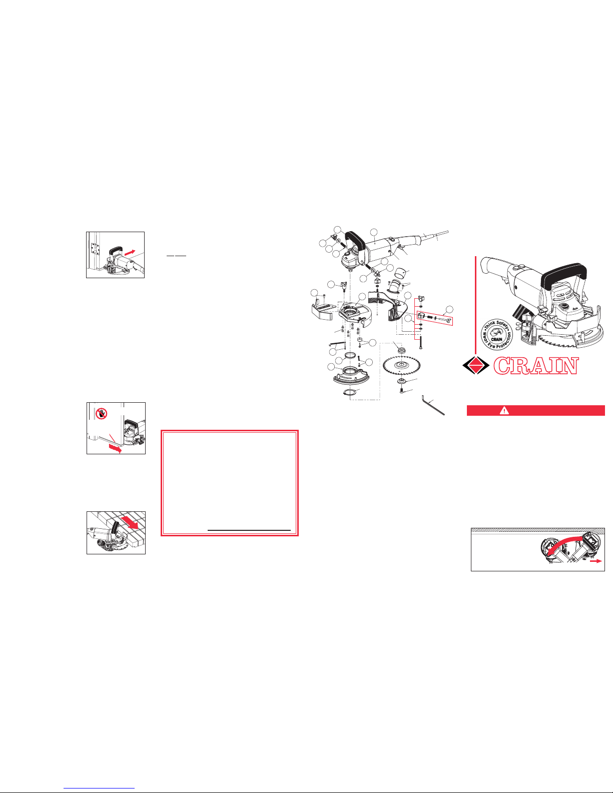
NO. 825 HEAVY-DUTY UNDERCUT SAW
Order No. Description Order No. Description
1825-01 Power Unit, 120 V
1825-01V Power Unit, 220V
1825-02 Ratchet Handle
1825-03 Handle Three-Arm Knobs (2)
1825-04 Handle Threaded Studs (2)
1825-08 Depth Gauge Three-Arm
Knob
1825-10 Height Adjuster Three-Arm
Knob & Fasteners (5)
1825-11 Guide Washer &
Fasteners (4)
1825-14 Height Adjuster
1825-15 Housing
1825-16 Depth Gauge & Fasteners (2)
1825-17 Stopper & Screw
1825-18 Hooked Spring & Screw
1825-19 Blade Guard Sleeve
1825-20 Blade Guard
1825-21 Flared Spring & Screw
1825-22 Handle Washers (2)
1820-H Housing Fastener Set (4)
1820-N Dust Port w/Screws (4)
1820-O Power Cord Only
1820-P Dust Port Cap
1820-R1 Switch Type B, Black
1820-S Brushes (not shown)
1820-V Brush Holder Assembly plus
Brushes (not shown)
1820-Y Strain Relief Only
1555-P Snap Ring
1812-O Blade Spacer
1812-P Blade Clamp
1812-Q Blade Screw
1812-R 5mm Allen® Wrench
NOTE: The maximum thickness of cut is 15/8", which
is adequate for most doors. Check for adequate depth
of cut before starting. Thicker doors may require cuts
from both sides of the door. Take care not to leave a thin
remnant of door on the opposite side, which can easily
break off and crack the veneer. Also, check that the
oor is at the same elevation on both sides of the door,
or additional height adjustment may be required.
The maximum height of cut is one inch. To cut off
higher than one inch, pla ce a at sheet of plywood
underneath the saw.
INSTRUCTION
MANUAL
REPLACEMENT PARTS
Some dust created by power sanding, sawing, grinding,
drilling, and other construction activities contains chemicals known to the State of California to cause cancer, birth
defects or other reproductive harm. Some examples of
these chemicals are:
lead from lead-based paints,
crystalline silica from brick, cement and other
masonry products, and
arsenic and chromium from chemically-treated
lumber.
Your risk from these exposures varies, depending on how
often you do this type of work. To reduce your exposure to
these chemicals: work in a well-ventilated area, and work with
approved safety equipment, such as those dust masks that
are specially designed to lter out microscopic particles.
GUARANTEE
This Crain No. 825/825V Heavy Duty Undercut Saw
is guaranteed to be free of defects in workmanship
and quality of materials for a period of one year.
Any parts of this saw found defective subject to the
guarantee will be replaced at no charge. Credit in
full or part cannot be extended by the distributor,
nor will a new saw be given as a replacement or
loaner.
Saws subject to this warranty must be accompanied
by same, returned freight PREPAID to Milpitas, CA,
and must be in assembled condition.
DATE OF MFG.
Printed by: HF FORM F1825-Rev.02/10
Milpitas, CA 95035 TEL: (408) 946-6100
www.craintools.com
CRAIN CUTTER CO., INC.
SPECIFICATIONS:
POWER UNIT Model No. 825 Model No. 825V
Voltage: 120VAC, 60 HZ. 220VAC, 50HZ
Construction: Double Insulated Double Insulated
Plug Type: 3-Prong Plug UK Plug
Amperes: 8.15 Amps 4.1 Amps
Wattage: 930 Watts 930 Watts
No Load Speed: 6,500 RPM 6,500 RPM
Max Depth of Cut: 15/8" 15/8"
Max. Height of Cut: 1" 1"
Toe Space Cutting Specications:
Minimum Height / Maximum Depth: 31/2" / 31/2" 31/2" / 31/2"
Gross Weight: 17.4 LBS. 17.4 LBS.
Replacement Blades for both No. 825 / No. 825V: #821 Carbide-Tipped Blade, #805 Masonry
Blade, #822 Diamond Blade
WARNING:
Take precautions necessary
for veneer doors and check
door thickness as described
above (under "Door Cutting").
Pocket door cutting requires
two people. One must hold
the saw down and in a xed
position, while the other person slowly pulls the door
into the blade. DO NOT LIFT
DOOR OR THE SAW WHILE
CUTTING OR KICKBACK MAY RESULT!
Remove any unnished area at the bottom of the
pocket door with a hand saw, following along in the
pre-established cut.
If saw is dropped, the blade guard may be bent or otherwise
damaged, restricting full return. Sawdust that accumulates behind the blade guard will cause it to become clogged, especially
drywall dust. Check operation of the blade guard before each
use. Do not use the saw if the blade guard does not operate
properly. When not in use, store saw in the custom carrying
case. The saw motor may run even if the switch malfunctions,
causing the motor to not switch off. Do not use saw if the
switch malfunctions. Repair the switch immediately!
MAINTENANCE:
Figure 16
MASONRY, STONE, OR TILE UNDERCUTTING:
POCKET DOOR CUTTING:
The No. 805 Masonry Blade
is primarily used for cutting
brick. It is not for use on tile
or stone. Use the No. 822
Diamond Blade for c utting
brick, tile or stone.
Masonry, stone, and tile undercutting creates a lot of
dust. We strongly recommend the operator wear a dust
mask and place a light cloth over the air intake on the
motor. This will prolong the life of the saw.
DO NOT use this saw for cutting steel or aluminum. Sparks
can cause re in the wall behind the door casing.
Figure 17
KICKBACK HAZARDS:
•
THIS SAW PLUNGE-STARTS. PLUNGE SLOWLY BE-
FORE PUSHING FORWARD!
•
KEEP RPMs HIGH. DON’T FORCE THE SAW, ESPE-
CIALLY WHEN NAILS MAY BE PRESENT.
•
HEIGHT ADjUSTMENT: KEEP THE BLADE HOUS-
ING FLAT ON LEVEL FLOORS, AND KEEP BLADE
PARALLEL TO THE FLOOR AT ALL TIMES.
•
ALWAYS PUSH SAW AGAINST BLADE ROTATION.
NEVER PULL TOWARDS YOU OR RUN IN REVERSE.
WARNINGS:
KEEP KNEES AND OTHER
BODY PARTS OUT OF KICK
BACK ARC.
KNEEL TO THE SIDE!
DO NOT USE STANDING UP!
SAFE OPERATING POSITION:
A
R
C
CUTTING DIRECTION
No. 825/825V
HEAVY-DUTY UNDERCUT SAW
CAUTION!
BLADE EXPOSED
KEEP HANDS
& FEET AWAY
FROM CUT!
PULL DOOR
IN THIS
DIRECTION
HOLD SAW
STATIONARY
Open the door to the maximum, away from the casements. Work from the inside
of the door outward, away
from the hinges. To avoid
splintering veneer doors, it
may be advisable to score
the veneer surface at the desired height of the cut, prior
to using the saw. An application of wide masking tape in the cutting zone also helps
reduce splintering, and will protect the saw housing from
scratching the veneer. DO NOT MOVE OR LIFT DOOR
WHILE CUTTING OR KICKBACK MAY RESULT!
DOOR CUTTING: see Figure 15
Figure 15
•
IN USE, KEEP ONE HAND ON THE SWITCH HANDLE
AND ONE HAND ON THE RATCHET HANDLE. DON’T
REMOVE A HAND TO CLEAR DEBRIS.
DUST
CONTROL
Place the saw at on the oor
near the wall to be undercut.
Make cert ain blade is set
parallel to the oor.
Make sure the blade holding
screw, and height locki ng
wing screws are tightened
sec urely. Ha ndle ra tche t
teeth should interlock and
three-arm knobs be tight-
ened securely (gure 10).
Always keep the handle in
the vertical position for general undercutting.
Lower the handle for under-
cutting toe spaces (gure 11). Be sure to lock knobs.
Plug in the saw and grasp handles rmly with both hands.
Keep one hand on the switch handle and one hand on the
ratchet handle at all times. Depress the safety lock button,
then pull the power switch.
To start a cut, use the wall to push the blade guard back
and expose blade. DO NOT USE YOUR HAND!
First, plunge slowly to appropriate depth. Second, push
the saw forward. Move the saw from left to right only.
Don't force the saw; let blade cut at highest RPM possible. Do not pull the saw towards you or run in reverse.
Do not lift or angle the saw or kickback may result.
Remove the saw from the cut, and release the switch to stop.
Turn off and unplug saw.
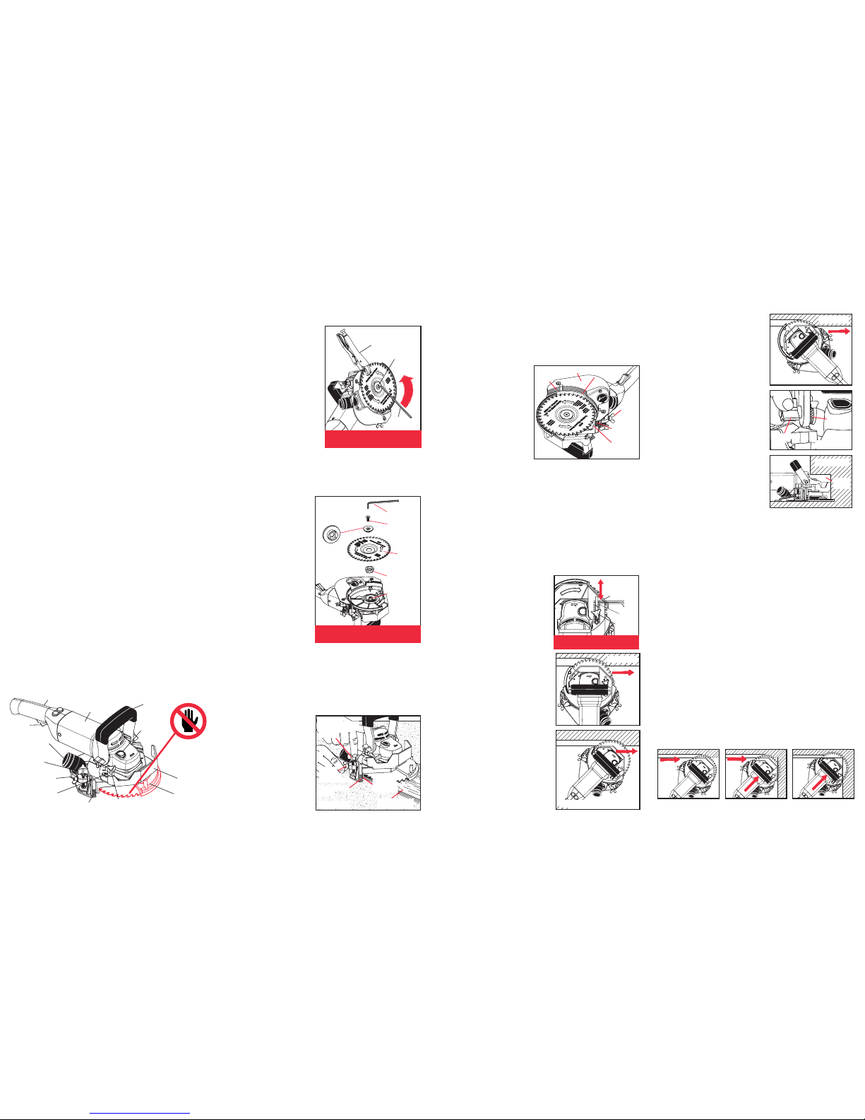
Retract the height adjuster
so it is ush with the housing to allow clearance for
the Allen® wrench.
Pus h the spin dle lock
button with one hand and
insert the Allen® wrench
into the blade screw with
other hand; then turn the
Allen® wrench u ntil the
spindle engages with the
lock button (bl ade will
stop rotating).
Hold onto the plastic housing, then push hard on the Allen® wrench counter-clockwise to open. If the blade is
hard to remove, use a Vise Grip® to hold the blade.
Figure 3
SAFETY FIRST
HANDLES:
In use, keep both hands on the handles at all times.
KICKBACK HAZARDS: While cutting, do not force the
saw. Also, keep the housing at on the oor and the blade
parallel to the oor at all times. Angling may cause powerful,
dangerous kickback. Keep the saw RPMs high. Using a
dull blade will place a heavy load on your saw and increase the
danger of kickback. Use only Crain replacement blades.
EYE & EAR PROTECTION: Always wear safety glasses when
using a power tool. Wear ear plugs when using this saw.
BLADE GUARD: The blade guard attached to your saw is
for your safety and protection. If it becomes damaged, do
not operate your saw until it has been repaired. Keep the
blade guard in operating condition when using the saw.
DOUBLE-INSULATED: This tool is constructed with two
separate layers of electrical insulation. A tool built with this
insulation system does not need to be grounded.
DANGEROUS ENVIRONMENTS: Keep work area clean;
clutter invites accidents. Do not use the saw on damp or
wet oors. Be sure that there is good lighting. This saw
may throw sparks. Make certain that ammable materials,
especially explosive vapors, are not present. Use face or
dust mask if cutting operation is dusty.
ACCIDENTAL STARTING: To avoid accidental starting, do
not carry tool while plugged in or with ngers on switch.
CORD ABUSE: Never carry tools by the cord or yank the
cord to disconnect from an outlet. Keep cords away from
heat, oil, and sharp edges.
EXTENSION CORD: To minimize power loss and prevent
overheating, use maximum of 25 feet long and 16 AWG.
HAIR & CLOTHING: Keep all loose hair and clothing away
from the spinning blade at all times.
The Heavy-Duty Undercut Saw is designed for undercut-
ting afxed wooden door jambs, moldings, base, as well
as masonry and stone, to allow new oor coverings to be
t underneath. Do not use this saw for sanding oors,
cutting metal, or any other purpose not described in this
instruction manual.
WORKING TERMINOLOGY: Figure 1
BLADE INSTALLATION: see Figure 3
BLADE HEIGHT ADJUSTMENT: see Figure 4
A depth gauge adjustme nt scale is engraved on the
depth gauge with twelve 1/8" increments (gure 6).
We recommend the depth of
cut be set to no more than 1/2"
to minimize the chance of hitting wall studs, nails, etc.
Whe n und ercut ting wo od
base, set depth to cut wood
on ly. C ut ti ng she etro ck
makes dust that can damage the saw over time.
To adjust the depth gaug e,
lo osen the dep th ga uge
three-arm knob and slide the
depth gauge in or out.
The depth adjuster accurately
controls the depth of cut at
any of three angles: straight-
on (gure 7), 45˚ left (gure 8),
or 45˚ right (gure 9).
Cutting at a 45˚ angle is easiest
to push the saw (gure 8).
For dust control, cutting at the
45˚ right angl e is preferred.
This angle captures as much
dust as poss ible inside t he
housi ng. When using this
saw with a vacuum, this is
DEPTH ADJUSTMENT:
Unplug the saw. Loosen the two height locking wing
nuts one to two turns.
Turn the two height adjustment three-arm knobs clockwise to increase blade height and counter clockwise to
decrease height.
It is best to turn both
height adjustment threearm knobs at the same
time to ensure the blade
is set parallel with the
oor.
Both the front of the
height adjuster and the
inside of the height ad-
Figure 9
Figure 11
Figure 8
Figure 10
Figure 7
CAUTION!
BLADE EXPOSED
WHILE CUTTING
KEEP HANDS
AWAY!
SWITCH
RATCHET
HANDLE
MOTOR
HOUSING
DEPTH GAUGE
ADJUSTMENT
SCALE
HEIGHT LOCKING
WING SCREW
DEPTH GAUGE
THREE-ARM KNOB
BLADE
GUARD
DEPTH
GAUGE
SPINDLE
LOCK
BUTTON
Figure 12
Figure 13
Figure 14
Cut towards the corner at 45˚ angle (see gure 12) until
the depth gauge meets the right wall (see gure 13).
Stop and unplug saw. Fully retract depth gauge and
continue the cut.
Push saw into the corner as shown (see gure 14).
WARNING: Depth gauge covers the blade and makes the
saw safer to use. Always unplug the saw and reset the
depth gauge when inside corner cutting is complete.
INSIDE CORNER CUTTING:
Figure 2
BLADE REMOVAL: see Figure 2
BEST FOR
PUSHING
DUST
CONTROL
HEIGHT
ADJUSTMENT
THREE-ARM
KNOB
REFERENCE
LINES
USING THE SAW:
Figure 6
DEPTH GAUGE
THREE-ARM
KNOB
0"
1
/2"
1
/4"
EACH
LINE IS 1/8"
DEEP
45º LEFT
ANGLE
SWITCH HANDLE
STRAIGHT
ON
45º
RIGHT
ANGLE
ALLEN®
WRENCH
Unplug the saw.
Place the blade spacer over the spindle.
Place the blade on top
of the blade spacer.
Place the blade clamp
through the arbor hole
of the blade with the
bo tto m slot o f the
blade clamp properly aligned wit h the
spindle.
Insert and re-tigh ten
the blade screw. Push
in the spindle lock to
tighte n. Be sure to
tighten rmly before use.
BLADE
SPACER
ALLEN®
WRENCH
BLADE
SCREW
BLADE
CLAMP
#821,
#805, or
#822
MUST
ENGAGE
SPINDLE
SPINDLE
UNPLUG THE SAW. REMOVE ALLEN®
WRENCH BEFORE STARTING.
UNPLUG THE SAW. REMOVE ALLEN®
WRENCH BEFORE STARTING.
VISE
GRIP®
BLADE
SCREW
Figure 4
juster have 10 reference lines, in 3/32" increments (.093", one
blade thickness - gure 5).
Max. height is 1".
To prevent saw kickback, the blade must be set parallel to the
oor. This can be ensured by checking from the front of the
saw that, on BOTH sides of the blade housing, the number
of lines below the bottom
edge of the blade hous-
ing are the same (gure 4)
,
OR by turning the saw
over and making sure the
bottom edge of the blade
housing is completely
parallel with a reference
line (gure 5).
It may be easiest to set
the saw blade at on
top of the new ooring
to be t beneath the desired undercut, and turn the height
adjuster three-arm knobs clockwise until the height ad-
juster rests at on the oor. From that point, for a snug t
with the new oor, adjust height down by one reference
line (one blade thickness).
Securely tighten the height locking wing screws before use.
HEIGHT ADJUSTER THREE-ARM
KNOBS
HEIGHT
LOCKING
WING SCREW
BOTTOM
EDGE OF
HOUSING
REFERENCE
LINES
NEW FLOOR TO
BE INSTALLED
HANDLE REMOVED FOR CLARITY -
DON’T USE WITHOUT HANDLE!
REFERENCE
LINES
REFERENCE
LINES
WING
SCREW
HEIGHT ADJUSTER BOTTOM EDGE
OF HOUSING
BOTTOM
EDGE OF
HOUSING
RATCHET
TEETH
THREE-ARM
KNOB
the most effective angle to
control dust (gure 9).
Re- tigh ten the thre e-ar m
knob rmly before use.
Figure 5
TOE
SPACE
 Loading...