

CRAIN 812, 812V Instruction Manual
INSTRUCTION
MANUAL
FOR
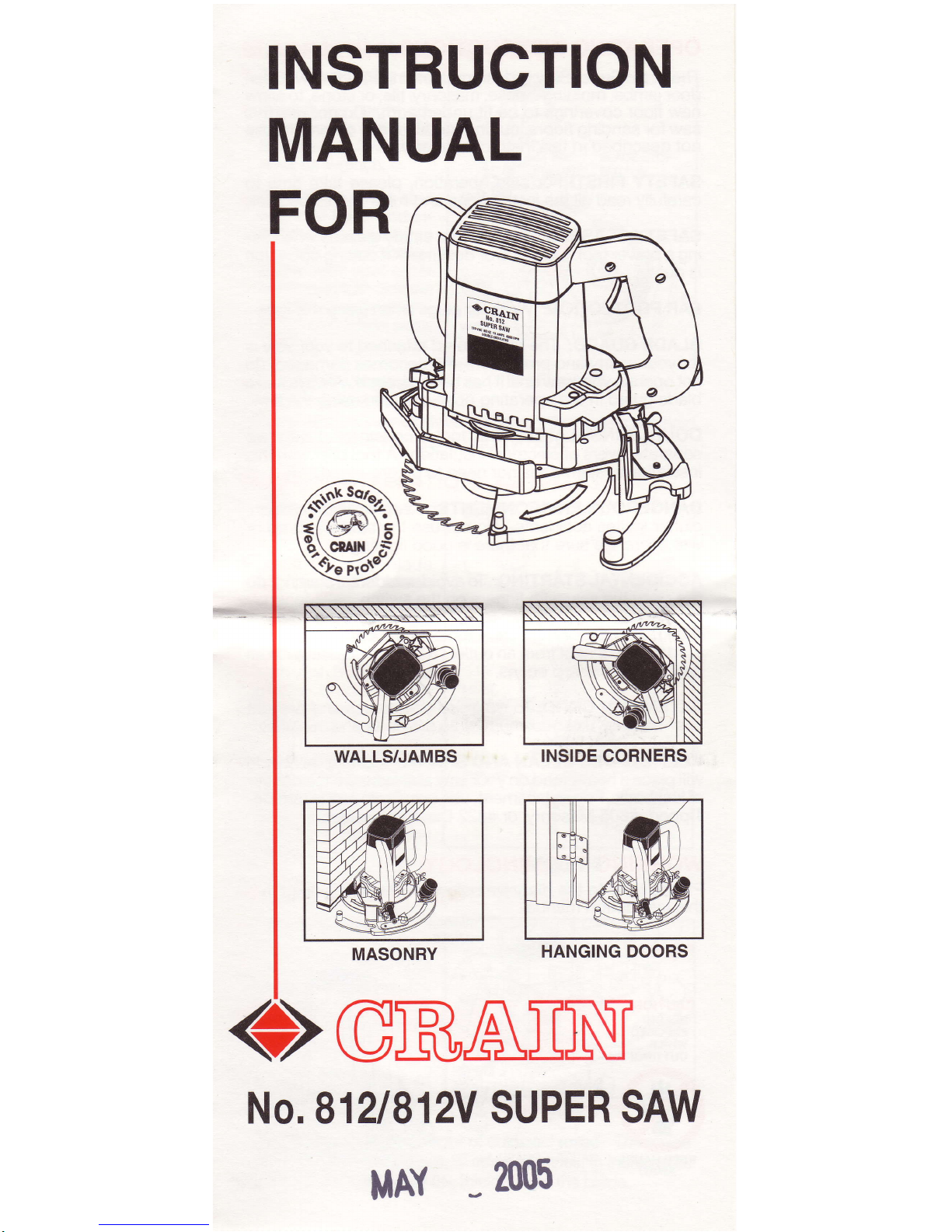
MASONRY
HANGING DOORS
OGRAilN$
No. 8121812V
SUPER
SAW
MAY
-
2005

OPERATI NG I NSTRUCTIONS
The
Crain Super
Saw
is
desiqned
for
undercuttino
wooden
door
jambs,
rholdings,
base,inasonry, tile,
orston6, to
allow
new floor
coverings to
be
fit
underneath. Do not
use
this
saw for sanding floors,
cutting metal, or
any other
purpose
not described in this
instruction manual.
SAFETY FIRST! For
safe operation,
please
take time
to
carefully read
allthe
instructions and
rules in this
booklet.
SAFEW
GLASSES:
Always wear
safety
glasses
when
us-
ing a
power
tool.
Useface or dust mask if
cutting operation
is
dusty.
EAR PROTECTION:
Wear
ear
plugs
when
using this
saw.
BLADE
GUARD:
The
blade
guard
attached to
your
saw
is
for
your
safety and
protection.
lf it becomes
damaged, do
not
operate
your
saw until it has been repaired.
Always leave
blade
guard
in the operating
position
when
using the saw.
DOUBLE-INSULATED: This tool is
constructed with two
separate
layers
of electrical
insulation.
A tool
built
with this
insulation
system
does not need to be
grounded.
DANGEROUS ENVIRONMENTS: Keep work
area clean;
clutter
invites
accidents.
Do not
use
the
saw on damp or
wet floors. Be sure that there is
good
lighting.
ACCIDENTAL
STARTING:
To
avoid accidental starting,
do
not
carry
the
saw
with
fingers on
the
switch.
CORD
ABUSE: Never
carry
tools
by
the
cord or
yank
the
cord to disconnect from an outlet. Keep the cord
awayfrom
heat, oil, and sharp
edges.
EXTENSION
GORD:
To minimize
power
loss
and
prevent
over-heating, use maximum
of
25 feet long
and
16 AWG.
KEEP BLADES
CLEAN
AND
SHARP: Using a dull blade
will
place
a
heavy load
on
your
saw and
increase
the danger
of
kickback. For replacement,
use only Crain
#821
Carbide-
Tipped,
#805 Masonry or #822 Diamond Blades.
WORKING TERMINOLOGY
Please refer to the
diagram below for the terms
used
in
this instruction manual.
TRIGGER
HANDLE
Figure 1
CAUTION!
BLADE
EXPOSED
WHILE
CUTTING!
KEEP HANDS
AWAY!
HEIGHT
BLADE
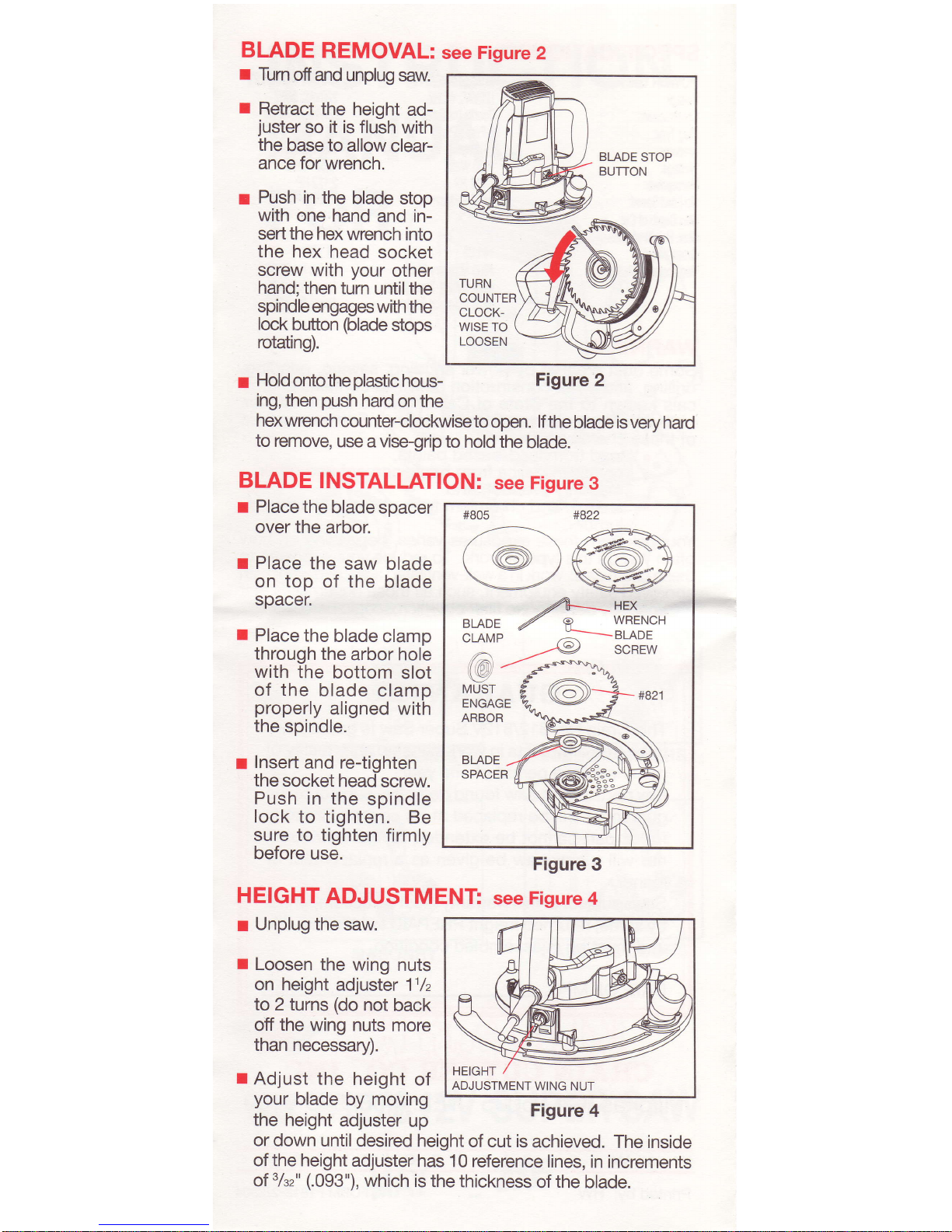
REMOVAL:
I
I
Turn
ofiand
unplug
saw.
r
Retract
the height
ad-
juster
so it is
flush
with
the
base to
allow
clear-
ance for
wrench.
r
Push
in the
blade
stop
with
one hand
and
in-
sert the hex
wrench
into
the
hex head
socket
screw
with
your
other
hand; then
turn
until the
spindle engages
with the
lock
button
(blade
stops
rotating).
r
Hold
ontotheplastic
hous-
ing, then
push
hard
on
the
Figure
2
hex wrench
counter-clockwise
to
open. lf the
blade is very
hard
to remove,
use
a vise-grip to
hold the
blade.
BLADE
INSTALLATION:
see Fisure
3
r Place
the
blade spacer
over
the
arbor.
r Place
the
saw blade
on top
of the
blade
spacer.
r
Place
the
blade
clamp
through
the
arbor hole
with
the
bottom
slot
of
the
blade clamp
properly
aligned with
the
spindle.
I
Insert
and re-tighten
the
socket head
screw.
Push
in the
soindle
lock to
tighten.
Be
sure to tighten
firmly
before
use.
HEIGHT
ADJUSTMENT
Figure
3
see Figure
4
r
Unplug the
saw.
r
Loosen
the wing
nuts
on height
adjuster
11lz
to
2 turns
(do
not
back
off the wing
nuts more
than
necessary).
r
Adjust the
height
of
your
blade
by moving
the height
adjuster up
or
down until
desired height
of cut is
achieved.
The inside
of the height
adjuster
has 10 reference
lines,
in increments
of
3/sz"
(.093"),
which is
the thickness
of
the
blade.
see Figure
2
24-_aex
BLADE
Z P
WRENCH
CLAMp
;=-BLADE
/HlVlT
/-A
,t=,-, ,./--e
SCREW
l/,61
--.-
ss-s's'$.\A-
\l \\U.t/ s- .
"lA
\lz
A ,^\ %
MUST
ENGAGE
ARBOR
#821
ADJUSTMENTWING
NUT
Figure
4
 Loading...