

Page 1
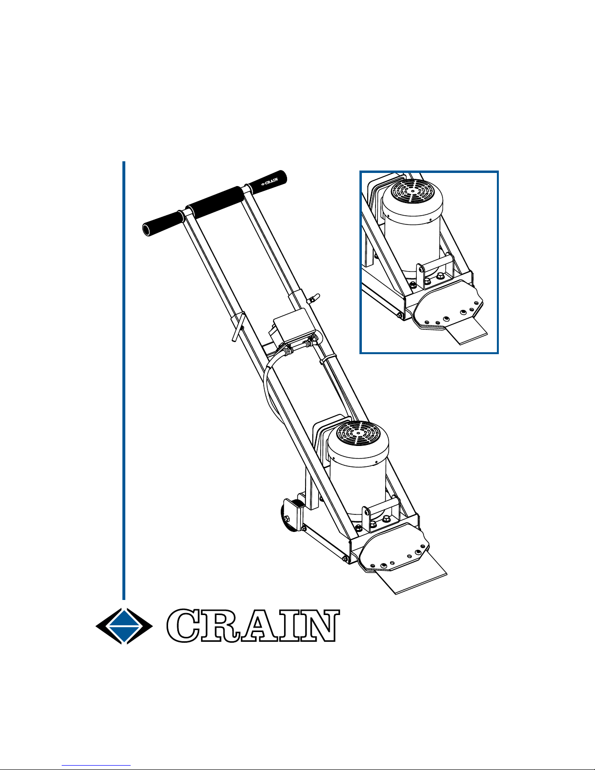
NO. 718
POWER SCRAPER
INSTRUCTION
MANUAL
FOR
THIN SPUD BLADE
Page 2

1
OPERATING INSTRUCTIONS: Read and save all instructions!
SAFETY FIRST: Use machine in accordance with instructions only!
� Blades are extremely sharp. Use extreme caution when loading and unloading
blades from the blade carrier. The use of protective gloves is advisable during
blade change. In use, keep away from the blade and oscillating blade carrier.
� Before changing blades or servicing the machine, the machine must be switched
OFF and UNPLUGGED. When changing the blade, place a short wood block
under the machine to hold the blade carrier off the oor surface. DO NOT lean the
machine back on its extendable handle for changing a blade, as this can result
in unexpected tipping forward or other unexpected motion.
� Keep all body parts at a safe distance from the blade when the motor is running,
including those of helpers or bystanders. Keep feet and hands out from under
the machine. WARNING: after the motor is switched off, the internal mechanisms
and blade may continue oscillating for a short period of time. Keep away!
� A blade should be loaded in the blade carrier during the stripping operation ONLY.
Blades should be removed and safely stored during transportation and storage.
� Wear safety glasses, ear protection and gloves. This machine produces dust.
Exposure to all kinds of dust can cause respiratory ailments. Check material to be
removed to determine if it contains asbestos or other materials that are hazardous
to be inhaled. Asbestos-containing materials should be removed by accredited
abatement professionals. Use approved NIOSH or OSHA respirators, and provide
adequate ventilation to eliminate or maintain dust below the threshold limit value
for nuisance dust as classied by OSHA. Paper masks may not be adequate.
� Keep hands and ngers away from the motor fan cover. Internal fan can cut off
ngers if contacted!
� Keep children and bystanders out of the work area. This machine is not to be
used by children or persons with reduced physical, sensory or mental ability, or
that lack experience and knowledge. DON'T ALLOW RIDERS ON THE MACHINE!
� DANGEROUS ENVIRONMENTS: Use and store this machine only in dry areas.
Don't expose to rain or incursion of any liquids. Liquids in internal parts particularly motor, switch, and cords can create a shock hazard! Do not operate the
machine when the oors in the area are wet. Don't use machine where ammable
objects or explosive gases may be present, as the machine can throw sparks.
Make sure the work area is well lit. Remove nails from the oor prior to using the
machine. When operating over a concrete suboor, beware of expansion joints
or other obstructions that can cause the machine to stick and stop unexpectedly
or kick back. Keep the machine and blade a good distance from oor mounted
electrical receptacles. Inspect for and keep clear of covered or hidden wiring.
� ACCIDENTAL STARTING: The switch of your machine should be checked to
determine that it is in proper working condition before each use. If the switch
becomes damaged, repair it immediately before further use. Make sure that the
machine is switched OFF before connecting it to power.
� GROUNDING: The cord of this machine includes a three-prong plug for grounding.
Page 3
2
DO NOT remove the ground pole for use in a two-prong outlet. If necessary, use
an adaptor to a two prong plug, and always ensure proper grounding. Plugging
in to a GFI outlet is recommended. Make sure extension cords are grounded.
� CORD ABUSE: In operation, use caution not to step on the cord (or any attached
extension cord). Also use caution not to cut the cord (or any attached extension
cord) with the blade. Don’t yank the cord to remove the plug from the electrical
socket or any other reason. For best performance, we recommend that 14 gauge
or heavier extension cords be used with this machine. As the length of extension
cord increases, a heavier cord must be used to assure proper performance of
the machine and prevent damage. Maximum extension cord length should be
50 feet. If cord, plug, or extension cords are damaged, repair or replace before
further use. Unplug cord and any extension cord before transporting the machine.
� BLADES AND ACCESSORIES: For your safety, do not modify the machine in
any way. Use only Crain replacement blades and replacement parts. Use of
other blades, accessories, or unauthorized modications made to the machine
can result in hazardous conditions. Make sure blades are clean and sharp. Dull
blades place a heavy load on the machine that can result in overheating, unexpected sticking of the machine, or kickback. Prior to switching the machine on,
remove any wrenches or other tools temporarily attached to it for blade change,
repair, etc.
� SAFE APPAREL: Keep gloves, loose clothing and hair away from moving parts.
Keep loose hair tied back. These can get caught up in moving parts. Protect feet
and toes with proper work boots and good tread to prevent slipping and falling.
Wear rubber gloves and rubber-soled boots that provide electrical insulation.
� MACHINE IS HEAVY: Users with adequate strength should move the machine
with caution and proper lifting technique. Be careful not to drop the machine
onto feet or other body parts. Dropping or lowering the machine with excessive
force (particularly on the blade carrier) can damage internal mechanisms. Store
safely in a place that prevents the machine from falling. Keep children away from
the machine.
� LEAD-BASED PAINT & OTHER DUST HAZARDS: See appendix for more info.
ASSEMBLY: (Switch off and unplug the machine during all assembly steps)
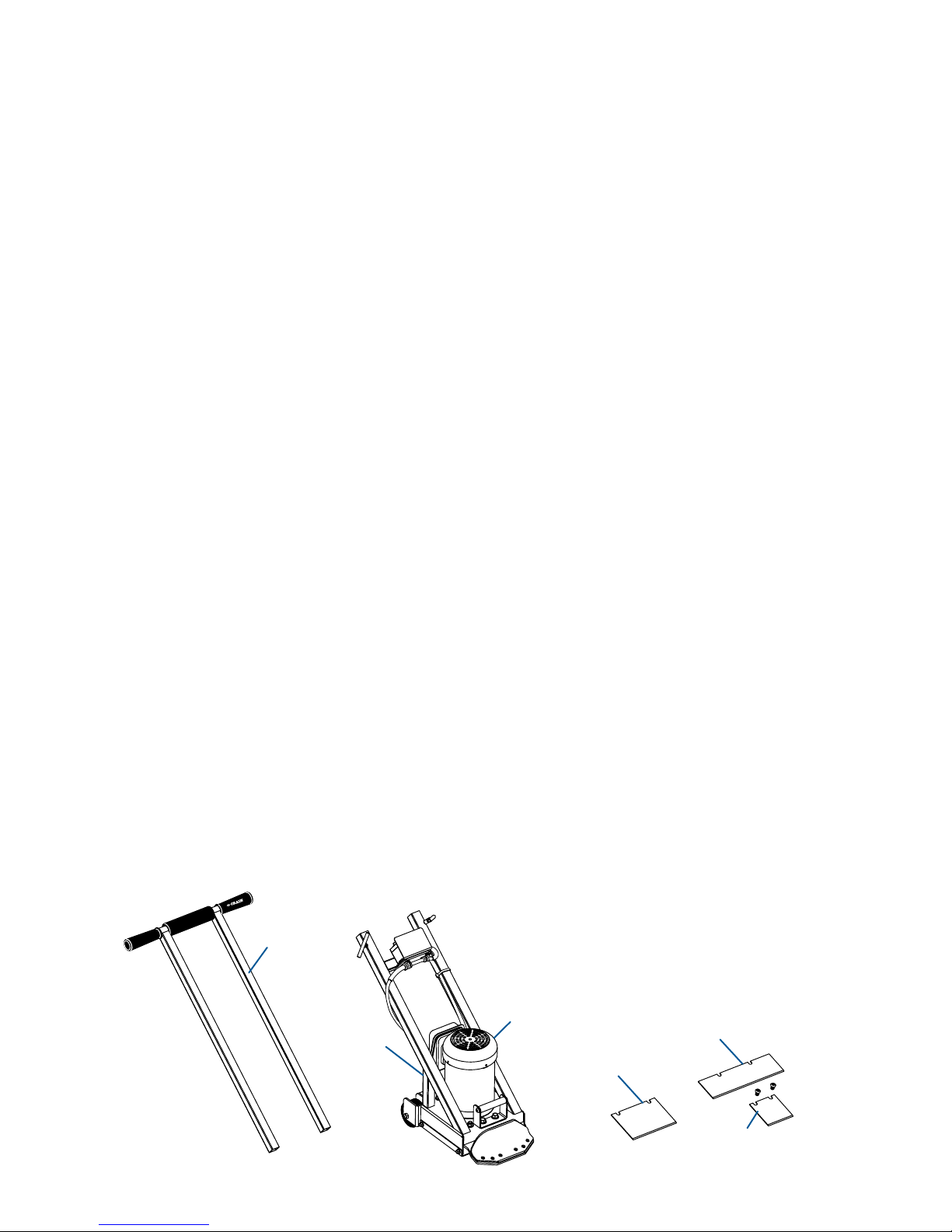
The Power Scraper comes complete with the following (see Figure 1):
� Motor
� Extendable Handle
� Vinyl, Multi-Purpose, and Spud Blades
EXTENDABLE
HANDLE
MOTOR
FAN COVER
No. 701
VINYL BLADE
No. 705
MULTI-PURPOSE
BLADE
No. 719
THIN SPUD
BLADE
MOTOR
Figure 1
Page 4
3
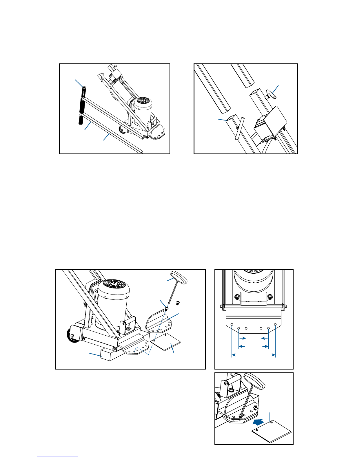
� Switch off and unplug the machine. A T-wrench is provided for loosening blade
screws (Figure 4).
� To change the blade, raise the blade carrier off the oor by placing a short piece
of wood beneath the machine to provide clearance (Figure 4). DO NOT lean the
machine back on its extendable handle for changing a blade, as this can result
in unexpected forward tipping or other unexpected motion.
� When the machine is in a stable and safe position, remove the blade screws
currently installed in the blade carrier, and remove the blade clamp.
� NOTE: Crain blades with slots can be changed
by loosening blade screws a few turns, pulling
out previous blade, then installing the new blade.
The blade screws and blade clamp do not need
to be fully removed.
INSTALLING AND CHANGING BLADES:
INNER
MIDDLE
OUTER
Figure 5
� The extendable handle (Figure 2) has two square extension tubes that insert into
the square tubes of the motor (Figure 3). Adjust to desired height, then tighten
the T-bolts in the square tubes. For starters, adjust handle to about waist height.
ASSEMBLING THE EXTENDABLE HANDLE:
Figure 2 Figure 3
SQUARE
TUBE
EXTENDABLE
HANDLE
MOTOR
FRAME
SQUARE
TUBES
T-BOLT
GRIP
Figure 4
T-WRENCH
BLADE
SCREWS
BLADE
CLAMP
No. 701
VINYL BLADE
WOOD
BLOCK
Figure 6
BLADE
SLOTS
Page 5

4
When stripping on concrete, install the blade with the bevel up. On wood oors,
or gibcrete or soft poured ooring, install the blade with the bevel down to reduce
unnecessary gouging or sticking of the blade into the oor. On soft wood suboors
(like particle board), it may be advisable to slightly dull the blades before use.
� The blade carrier has a number of holes for various blades (Figure 5 - see previous
page 3). See the table above for the proper holes to be used with each blade.
� For Crain blades with slots, slide the blade under the blade clamp until the blade
slots bottom on the blade screws. (For blades with holes, the blade screws, blade
clamp, and blade must be removed, then install the screws through the blade
holes.) Reassemble the blade clamp, blade and screws on the blade carrier.
� Tighten the blade clamp rmly with the proper blade screws fastened in the proper
holes prior to starting the machine.
ABOUT BLADE BEVEL: See Figures 8 and 9.
Figure 8
BEVEL UP
CONCRETE FLOORS
Figure 9
BEVEL DOWN
WOOD FLOORS
FASTENING BLADES:
Select a blade for the material you are stripping. See the table below for general
guidelines on blade usage. For each blade, the table also lists information about
the proper screw holes to be used on the blade carrier. The screw holes are shown
in Figure 5 (see previous page 3). To install the thin spud blade for tough take-up
jobs, use the two inner holes. For other blades, please reference the table below:
Item: Usage / Description: Edge: Holes:
701 4" x 6" Vinyl Single Middle
702D 4" x 6" D.E. Vinyl Double Middle
703 5" x 6" Carpet Single Middle
704D 5" x 6" D.E. Carpet Double Middle
705 3" x 10" Multi-Purpose Single Outer
706D 3" x 10" D.E. Multi-Purp. Double Outer
707 3" x 16" Wide Cleaner Single Outer
708 5" x 16" Wide Cleaner Single Outer
719 3½" x 3¾" Thin Spud Single Inner
In general, it is advisable to begin with narrower blades to determine the difculty
of the take-up job. If the material comes up easily, switching to wider blades can
take up wider sections of material. The wide 16" blades are “cleaner blades” mainly
used to remove residual adhesive only after the ooring material has been stripped.
SELECTING BLADE AND BLADE CARRIER HOLES:
Page 6
5
� Prior to using the machine, remove nails that may be present in the oor. Pre-slitting
carpet with a knife or a Crain No. 265 Stand-Up Cutter helps the machine remove
the material with less effort.
� Peel back an edge of the material to be stripped. A scraper (Crain No. 390) or a
pulling claw (Crain No. 844) in the case of carpet can be helpful.
� Check that the blade is fastened properly and that the blade screws, and extendable
handle T-bolts are tightened securely. Remove all wrenches or other tools attached
to the machine prior to starting.
� Grip machine at the vinyl grips of the extendable handle which provide electrical
insulation. Rubber gloves and rubber soled boots provide additional insulation.
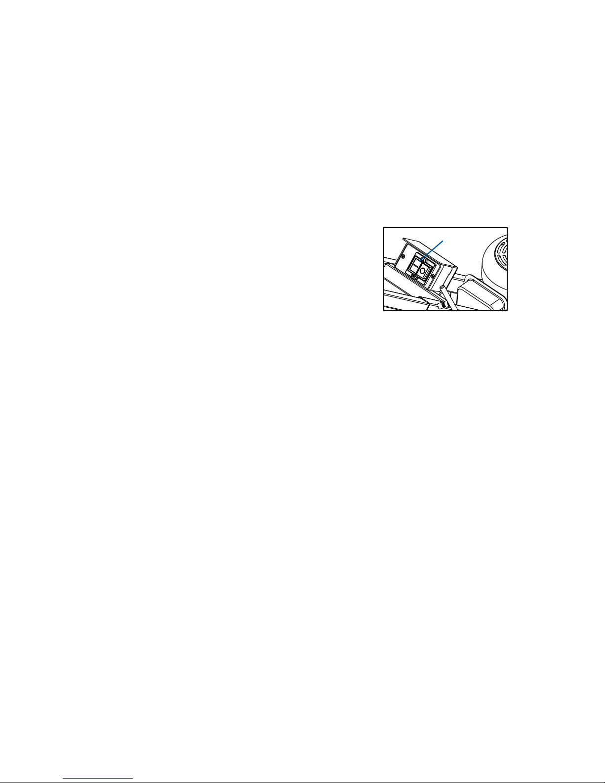
� Turn on the machine by depressing the green button
(Figure 10), and push the blade into the exposed edge
of the ooring to be stripped. It is best to push the
machine gradually and not to ram it into the material.
Ramming can damage the internal mechanisms and
void the warranty.
�
Do not force the machine. The machine works best moving forward at a controlled pace.
� Keep blades sharp. Machine performance depends on sharpness of blades.
� Keep clear from the sharp blade at all times. Keep feet and hands out from under
the machine.
� To stop the machine, back it away a short distance to disengage the blade from
the ooring being stripped. Press the red button to turn off power to the machine
(Figure 10). The machine will come to a stop shortly after it is turned off. Do not
leave the machine running unattended. Switch off machine after each operation.
USING THE MACHINE:
MAINTENANCE:
Figure 10
ON AND
OFF
BUTTONS
� Switch off and unplug the machine before performing any maintenance. Keep
water and other liquids out of the machine particularly the motor, switch, wiring,
and cords as this can cause an electrocution hazard. If the vinyl grips which
provide electrical insulation are lost or damaged, replace immediately (Part No.
1375-G). Keep oil and other liquids off the vinyl grips. Do not use the machine
if the switch becomes damaged or non-operational. Switch damage can cause
the machine to not switch off. Do not use the machine if the cord, plug, or other
wiring is cut or damaged. Do not use the machine without the protective fan cover
or bottom cover in place. Keep dust and debris away from vents and openings.
� If abnormal noise or vibration occurs, switch off and unplug machine and have
it repaired before further use. If the machine is dropped, the blade carrier (Part
No. 1718-12) or blade clamp (Part No. 1718-16) can be bent or damaged. Do
not use the machine until these parts have been repaired.
� Do not use the machine if it is damaged. Do not attempt to dis-assemble or re-
wire the machine. Repairs should be performed by factory authorized service
personnel or an electrician.
Page 7

6
REPLACEMENT PARTS, GUARANTEE AND APPENDIX:
SEE PAGES 7-10.
� Use new, sharp blades with your machine. Failure to do so results in poor per-
formance or machine kick-back.
Page 8
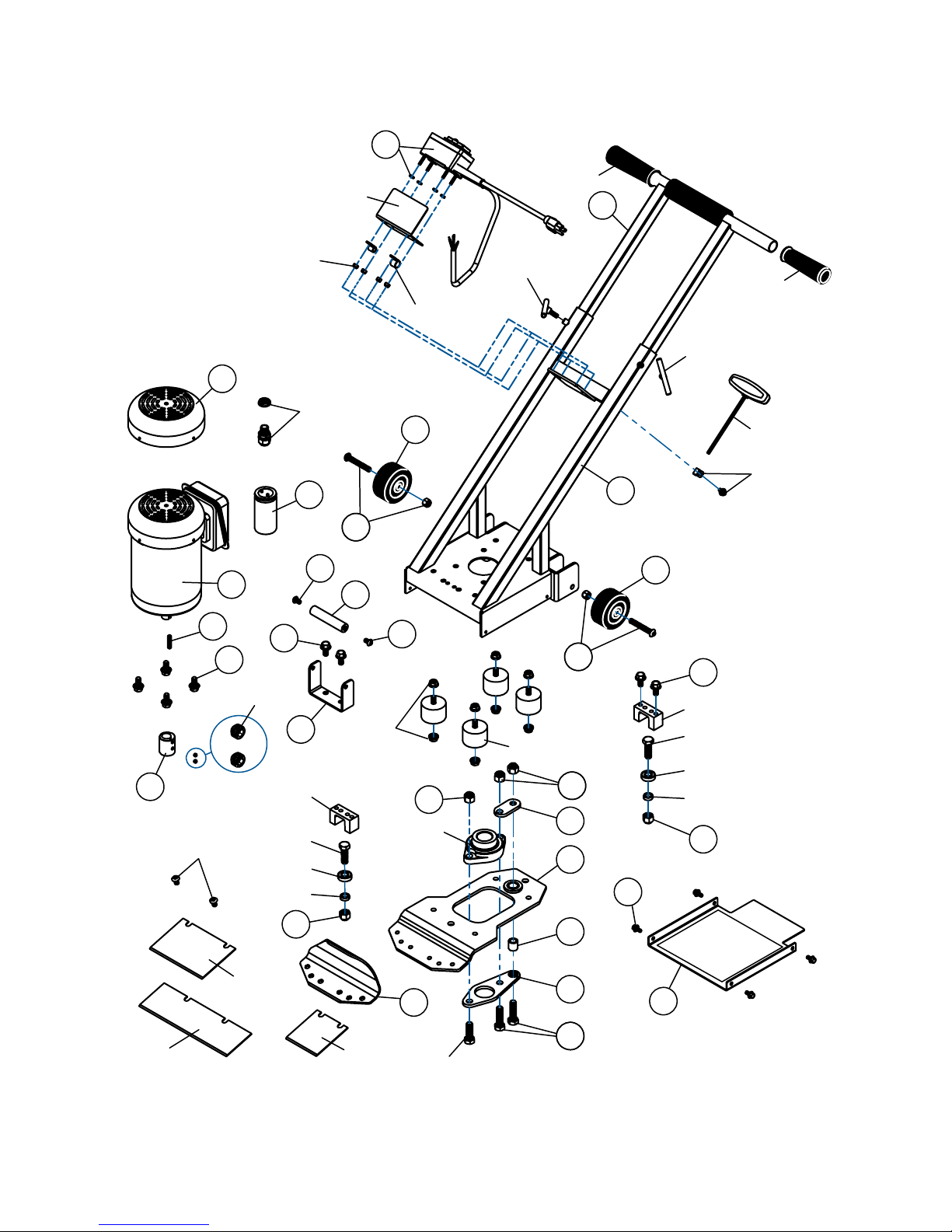
7
REPLACEMENT PARTS DIAGRAM
1710-13
1710-48
1710-57
10
1710-37
12
13
14
15
16
17
18
20
20
2121
2121
23
25
24
1375-G
1375-G
1710-29
1710-29
1710-47
1710-681710-68
1710-83
1710-84
1710-85
1710-811710-81
30
701
705
719
30
30
19
19
1710-13
11
35
1710-53
1710-53
1710-36
1710-36
1710-37
31
34
31
31
1710-64
1710-15
3232
1710-53
26
27
1710-24
31
31
29
Page 9

8
WARNING: This machine produces dust and peelings. Observe the following:
WARNING: Extreme care should be taken when stripping paint. The peeling, resi-
due and vapors of paint may contain lead, which is poisonous. Any pre-1977 paint
may contain lead and paint applied to homes prior to 1950 is likely to contain lead.
Once deposited on surfaces, hand to mouth contact can result in the ingestion of
lead. Exposure to even low levels of lead can cause irreversible brain and nervous
system damage; young and unborn children are particularly vulnerable.
Before beginning any paint removal process you should determine whether the paint
you are removing contains lead. This can be done by your local health department
or by a professional who uses a paint analyzer to check the lead content of the
paint to be removed. LEAD-BASED PAINT SHOULD ONLY BE REMOVED BY A
PROFESSIONAL AND SHOULD NOT BE REMOVED USING A HEAT GUN.
REPLACEMENT PARTS:
APPENDIX: IMPORTANT SAFETY INSTRUCTIONS - READ THESE INSTRUCTIONS!
Order No. Description
1718-10 Main Body
1718-11 Extendable Handle & Grips
1718-12 Blade Carrier
1718-13 Bottom Cover & Foil
1718-14 Motor 1/2 HP 120V
1718-15 Eccentric & Screws (2)
1718-16 Blade Clamp
1718-17 Handle Bracket
1718-18 Handle
1718-19 Handle Screws Only (2)
1718-20 3" Poly Wheel
1718-21 Wheel Bolt & Nut (2)
1718-23 Spindle Key
1718-24 Motor Fan Cover & Screws
1718-25 Motor Capacitor
1718-26 Pivot Plate
1718-27 Connector
1718-29 Spacer
1718-30 Motor & Guide Channel
Screws (4)
1718-31 Pivot Plate & Guide Channel
Lock Nuts (2)
Order No. Description
1718-32 Pivot Plate Screws (2)
1718-34 Cover Screws (4)
1718-35 Cord, Switch & Mounting Screws
1710-13 Guide Channel
1710-15 Rubber Damper
1710-24 Bearing Block
1710-29 Short T-Bolt
1710-36 Ball Bearing
1710-37 Bearing Spacer
1710-47 T-Handle Wrench
1710-48 Eccentric Screws Only (2)
1710-53 Bearing Screw
1710-57 Blade Clamp Screw (Short - 2)
1710-64 Rubber Damper Hex Lock Nut Set (2)
1710-68 T-Handle Wrench Holder & Screw
1710-81 Motor Cable Connector
1710-83 Switch Shield Plate
1710-84 Loop Clamp Set (2)
1710-85 Switchbox Nuts Set (4)
1375-G Handle Grip Only
Persons removing paint should follow these guidelines:
1. Move the work outdoors. If this is not possible, keep the work area well venti-
lated. Open the windows and put an exhaust fan in one of them. Be sure the fan
is moving the air from inside to outside.
2. Remove or cover any carpets, rugs, furniture, clothing, cooking utensils and air ducts.
3. Place drop cloths in the work area to catch any paint chips or peelings. Wear
protective clothing such as extra work shirts, overalls and hats.
4. Work in one room at a time. Furnishings should be removed or placed in the
center of the room and covered. Work areas should be sealed off from the rest of
the dwelling by sealing doorways with drop cloths.
5. Children, pregnant or potentially pregnant women, and nursing mothers should
not be present in the work area until the work is done and all clean-up is complete.
6. Wear a dust respirator mask or a dual lter (dust and fume) respirator mask which
Page 10

9
has been approved by the Occupational Safety and Health Administration (OSHA),
the National Institute of Safety and Health (NIOSH), or the United States Bureau of
Mines. These masks and replaceable lters are readily available at major hardware
stores. Be sure the mask ts. Beards and facial hair may keep masks from sealing
properly. Change lter often. DISPOSABLE PAPER MASKS ARE NOT ADEQUATE.
7.
Keep food and drink out of the work area. Wash hands, arms and face and rinse
mouth before eating or drinking. Do not smoke, or chew gum or tobacco in the work area.
8. Clean-up all removed paint and dust by wet-mopping the oors. Use wet cloth to
clean all walls, sills, and other surface where paint or dust is clinging. DO NOT SWEEP,
DRY DUST OR VACUUM. Use a high phosphate detergent or trisodium phosphate
(TSP) to wash and mop areas.
9. At the end of each work session put the paint chips and debris in a double plastic
bag, close it with tape or twist ties, and dispose of properly.
10. Remove protective clothing and work shoes in the work area to avoid carrying
dust in to the rest of the dwelling. Wash work clothes separately. Wipe shoes off with
wet rag that is then washed with the work clothes; wash hair and body thoroughly
with soap and water.
WARNING: Some dust created by power sanding, sawing, grinding, drilling, and other
construction activities contains chemicals known to the State of California to cause cancer, birth defects or other reproductive harm. Some examples of these chemicals are:
• lead from lead-based paints,
• crystalline silica from brick, cement and other masonry products, and
• arsenic and chromium from chemically-treated lumber.
Your risk from these exposures varies, depending on how often you do this type of work.
To reduce your exposure to these chemicals: work in a well-ventilated area, and work with
approved safety equipment, such as those dust masks that are specially designed to lter
out microscopic particles.
WARNING: Some ooring to be removed like carpet which originally did not contain
asbestos, lead-based paint or other hazardous materials may become contaminated
by deposits of asbestos bers, peelings from lead-based paint, or other hazardous
materials. Removing the carpet could result in these materials being ingested. Any
contaminated product should be removed by an accredited abatement professional.
WARNING: Grinding, cutting, or drilling of masonry, concrete, metal and other materials
with silica in their composition may give off dust or mists containing crystalline silica.
Silica is a basic component of sand, quartz, brick clay, granite and numerous other
minerals and rocks. Repeated and/or substantial inhalation of airborne crystalline
silica can cause serious or fatal respiratory diseases, including silicosis.
WARNING: This product can expose you to chemicals including acrylonitrile, asbestos, carbon black, ceramic bers, chromium (hexavalent compounds), cobalt metal
powder, di(2-ethylhexyl)phthalate (DEHP), diisononyl phthalate (DINP), lead and lead
compounds, nickel (metallic), nickel acetate, silica, crystalline, styrene, urethane, vinyl
chloride, and wood dust which are known to the State of California to cause cancer,
and bisphenol A (BPA), cadmium, chromium (hexavalent compounds), di(2-ethylhexyl)
phthalate (DEHP), di-isodecyl phthalate (DIDP), lead, toluene and urethane which are
known to the State of California to cause birth defects or other reproductive harm.
For more information go to www.P65Warnings.ca.gov/product.
Page 11
CRAIN
GUARANTEE
This No. 718 Power Scraper is guaranteed to be free of de-
fects in workmanship or quality of materials for a period of
ONE YEAR.
Any parts of tools found defective subject to the guarantee
will be replaced at no charge. Credit in full or part cannot be
extended by the distributor. New tools will not be given as
replacements for those pending a warranty adjustment.
All merchandise returned subject to this warranty must be
accompanied with same. All merchandise returned must be
F.O.B. Milpitas, California, and must be in complete assembled
units. No consideration will be given to unassembled parts. All
disputes will be up to the consideration of the CRAIN CUTTER
CO., INC. and their decision will be nal.
Please ll out and mail this card to validate
your CRAIN guarantee.
NAME
ADDRESS
CITY
STATE ZIP
TOOL PURCHASED:
No. 718 Power Scraper
PURCHASED FROM:
DATE PURCHASED:
PLEASE CHECK:
INDIVIDUAL FLOORING INSTALLER
WORKROOM
FLOORING DEALER
INSTALLATION CONTRACTOR
OTHER
❑
❑
❑
❑
❑
Page 12

Crain Cutter Co., Inc.
1155 Wrigley Way
Milpitas, CA 95035-5426
PLACE
STAMP
HERE
Printed by: HF FORM F1718 2019-01
 Loading...