

Page 1
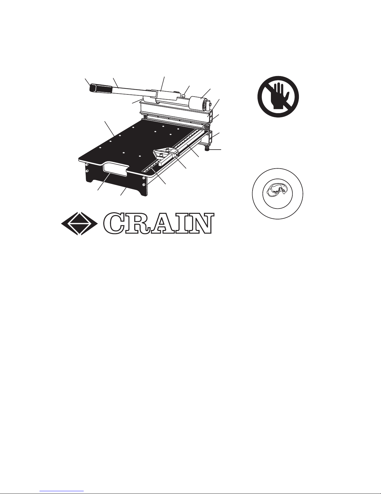
NO. 673 13" WOOD CUTTER
SAFETY FIRST:
The Crain 13" Wood Cutter is designed to cut wood and laminate ooring
planks only. It is not designed for cutting shingles or wall siding. Do not use
this cutter for any purpose not described in this manual. Read and save all
instructions.
This cutter has a sharp blade. Keep hands away! The blade is lever-activated
and can cause severe cuts or sever ngers or hands. Pay attention to the
position and motion of the blade in operation and transportation of the cutter.
If the material being cut gets stuck on the blade, remove the stuck material
from the blade using scrap material or other tool. Do not use bare hands!
Keep hands away from the blade at all times. Use of new, clean, sharp blades
can reduce the sticking of materials on the blade.
Scrap materials, dust, and splinters can accumulate around the blade, behind
the blade, or on the bed of the cutter. These can impair the safe operation of
the cutter. Keep these clear at all times by dusting them off using a piece of
scrap material or other tool. Keep hands away from the blade.
The cutting operation may leave splinters or sharp edges on the material that
INSTRUCTIONS FOR
Carrying
Handle
Ruler
Cut Guide
Fence
Bottom
Bar
Guide
Post
Blade
Pressure
Roller
Blade
Carrier
Safety
Lock
Connector
Tube
Pressure
Roller
Leverage
Handle
Grip
Bed
Rear
Stand
T
h
i
n
k
S
a
f
e
t
y
W
e
a
r
E
y
e
P
r
o
t
e
c
t
i
o
n
CRAIN
KEEP HANDS
AWAY FROM:
WARNING!
BLADE
BLADE CARRIER
PRESSURE ROLLERS
Figure 1
Page 2
2
is being cut. Some materials may require sanding before nal installation.
Inspect all cuts prior to installation. Do not install cut pieces with splinters
or sharp edges. Keep splinters and cut pieces with sharp edges out of the
work area.
This cutter has two pressure rollers that can pinch and crush ngers or hands.
Keep hands away!
Keep ngers and hands out from underneath the blade carrier, as these can
be crushed against the material being cut, or against the bed of the cutter.
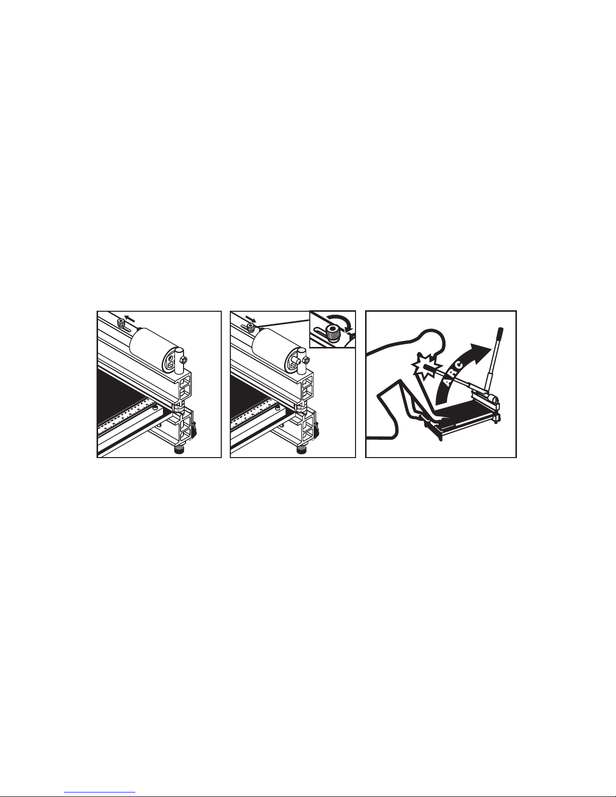
The cutter has a safety lock that holds the leverage handle and the blade in
the down position. For protection, lock the safety lock whenever the cutter is
not in use. Also, lock the safety lock whenever the cutter is being transported
or placed in storage. To lock the safety lock, move the handle to the down
position, then slide the safety lock to the far right (Figure 3). When the safety
lock is locked, tighten the safety lock’s lock nut to x the safety lock in locked
position.
This cutter has a spring-loaded leverage handle that rises automatically with
enough force to cause injury (Figure 4). Be aware of the motion of the leverage handle. As it rises, guide the leverage handle to its starting upright position to prevent it from slamming against its stop or impacting your body. In
operation, kneel to the side of the leverage handle, keeping your head and the
rest of the body out of its arc, and keep bystanders out of the way.
Wear eye and ear protection when using this cutter.
This cutter is not to be used by children or persons with reduced physical,
sensory or mental ability, or that lack experience and knowledge, unless they
have been given supervision or instruction.
Keep the work area clean. Clutter invites accidents. The work environment
should be clean, dry, well lit, and clear of any ammable materials or explosive gasses. Do not use the cutter in wet or damp conditions.
Keep children and bystanders away from the cutter and out of the work area.
LOCK
NUT
Figure 2 - Unlocked Figure 3 - Locked Figure 4
Page 3

3
This cutter is a ooring tool for use on the oor only. It has a spring-loaded
leverage handle that generates a lot of force and can cause motion such as
tipping of the cutter. Do not use the tool on a table that can tip and cause
the cutter to fall, or anywhere near stairs or balconies from which it may fall.
Keep blades clean and sharp. Dull blades can require excessive cutting force,
which may result in increased risk of injury, or damage to the tool.
CAUTION: Do not apply excessive force to the cutter, as this can cause injuries, including back injuries, and can damage the cutter. Do not alter the cutter by using attachments such as extended leverage handles or other power
sources. Damage or injury may result. Use only Crain replacement blades
designed for use with this cutter.
Some dust created by cutting contains chemicals that can be injurious to
your health, including formaldehyde. Work in a well-ventilated area, and work
with approved safety equipment. If necessary, wear a dust respirator mask or
a dual lter (dust and fume) respirator mask which has been approved by the
Occupational Safety and Health Administration (OSHA), the National Institute
of Safety and Health (NIOSH), or the United States Bureau of Mines. These
masks and replaceable lters are readily available at major hardware stores.
Be sure the mask ts. Beards and facial hair may keep masks from sealing
properly. Change lter often. Disposable paper masks are NOT adequate.
CAUTION: Tool is heavy! Users with adequate strength should move the cutter with proper lifting technique and constant awareness of the sharp blade.
Be careful not to drop the machine on feet or other body parts. Carry the
cutter by its carrying handle (Figure 1). Do not carry the cutter by the leverage
handle, the blade carrier, or bottom bar. Keep hands away from the blade!
Store the cutter out of reach of children, with the safety lock in the locked
position (Figure 3). Store the cutter in a safe location that prevents the cutter
from falling and causing possible injury.
OPERATION:
MATERIALS THAT CAN BE CUT: This cutter is designed to cut wood and
laminate plank oor materials up to ¾" thick one plank at a time.
Some of these materials may require excessive force to be cut, resulting in
possible damage to the cutter, or injury to the user. This depends on the
hardness of the material, grain structure, thickness of the laminate or other
wear layer (veneer), the width of the board, or a combination of these factors.
In general, if the leverage handle develops signicant bend and the blade is
not cutting through the material, the cutter should not be used on that material. WARNING: do not attempt to cut materials that require excessive force.
Injuries including back injury may occur. Damage to the leverage handle
voids the cutter warranty!
Page 4
4
In general, materials harder than red oak (Janka hardness of 1290), including
white oak, most species of maple, cherry, mahogany, bamboo, hickory, pecan
and most exotic hardwoods should not be cut with this cutter. Janka hardness ratings for most woods are available on the Internet. Laminate ooring
with a high pressure wear layer should not be cut with the cutter. Engineered
hardwood ooring with a wear layer greater than 2 mm should not be cut with
the cutter. Cutting excessively hard material chips and damages blades.
PREPARING TO CUT: Place the cutter at on the oor with its two guide
posts and rear stand at on the oor. In use, the cutter must be stable on the
oor and prevented from rocking or tipping. Make sure there is space around
the cutter for handle travel (Figure 4). Check that the blade is sharp and free
of burrs (for instructions on removing burrs, see MAINTENANCE below).
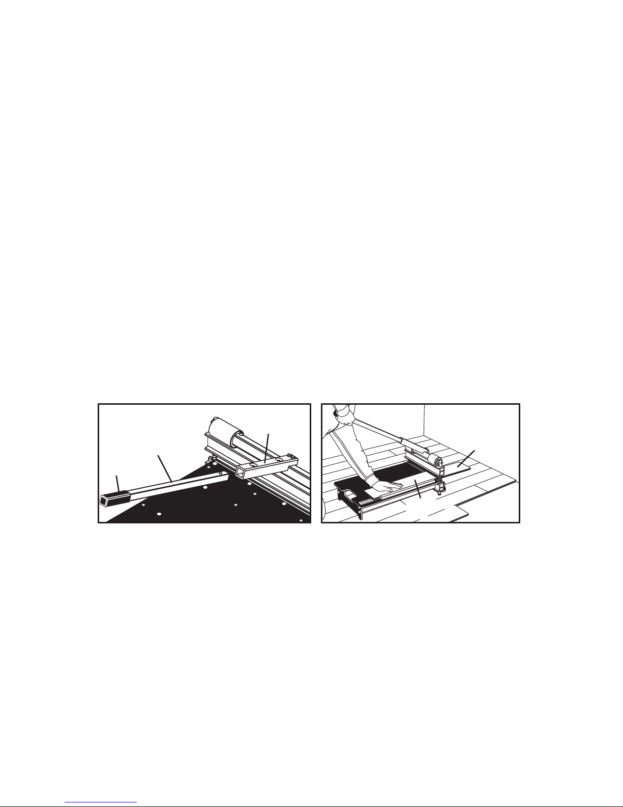
ASSEMBLE THE LEVERAGE HANDLE: This cutter is designed to be powered manually using the leverage handle that is provided. Do not add additional leverage handles or other power sources to the cutter.
To assemble the leverage handle, insert it into the connector tube on the
blade carrier (Figure 5). The leverage handle includes a spring-loaded button
that engages one of the two holes in the connector tube. In normal operation,
the leverage handle is engaged in the upper hole for increased leverage. In
transportation or storage, slide the leverage handle inward and engage the
button in the lower hole.
DISENGAGING THE SAFETY LOCK: Grasp the leverage handle at the grip
to control its motion. Loosen the safety lock’s lock nut, then slide the safety
lock all the way to the left to disengage (Figure 2). Tighten the safety lock’s
lock nut to hold it in the disengaged position. The leverage handle is spring
loaded and will rise automatically. In operation, keep a hand on the grip of
the leverage handle to keep it under control.
MAKING CUTS: Place the material to be cut on the bed of the cutter and
slide it against the fence (see below and Figure 7) and beneath the blade.
Keep hands away from the blade and out from under the blade carrier. Note
that the blade produces the cleanest edge from its inner (bed facing) edge
surface only. The cut piece remaining on the bed will be the nished cut, and
the piece beyond the blade will be scrap (Figure 6).
To assist in producing the desired length of cut, the bed of the cutter includes
LEVERAGE
HANDLE
GRIP
CONNECTOR
TUBE
Figure 5 Figure 6
SCRAP
FINISHED
CUT
Page 5
5
a ruler in both inches and metric units. The ruler measures the distance from
the inner edge surface of the blade, indicating the length of nished cut.
Push down on the leverage handle with one hand, keeping the other hand on
top of the material being cut. HAND PRESSURE should be used to power
the cutter, not foot pressure, body weight, other weight, or impact on the leverage handle. Keeping a hand on the material prevents it from moving and
ensures an accurate cut. Keep hands away from the blade, blade carrier, and
pressure rollers at all times, and keep hands out from under the material being cut. Stay alert and watch the cutting process at all times. (See Figure 6.)
Continue pushing the leverage handle until the material is cut, then raise it
with a hand on the grip and the assistance of the springs. Do not allow the
handle to rise rapidly and slam against the stop. Injury or damage may result.
After the cut, the material being cut may become stuck on the blade. Remove the stuck material from the blade using scrap material or other tool. Do
not use bare hands!
Prevent build-up of scrap, splinters and dust around the blade, blade carrier,
and on the cutting bed. Dust off using a piece of scrap or other tool.
Check the cut edges of any material that will be installed for splinters or sharp
edges. These may require removal by sanding or trimming to prevent injury.
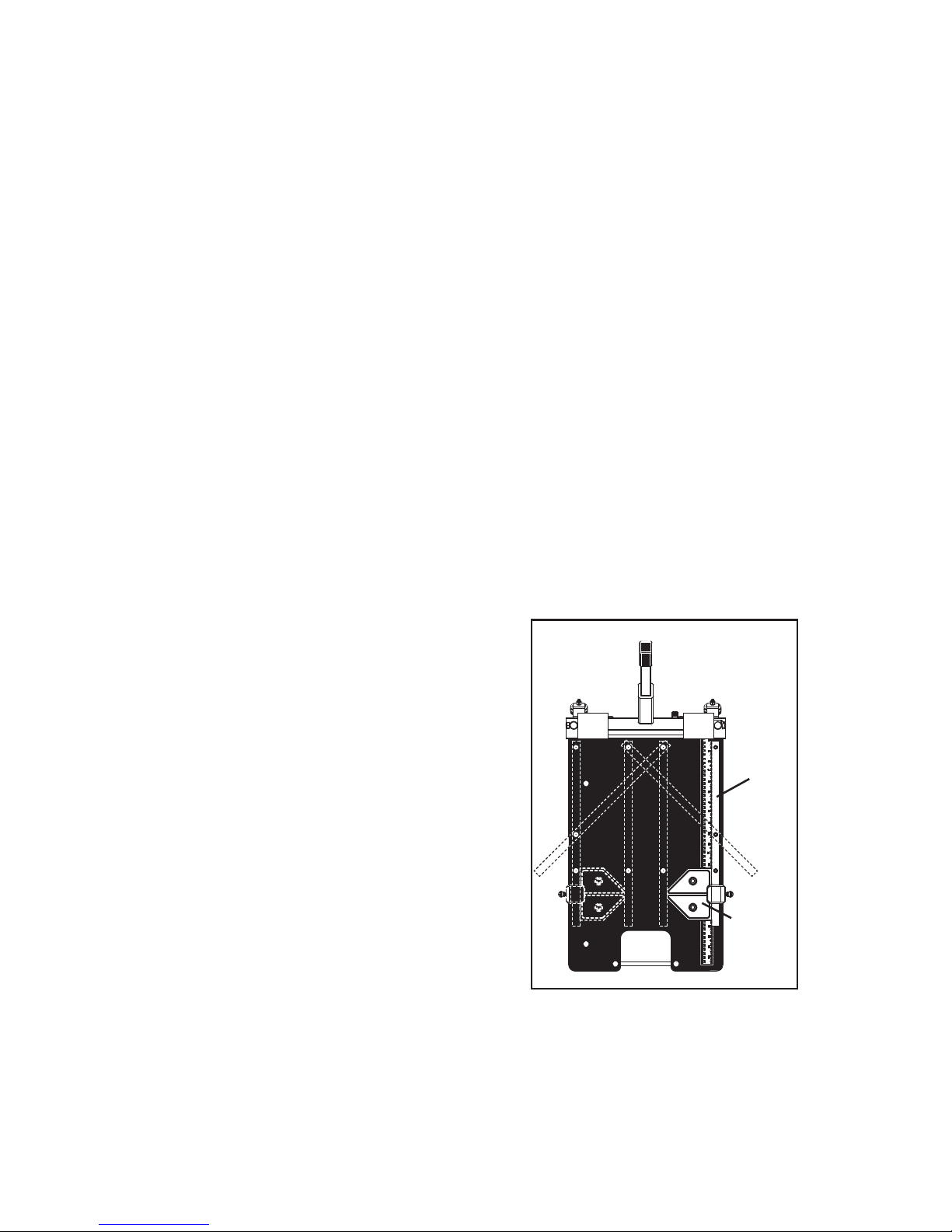
The fence of the cutter is movable to any
one of four straight positions, or one of two
45° angle positions (Figure 7). Moving the
fence helps position the material being cut
under different areas of the blade, so that
as areas of the blade become dull, other
areas that are still sharp can be more easily used. Cutting under different areas of
the blade also wears the sides of the cutter
mechanism more evenly over time, extending the life of the tool. Cutting mostly under
one side can wear out the cutter sooner.
To move the fence, remove the two wing
nuts from beneath the bed, and remove
the fence. Insert the fence into any pair of
holes as shown in Figure 7, then reattach
and tighten the wing nuts.
The cutter comes with a cut guide that attaches to the fence using a wing
screw (Figure 7). The cut guide can be used to set a length of cut for repeating a length of cut. If the fence is moved to the left or right, the cut guide can
be moved onto either side of the fence. The cut guide includes a 45° angle.
Figure 7
CUT
GUIDE
FENCE
Page 6
6
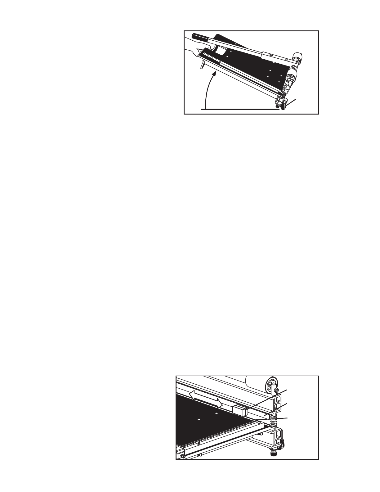
The cutter includes wheels for
moving the cutter easily from a
kneeling position (Figure 8). Simply lift the back of the bed off the
oor to about a 30° angle, and the
wheels will contact the oor for
wheeling the cutter from place to
place without having to get up and
carry it by the carrying handle.
TRANSPORTATION AND STORAGE:
Whenever the tool is left unattended, or during transportation or storage, the
safety lock should be locked (Figure 3). The safety lock lowers the blade
to shield it from contact, and prevents unexpected motion of the leverage
handle. To lock the safety lock, lower the leverage handle to its bottom position and slide the safety lock all the way to the right. The safety lock includes
a lock nut that should be tightened down to prevent accidental unlocking.
For transportation or storage, the leverage handle should also be positioned
with its button in the lower hole of the connector tube.
Carry the cutter by its carrying handle (Figure 1). Do not carry the cutter using
its leverage handle, blade carrier, or bottom bar. Keep hands away from the
blade, blade carrier, and pressure rollers at all times.
When transporting or storing the cutter, use caution to prevent the cutter from
being dropped or falling. Damage to the cutter or injury may result.
In transportation or storage, do not pile heavy materials on top of the tool
such as by putting it in the bottom of the van and piling up ooring and other
materials on top of it. Damage to the cutter’s bed and mechanism may result.
MAINTENANCE:
BURRS OR NICKS ON BLADE: Burrs or nicks may develop on the inner
(bed facing) side of the blade that can cause the blade to seem dull and
cut less efciently. The cutter
includes a sharpening stone
that can be used for restoring
the edge as much as possible
(Figure 9). There is no need to
remove the blade from the blade
carrier. Simply raise the leverage handle to raise the blade
enough distance for adequate
clearance of the stone, then lay
LIFT BACK
OF BED 30º
WHEELS
STONE
BLADE
ANVIL
Figure 8
Figure 9
Page 7
7
the wide side of the stone against the inner face of the blade. NOTE - the
stone is two-sided: coarse and ne. Use the coarse side for large burrs or
nicks, and the ne side for smaller ones. Move the stone back and forth from
end to end of the blade. Use caution not to rub the anvil of the cutter with the
stone, or undue wear may result. The stone should contact the blade only.
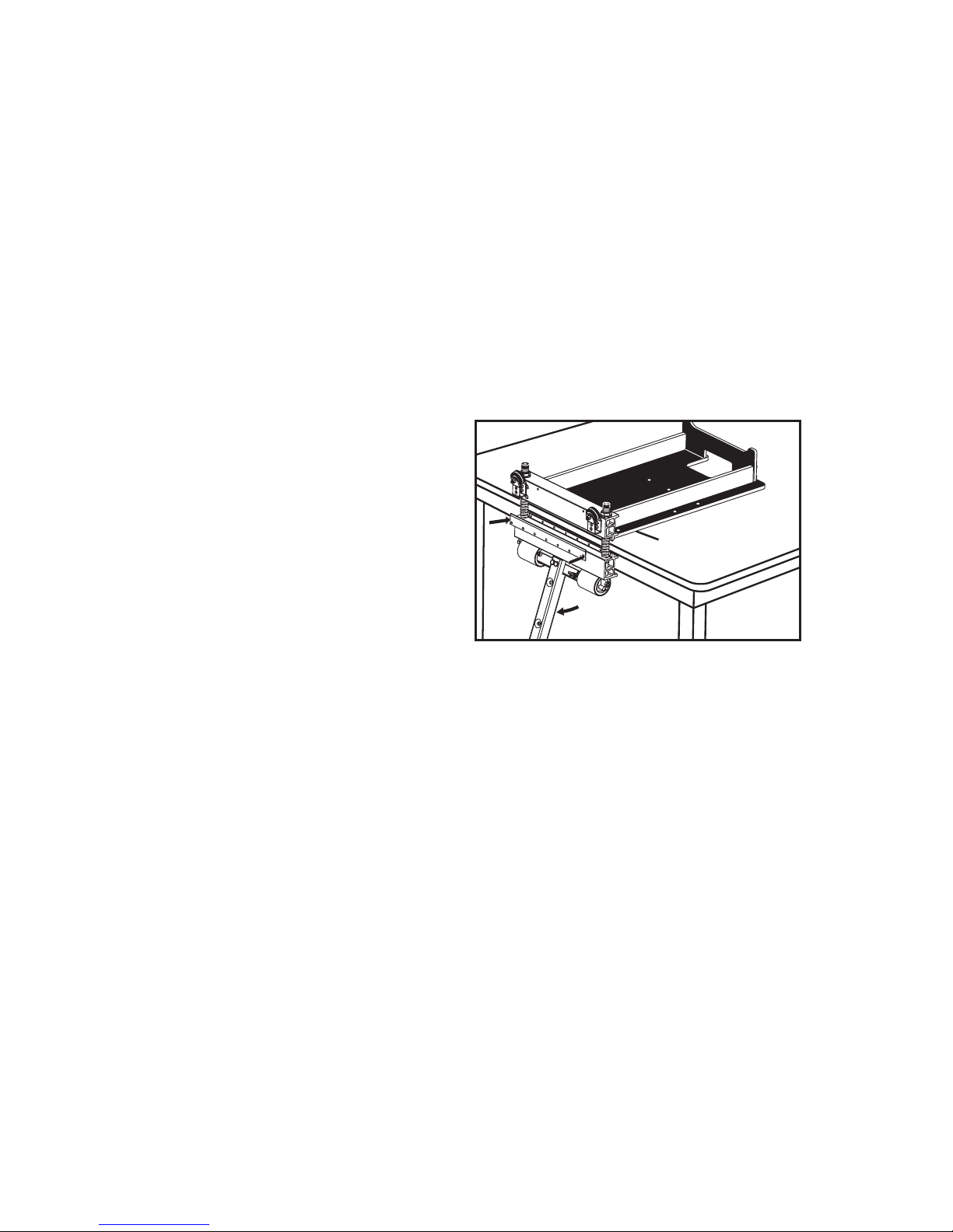
CHANGING THE BLADE - WARNING: The blade is extremely sharp, and it
can be slippery and difcult to hold. Use extreme caution! The use of gloves
is recommended. To remove and replace the blade, rst remove the leverage
handle, fence, and cut guide. Turn the cutter upside down and place the bed
at on a large, stable surface such as a solid table that will not tip or move
(Figure 10). Turning the cutter upside down ensures the blade will rest on the
blade carrier during the process due to gravity, and prevents the blade from
unexpectedly falling off. Move the connector tube to the top of its travel. This
increases the space between the blade and the anvil and provides more room
to work.
Remove the 7 blade screws using a
Phillips screwdriver. Hold the blade
against the blade carrier when removing the last screws by contacting a at surface of the blade body
away from the sharpened edge.
When removing a blade or installing
a new blade, it is advisable to hold it
by its sides.
When installing a new blade, it must be installed with the edge up and the
bevel out in relation to the bed. Be sure the blade carrier is cleared of all debris before installing the blade. Fasten the blade to the carrier with the seven
blade screws.
WARNING: Some dust created by power sanding, sawing, grinding, drilling,
and other construction activities contains chemicals known to the State of
California to cause cancer, birth defects or other reproductive harm. Some
examples of these chemicals are:
rMFBEGSPNMFBECBTFEQBJOUT
rDSZTUBMMJOFTJMJDBGSPNCSJDLDFNFOUBOEPUIFSNBTPOSZQSPEVDUTBOE
rBSTFOJDBOEDISPNJVNGSPNDIFNJDBMMZUSFBUFEMVNCFS
Your risk from these exposures varies, depending on how often you do this
type of work. To reduce your exposure to these chemicals: work in a wellventilated area, and work with approved safety equipment, such as those
dust masks that are specially designed to lter out microscopic particles.
CONNECTOR
TUBE AT TOP
OF TRAVEL
Figure 10
REMOVE
FENCE SO BED
RESTS FLAT ON
TABLE
Page 8
12
1675-32
674
1675-13
1675-14
1675-15
1675-18
1675-19
1675-20
1675-31
1675-45
1675-46
1675-22
1675-28
1675-25
1675-41
1675-24
1555-O
1675-38
1675-39
1675-40
1675-33
1675-27
1675-37
1675-47
1675-34
1675-35
1675-30
11
10
13
15
16
14
17
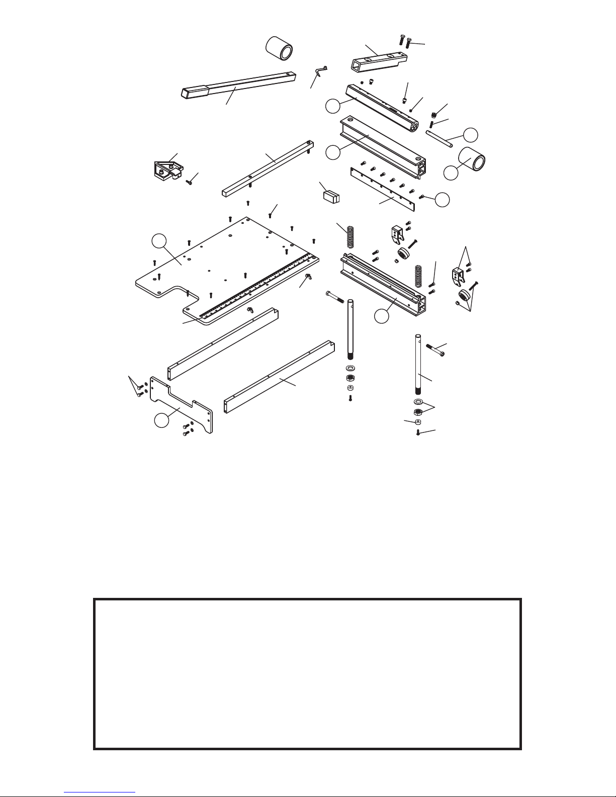
Order # Description
1673-10 Bottom Bar
1673-11 Blade Carrier
1673-12 Crankshaft
1673-13 Bed
1673-14 Pressure Roller (1 only)
1673-15 Rear Stand
1673-16 Safety Lock Bar
1673-17 Blade Screw Set (7)
674 13" Wood Cutter Blade
Parts common to the No. 675
1675-13 Bed Support (1 only)
1675-14 Connector Tube
1675-15 Leverage Handle
1675-18 Fence
1675-19 Ruler Label
1675-20 Guide Rod (1 only)
1675-22 Compression Spring Set (2)
1675-24 Safety Lock Thumb Screw
1675-25 Spring Clip
1675-27 Wheel Bracket (1) & Fast. (2)
1675-28 Blade Sharpening Stone
1675-30 Cut Guide
1675-31 Adjustment Nut & Washer
1675-32 Fence Wing Screw Set (2)
1675-33 Roller Wheel & Fasteners (2)
1675-34 Bed Fastener Set (13)
1675-35 Cut Guide Thumb Screw
1675-37 Bed Support Fasteners (2)
1675-38 Crankshaft Set Screws (2)
1675-39 Pressure Roller Set Screws (2)
1675-40 Connector Tube Screws (2)
1675-41 Crankshaft Pivot Bolts (2)
1675-45 Guide Rod Foot (1)
1675-46 Guide Rod Foot Screw (1)
1675-47 Rear Stand Fasteners (4)
1555-O Set Screw (Safety Lock Bar)
GUARANTEE
This No. 673 13" Wood Cutter is guaranteed to be free of defects in workmanship or quality of materials for a period of ONE YEAR. Any parts of tools found
defective subject to the guarantee will be provided at no charge. Credit in full or
part cannot be extended by the distributor. New tools will not be given as replacements for those pending a warranty adjustment. All merchandise returned subject
to this warranty must be accompanied with same. All merchandise returned must
be shipped freight prepaid to CRAIN CUTTER CO., INC. (“Crain”), and must be in
complete assembled units. No consideration will be given to unassembled parts.
All disputes will be up to the consideration of Crain and their decision will be nal.
REPLACEMENT
PARTS:
$3"*/500-4r8SJHMFZ8BZr.JMQJUBT$"r
 Loading...