

Page 1
GUARANTEE
INSTRUCTION
MANUAL
No. 265
STAND-UP CUTTER
WARNING: SHOCK HAZARD!
AVOID POWER LINES. CHECK
FOR CONCEALED ELECTRICAL
WIRING. KEEP TOOL 10 FEET
FROM ALL ELECTRIC LINES.
Printed by: HF Form 1265-Rev. 03/2012
Milpitas, CA 95035
TELEPHONE (408) 946-6100
CRAIN CUTTER CO., INC.
This Crain No. 265 Stand-Up Cutter is guaranteed
to be free of defects in workmanship and quality of
materials for a period of 90 days.
Any parts found defective subject to the guarantee
will be replaced at no charge. Credit in full or part
cannot be extended by the distributor, nor will a new
tool be given as a replacement or loaner.
Tools subject to this warranty must be accompanied by the same, and returned freight PREPAID to
Milpitas, CA, and must be in assembled condition.
REPLACEMENT PARTS:
ORDER NO. DESCRIPTION
266 Replacement Point
1265-A2 Blade Clamp
No. 265
Page 2
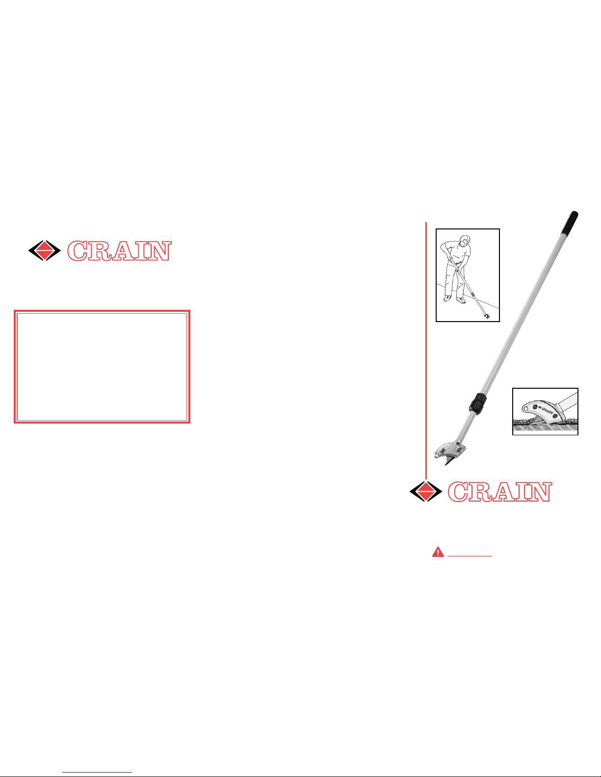
The Stand-Up Cutter is used for cutting gluedown carpet into small strips for easy removal. Its
versatile blade holder takes either utility blades or
hook blades. Its unique handle features a doublelocking mechanism for safety.
INTRODUCTION
BLADE INSTALLATION
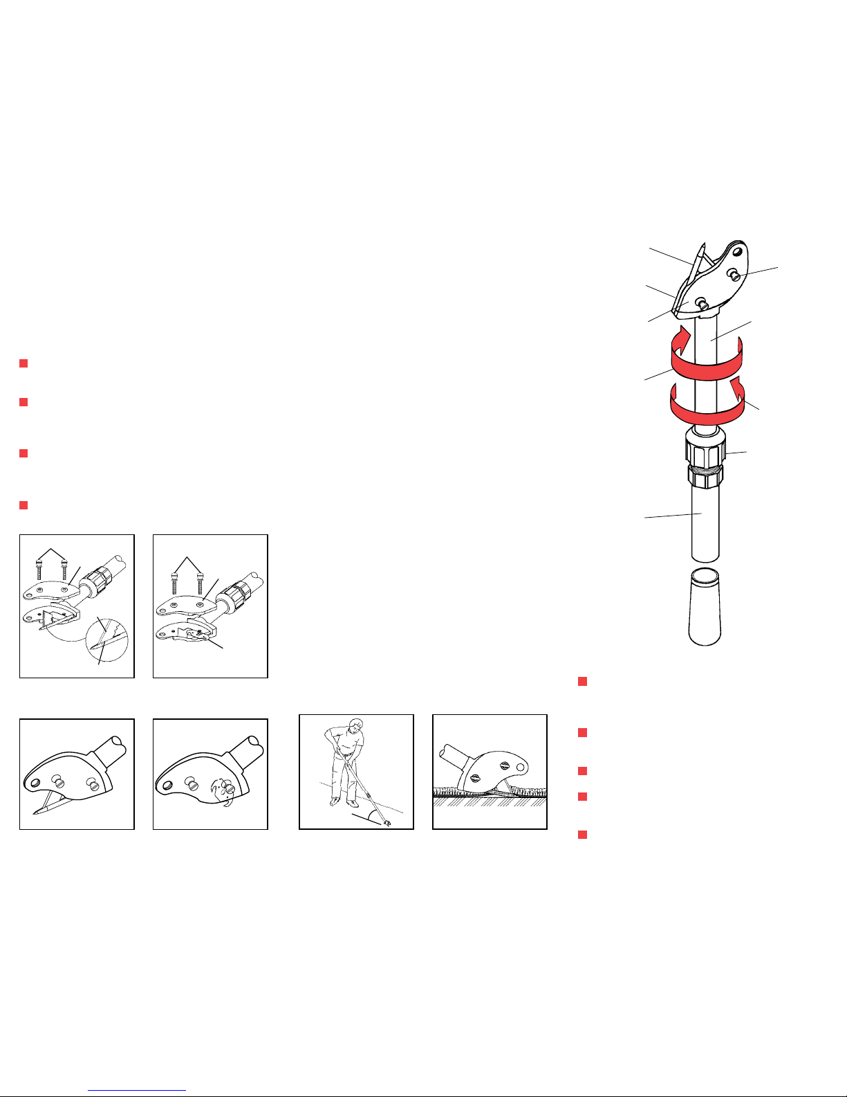
Loosen the two thumb screws to remove
blade clamp.
For utility blade: Put end of blade inside steel
pointer’s slot; then place both of them into the
cavities of the blade holder body (Figure 1).
For hook blade: Do not use the steel pointer.
Simply place new hook blade into the cavity
(see Figure 2).
Reinstall the blade clamp and tighten the two
thumb screws rmly before use.
Assembled with
Utility Blade
Assembled with
Hook Blade
Figure 1
Utility Blade Installation
Figure 2
Hook Blade Installation
HANDLE HEIGHT ADJUSTMENT
The Stand-Up Cutter is equipped with a strong
double-locking handle mechanism that will not
collapse under normal use. For your safety, always double-lock the handle before using the
cutter (see Figure 5).
STEP 1: Viewing the tool from the cutting end,
loosen the clamping ring.
STEP 2: Release previous lock by grabbing
tubes on either side of clamping ring and twisting
clockwise. When you hear a loud click, the lock
has been released.
STEP 3: Pull out extension tube to desired
length. The optimal cutting angle with the oor
is roughly 35 degrees (see Figure 3).
STEP 4: Re-lock the handle by again grabbing
tubes on either side of clamping ring and twisting
counter-clockwise until you hear a loud click. This
completes the rst lock.
STEP 5: Re-tighten clamping ring to complete
the second and nal lock you need prior to use.
USING THE STAND-UP CUTTER
To cut a strip of glue-down carpet, simply insert
the steel pointer through carpet, and push forward on the handle. The steel pointer guides the
carpet to the blade where it is cut (see Figures
3 & 4).
SAFETY TIPS
Shock hazard: avoid power lines. Check for
concealed electrical wiring. Keep tool 10 feet
from all electric lines.
Always make sure you double-lock the
handle before use.
Proceed at slow walking pace with the cutter.
Do not run! Suboor irregularity may cause
the steel pointer to catch and suddenly stop.
Always be aware of the sharp steel pointer
and blade when transporting in trucks or vans.
Figure 4
Point Lifts Carpet to Blade
Figure 3
Using the Tool
Figure 5
No. 266 Pointer
Thumb Screw
Blade Clamp
Blade Holder Body
Extension Tube
Clockwise
Direction to Lock
Counter Clockwise
Direction to Unlock
Clamping Ring
Handle Tube
THUMB SCREWS
THUMB SCREWS
BLADE
CLAMP
UTILITY
BLADE
POINTER SLOT
BLADE
CLAMP
HOOK
BLADE
35º
OPTIMAL
ANGLE
35º
 Loading...