

CRAIN 246 Instruction Manual
1155 Wrigley Way, Milpitas, CA 95035
TELEPHONE (408) 946-6100
CRAIN CUTTER CO., INC.
Printed by: HW 3M
GUARANTEE
This Carpet Trimmer is guaranteed to be free of defects
in workmanship or quality of materials for a period of
36 months.
Any parts of the tool found to be defective subject
to the guarantee will be replaced at no charge. Credit
in full or part cannot be extended by the distributor, nor
will new tools be given as replacements or loaners.
Tools subject to this warranty must be accompanied
by same, and returned freight PREPAID to Milpitas, CA,
and must be in assembled condition.
No. 246 CARPET TRIMMER:
Order No. Description
1246-B Base Only
1246-C Base and Mounting Bracket
1246-D Spacer Set (6)
1246-E Wall Runner
1246-F Blade Clamp Set (2)
1246-G Cover Plate
PARTS COMMON WITH THE No. 245
1245-A Mounting Bracket
1245-B Ratchet Handle
1245-D Three Arm Knob Set (3)
1245-S Carriage Bolt
1245-U Runner Pad
REPLACEMENT PARTS:
ORDERING INFORMATION:
Order No. Description Weight Blades
246 Carpet Trimmer 2.61 lbs. 184
FORM F1246-Rev. 05/05
FIG. 10
FIG. 11
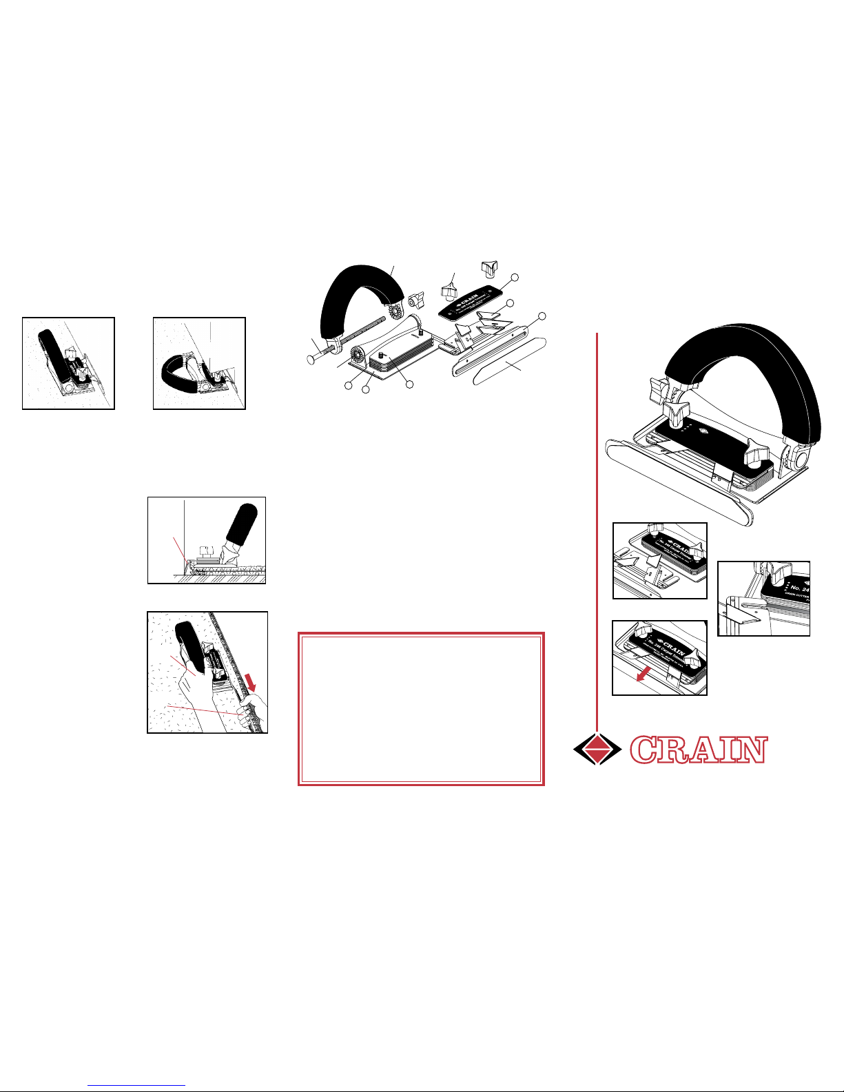
HANDLE ADJUSTMENT:
The handle is designed to fold down for trimming under
toe spaces. To adjust, loosen the three-arm knob at the
handle bolt, then press down on the top of the handle. You
can now rotate the handle, set at the desired height, and
retighten the knob.
1245-D
F
G
1245-U
D
E
1245-S
B
C
1245-A
1245-B
No. 246 CARPET TRIMMER
CRAIN
INSTRUCTION
MANUAL
FOR
PATENT PENDING
QUICK BLADE CHANGE
FAST REINSERTION
FAST THROAT
ADJUSTMENT
OPERATING:
Two or three feet from the corner, make a starter cut
three to four inches long, leaving excess carpet running
up the wall.
Place the trimmer into the
cut. Keep the bottom of
the trimm er flat against
the carpet, and the bottom edge of the wall runner at the junction of the
floor and the wall. (See
fig. 12.)
Push the tr immer along
the wall with your outside
hand. Using your inside,
or wall-side hand, pull the
ca rp e t be ing trim me d .
(See fig. 13.) The pulling tension on the cut-off
pi ece make s tri m mi n g
easier.
For a clean, smooth, finished edge, the excess is
tucked into the gully between the wall and tackless with a stair tool.
FIG. 13
WALL
FIG. 12
ANGLED
WALL
RUNNER
WALL RUNNER
EDGE MUST
FOLLOW
WALL
WALL
OUTSIDE
HAND
1.
2.
3.
4.
INSIDE OR
WALL SIDE
HAND
No. 246 Ca rpet T
rimme
r
CRAIN CUTTER CO.,
INC.
•
MILPIT
AS, CA
•
U.S.A.
PAT
E
NT PENDING
CRAIN
PULL
TRIMMED
PIECE
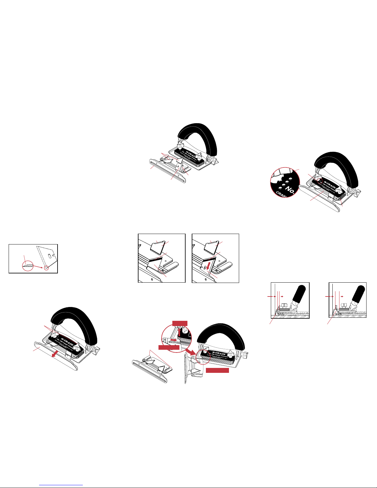
ADJUSTING THE TRIMMER:
BLADE SELECTION:
Top loading blade holders allows fast blade change.
Simple shim adjustment for height of cut. Shims need
not be removed to adjust cutting height. Built-in lifter
points on the wall runner make it easy to separate the
shims and re-insert the blade holder.
Four position adjustable throat to accommodate varying
pile height and density.
Ratchet handle folds down for trimming under toespaces.
Trims in both directions.
Stainless steel base plate and wall runner with plastic protective coating are both non-marking and will not rust.
FEATURES:
FIG. 1
BEVELED EDGE
•
•
•
•
•
•
Unlike utility blades, trimmer blades are beveled on one side
only. (See figure 1.) It is important to keep the beveled edge
of the trimmer blade up. This causes the nap of the carpet
being cut to be deflected up and away from the trimmer.
With the beveled edge of the blade down, the cut nap will be
pushed down, underneath the wall runner. This causes the
trimmer to rise and gives you a longer cut than desired.
USE ONLY TRIMMER BLADES!
ONLY ONE BEVELED EDGE
FACING UP!
#4
#3
#2
#1
The best multi-purpose setting for trimming most of today’s
carpets is:
THROAT OPENING: AT #2 HOLE
BLADE HEIGHT: 4 SPACERS
OPTIMIZING BLADE HEIGHT AND THROAT ADJUSTMENT:
The amount of carpet remaining after trimming is determined by BOTH the blade height AND the throat opening.
The THROAT OPENING holds carpet in proper position.
(See figure 8.)
The BLADE HEIGHT determines where the blade will cut.
(See figure 9.)
For example: A wide opening (throat position at #4 hole)
used on a thin carpet will give you a shorter cut, because
the carpet is not held upright, but allowed to lay at an angle.
(See figures 8 and 9.)
#1 IS NARROWEST THROAT
#4 IS WIDEST THROAT
INSERTING THE NEW BLADE:
Place a new blade bevel side up in the blade pocket, and
push it forward as far as possible until it contacts the inner
edge of the wall runner. After pressing the blade forward,
a rectangular hold in the blade pocket becomes visible.
Place the blade clamp back in the blade pocket with the
indent in the back edge of the blade clamp seated in the
rectangular hole.
As you are re-inserting the wall runner, you can seat it into
one of the four sockets which are visible from the top of the
shim deck. (See figure 7.) The four lines inscribed on the
top of the wall runner also provide a visual reference. The
line which is selected should be made parallel to the shim
deck for proper operation. Adjust the throat for specific
thickness of carpet to be trimmed.
THROAT ADJUSTMENT:
NARROW
THROAT
OPENING
WALL
WALL
WIDE
THROAT
OPENING
FIG. 8
FIG. 9
Wid e t hroat ope ning allo ws carpet to lay at an angl e, m aking a
shorter cut.
Narrow throat opening holds carpet
upright, allowing a longer cut.
WALL RUNNER
TRIMMER
BLADE
WALL RUNNER
BLADE
CLAMPS
FIG. 3
FIG. 2
Insert the lifter point of the wall runner into a lifter socket in
the shim deck that provides the desired height of cut. (See
figure 6.) Lifting at the corner allows the rest of the wall
runner to be easily reinserted.
WALL RUNNER REINSERTION AND BLADE HEIGHT:
FIG. 6
3. SLIDE IN
2. LIFT
1. INSERT
BLADE CHANGING - REMOVING THE WALL RUNNER:
Loosen both three-arm knobs on the top of the shim deck.
Lift the wall runner slightly and then pull out to remove it
from the shim deck.
THREE ARM
KNOBS
BLADE REMOVAL:
Lift the blade clamp out of the blade pocket area. You may
now remove the blade.
FIG. 4 - Blade Removed
BLADE POCKET
1. LOOSEN THREE
ARM KNOBS
2. LIFT SLIGHTLY,
THEN PULL OUT
FIG. 5 - Blade Inserted
BLADE
CLAMP
RECTANGULAR
HOLE
OPEN BLADE
POCKET
BLADE
CLAMP
RECTANGULAR
HOLE (SEAT
INDENT HERE)
INDENT
INDENT
INSERT BLADE &
PUSH FORWARD
SPACERS
THROAT ADJUSTMENT
LINES
FIG. 7
THROAT
ADJUSTMENT
SOCKETS
(4X)
(SEE BACK FOR MORE INSTRUCTIONS.)
LIFTER
POINTS
 Loading...