

Page 1
Page 2

CraftBot 3
TABLE OF CONTENTS
1. INTRODUCTION 3
1.1. Important 4
1.2. Warnings 4
1.3. Caution 4
1.4. Unpacking the printer 5
1.5. Contents of box 5
2. INTRODUCTION TO THE CRAFTBOT 3 6
3. ASSEMBLING THE PRINTER 7
3.1. Installing the encoders 7
3.2. Installingthelamentguidetube 7
3.3. Installingthelamentspoolholders 7
3.4. Moundingthelamentspools 8
3.5. Attachingthepowercord 8
4. FIRST STEPS 9
4.1. Switching on the appliance 9
4.2. Setting the language 9
4.3. Select the heat measure (Celsius / Fahrenheit). 9
4.4. Setting the clock 9
4.5. Connecting the CraftBot3 printer to a wireless network 10
5. PREPARING THE PRINTER 11
5.1. Heating up the printer 11
5.2. Loadingthelament 11
5.3. Removingthelamentfromtheextruder 12
5.4. Calibration settings 12
5.4.1. Leveling the build plate 12
5.4.2. Dual head calibration (Z) 14
5.4.3. Dual head calibration (X-Y) 16
5.4.4. FMS operation 17
5.4.5. Wizard settings 19
5.4.6. Other menu settings - adjusting the lighting 19
5.4.7. Activating the fans 20
5.4.8. Sound settings 21
5.4.9. Report function 21
5.4.10. Dome menu 21
5.4.11. Conguration of colored red strip 22
5.4.12. Printing modes 23
5.4.13. Reset settings /you can reset all the printer setting/ 23
6. NAVIGATE THE BUILD PLATE AND THE EXTRUDERS 24
7. USING THE PRINTER 25
7.1. Using CraftWare to convert 3D design into printing commands 25
7.2. dual head printing in craftware 26
7.3. Printingobjectsfromusbashdrive 28
7.4. In-printadjustment 28
7.4.1. Tweak function menu 29
7.4.2. Pause next layer menu 29
7.4.3. Pause menu 30
8. MOBILE APPLICATION 30
8.1. Usingcraftwaretoconvert3ddesignintoprintingcommands 30
9. CLEANING AND MAINTENANCE 31
10. TROUBLESHOOTING 32
10.1. Preventing/xingacloggedextruder 32
10.2. Removing the nozzle 33
11. FIRMWARE UPDATE 34
11.1. Firmware update with software 34
11.2. Firmware update on older printers 36
12. APPLYING A NEW LAYER OF PROTECTIVE KAPTON SHEET TO YOUR BUILD PLATE 36
13. USEFUL THINGS 37
13.1. G and M codes 37
13.2. Useful links 40
14. GUARANTEE 41
15. LIMITATION OF LIABILITY 41
2
Page 3
CraftBot 3
1. INTRODUCTION
Congratulations on your purchase of the CraftBot 3D printer and welcome to the word of 3D crafting!
At CraftUnique we believe that 3D printing opens a new window to enhance creativity. It oers
outstanding crafting experience even without prior programming or 3D printing experience.
How does the printer work? The CraftBot 3D printer makes solid, three-dimensional objects out of
melted plastic lament. Design Your objects with the help of a 3D design program. Then use the
CraftWare program (downloadable from www.craftunique.com/craftware) to transform Your 3D
design les into printing instructions for the CraftBot 3D printer. Transfer this to Your CraftBot 3D
printer via USB drive or USB cable. The CraftBot 3D printer will melt plastic laments and squeeze it
out onto the building plate in thin lines to print your object layer by layer.
3
Page 4

CraftBot 3
1.1. IMPORTANT
Read this user manual carefully before you use the appliance, and save it for future reference.
All information in this user manual is subject to change at any time without notice and is provided for
convenience purposes only. CraftUnique reserves the right to modify or revise this user manual in
its sole discretion and at any time. By using the manual, you agree to be bound by any modications
and/or revisions. For up-to-date information contact the CraftUnique Service Support
([email protected]).
1.2. WARNINGS
• Check if the voltage indicated on the sticker at the back of the appliance that it corresponds
to the local mains voltage before you connect the appliance.
• Do not immerse the power cord, plug or any other parts into water or any other liquid. This
may cause electrical shock.
• Do not use the appliance if the plug / mains cord or the appliance itself is damaged or not
operating properly.
• If the mains cord is damaged, you must have it replaced in order to avoid hazard.
• Only connect the appliance to grounded wall sockets.
• Keep the mains cord away from hot surfaces.
• Do not let the mains cord hang over the edge of the table or worktop on which the appliance stands.
• Keep the appliance and its cord out of the reach of children.
• This appliance can be used by children from the ages of 8 years and above; and by persons
with reduced physical, sensory or mental capabilities or lack of experience and knowledge. Only
under supervision and adequate instruction concerning the use of the appliance in a safe way,
understanding the hazards involved. Cleaning and user maintenance shall not be made by children.
• Children can receive great educational benets from designing 3D objects. But the printing process
should not be done by small unsupervised children.
• Do not touch moving parts or heated elements, it can cause injuries.
• Never reach inside the machine when turned on. Dierent parts of the machine (mainly the extruder
and heated build plate) operate at very high temperatures and can cause severe burns.
• Never leave the CraftBot 3D printer unattended while it is plugged in and is in operation.
• Make sure that the power supply is o and that the power cord is disconnected before servicing. Allow
at least 5 minutes for the device to cool down after unplugging it before reaching inside to service.
• Always turn o the printer and disconnect from the computer when it is not being used.
4
1.3. CAUTION!
• Make sure to level the build plate properly before use.
• Make sure not to force anything, whether it be during unpacking, setup, operation or service.
• Service and oil the suggested parts as often as recommended. Use only substances recommended
by CraftUnique. (Normally after every 50 printing ours)
• The CraftBot 3D printer melts plastic during printing. Plastic odors are emitted during this operation.
Make sure to set up the CraftBot 3D printer in a well-ventilated area.
Page 5
CraftBot 3
1.4. UNPACKING THE PRINTER
3 4 6 10
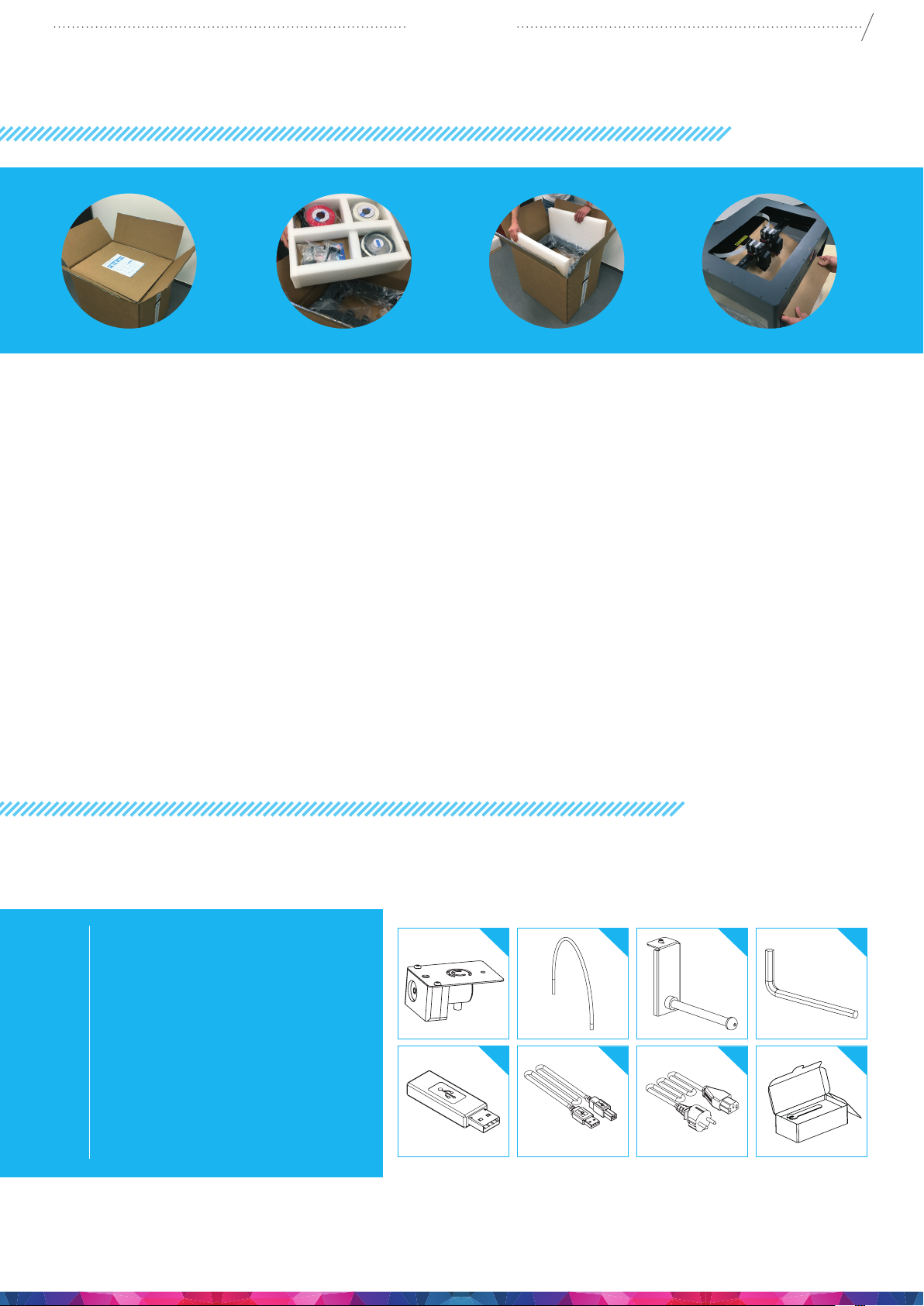
1. Place the CraftBot cardboard box on an even surface with open space around.
2. Open the box with care, avoid damaging the contents when using any cutter tools.
3. Remove the protective cardboard cover. You will nd the Quick Start Guide at the top of the inner
packaging.
4. The accessories (including a USB pen drive with copy of the CraftBot user manual) are placed in the
upper foam tray. We suggest keeping the accessories in a secure place, avoid losing them.
5. The CraftBot 3D printer is under the upper foam tray enclosed in a protective plastic bag supported
with side foams to avoid any damage while shipping.
6. First remove the side foams then open the plastic bag.
7. Firmly grasp the frame of the CraftBot under the LCD screen and the handle at the back of the
printer. Make sure not to touch the extruder or the electronic panel inside the device!
8. Consider its weight. Request physical help if needed. Lift the printer from inside the plastic cover
and remove it from the cardboard packaging.
9. Place the CraftBot 3D printer on a stable and even surface with sucient space around.
10. Remove the cardboard panel xing the two heads inside the printer.
5
1.5. CONTENTS OF THE BOX
It’s time to unpack additional parts. Below you can see the contents of the box. First of all, check the
list to make sure nothing is missing!
1. Filament encoder (2x)
2. Filament guide tube (2x)
3. Filament spool holder (2x)
4. Hex wrenches (5x)
5. USB Flash storage
6. USB A-B cable
7. AC power cable
8. 2x Nozzle kit boxes which
includes assortment of Nozzle
tips, Spacer cards, and a nozzle
spanners/Wrench
You should also get 2 spools of 0.75kg PLA lament, along with an assortment of colours to get you
started along with the box containing your CraftBot.
1
5
2
6
3
7
4
8
Page 6

CraftBot 3
2. INTRODUCING THE
CRAFTBOT 3D PRINTER
6
2
2
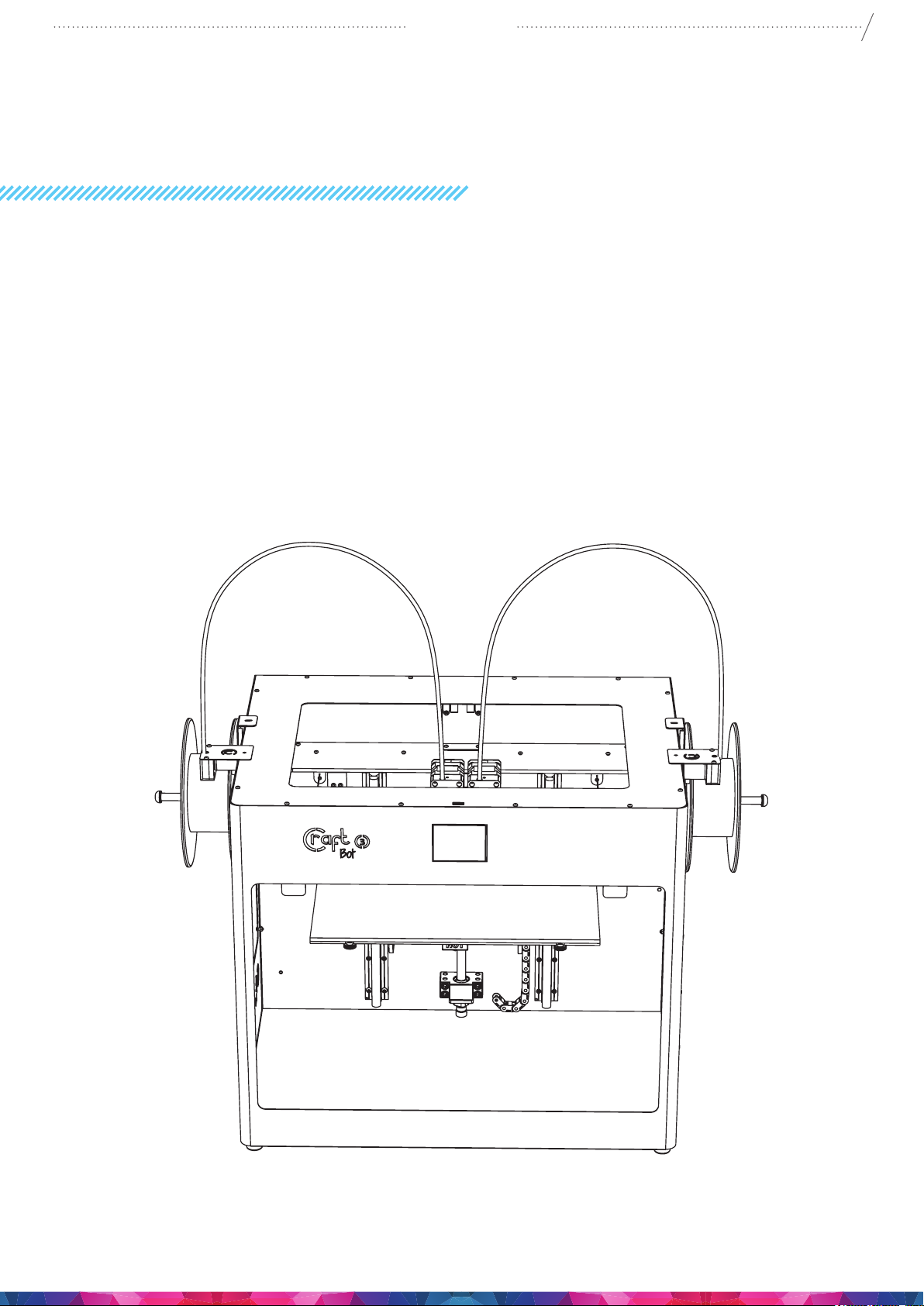
1. Touchscreen LCD display
2. Filament guide tube
3. Separated dual heads
4. Removable build plate
5. Leveling knobs
6. Filament spool holder
7. Filament spool
8. FMS encoder
9. USB for ash drive
10. USB for PC connection
11. AC power socket and ON/OFF switch
12. Encoder 1 connection
13. Encoder 2 connection
14. Z Spindle
15. Z screw top support screws
15
4
9
8
1
3
15
14
5
8
7
6
11
10
13
12
Page 7
CraftBot 3
3. ASSEMBLING THE PRINTER
3.1. INSTALLING THE ENCODERS
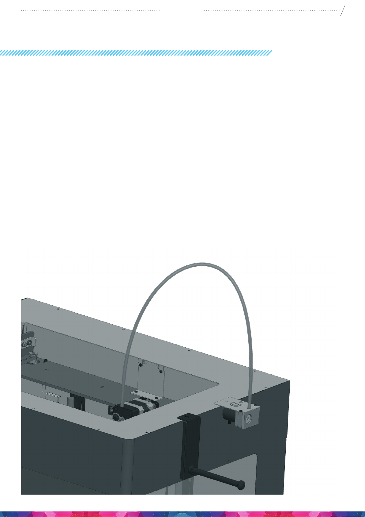
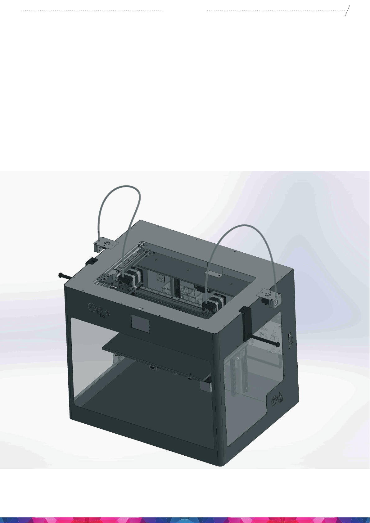
• Select the desired position for the encoders. Choose their position so that the lament spool bracket
ts beside them. And the lament drives directly up into the encoders from the spool.
• Plug the 2 Encoder cables into the encoder ports on the side of the printer. found beneath the USB
connector on the side of the machine. The upper one is number 1 and the lower one is number 2.
• When looking at the machine, the extruder on the left side is number 1, and the extruder on the
right is number 2.
3.2. INSTALLING THE FILAMENT GUIDE TUBE
• Fit the lament guide tube to the top of the extruder and the top of the encoder.
7
3.3. INSTALLING THE FILAMENT SPOOL HOLDERS
• Locate both of the lament spool holders.
• Using a hex wrench, install the lament spool holder next to the 2 FMS Encoders.
Page 8
CraftBot 3
3.4. MOUNDING THE FILAMENT SPOOLS
• Fit both of the lament spools onto the lament spool holders, so that the lament feeds, directly
up into the Encoder and up into the guide tube.
3.5. ATTACHING THE POWER CORD
• Ensure that the power switch on the CraftBot is set to the OFF position.
• Find and insert the AC power cord into the power input on the back of the CraftBot.
8
Page 9
CraftBot 3
4. FIRST STEPS
4.1. SWITCHING ON THE APPLIANCE
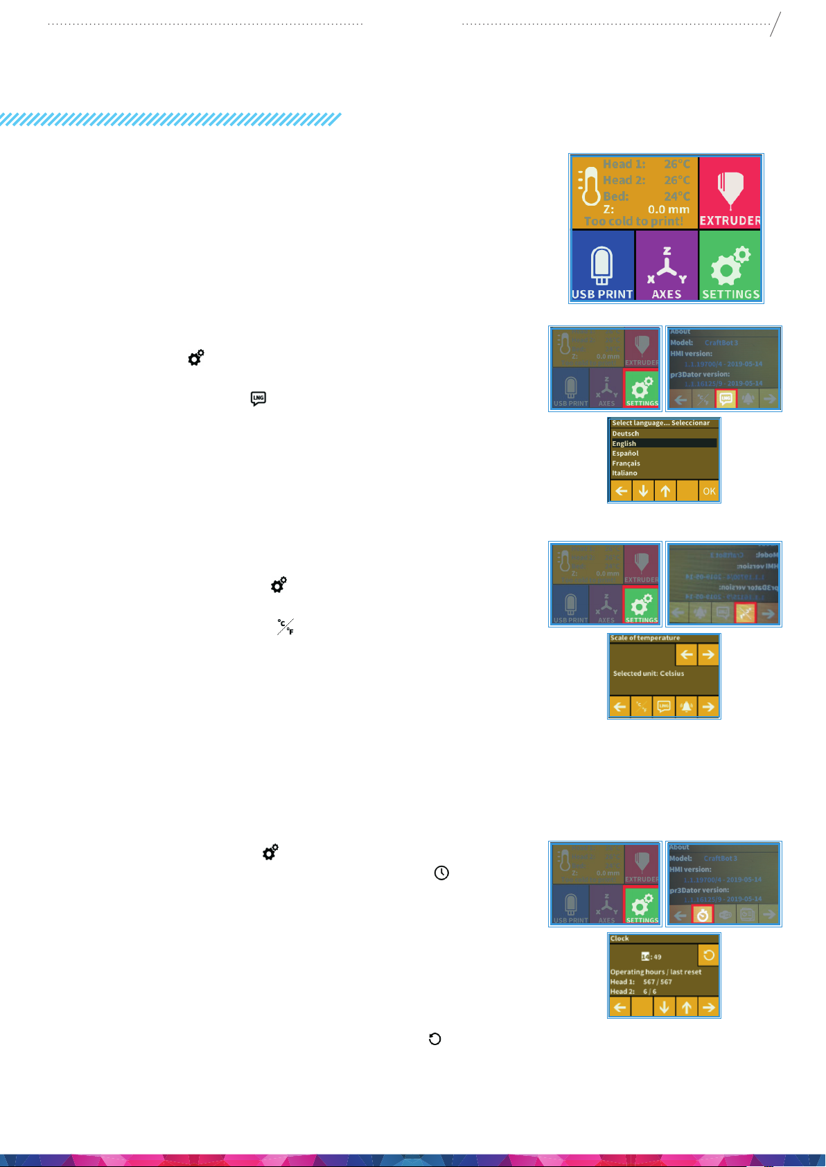
• Switch on CraftBot by the ON/OFF button located
on the back part of the appliance.
• The LCD panel on the front will light up.
4.2. SETTING THE LANGUAGE
• Go to „Settings” on the LCD screen and go to page 2 using
the right arrow icon.
• Select the language icon .
• Select by scrolling to the desired language.
• Conrm your selection by using the OK icon.
• Use the left arrow at the bottom of the screen to get back
to the main menu.
9
4.3. SELECT THE HEAT MEASURE
Temperature can be displayed in Celsius or Fahrenheit.
• Select the Settings menu on the LCD screen and go
to page 2 using the right arrow icon.
• Select the temperature icon
• The unit can be changed by pressing the right or the left
arrows at the top of the screen.
• Use the left arrow at the bottom of the screen to get back
to the main menu.
4.4. SETTING THE CLOCK
You can set the time and reset the operating hour counter. This
function helps to track printing time between maintenance
sessions.
• Select the Settings menu on the LCD screen and go to
page 3. using the Right Arrow. Select the clock icon
• Set the time by using the Up and Down Arrows. To switch
between Minute and Hours just push pushing the Right
Arrow.
• Total operating hours are measured and cannot be reset
back to 0.
• The individual head counters at the bottom has 2 counters,
total working hours and / time between each maintenance
period, you can reset this by using the reset icon
Top Right of the screen.
button,
Page 10

CraftBot 3
4.5. CONNECTING THE CRAFTBOT3 PRINTER TO A WIRELESS
NETWORK
• Select the Settings menu n the LCD screen and go to page
3 with right arrow. Select the Wi-Fi icon
• Select the search Wi-Fi Network” icon – the third icon in the
bottom row.
• Scroll down with up-down arrows. Select desired network
with the left arrow.
• Enter password.
• Conrm password with the tick mark
corner.
• Selected Wi-Fi network is displayed indicating host name
and LAN IP.
• By pressing the “eye” icon you can toggle the wi’s visibility
on / o.
• SSID: You can modify the printer’s unique identier name.
click on the SSID icon to the right make your changes and
conrm it.
. In the right bottom
10
Page 11
CraftBot 3
5. PREPARING THE PRINTER
5.1. HEATING UP THE PRINTER
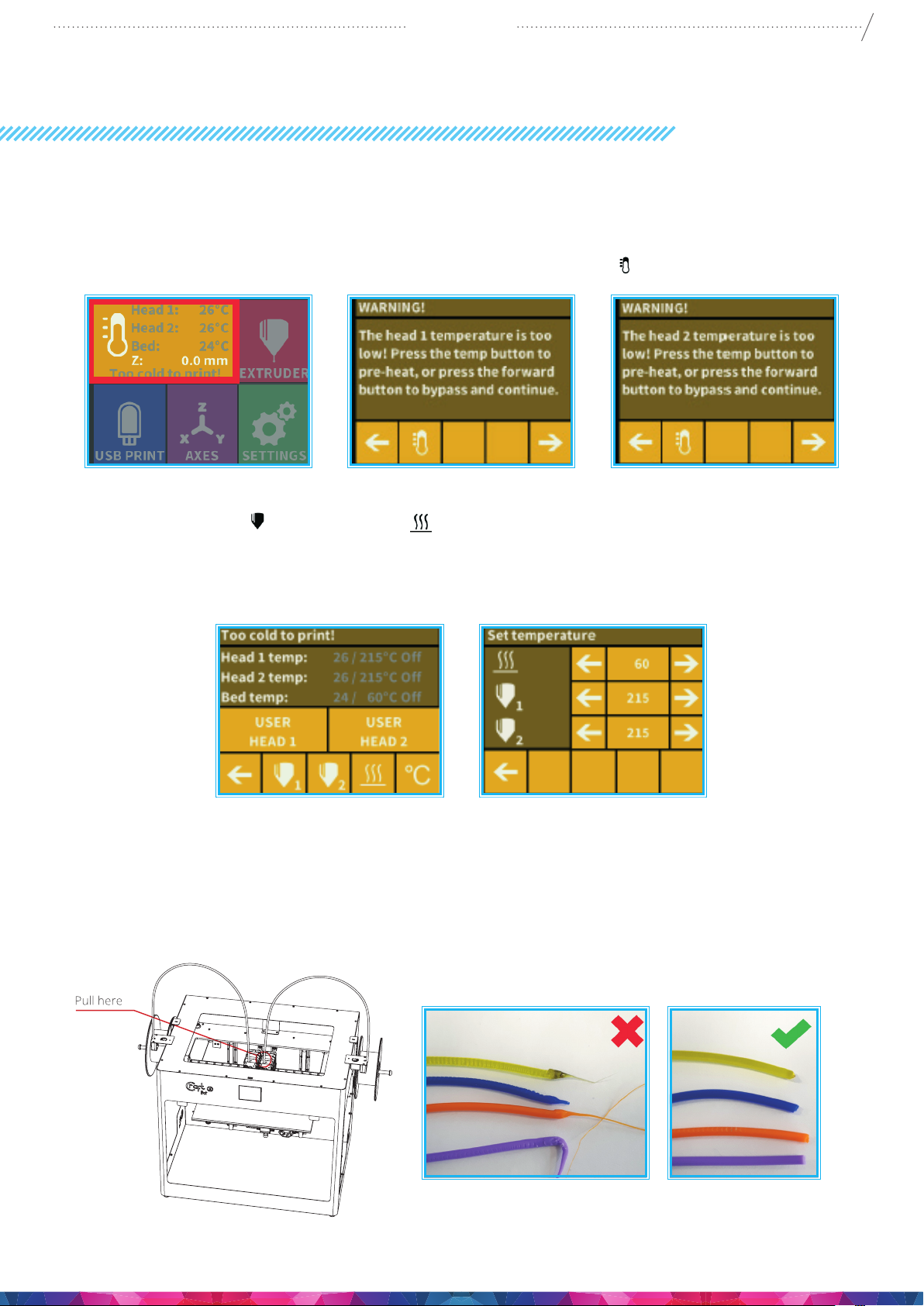
For printing or loading / unloading the lament, heat up the printer according to the type of lament
you are printing with. On the main menu press the thermometer icon.
11
At this point you will see a new menu indicating both Head temps” plus the “Bed temp”.
Select the Extruder icon
heating process. Once the extruder reaches the target temperature of your lament (keeping in mind
that dierent materials such as PLA, ABS, and PET have dierent temperature settings), you can start
printing.
5.2. LOADING THE FILAMENT
1. Heat up the printer.
2. Remove the lament guide tube from the insert hole on top of the extruder.
and the Bed icon (line with 3 wavy lines above) to commence the
Page 12
CraftBot 3
3. Cut the end of the lament free from any kinks and bad ends. Insert the lament from the spool into
the bottom hole of the lament FMS encoder. Please make sure that the lament spool feeds directly
into the FMS encoder from the bottom so that the lament keeps itself straight on course and free
from any snagging. This way you will avoid any unnecessary bending of the lament and any wrong
diagnostics from the lament monitoring system.
12
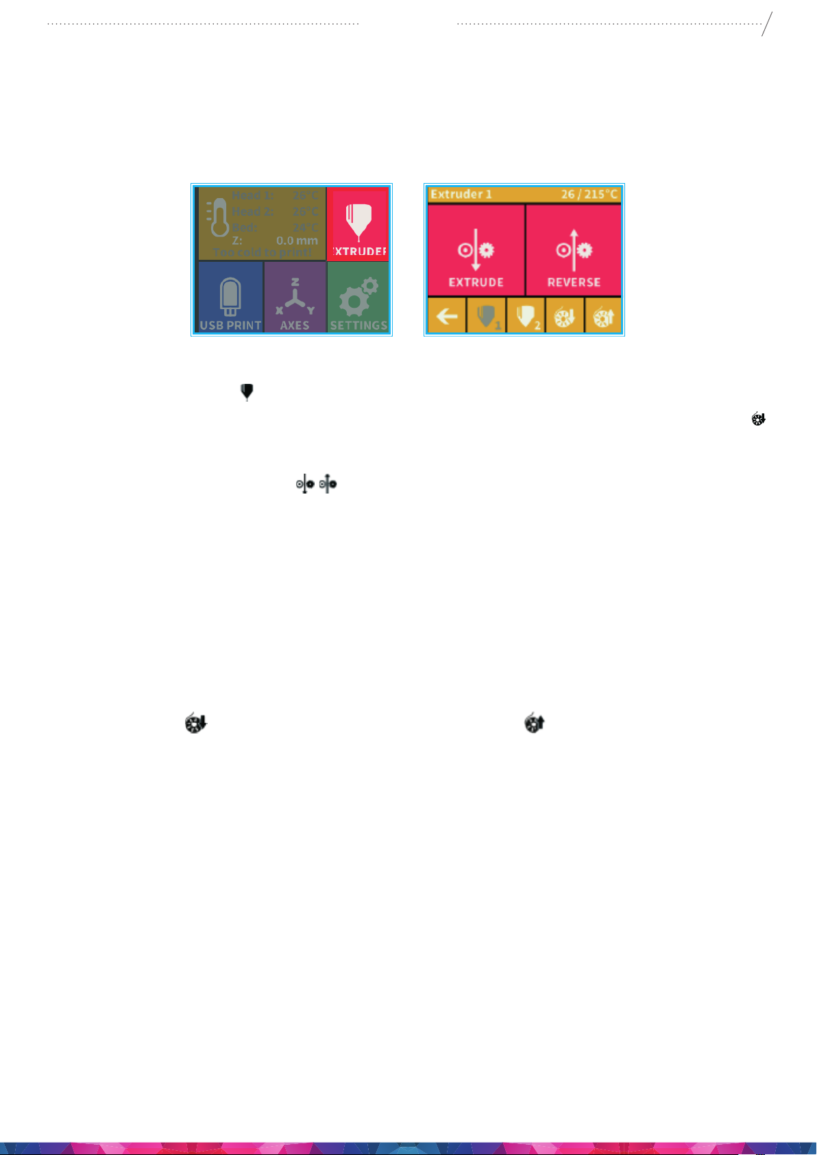
4. Enter into the extruder
5. Press the bottom icon for the extruder you are about to use now using or load lament button
on the screen. The load button will extrude 15 cm of lament automatically, this can be interrupted
by pressing the back button at any time.
6. You can also use the “extrude”
nozzle manually. Re-insert the lament guide tube back into the hole at the top of the extruder. The
two heads and the build platform can now be set individually.
5.3. REMOVING THE FILAMENT FROM THE EXTRUDER
Never remove the lament from the extruder if the extruder is cold! Always preheat the extruder before
removing or changing laments. Removing the lament from a cold extruder might damage it! You
don’t have to remove the lament between prints.
1. Heat up the extruder rst to the correct temp for that lament type.
2. Press the Load
extrude a small amount of lament to prevent clogging and switch into reverse until lament
removed from the extruder head.
3. Once the gears have begun to retract the lament you will be free to pull it out from the printer back
to the spool ready to load a new lament.
rst for 1 or 2 seconds and then press the button. This will automatically
menu. Push the lament into the extruder hole, against the drive gear.
menu on the touchscreen to extrude lament in /out of the
5.4. CALIBRATION SETTINGS
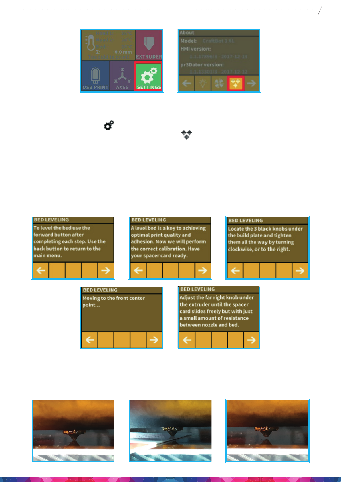
5.4.1. LEVELING THE BUILD PLATE
CraftBot has a leveling procedure which ensures that the extruder and the heated build plate are at optimal
distance and they must be leveled evenly. Smaller gap or uneven levelling may lead to the damaging of the
Kapton cover sheet on the build plate or the extruder itself.
After calibrating the build plate the Z-calibration is recommended.
Page 13
CraftBot 3
Calibration process:
1. Heat up the heads and remove the laments. It’s easier without lament.
13
2. Select the Settings menu
circles which represent the three knobs and screw)
3. Follow the step-by-step instructions on the LCD screen:
on the LCD screen go to. page 1 select the Leveling icon (three crossed
.
• It is recommended to turn all three black knobs holding the build plate, all the way to the right until
the springs in between have been compressed fully and the knobs begin to feel tight. (Under the
heater plate There is one knob at the front in the middle and two in the back left and right corners
of the build plate). Do not force them!
• Locate the 0.35mm spacer card that are located in the Nozzle kit boxes among the other accessories
that came with the printer. This card will ensure the optimal distance between the build plate and
the extruder nozzle. Please keep this card for future use.
• The preprogrammed leveling process will rst set the front center point. Press the right arrow to
continue. wait for the nozzle to get to the correct point on the build plate. Place the spacer card
above the front center black knob on the build plate, Adjust the front center knob if needed, based
on the instruction on the screen.
Page 14
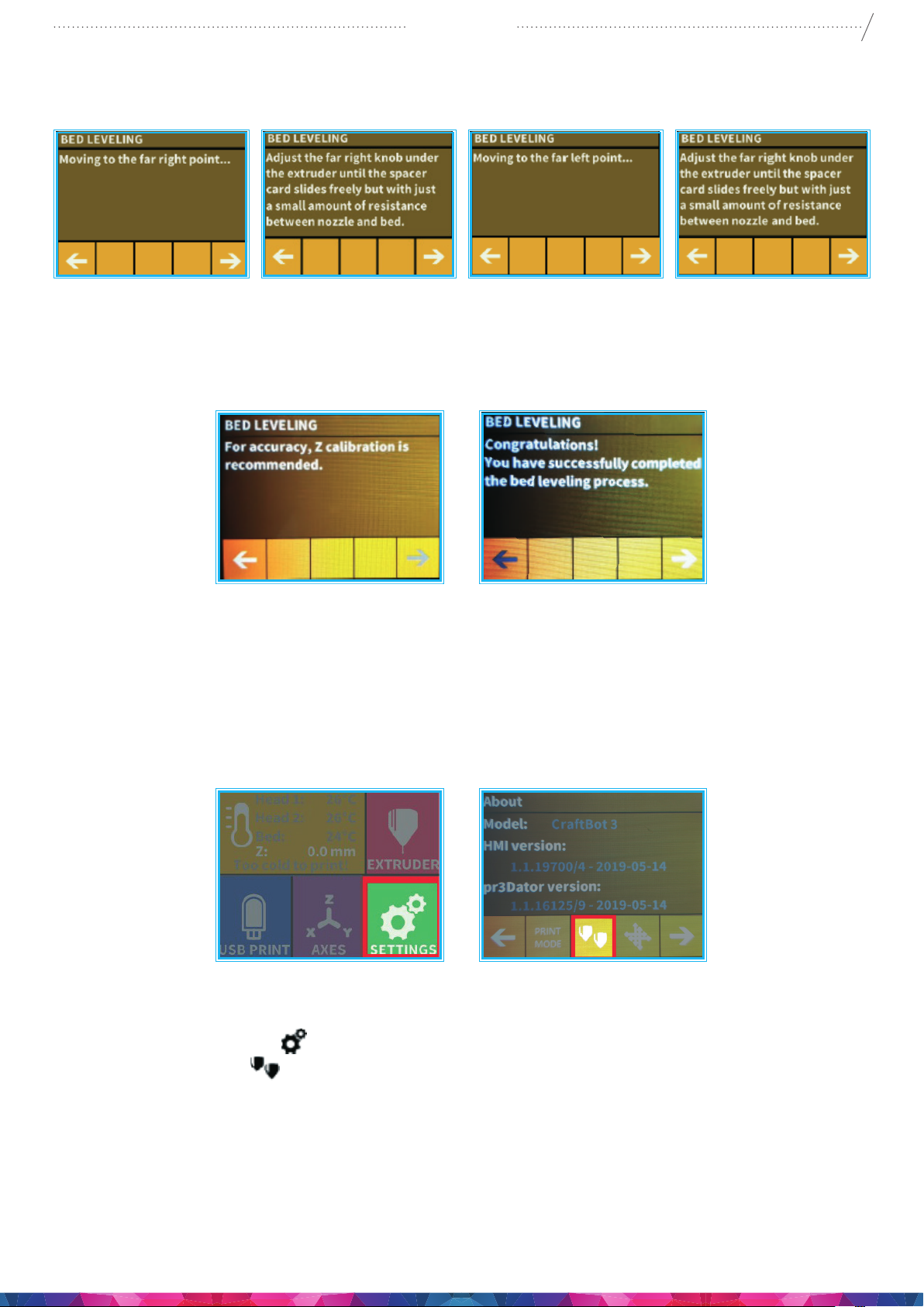
CraftBot 3
4. Repeat the process with the two back knobs. First the right back, then the left back knob will be
adjusted.
5. Before switching from knob to knob, please remove the leveling card. When the nozzle is in the
correct location replace the card as necessary for further testing at that location point.
6. Process is to be repeated twice to make sure that all 3 knobs are in the correct position.
7. As a result, the building plate should be evenly calibrated.
14
8. You can return to the main menu by pressing the right arrow.
5.4.2. DUAL HEAD CALIBRATION (Z)
The Z axis must be calibrated so that the two heads are at the same height and are at the same distance
from the build platform. If there is a height variation between the two heads, it will be visible on the
printed object.
Calibration process:
1. Heat up the heads and remove the laments!
2. Select the Settings menu
the Z calibration icon
on the LCD screen and go to the 5th. page using the right arrow. Select
. 2 printheads icon.)
3. The calibration must be initiated
4. select the 2 arrow icon
Page 15
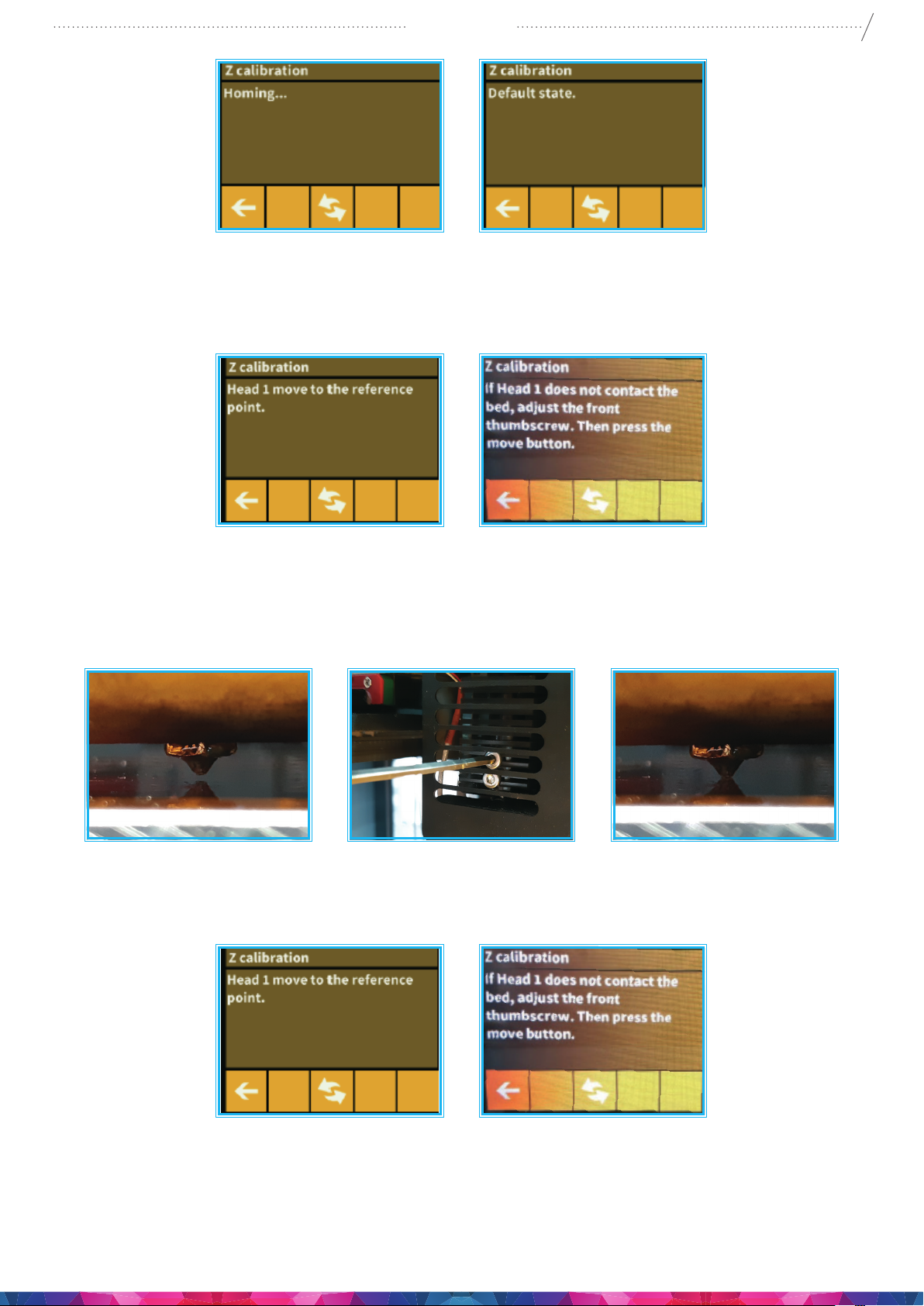
CraftBot 3
5. When the rst head has moved to the reference point which will be at the front screw point, the build
platform and the nozzle tip must be set perfectly to each other with the nozzle JUST touching the
surface of the build platform. with no space between nozzle and bed.
6. Then, press the change heads button in the middle.
15
7. The First head will move back to the home position and the second head will move to the same
reference point at the front of the build platform.
8. loosen the two screws on the left side of the Black heatsink. Drop the nozzle to the bed and tighten
the screws.
9. Repeat this twice to make sure that both heads 1 and 2 are at the correct same Z height position.
If you have moved the build plate leveling screws please go back to redo a bed leveling.
Page 16
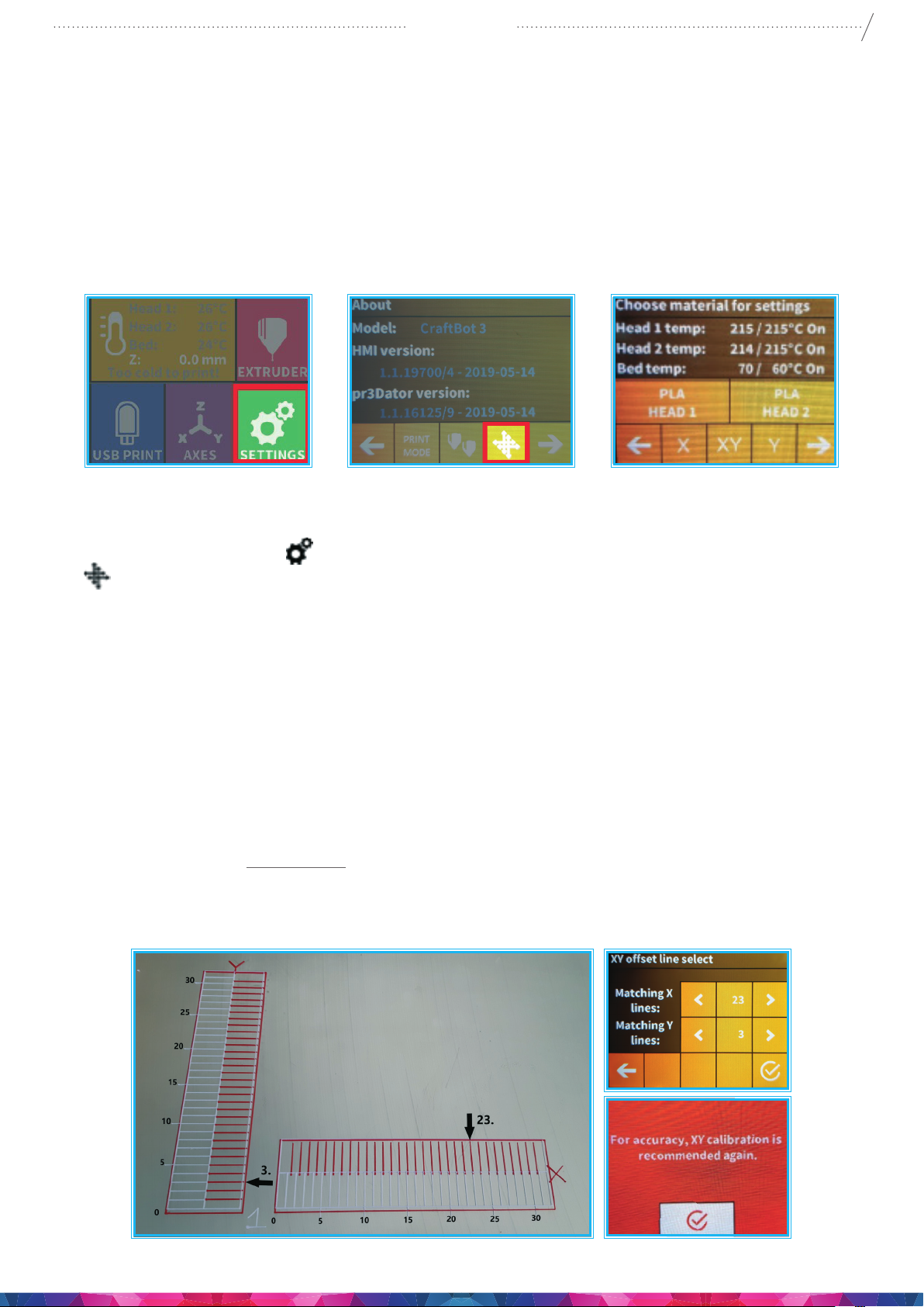
CraftBot 3
5.4.3. DUAL HEAD CALIBRATION (X-Y)
The X-Y axis must be calibrated so that the coordinate system of the two heads is completely aligned. So,
if we send both heads to the same coordinates then they should be at the same point. This is important
when we are printing an object with both heads. If there is any deviation, the print will be misaligned;
for example, if there is a gap between two materials or if the two materials are printed onto each other.
Calibration can be performed on the X and Y Axes individually, or on both axes at the same time in an
automated program by using centre XY button.
16
Calibration process:
1. Heat up the heads and load the laments into both extruders!
2. Select the Settings menu
(to the oset coordinate systems)
3. Head and bed temperature must be entered (what material is placed into the extruder head: ABSPLA-PET)
4. Start the calibration of the X, Y, or the automated XY axes
5. The printer will print the calibration lines with both printheads. It will print the number 1 next to the
rst line.
6. The user must determine which of the lines printed by the two heads is aligned fully.
This head’s number must then be chosen from the display after the printing. In the case of the
simultaneous calibration of both axes, the matching lines must be given rst for the X, then for the
Y axis.
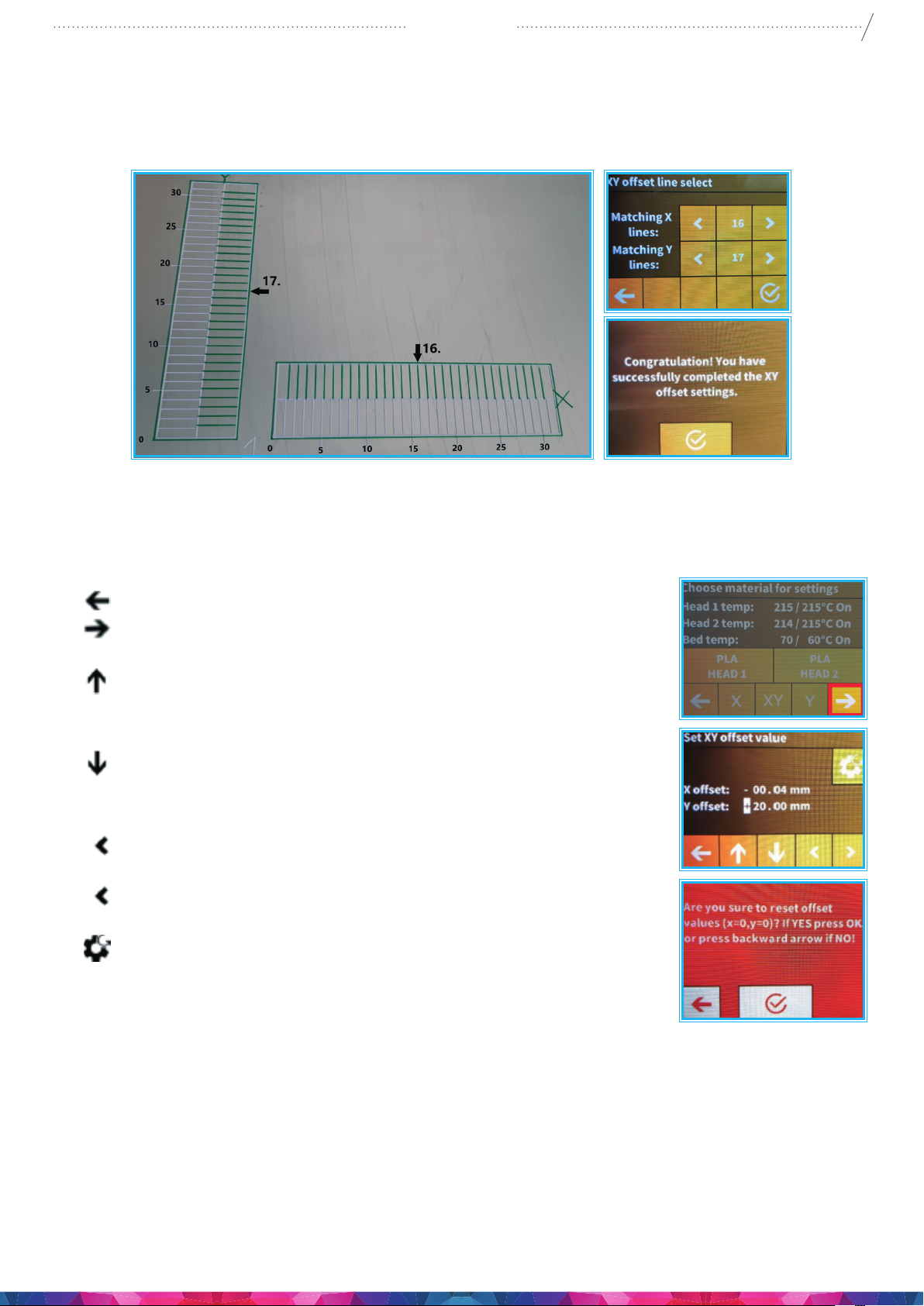
7. To make sure it is calibrated and the 16th lines are aligned.
8. When your lines are Not aligned at the 16th lines:
• Chose the head’s number in the LCD screen, and wait for the text message. If you see the red
message, the calibrate is not correct so you need to start a new XY calibration with the new rate.
on the LCD screen and go to the 5th page. Select the calibration icon
Page 17
CraftBot 3
9. When your lines aligned in the 15th, 16th or 17th lines:
• Chose the head’s number in the LCD screen, and wait for the text message. If you see the yellow
congratulation message, the calibration is correct and you can exit to the main menu.
17
10. When you have completed the calibration the rst time An extra second or third calibration is always
recommended to get the perfect settings.
• Left arrow : you can step back to the X-Y main menu.
• Right to ne tune the X,Y calibration settings in the Set the X,Y
oset page.
• Up arrow: you can enlarge the number’s value.
X oset +1 Moving the lines to the right with 1 mm.
Y oset +1 Moving the lines to the up with 1 mm.
• Down arrow: you can reduce the number’s value.
X oset -1 Moving the lines to the left with 1 mm.
Y oset -1 Moving the lines to the down with 1mm.
• Left arrow head: you can move between selected number
groups you wish to change
• Right arrow head: you can move between selected number groups
you wish to change
• Reset icon: you can reset the values.
5.4.4. FMS OPERATION
The lament monitoring system observes the lament ow during printing. If the printer detects a jam
during printing, it will try to resolve it on its own. If it is unable to resolve the jam, then an error message
will appear on the display, the message will appear in the application, and the printer will also send an
email message. Please note, the wi should be set up correctly rst.
Page 18
Calibration:
CraftBot 3
18
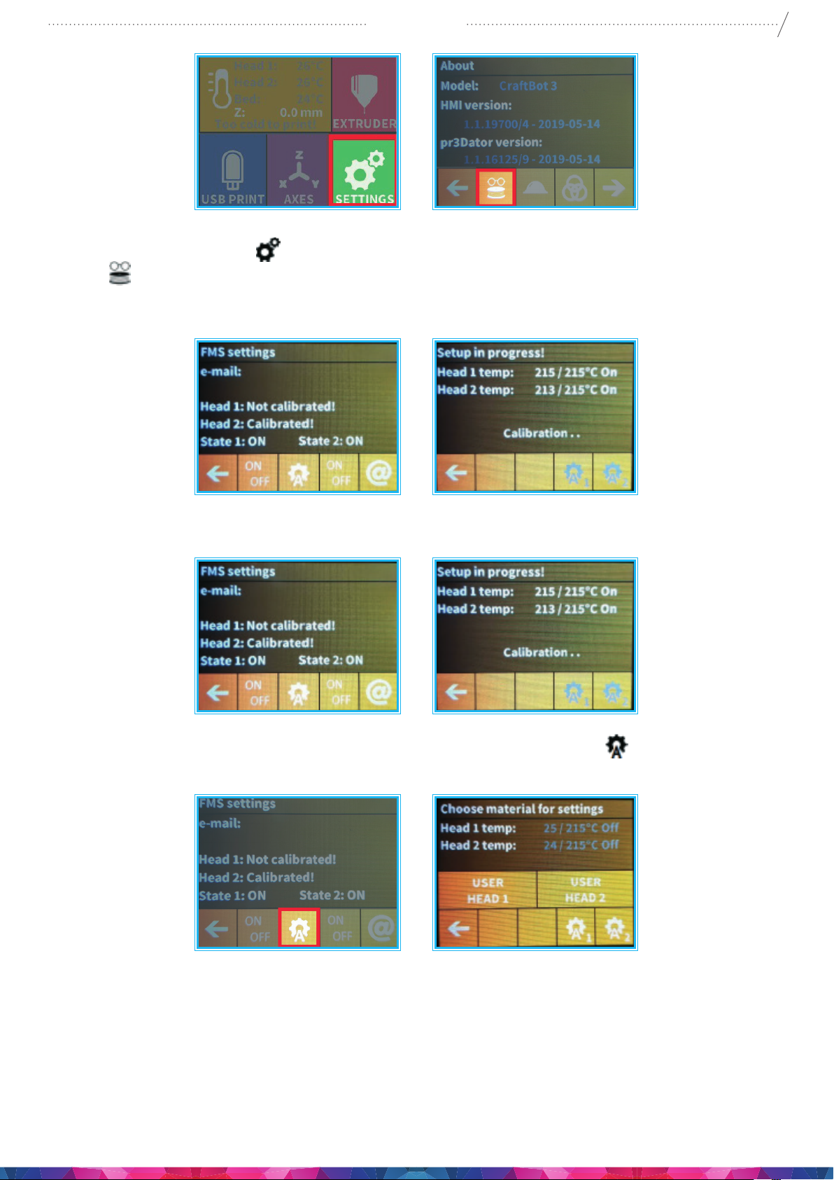
1. Select the Settings menu
icon
2. Here you can view the status and see whether the function is turned on or o. You can change this
with the rst button.
3. You can provide your email address into the system just go to the @ icon, The printer will automatically
send a message if it is unable to resolve a jam.
.
on the LCD screen and go to the 4th page. Select the encoder settings
4. Calibration can be initiated by touching the icon resembling an A with a cog
temperature here. You can calibrate the appropriate encoder with the help of the rst two icons.
5. A test message can be sent after calibration so the user can check whether the email function is working.
In addition to the email, a message will also appear in the application and on the FMS reporting.
. You can set the head
Page 19
CraftBot 3
Automatic error correction process: :
• The printer enters paused status, the head goes to the pause position.
• It then retracts the lament, following which it attempts to extrude.
• Point two will be attempted three times.
• It will attempt to extrude 6cm of lament to determine whether extrusion will cause clogging. again
• If not, then printing will resume automatically. If it does, an error message will be sent.
• If the user has resolved the error, you can press resume printing to continue printing immediately.
5.4.5. WIZARD SETTINGS
19
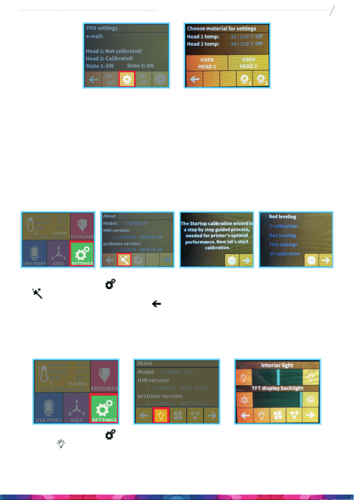
All calibrations are available in this menu. If you start the wizard, then it all calibration starts by itself.
1. Select the Settings menu
(magic wand).
2. Select the right arrow in the right corner.
3. Do all calibration.
5.4.6. OTHER MENU SETTINGS - ADJUSTING THE LIGHTING
on the LCD screen and go to the 6th page. Select the wizard settings icon
1. Select the Settings menu
settings
2. You will see a variance pop up on the screen: two dierent touch screen sliders.
3. Adjusting the lighting: Move the line from the left to the right to vary the brightness of either the
interior LED lighting of the CraftBot or the LCD display backlighting.
icon.
on the LCD screen and on the 1st page select the Lighting
Page 20
CraftBot 3
5.4.7. ACTIVATING THE FANS
CraftBot has ve fans: object 1 fan, extruder 1 fan, object 2 fan, extruder 2 fan, case fan, and dome fan.
You can Activate and deactivate some of these fans while the printing is taking place. (The dome has to
be activated and set before printing starts).
20
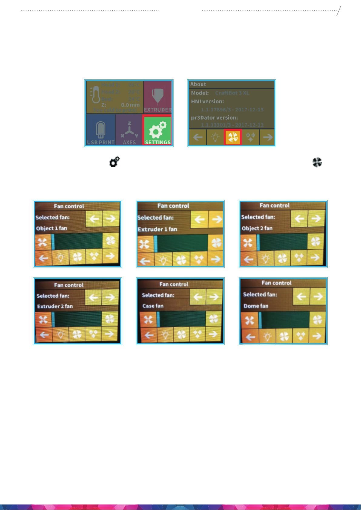
1. Select the Settings menu
2. Switch between fans by pressing arrows at the top of the screen. The name of the fan to be controlled
is displayed on the left of the screen.
on the LCD screen and go to the 1st page select the Fan control icon.
Fan Control: Activate and deactivate the fans before or during printing to match your preferences.
Extruder and case fan settings automatically reset to default after 60 seconds.
Page 21
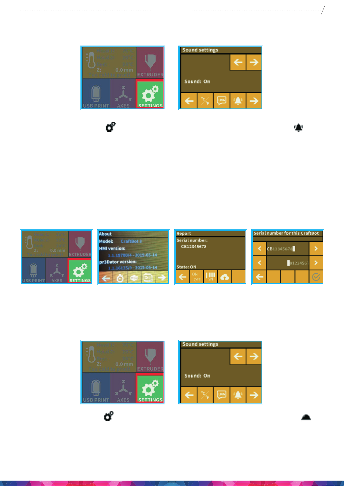
5.4.8. SOUND SETTINGS
CraftBot 3
21
1. Select the Settings menu
2. Use the arrows in the top right corner you can choose between 3 options: Sound On, Sound O and
Warnings Only.
5.4.9. REPORT FUNCTION
Registered users on Craftunique website can register their printer using its serial number on the
website. After registration, when the function switched on if the printer is connected to wi then the
printer every day at midnight or at the very rst power on that day, it will send the actual hours of
operation, and the lament usage of the printer to the website.
on the LCD screen and go to the 2. page. Select the Bell icon .
On the website with the help of time ltering users can check their printers usage (how many hours they
printed on a day) and how much lament used.
5.4.10. DOME MENU
1. Select the Settings menu
2. If the dome is mounted you can turn on the dome’s fan here. If the dome is turned on then the
dome fan will work during printing.
on the LCD screen and go to the 4th page. Select the Dome icon .
Page 22
CraftBot 3
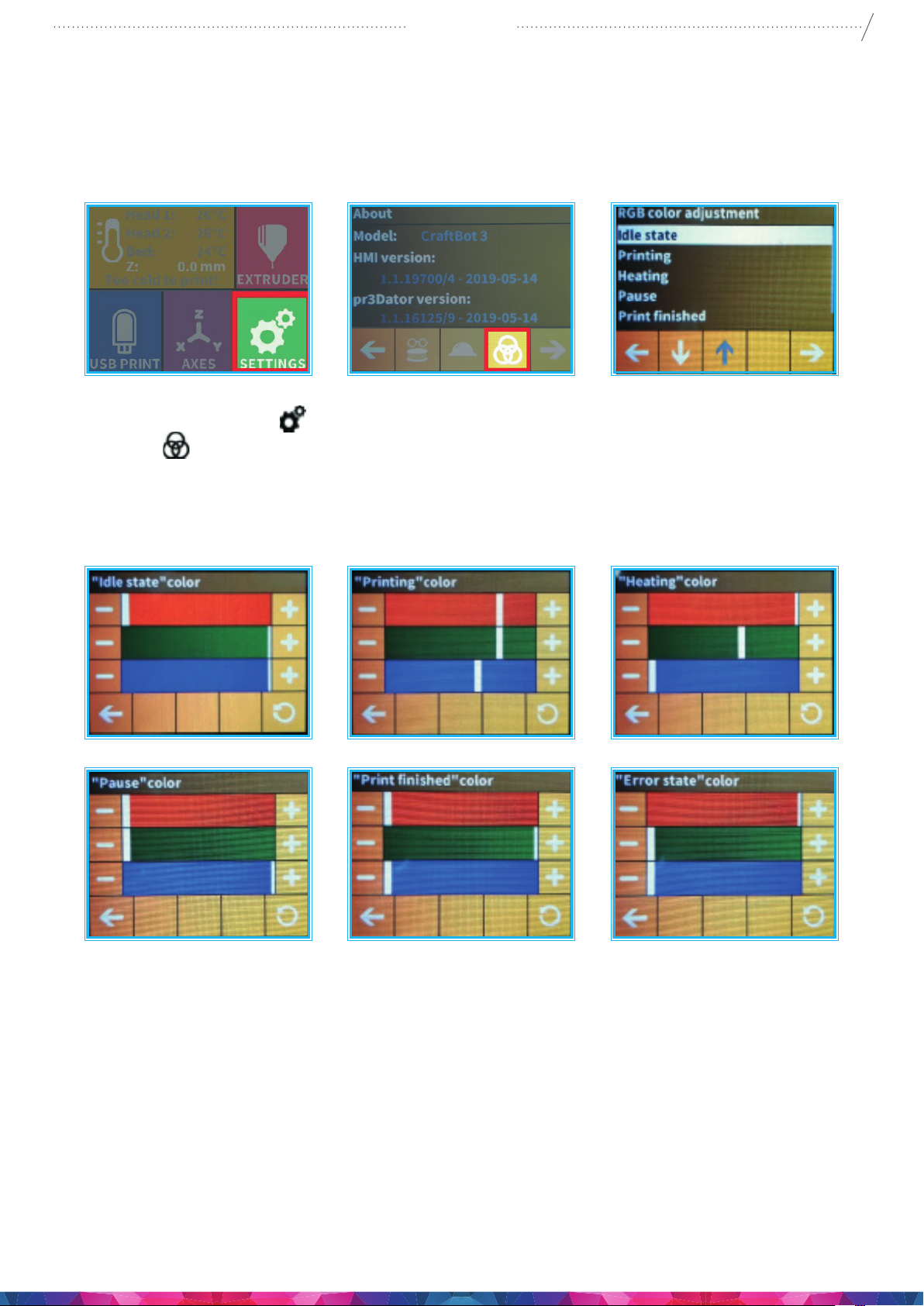
5.4.11. CONFIGURATION OF COLORED RED STRIP
A custom colour can be set for each mode of operation. Modes: idle, printing, heating, pause, print
nished, error
22
1. Select the Settings menu
rings icon
2. The operation modes will appear. You must then decide which you would like to set. Once you have
made a selection, the colour of the operation mode may be set with the help of the RGB colour
sliders and will immediately appear on the LED strip, so the current colour setting will be visible right
away.
.
on the LCD screen and go to the 4th page. Select the three intersecting
Once you have set the desired colour, pressing the back arrow this will save the current settings and
return to the operation modes.
Page 23
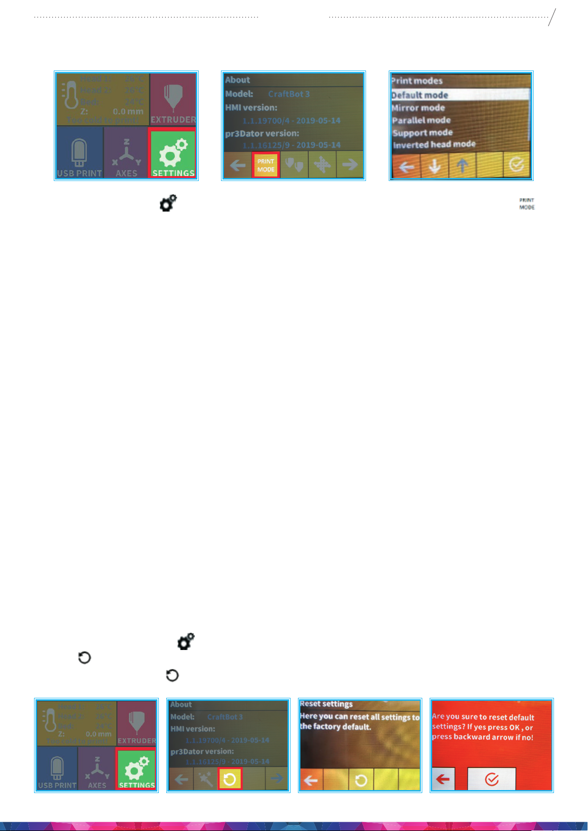
5.4.12. PRINTING MODES
CraftBot 3
23
Select the Settings menu
on the LCD screen and go to the 5th page. Select the Print mode icon
• Default mode: Gcode will determine whether the printer operates with one or two printheads. If an
object was sliced for a single head printer, but contains a support structure, the CraftBot 3 is able to
print the object with normal lament while printing the support with PVA lament. The advantage to
this is that you don’t have to re-slice the existing gcodes if you also want to print with PVA.
• Mirrored printing: If an object ts on half of the build platform, then there is the option of printing
two objects at once which will be mirror images of one another. This way, two objects can be made
in time it takes to print one object. For example, if printing a hand, the printer can make a right and
a left hand at the same time. If a symmetrical object is being created (a heart, for example), both
halves can be printed at once and the entire object can be prepared in the time it takes to print half
an object.
• Parallel printing: If an object ts on half of the build platform, there is the option of printing two
objects at once that will be completely identical. This way, two objects can be made in time it takes to
print one object. The printer’s productivity is therefore doubled.
• Support printing: If a model has been sliced for a 1 headed printer and it contains supports, then
the printer will recognize the supports automatically and will print them with the 2. head. With this
mode you can print supports with soluble material without re-slicing the model.
• Inverted head: It swaps the 2 heads while printing ergo a part what should be printed with the
rst head it will be printed with the second head and vice versa. You do not have to replace the two
laments at the beginning of the print if they are swapped in the two heads
• Backup: It can be used when you print with 1 head. While printing, if the rst head jams, the second
head will continue automatically thus the print won’t stop. When using this mode it is recommended
to use the same lament (or at least the same color) in both heads so there won’t be any dierence
on the nal printed model.
5.4.13. RESET SETTINGS /YOU CAN RESET ALL THE PRINTER SETTING/
1. Select the Settings menu
icon
2. Select the circle arrow
.
on the LCD screen and go to the 6th page. Select the Reset circle arrow
, and press OK.
Page 24
CraftBot 3
6. NAVIGATE THE BUILD PLATE
AND THE EXTRUDERS
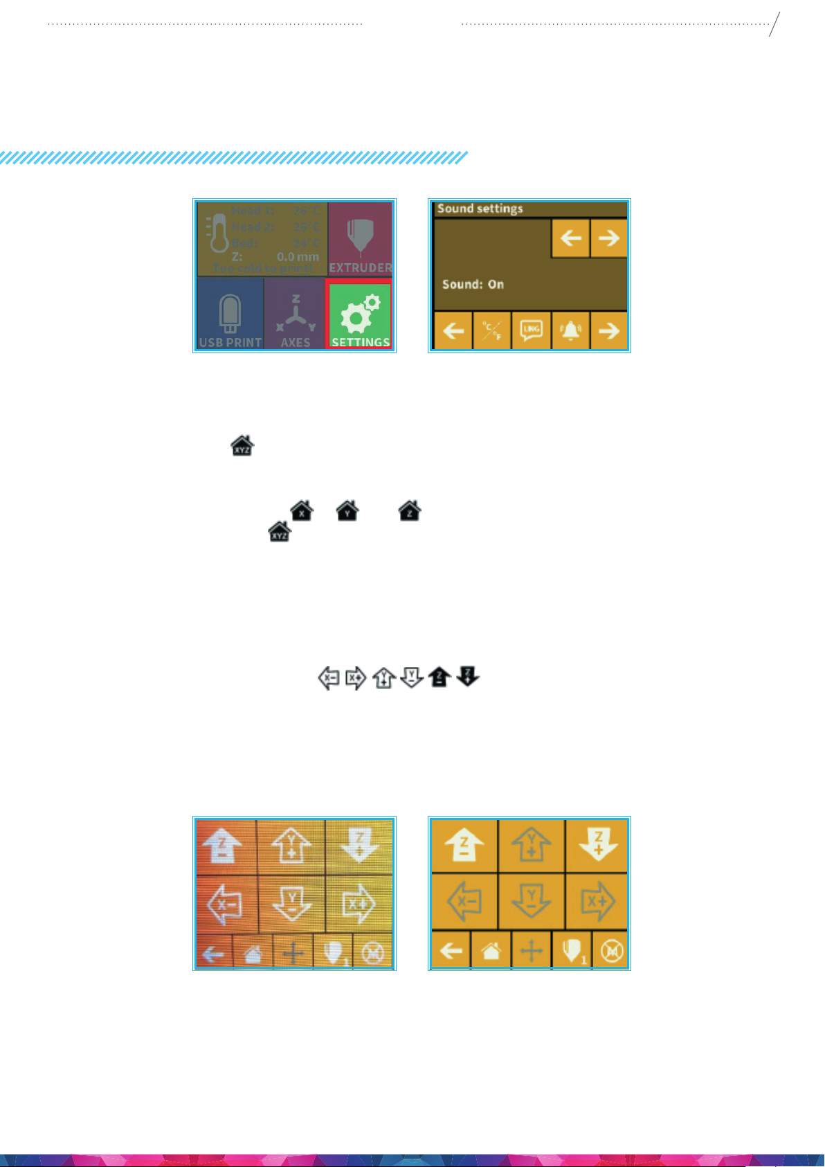
Select the AXES on the menu.
The rst “grey” button will, of course, return you to the main menu.
24
• The small house icon indicates the „home” position of the extruders which is this location the
front corners of the build plate.
• You can reset the extruders and the build plate to the “home” or “zero” position. You can either
set each axis one at a time (X
appropriate Home button
motors of each highlighted icon are engaged.
• To disengage the motors, click on the icon in the far right bottom corner (M with an X through it),
and you will see all of the house icons turn grey. The motors have now been disengaged and you
can freely move the extruders by hand if you wish to do so.
• The directional button to the right of the “home” button can be used to move along the X, Y or Z axis
using the motors. After clicking on this button you will be redirected to another display in which you
will see six dirent arrow buttons
all of the motors are already activated and the house icons are all white. If the house icons are grey,
then nothing will happen. In this case, after clicking on the direction button, you will see all of the
arrows in the color grey. To activate the motors, return to the “home” icon and home in; the house
icons will now turn white and you can go on to the direction display and move the extruders and
bed as you see t.
, Y or Z ), or do all three of them at once by touching the
. If the individual house icons are white, then this means that the
. Note that this option can only be used if
Page 25
CraftBot 3
7. USING THE PRINTER
7.1. USING CRAFTWARE TO CONVERT 3D DESIGN INTO PRINTING COMMANDS
To print a 3D object, CraftBot needs toolpath information generated from 3D object les like .obj or .stl.
Toolpath information is simply called “gcode”. CraftWare software converts 3D designs into printing
commands for the CraftBot 3D printer. CraftWare has been developed by CraftUnique with the aim of
easing and perfecting the printing process.
1. Download the CraftWare slicer software
• Open a new browser session on the computer where you’d like to install CraftWare.
• Go to www.craftunique.com/craftware.
• Scroll down the page to select the latest version of CraftWare
• Select the Windows or MAC/OSX version according to your operating system.
• Download the installer.
• Open the installer and follow the directions to install the software.
2. Open the CraftWare software
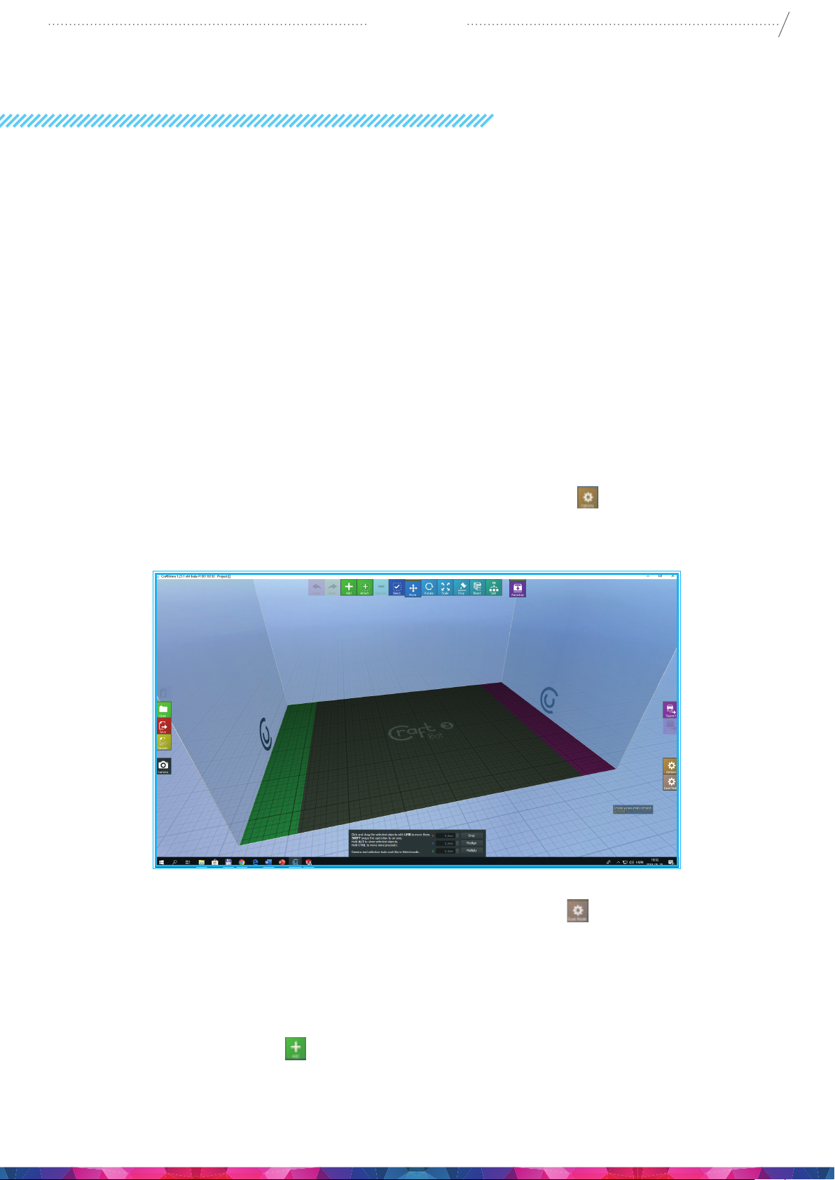
• Once CraftWare has been opened up, you will see a virtual build platform which represents
your CraftBot’s real build plate. Please click on the Options button
3 Printer under the Printer tab page. You can add objects, .stl, .obj les onto this virtual build
plate and get an impression of what the real life print will look like before Printing.
, and select your CraftBot
25
2. Select your desired Dual Head mode By clicking on Dual Mode button
the Dual Head mode. There are four of them:
• Dual Extruder Mode: you can assign an extruder for each object in the project.
• Support Mode: lets you select one of the extruders to create the support bars.
• Mirror Mode: duplicates and mirror the objects, and print them simultaneously.
3. Importing your design objects
• Click on the “Add” button located in the top row of icons. Select the 3D design plan you
want to print from your computer. The selected object will appear at the center of the virtual
build plate. If Dual Extruder Mode is enabled, you can assign heads in the List View under the
Selection tool.
you can change
Page 26
CraftBot 3
4. To generating the toolpath information (gcode) Click on the Slice button to the right side of the
screen. A new screen pops up with options to specify the printing quality and material to be used
along with pages of information on adjustable setting for your model. When you have nished
making your adjustments press the Slice button at the bottom of the setting page.
5. Saving the gcode
• Press the save icon on the side of the Craftware to save the generated Gcode onto a USB drive
then place the USB drive into the top of the printer. Another way is to send information directly
to CraftBot if you are connected via USB cable. The third way is to transfer it via the CraftBot
app application on your phone or tablet. or if you do not have this App you can send the le
using Craftprint App on your computer, you can send the le using the WIFI system directly to
the USB in the top of the printer. For detailed user’s instruction of CraftWare, download the
user manual from https://craftunique.com/docs/craftware-user-manual
7.2. DUAL HEAD PRINTING IN CRAFTWARE
26
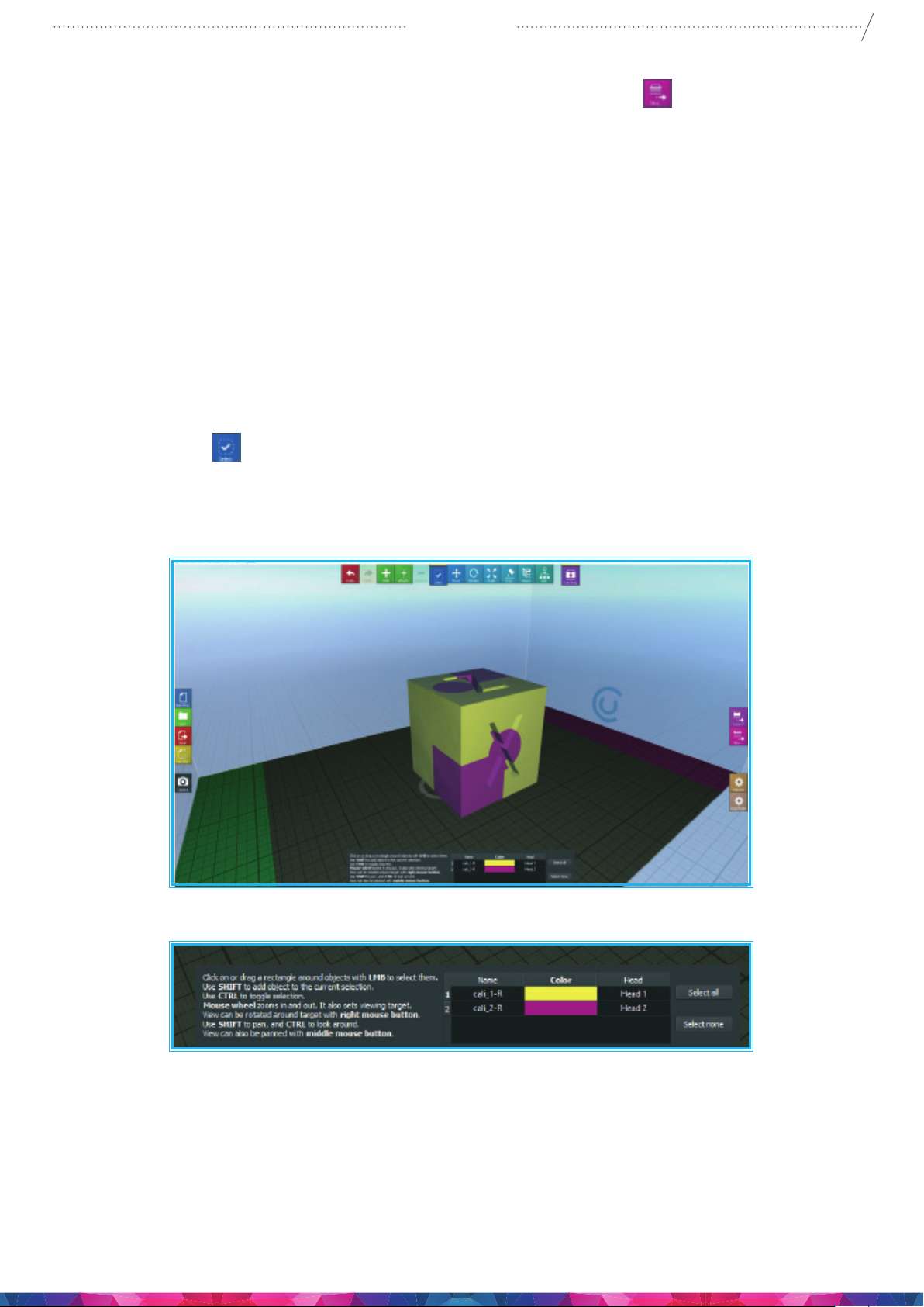
Click the Select icon
the individual selected parts of the print. Select any colour for the individual parts for better viewing by
clicking on the coloured boxes in the settings box at the bottom the screen.
and select a part from assembly. In this menu you can calibrate the heads to
After the Slicing menu you can see the full body.
Page 27
CraftBot 3
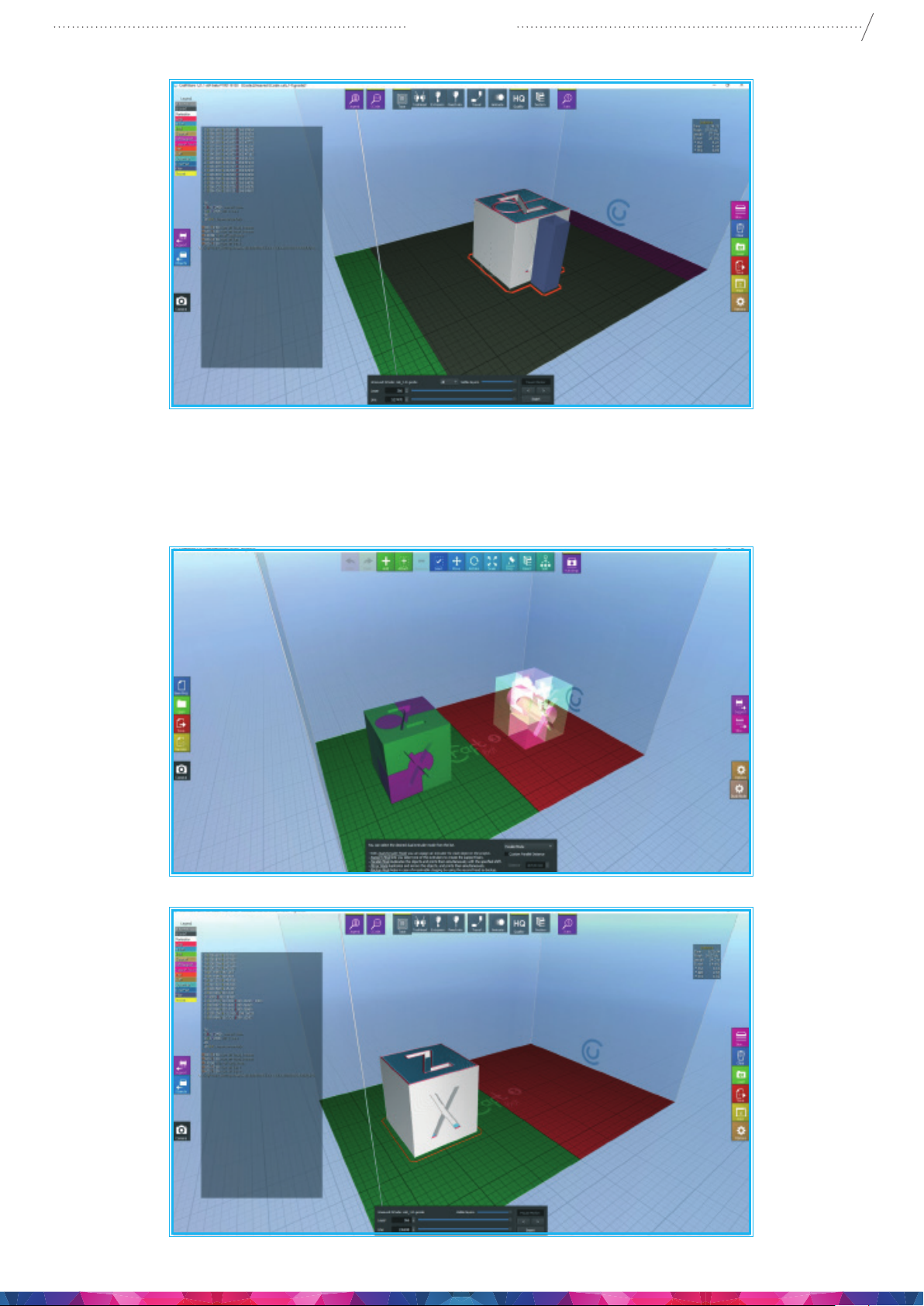
In parallel and mirror printing mode you can see the full body of the model in the left area, on the right
side in the red area is the ghost of the original model. After the Slicing you can see just the body in the
left, but don’t worry about it, it will be printed as well. ( Options to print these duel print modes can also
made on the LCD screen on the printer without using craftware).
27
Page 28
CraftBot 3
7.3. PRINTING OBJECTS FROM USB FLASH DRIVE
1. Save the printing command le created by CraftWare slicer program on a USB ash drive. CraftBot
3 models have Wi-Fi connection and oer the option to upload gcode le using the CraftBot app
mobile application. The Pendrive provided with CraftBot has design samples models already saved
on it. (3D designs models (stl, obj les must be converted into printable Gcode command le with
the help of the CraftWare slicer software.
2. When saved, Insert the USB drive into the USB slot located on the top front of the appliance (above
the LCD screen).
28
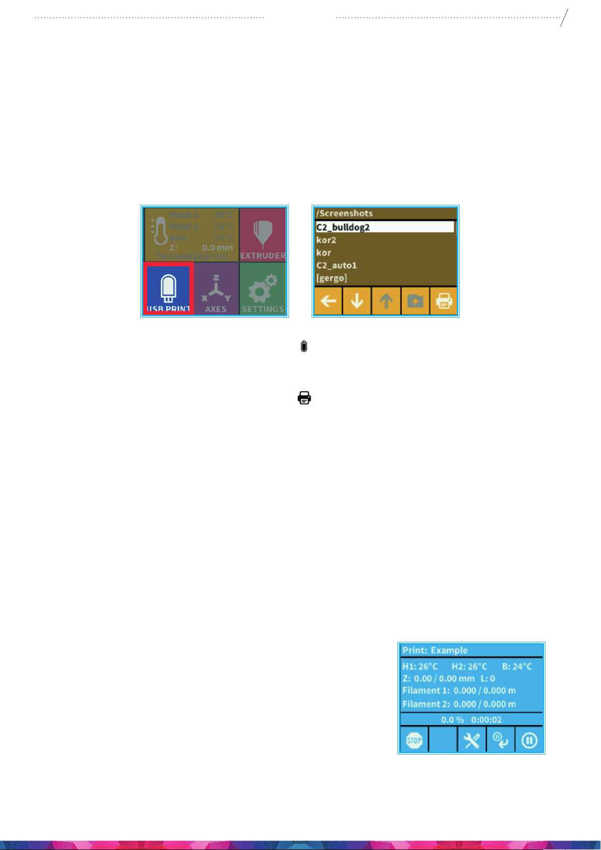
3. Select the USB Print option from the main menu
printing via the CraftBot app application.
4. Scroll down with the arrow to select the object’s le name.
5. Push the printer icon in the bottom right corner
6. The appliance will heat up the extruder/s and the build plate to the desired heat setting in the
Gcode.
7. Printing will only start if the required operational temperature has been reached – until then you
will see the in-print screen, with the status message: ”Heating”with the H1, H2, B marked in red
until the desired heating temp has been reached.
8. During printing, the status of the print is displayed on the LCD screen, indicating progress, based
upon a percentage of the print completed.
9. Please make sure that you have enough lament for the selected project. The quantity is
precalculated by CraftWare in a small window box top right of the screen after slicing the model.
10. After the object has been printed, remove the build plate. and let it cool to avoid burns. The
Printed object can be removed by gently pushing it aside with one hand while holding onto the
printing plate with the other one.
7.4. IN-PRINT ADJUSTMENT
. CraftBot 3 users have the option to initiate a
.
During printing CraftBot displays the following information:
• Name of the le/object to be printed
• Head 1 & 2 and bed temperature
• Z position information
• Filament remaining/total
• Time elapsed/total
There are four options available from this menu: Stop, setting, Pause next layer, Pause
(in order from left to right)
Page 29
CraftBot 3
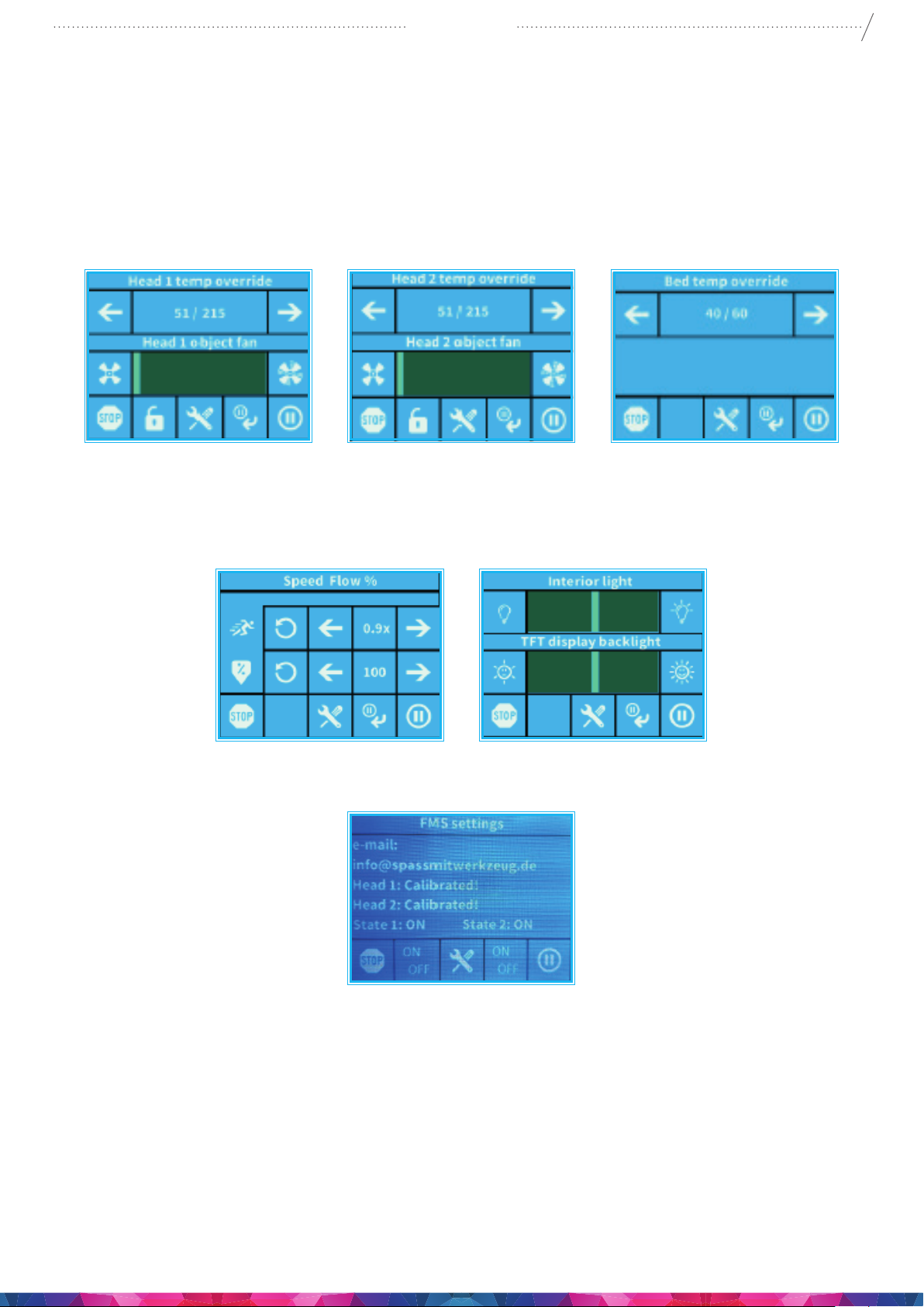
7.4.1. TWEAK FUNCTION MENU
Setting function enables to change temperature, print speed, extrusion ratio, lighting, object fan control
settings.
The in-print tweaks overrule the settings in the gcode.
Temperaturemodication:Heads and bed temperature can be changed, with heads object fans. Set
the speed of the object fan. By default it is unlocked. If locked gcode can’t overwrite setting information.
29
Flowmodication: Print speed and extrusion volume can be modied in percentage ratio to the
original. Use the reset button to change back the values of the gcode.
Light settings: Lighting within the appliance and the display backlighting can be changed
FMS settings: The lament monitoring system observes the lament ow during printing.
7.4.2. PAUSE NEXT LAYER MENU
Pause next layer function will stop printing at the end of the current layer. Once the layer is nished,
CraftBot will switch to Pause menu. This is a toggle button – when the icon is crossed out, it means
that Pause Next Layer function is active. If pushed before the layer is nished it will continue printing
uninterrupted.
Page 30
CraftBot 3
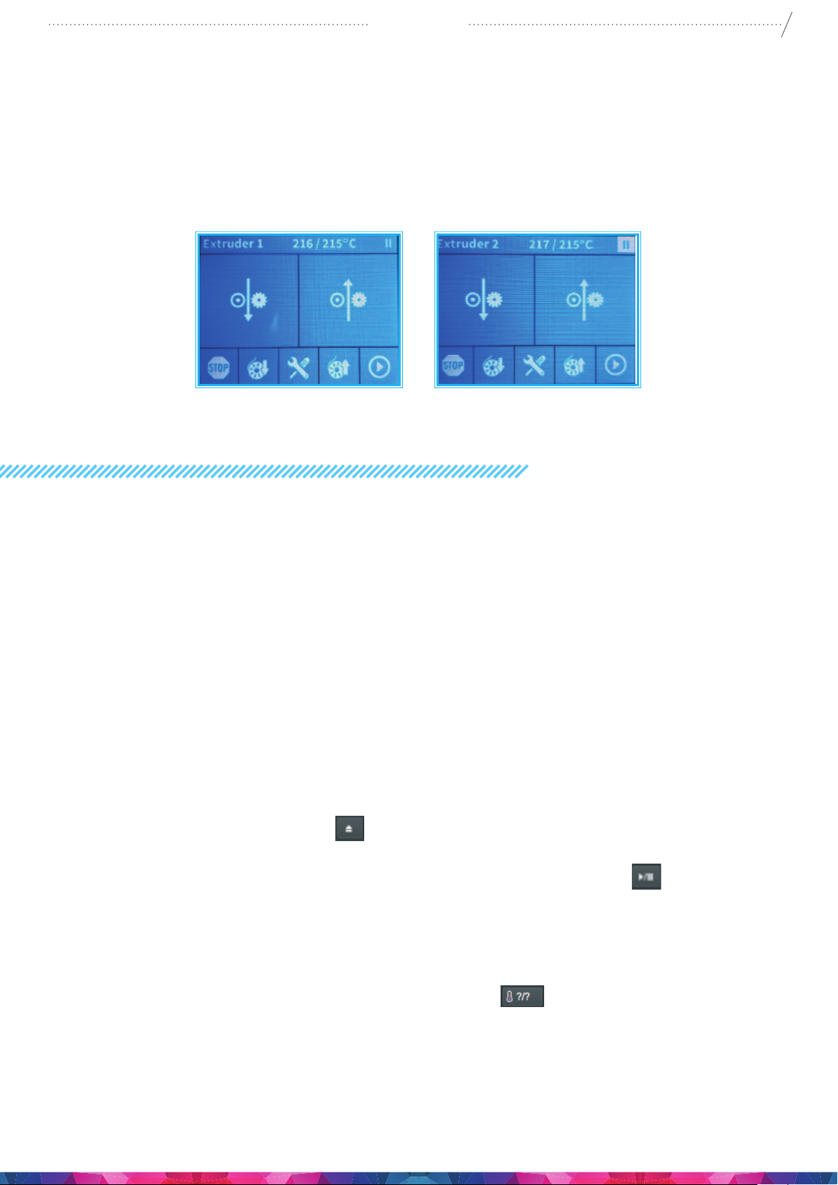
7.4.3. PAUSE MENU
In Pause menu users can change lament, continue printing or terminate the printing project. Pushing
the Play button will continue the printing. For lament change use the Extrude/Reverse functions or the
preprogrammed Load/Unload options. For terminating the printing select “STOP”. CraftBot will ask for a
conrmation. If you pressed the stop button accidentally, you can press the back button to continue the
printing process..
30
8. MOBILE APPLICATION
8.1.USINGCRAFTWARETOCONVERT3DDESIGNINTOPRINTINGCOMMANDS
1. To Installing the CraftBot app and connecting to CraftBot 3
• Download the CraftBot app from the App Store or Play Store and open it.
• Make sure that your CraftBot 3 printer is switched on and connected.
• The app will search for your CraftBot 3 in its reach (if there are more, it will nd all your
printers and you can select your CraftBot 3 to connect to from the list)
• Select and connect to the printer and you will be directed to the main screen.
2. To Uploading a gcode to the USB placed in the CraftBot 3
• Select one of the gcodes on the main screen or select the gcode le saved on your mobile
device
• Conrm the le selection – upload
• Once 100 % of the les has been transferred, close
3. Initiating printing via the CraftBot app
• Select “Print” on the main menu
• Select one of the gcode les and uploaded onto the USB storage in the CraftBot 3
• Conrm the Gcode le you want to print from selection in the play/pause button.
• You can track the progress of printing on screen
• Printing can be stopped or paused
• Once 100 % of the les has been transferred, close
4. Changing the CraftBot 3’s heat settings via the Craftprint application
• From the icons in the main menu select “Heat Settings”
• You can choose between settings for PLA, ABS, PET or you can set the head and bed
temperature settings according to the printing model needs.
App Settings Users can specify how the heat and unit setup information is displayed (Celsius/Fahrenheit,
Metric/Domestic)
Page 31
CraftBot 3
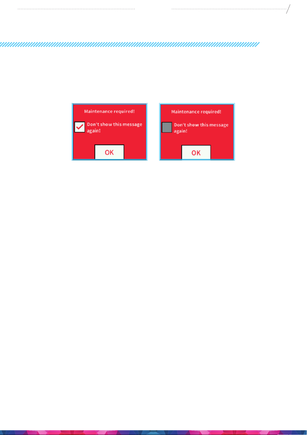
9. CLEANING AND MAINTENANCE
IMPORTANT!
Cleaning and lubrication should only be conducted while the extruder and built plate are cold. Please
allow the CraftBot 3D printer to cool down at least 30 minutes before cleaning or maintenance. It is
necessary to clean the printer after every 1000 hour. After every 1000 hour we need to replace any worn
the used parts on the printer. The printer will automatically send a warning to the user with a message
like the one in the picture.
31
CLEANING
Clean the metal housing of the CraftBot by wiping with a damp cloth.
Cleaning the build plate Remove the build plate by unscrewing the 2 white screws located in the front of
the plate. Clean the plate with window cleaner/ Acetone. Wipe clean with a dry cloth or paper towel.
LUBRICATING
The CraftBot printer should be lubricated at least once after every 50 hours of use or every 6 months.
depending on the working hours. Problems can occur and print quality can be lost if maintenance is
ignored.
Tools needed for lubrication:
• PTFE based spray lubricant or white lithium grease. make sure to have a thin straw on the
spray tin to reduce overspray, and spraying directly onto the desired parts.
• 2 separate lint-free rags or thicker stronger paper towels
• Personal protection such as gloves and safety glasses/goggles
• lighting to see the interior of the CraftBot correctly (lamp)
1. Move the build plate and the extruder to the „Home” position.
2. Once the extruder and bed are in the home position, turn the CraftBot printer o and unplug it
from the electrical outlet.
3. If you look beneath the build plate you will see three rods that run vertically in which the build
platform moves up and down on. The two outside rods are smooth and the center rod is
threaded. These three rods are known as the “Z-axis rods”.
4. Place a folded paper towel or a lint-free rag behind the center rod. This rag is used to protect
other areas of the printer from any overspray that may occur.
5. LUBRICATE ONLY THE PARTS RECOMMENDED IN THIS MANUAL!
6. Spray the threaded Z-axis rod at a relatively close distance to reduce overspray. Make sure the
lubricant reaches the inside of every thread (if using grease, spread with hand wearing gloves).
7. Make sure not to over lubricate, spray only the minimum required amount from top to bottom!
8. Do not spray the other two rods directly! Spray the Paper towels rst and wipe it onto the rods.
Page 32

CraftBot 3
9. Remove the rag from the CraftBot interior.
10. Plug in and power up the CraftBot and move the build plate to the lowest point. (enter the“Axes”
menu, home position and then go to the directional menu and press the Z down arrow until the
bed reaches the lowest point).
11. Turn the CraftBot printer o and unplug it from the electrical outlet.
12. Place a second clean rag on top of the heated build plate to protect the components and Kapton
from any overspray.
13. Repeat the process for the top side of the Z-axis rods the same as you performed on the bottom
half: placing a protective rag/ paper towel behind threaded rod. spray, & wipe any excess lubricant
on other two outside rods.
14. Power up the CraftBot once again. Press the home button in the Axes menu to raise the build
plate back up to the highest position.
15. Turn the CraftBot printer o and unplug it from the electrical outlet.
16. Wipe any excess lubricant o from the bottom side of the Z-axis rods and bearings.
17. Power up your CraftBot once again and move the build plate back to the lowest point.
18. Turn the CraftBot printer o and unplug it from the electrical outlet.
19. Wipe any excess lubricant o from the top side of the Z-axis rds and bearing.
20. Power up the CraftBot once again and raise the build plate back up to the highest position.
21. Turn the CraftBot printer o and unplug it from the electrical outlet. The motors will now
disengage so that you can move the extruder freely by hand.
22. Use an oiled rag to lubricate the X and Y linear rails. Do not spray from above! Move the
extruders back and forth by hand to both extremes of the axes. When the extruders moves
absolutely smoothly you are nished.
32
10. TROUBLESHOOTING
10.1. PREVENTING/ FIXING A CLOGGED EXTRUDER
The number one inconvenience that you will run across when 3D printing is clogging of the extruder.
But we have good news for you! This problem can be easily avoided by following a few simple rules of
“3D printing etiquette”.
• First, always wait until the extruder and heated build plate are fully heated to their maximum
intended print value before inserting the lament. Inserting the lament at a lower temperature is
just asking for a clog.
• On the side of the Extruder assembly is a pressure leaver that you can adjust the pressure
the Bearing that pushing the lament onto the Extruder gear wheel. make sure this et to max
pressure.
• When unloading or changing the lament: always heat up all the way rst and then “extrude” for 5
seconds and immediately press “reverse” aiding the lament retrieval by pulling a little bit on the
lament end coming out from the extruder with your hand.
• It is especially important to clean out as much old leftover lament between using a dierent
lament, as the dierent characteristics of the laments may cause problems. Problems
may occur from even printing the same material in a dierent color, can cause clogs from
inconsistencies in the laments. For example: you must heat up to 250°C to clear out any extra
ABS left behind before using PLA which melts at much lower temp than ABS.
Page 33

CraftBot 3
Clogging is the most common problem in every 3D printer and cannot be prevented 100%, but if you
follow these simple steps you will prevent 95% of occurrences. If you still cannot clear the passage
with just this method, you may want to move onto the next method by following these next steps to
actually remove the nozzle itself…
10.2. REMOVING THE NOZZLE
On the original Craftbots before the CB3 you was able to push out old lament from the top of the
Extruder but with the CB3 this is now no longer an option. So your option is to now to do this operating
from the bottom of the extruder up from the Heat block.
To clean out the extruder properly by removing the nozzle from the heat block. You will need to
disconnect the fan assembly rst. To remove this entire piece by unfastening the four bolts connecting it
to the outside of the extruder assembly. Take care of the delicate connections as you slide the Fan case
forward from the Extruder.
You will need to remove the nozzle while the extruder is heated up to 250°C. Now, using both a 7mm
Plus a 20mm wrench (from the provided Nozzle kit box). Use the 20 mm wrench to hold the heat block
and keep it from moving this is located under the red silicon cover. Now with the 7mm wrench (not
provided) start to remove the nozzle itself from the hot heat block. Make sure to use an oven mitt to
protect yourself from burns. Also Please make sure that none of the wires are disconnected While
removing the nozzle. You can unclog the nozzle tip with a pin. Or just simply replacing it with a new one
to save time. It is at this point in time while the Nozzle is o you can use the 2mm Allen Key Wrench to
push up any old lament still left in the extruder tubes.
All new Printer Hotends.
Newer mark 2 Nozzles are now in production, that are available from Craftunique these are designed
to stop any clogging, from happening with longer length nozzles. This comes with a new heat block and
silicon cover to give better temperature control plus a new heatsink with new size screws to hold the
newly designed tungsten Heatbreak. All these do come as standard with our new printers.
If you have the older printers and you nd that you have the original hotend assembly and you would
like to change this for a new upgrade parts, then these are available from the Craftunique webshop.
Just remember the new hotends parts, are not compatible with the older hotends. So you will need to
purchase a complete new hotend assembly.
33
Page 34
CraftBot 3
11. FIRMWARE UPDATE
11.1. FIRMWARE UPDATE WITH SOFTWARE
Updating the rmware adds new function(s) and improves performance.
CAUTION: NEVER turn OFF the computer or disconnect the USB cable while updating the rmware.
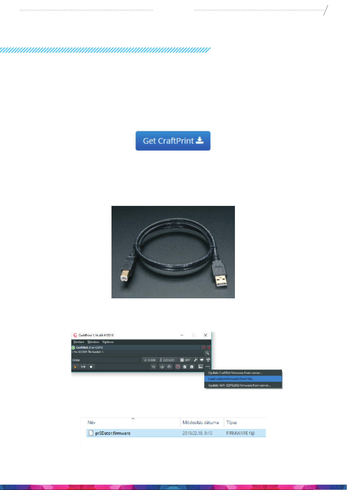
1. Download CraftPrint® software from Craftunique® website: https://craftbot.com/craftware/
2. Install the CraftPrint® application on your computer.
3. Download the pr3Dator® rmware le from Craftunique website and extract the ZIP le on your
computer. Please read the attached Release Notes. https://www.craftunique.com/rmware
4. Connect the printer to your computer with USB cable.
34
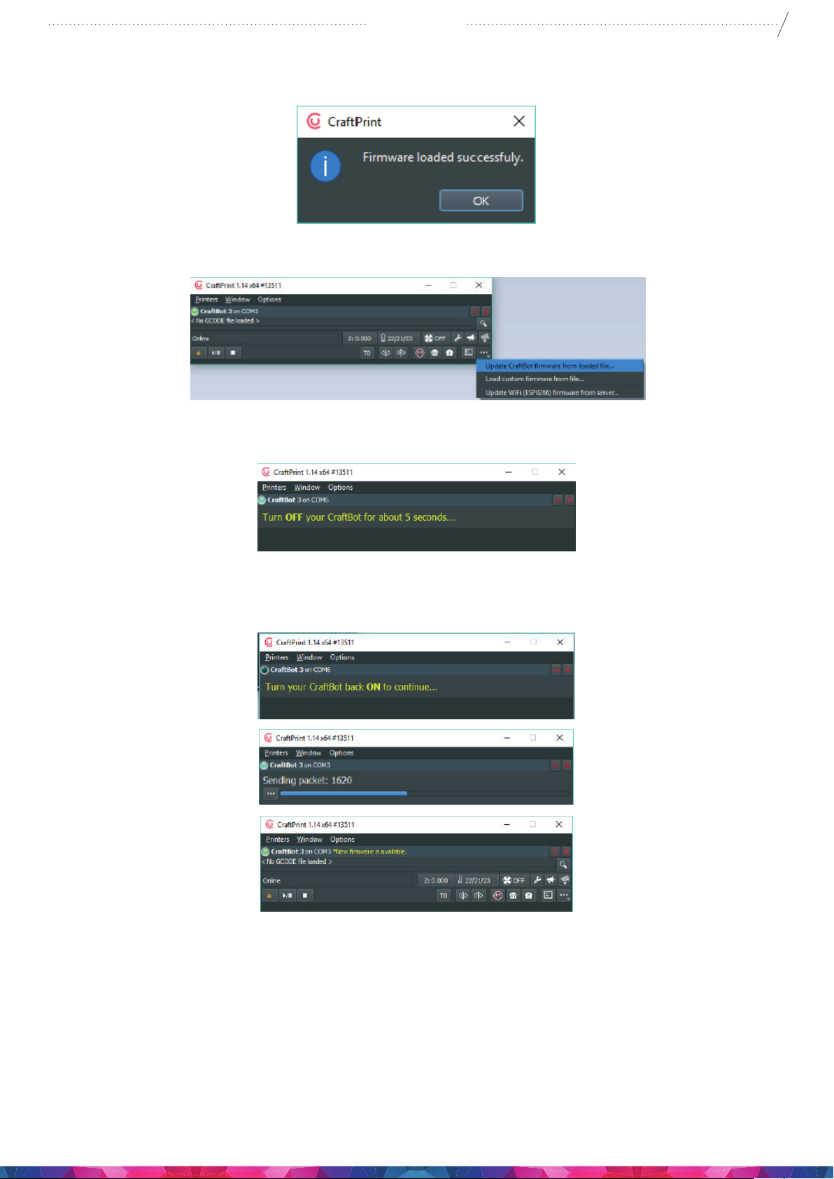
5. Open the CraftPrint program.
6. Select the „Load custom rmware from le” from „ …” menu
7. Select and open the *.rmware le
Page 35
CraftBot 3
8. On successful load you will get a conrmation message, click OK!
9. Open again the “…” menu and select Update CraftBot rmware from loaded le…
35
10. When asked please turn o the printer at least 5 seconds.
11. Turn the printer back on and wait until the update nished
12. When the update has nished, power cycle the printer once again. (o/on) and Check the pr3Dator
rmware version on the printer LCD screen, select > settings icon and go to the 1st page.
13. Update is done.
Page 36
CraftBot 3
11.2. FIRMWARE UPDATE ON OLDER PRINTERS
If you have an older printer and update it a long time ago the rst need to restart your printer. Follow
the next easy instructions and update your Firmware.
From time-to-time you may encounter a trac jam scenario when attempting to upload this new
rmware; in some cases your CraftBot’s screen will go completely blank and even seem to be
nonfunctional… but do not worry! This situation can be easily remedied by following these easy steps to
x this problem.
Take a look at your LCD display located at the middle top front of the CraftBot 3D printer. You will need
to get around to the back of the LCD HMI board to nd erase button. The „erase” button is located on
the bottom right corner of the LCD or on the left. Switch o your machine. Wait 10 seconds. Press and
hold the „erase” button on the HMI board, while powering up your printer again. Wait 5 seconds, and
switch o your printer again and release the erase button.
Main PCB board
To erase the controller PCB Board, while your printer is still switched o, use a piece of lament to
insert into the „erase” hole which is located on the right side of the printer, under the USB / Encoder
connectors. Press and hold the button ( you should feel and hear a click as you push in this switch) with
the lament, while powering up your printer again. Wait 5 seconds, and switch o your printer. Now
both controller boards are erased. At this point the screen should still be blank and your CraftBot should
still be unresponsive. From this point proceed to the rmware update mentioned previously and after
uploading you should have a 100% operational CraftBot 3D printer again!
36
12. APPLYING A NEW LAYER
OF PROTECTIVE KAPTON
SHEET TO YOUR BUILD PLATE
Build plate Kapton sheets can get worn out over time, or it can be damaged by the nozzle due to
incorrect leveling. Reapplying a new Kapton sheet is essential to maximize print qualities if the old one
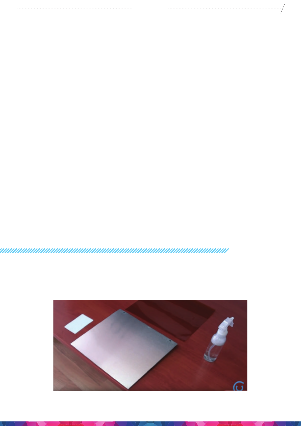
has issues. To reapply a new Kapton sheet, take the build plate out of the machine and remove the old
sheet by striping it o of the aluminum plate. Clean the surface of the aluminum plate with acetone.
Page 37
CraftBot 3
Remove the protective sheet from the new Kapton sheet then apply some window cleaning liquid onto
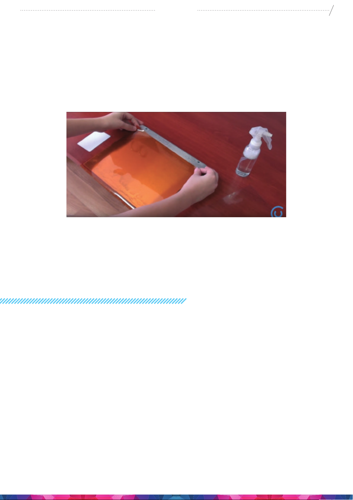
the stick surface of the New sheet, then spray the liquid onto the clean surface of the aluminium build
plate. Place the sticky side of the new sheet onto the plate. the access liquid will help you to position the
new sheet correctly.
Align the Kapton to the front edge of the aluminium plate (the side where the screws stick out). Once
the Kapton sheet is positioning correctly onto the plate, Place the protective sheet (which was removed
originally ) onto the top surface on the new Kapton sheet this will help to prevent any scratches or
damages during the squeezing out process of the remaining liquid from between the plate and the
sheet with a thin but solid object, like an unused credit card..
37
Start from the center of the plate and move horizontally and vertically. Once all the liquid has been
squeezed out and the sheet is applied properly, put the plate somewhere to dry. Allow the sticky part to
rest for 1 day before using giving time for the glue to set.
13. USEFUL THINGS
13.1. G AND M CODES
14.- G1: Linear move: E F S X Y Z
15.- G0: Linear move: E F S X Y Z
16.- G2: Draw lin arc: E F I J U X Y
17.- G3: Draw lin arc: E F I J U X Y
18.- G4: Dwell: P S
19.- G20: Set units to inches.
20.- G21: Set units to millimeters.
21.- G28: Move to origin: X Y Z
22.- G69: Random XY Killer: L Q S U V X Y
23.- G90: Set to absolute positioning.
24.- G91: Set to relative positioning.
25.- G92: Set position: E S X Y Z
26.- G100: Linear move: E F X Y Z
27.- G101: Relative linear move: E F X Y Z
28.- G102: Relative linear move width timeout: E F S T X Y Z 29.- G103: Clear timeout: S
Page 38

CraftBot 3
30.- G104: Extrude width timeout: E T
31.- G195: Reset motion.
32.- G196: Reset all.
33.- G197: Pause.
34.- G198: Resume.
35.- G199: Imadiate pause.
36.- G194: Imadiate abort.
37.- M18: Disable stepper motors.
38.- M82: Set extruder to absolute mode.
39.- M83: Set extruder to relative mode.
40.- M84: Stop idle hold: S
41.- M8484: Motors o imadiate: S
42.- M105: Get temperature of extruders and bed: P T 43.- M106: Turn cooling fan on: S T
44.- M116: Turn cooling fan on: H L S T
45.- M104: Set extruder temperature: Q S T
46.- M109: Set and wait head temperature: Q S T 47.- M1400: Start heating and waiting: B E H P Q T
48.- M107: Turn cooling fan o.
49.- M110: Print Start or Stop: S
50.- M114: Get current position.
51.- M115: Get rmware version.
52.- M117: Display message.
53.- M140: Set bed temperature: H L S
54.- M190: Set and wait bed temperature: S
55.- M220: Set speed override percent: S
56.- M221: Set extrusion override percent: S
57.- M300: Play beep sound: P S
58.- M424: ...: E F
59.- M423: ...: E F T
60.- M422: Start Head Preparation.
61.- M425: Set nozzle wipe position: S
62.- M430: Head change ZHop settings: F Z
63.- M431: Head change Exit Retract settings: E F
64.- M432: Head change Enter Retract settings: E F
65.- M433: Head change Enter Prime settings: E F
66.- M450: Self test: E F
67.- M900: Linear advance beta version: A D K
68.- M905: Set feed High/Low: H L
69.- M73: M73 progressbar refresh: P S
70.- M1001: Get Printer Version.
71.- M1002: Get unique ID: S
72.- M1003: Get rmware version: S
73.- M1004: Get HMI version.
74.- M1005: Get HMI board version: S
75.- M1006: Set limits s=1 Case / S=2 Head: H L S T
76.- M1014: Get ADC values: S
38
Page 39

CraftBot 3
77.- M1015: Get PWM duty.
78.- M1020: Puer mode: S
79.- M1104: Get Info: P
80.- M1105: Get HMI mode.
81.- M1106: Set HMI mode.
82.- M1114: Get machine coordinates.
83.- M1115: Get queue.
84.- M1116: Set Min Q: Q
85.- M1123: Set T7 pin high or low: S
86.- M1160: Fan control (Case,Dome,Head,Obj): C D H O T 87.- M1161: Fan override: S
88.- M1200: Set feed properties: F H L
89.- M1202: Set axis soft limit: E X Y Z
90.- M1203: Set XY acceleration: A D F
91.- M1204: Set Z acceleration: A D F
92.- M1210: Set extruder correction: F K
93.- M1211: Set extruder correction: F K
94.- M1212: Set thermal runaway: Q S
95.- M1297: Mem dump: S
96.- M1298: Send command: S
97.- M1299: Queue report: S
98.- M1300: Set extruders PID: D F I P W
99.- M1301: Set bed PID: D F I P W
100. - M1401: Seat head heating curve: D Q
101. - M1402: Seat bed heating curve: D Q
102. - M1403: Flush.
103. - M1800: Set HMI Baud: S
104. - M1885: Set G1 counter: S
105. - M1886: Read restart data.
106. - M1887: Read startup GPBR.
107. - M1888: Backup: Q S
108. - M1889: Set RTC: D S
109. - M2001: Set max imp: E X Y Z
110. - M2002: Set ref imp: X Z
111. - M2003: Soft Enable encoder: S
112. - M2004: Enable encoder check: S
113. - M2005: Set encoder div: Q S
114. - M2006: Set encoder calibstate: S
115. - M2007: Encoder autoset: S
116. - M2008: Set encoder params: Q S
117. - M3000: Get X Y Z jupers states: J X Y Z
118. - M3001: Set LED szalag: L
119. - M3002: Set LCD light: L
120. - M4001: Set heating overlap: P
121. - M4003: Set maximum head heat temp: H S
122. - M4004: Get heat state: S
39
Page 40

CraftBot 3
123. - M4005: Set maximum bed heat temp: H S
124. - M5000: Set XY Z jog feed: X Z
125. - M5001: Set mechanical parameters: E X Z
126. - M5002: Set XY oset: X Y
127. - M5003: Set TMC2130 current: E X Y Z
128. - M5004: Get TMC2130 status regiter.
129. - M5005: XY calibration moode: S
130. - M6666: Reset: S
131. - M6969: Erase ash: S
132. - M7001: Set WIFI SSID/Pass.
133. - M7002: Wi List AP First.
134. - M7003: HMI send WIFI AP list.
135. - M7004: WiFi Report: Q S T
136. - M7005: Set e-mail address.
137. - M7006: Get AT version number.
138. - M7007: Rec WiFi AT version.
139. - M7008: Overwrite Wi-Fi SSID.
140. - M7009: wi reset pin check: S
141. - M8001: Read motor: Q S
142. - M8010: Read errors.
143. - M8020: Set thermal motor warning: S
144. - M9001: Set LED to function.
145. - M9003: ReadMotorDIAG.
146. - M9005: Enable/disable cover: S
147. - M9006: Set print mode: Q S X
148. - M9007: Switch o calculation.
149. - M9008: Set nozzle diameter: D T
150. - M9090: Set parser limits: S X Y Z
151. - M9999: Set MicroStep: E X Y Z
152. - M765: calc oset.
153. - M766: Meas x y distance: D T
154. - T0: Select tool 1: F S X Y Z
155. - T1: Select tool 2: F S X Y Z
40
13.2. USEFUL LINKS
User Manuals: https://support.craftunique.com/258569-User-manuals
Firmware: https://craftbot.com/rmware
Youtube ocial channel: https://www.youtube.com/channel/UC04qcXksuyJ2GASsGscNqpA/featured
Page 41

CraftBot 3
14. GUARANTEE
For special conditions relating to product guarantee, see the „Guarantee Statement” on a separate
sheet, delivered with the product as well.
15. LIMITATION OF LIABILITY
With the exceptions included in the regulations concerning the guarantee and to the greatest extent
permitted by the relating act, CRAFTUNIQUE Ltd. is not responsible for any direct, indirect, specic,
stochastic or consecutive damage claims which are stem from the breaching of the terms of guarantee,
respectively any other legal theory, included, but not limited to
• the loss of usability
• the loss of income, the loss of actual or expected prot (including the prot from contract), the loss
of expected savings, loss of business, loss of opportunity,
• the loss of a fair name and injury to a fair name,
• the loss, injury or perishing of data,
• any indirectly or consecutively caused damage or loss, including the damage caused by the changing
of equipment/installation or property, respectively
• the cost of the restoration or reproduction of data stored or used on the Product.
41
The restriction above does not refer to CRAFTUNIQUE Ltd.’s legal liability for intentional, serious
negligence and/or default. Certain jurisdictions do not allow the exclusion or limitation of accidental
or consecutive damage, therefore if such jurisdiction regulates the guarantee, the restrictions above
does not refer to You.
 Loading...