

Page 1

Owner's Manual
ELECTRIC START
42" MOWER
6 SPEED TRANSAXLE
LAWN TRACTOR
Model No.
917.270752
• Safety
• Assembly
• Operation
• Maintenance
• Repair Parts
III I III from preV!oUslybuilt engines; Before You Start the engine; read
_ and underotandthla Owner s Manual
CAUTION:
Read andfollowall
Safety Rules and Instructions
before operatingthis equipment.
! : .......... ...................... .....
For answers to your questions
about this product, Call:
1-800-659-5917
Sear,= Craftsman Help Line
5 am - 5 pm, Mon - Sat
Sears, Roebuck and Co., Hoffman Estates, IL 60179
Visit our Craftsman website: www.sears.com/craftsman
Page 2

Warranty ................................................ 2
Safety Rules .......................................... 3
Product Specifications .......................... 5
Assembly ............................................... 7
Operation ............................................ 10
Maintenance Schedule ....................... 17
LIMITED TWO YEAR WARRANTY ON CRAFTSMAN RIDING EQUIPMENT PARTS
For two (2) years from the date of purchase, if this Craftsman Riding Equipment is
maintained, lubricated and tuned up according to the instructions in the owner's
manual, Sears will repair or replace, free of charge, any parts found to be defective in
material or workmanship. Warranty service is available free of charge by taking your
Craftsman riding equipment to your nearest Sears Service Center. In-home warranty
service is available but a trip charge will apply. This warranty applies only while this
product is in the United States.
This Warranty does not cover:
• Expendable items which become worn during normal use, such as blades, spark
plugs, air cleaners, belts and oil filters.
• Tire replacement or repair caused by punctures from outside objects, such as nails,
thorns, stumps, or glass.
• Repairs necessary because of operator abuse, including but not limited to, damage
caused by towing objects beyond the capability of the riding equipment, impacting
objects that bend the frame or crankshaft, or over speeding the engine.
• Repairs necessary because of operator negligence, including but not limited to,
electrical and mechanical damage caused by improper storage, failure to use the
proper grade and amount of engine oil, failure to keep the deck clear of flammable
debris, or the failure to maintain the equipment according to the instructions con-
tained inthe owner's manual.
• Engine (fuel system) cleaning or repairs caused by fuel determined to be contami-
nated or oxidized (stale). In general, fuel should be used within thirty (30) days of its
purchase date.
• Riding equipment used for commercial or rental purposes.
LIMITED 90 DAY WARRANTY ON BATI'ERY
For ninety (90) days from date of purchase, if any battery included with this riding
equipment proves defective in material or workmanship and our testing determines the
battery will not hold a charge, Sears will replace the battery at no charge. Warranty
service is available free of charge by taking your Craftsman riding equipment to your
nearest Sears Service Center. In-home warranty service is available but a trip charge
will apply. This warranty applies only while this product is in the United States.
To locate the nearest sears service center or to schedule in-home warranty service,
simply contact sears at 1-800-4-my-home
This Warranty gives you specific legal rights, and you may also have other rights which
may vary from state to state.
Maintenance ....................................... 17
Service and Adjustments .................... 21
Storage ............................................... 27
Troubleshooting .................................. 28
Repair Parts ........................................ 32
Parts Ordering ....................... Back Cover
Sears, Roebuck and Co., D/817 WA, Hoffman Estates, IL 60179
2
Page 3
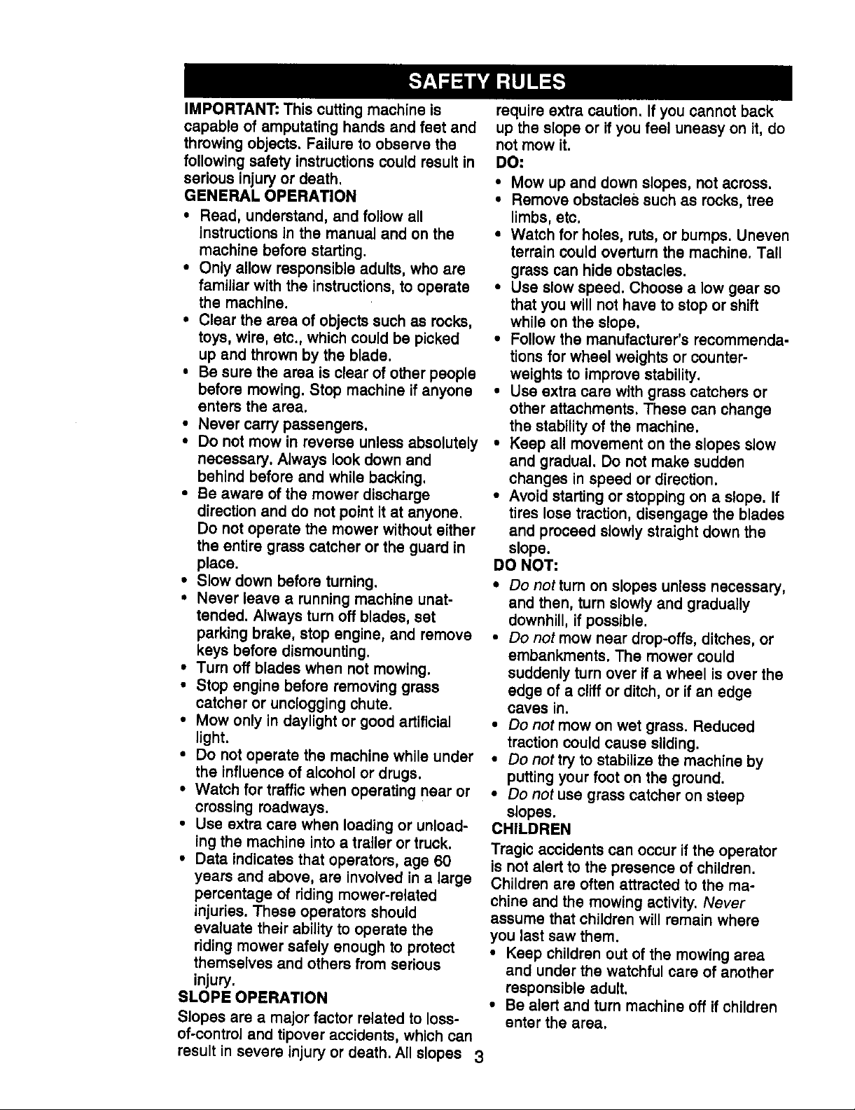
IMPORTANT: This cutting machine is
capable of amputating hands and feet and
throwing objects. Failure to observe the
following safety instructionscould result in
sedous injury or death.
GENERAL OPERATION
• Read, understand, and follow all
instructions in the manual and on the
machine before starting.
• Only allow responsible adults, who are
familiar with the instructions, to operate
the machine.
• Clear the area of objects such as rocks,
toys, wire, etc., which could be picked
up and thrown by the blade.
• Be sure the area is clear of other people
before mowing. Stop machine if anyone
enters the area.
• Never carry passengers.
• Do not mow in reverse unless absolutely
necessary. Always look down and
behind before and while backing.
• Be aware of the mower discharge
direction and do not point it at anyone.
Do not operate the mower without either
the entire grass catcher or the guard in
place.
• Slow down before turning.
• Never leave a running machine unat-
tended. Always turn off blades, set
parking brake, stop engine, and remove
keys before dismounting.
• Turn off blades when not mowing.
• Stop engine before removing grass
catcher or unclogging chute.
• Mow only in daylight or good artificial
light.
• Do not operate the machine while under
the Influence of alcohol or drugs.
• Watch for traffic when operating near or
crossing roadways.
• Use extra care when loading or unload-
ing the machine into a trailer or truck.
• Data indicates that operators, age 60
years and above, are involved in a large
percentage of riding mower-related
injuries. These operators should
evaluate their ability to operate the
riding mower safely enough to protect
themselves and others from serious
injury.
SLOPE OPERATION
Slopes are a major factor related to loss-
of-control and tipover accidents, which can
result in severe injury or death. All slopes 3
require extra caution. If you cannot back
up the slope or if you feel uneasy on it, do
not mow it.
DO:
• Mow up and down slopes, not across.
• Remove obstacles such as rocks, tree
limbs, etc.
• Watch for holes, ruts, or bumps. Uneven
terrain could overturn the machine. Tall
grass can hide obstacles.
• Use slow speed. Choose a low gear so
that you will not have to stop or shift
while on the slope.
• Follow the manufacturer's recommenda-
tions for wheel weights or counter-
weights to improve stability.
• Use extra care with grass catchers or
other attachments. These can change
the stability of the machine.
• Keep all movement on the slopes slow
and gradual. Do not make sudden
changes in speed or direction.
• Avoid starting or stopping on a slope. If
tires lose traction, disengage the blades
and proceed slowly straight down the
slope.
DO NOT:
• Do nottum on slopes unless necessary,
and then, turn slowly and gradually
downhill, if possible.
• Do not mow near drop-offs, ditches, or
embankments. The mower could
suddenly turn over if a wheel is over the
edge of a cliff or ditch, or if an edge
caves in.
• Do not mow on wet grass. Reduced
traction could cause sliding.
• Do not try to stabilize the machine by
putting your foot on the ground.
• Do not use grass catcher on steep
slopes.
CHILDREN
Tragic accidents can occur if the operator
is not alert to the presence of children.
Children are often attracted to the ma-
chine and the mowing activity. Never
assume that children will remain where
you last saw them.
• Keep children out of the mowing area
and under the watchful care of another
responsible adult.
• Be alert and turn machine off if children
enter the area,
Page 4
• Beforeandwhenbacking, look behind
and down for small children.
• Never carry children. They may fall off
and be seriously injured or interfere with
safe machine operation.
• Never allow children to operate the
machine.
• Use extra care when approaching blind
corners, shrubs, trees, or other objects
that may obscure vision.
SERVICE
• Use extra care in handling gasoline and
other fuels. They are flammable and
vapors are explosive.
Use only an approved container.
Never remove gas cap or add fuel
with the engine running. Allow
engine to cool before refueling. Do
not smoke.
Never refuel the machine indoors.
Never store the machine or fuel
container inside where there isan
open flame, such as a water heater.
• Never run a machine inside a closed
area.
• Keep nuts and bolts, especially blade
attachment bolts, tight and keep
equipment in good condition.
• Never tamper with safety devices.
Check their proper operation regularly.
• Keep machine free of grass, leaves, or
other debris build-up. Clean oil or fuel
spillage. Allow machine to cool before
storing.
• Stop and inspect the equipment if you
strike an object. Repair, ifnecessary,
before restarting.
• Never make adjustments or repairs with
the engine running.
• Grass catcher components are subject
to wear, damage, and deterioration,
which could expose moving parts or
allow objects to be thrown. Frequently
check components and replace with
manufacturer's recommended parts,
when necessary.
• Mower blades are sharp and can cut.
Wrap the blade(s) or wear gloves, and
use extra caution when servicing them.
• Check brake operation frequently.
Adjust and service as required.
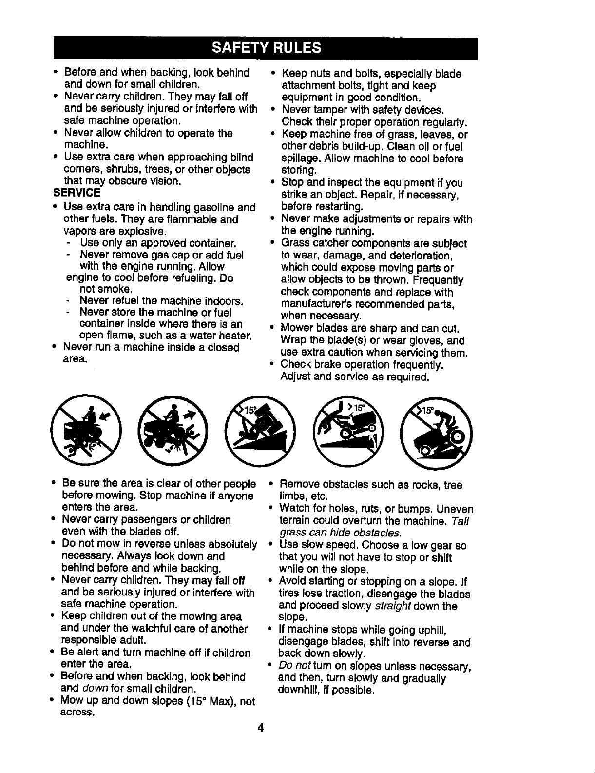
• Be sure the area isclear of other people
before mowing. Stop machine if anyone
enters the area.
• Never carry passengers or children
even with the blades off.
• Do not mow in reverse unless absolutely
necessary. Always look down and
behind before and while backing.
• Never carry children. They may fall off
and be seriously injured or interfere with
safe machine operation.
• Keep children out of the mowing area
and under the watchful care of another
responsible adult.
• Be alert and turn machine off ifchildren
enter the area.
• Before and when backing, look behind
and down for small children.
• Mow up and down slopes (15 =Max), not
across.
• Remove obstacles such as rocks, tree
limbs, etc.
• Watch for holes, ruts, or bumps. Uneven
terrain could overturn the machine. Ta//
grass can hide obstac/es.
• Use slow speed. Choose a low gear so
that you will not have to stop or shift
while on the slope.
• Avoid starting or stopping on a slope. If
tires lose traction, disengage the blades
and proceed slowly straight down the
slope.
• If machine stops while going uphill,
disengage blades, shift into reverse and
back down slowly.
• Do nottum on slopes unless necessary,
and then, turn slowly and gradually
downhill, ifpossible.
4
Page 5
ALook for this symbol to point out
important safety precautions. It means
CAUTIONIII BECOME AWAREIII YOUR
SAFETY IS INVOLVED.
_CAUTION: In order to prevent acciden-
tal starting when setting up, transporting,
adjusting or making repairs always
disconnect spark plug wire and place wire
where it cannot contact spark plug.
ACAUTION: Do not coast down a hill in
neutral, you may lose control of the tractor.
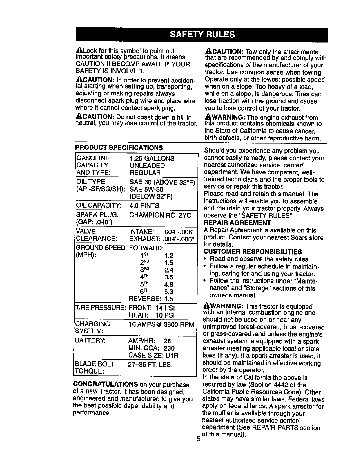
PRODUCT SPECIFICATIONS
GASOLINE 1.25 GALLONS
CAPACITY UNLEADED
AND TYPE: REGULAR
OIL TYPE SAE 30 (ABOVE 32°F)
API-SF/SG/SH): SAE 5W-30
(BELOW 32°F)
OIL CAPACITY: 4.0 PINTS
SPARK PLUG: CHAMPION RC12YC
GAP: .040")
VALVE INTAKE: .004"-.006"
CLEARANCE: EXHAUST: .004"-.006"
GROUND SPEED FORWARD:
(MPH): 1_ 1.2
2No 1.5
3RD 2.4
4TM 3.5
5TM 4,8
6TM 5.3
REVERSE: 1.5
TIRE PRESSURE: FRONT: 14 PSI
REAR: 10 PSI
CHARGING 16 AMPS@ 3600 RPM
SYSTEM:
BAT-I'ERY: AMP/HR: 28
MIN. CCA: 230
CASE SIZE: U1R
BLADE BOLT 27-35 FT. LBS.
TORQUE:
CONGRATULATIONS on your purchase
of a new Tractor. It has been designed,
engineered and manufactured to give you
the best possible dependability and
performance.
ACAUTION: Tow only the attachments
that are recommended by and comply with
specifications of the manufacturer of your
tractor. Use common sense when towing.
Operate only at the lowest possible speed
when on a slope. Too heavy of a load,
while on a slope, is dangerous. Tires can
lose traction with the ground and cause
you to lose control of your tractor.
AWARNING: The engine exhaust from
this product contains chemicals known to
the State of California to cause cancer,
birth defects, or other reproductive harm.
Should you experience any problem you
cannot easily remedy, please contact your
nearest authorized service center/
department. We have competent, well-
trained technicians and the proper toolsto
service or repair this tractor.
Please read and retain this manual. The
instructionswillenable you to assemble
and maintain your tractor properly. Always
observe the "SAFETY RULES".
REPAIR AGREEMENT
A Repair Agreement is available on this
product. Contact your nearest Sears store
for details.
CUSTOMER RESPONSIBILITIES
• Read and observe the safety rules.
• Follow a regular schedule in maintain-
ing, caring for and using your tractor.
• Follow the instructions under "Mainte-
nance" and "Storage" sections of this
owner's manual.
AWARNING: This tractor is equipped
with an internal combustion engine and
should not be used on or near any
unimproved forest-covered, brush-covered
or grass-covered land unless the engine's
exhaust system is equipped with a spark
arrester meeting applicable local or state
laws (if any). If a spark arrester is used, it
should be maintained in effective working
order by the operator.
In the state of California the above is
required by law (Section 4442 of the
California Public Resources Code). Other
states may have similar laws. Federal laws
apply on federal lands. A spark arrester for
the muffler is available through your
nearest authorized service center/
department (See REPAIR PARTS section
of this manual).
5
Page 6
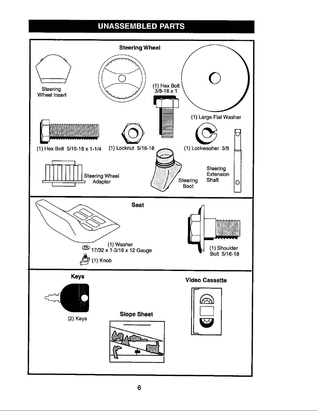
Steering
Wheel Insert
Steering Wheel
O
(1) Hex Bolt
3/8-16 x I
I_ (1) Large Flat Washer
@
(1) Hex Bolt 5/16-18 x 1-1/4
_ Steering Wheel
' I I , Adapter
17/32 x 1-3/16 x 12 Gauge
i_(1) Knob
Keys
(1) Locknut 5/16-18
Seat
(1) Washer
(1) Lockwasher 318
Steering
Extension
Steering Shaft
Boot
(1) Shoulder
Bolt 5/16-18
Video Casseffe
(2) Keys
Slope Sheet
6
Page 7
Your new tractor has been assembled at the factory with exception of those parts left
unassembled for shipping purposes. To ensure safe and proper operation of your
tractor all parts and hardware you assemble must be tightened securely. Use the
correct tools as necessary to insure proper tightness. Review the video cassette before
you begin.
TOOLS REQUIRED FOR
ASSEMBLY
A socket wrench set willmake assembly
easier. Standard wrench sizes you need
are listed below.
(1) 9/16" wrench (2) 1/2" wrench
(1) Utilityknife (1) Pliers
(1) Tire pressure gauge
When right or left hand is mentioned in
this manual, it means, from your point of
view, when you are in the operating
position (seated behind the steering
wheel).
TO REMOVE TRACTOR FROM
CARTON
UNPACK CARTON
• Remove all accessible loose parts and
parts boxes from shipping carton.
• Cut, from top to bottom, along lines on
all four corners of shipping carton, and
lay panels flat.
• Check for any additional loose parts or
boxes and remove.
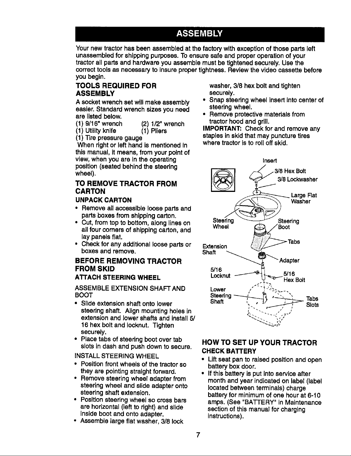
BEFORE REMOVING TRACTOR
washer, 3/8 hex bolt and tighten
securely.
• Snap steering wheel insert into center of
steering wheel.
• Remove protective materials from
tractor hood and grill.
IMPORTANT: Check for and remove any
staples inskid that may puncture tires
where tractor is to roll off skid.
Insert
/-_/3/8 HexBolt
y/3/8 Loekwasher
_ LargeRat
Wheel )__._Boot
Extension Tabs
Shaft
v.,_..
_--_ Adapter
FROM SKID
ATTACH STEERING WHEEL
L5/loc6nut-_'_:__ 5/16Bo,t
ASSEMBLE EXTENSION SHAFTAND
BOOT
• Slide extension shaft onto lower
steering shaft. Align mounting holes in
extension and lower shafts and install 5/
16 hex bolt and Iocknut. Tighten
securely.
• Place tabs of steering boot over tab
slots in dash and push down to secure.
INSTALL STEERING WHEEL
• Position front wheels of the tractor so
they are pointing straight forward.
• Remove steering wheel adapter from
steering wheel and slide adapter onto
steering shaft extension.
• Position steering wheel so cross bars
are horizontal (left to right) and slide
inside boot and onto adapter.
• Assemble large flat washer, 3/8 lock
Lower , . -'---
Steering _ ' "" ' Tabs
Shaft __ Slots
_ lit
HOW TO SET UP YOUR TRACTOR
CHECK BATTERY
Liftseat pan to raised position and open
battery box door.
If this battery is put into service after
month and year indicated on label (label
located between terminals) charge
battery for minimum of one hour at 6-10
amps. (See "BATTERY" in Maintenance
section of this manual for charging
instructions).
7
Page 8
BatteryBox
Door
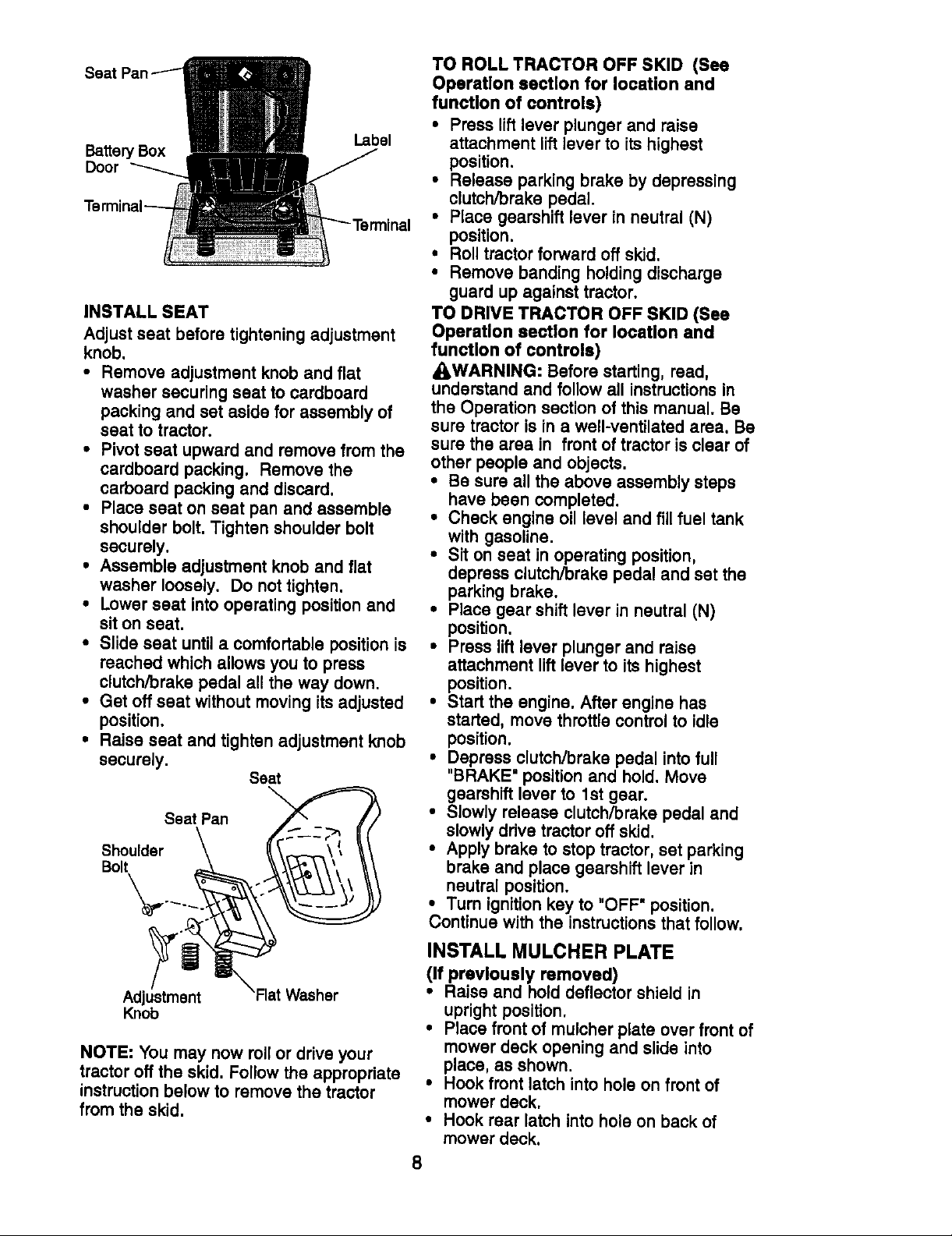
INSTALL SEAT
Adjust seat before tightening adjustment
knob.
• Remove adjustment knob and flat
washer securing seat to cardboard
packing and set aside for assembly of
seat to tractor.
• Pivot seat upward and remove from the
cardboard packing. Remove the
carboard packing and discard.
•Placa seat on seat pan and assemble
shoulder bolt. Tighten shoulder bolt
securely.
• Assemble adjustment knob and fiat
washer loosely. Do not tighten.
• Lower seat into operating positionand
sit on seat.
• Slide seat until a comfortable position is
roached which allows you to press
clutch/brake pedal all the way down.
• Get off seat without moving Its adjusted
position.
• Raise seat and tighten adjustment knob
securely.
Seat
SeatPan
Shoulder _ _ _._, _/
Bolt _ ,._
TO ROLL TRACTOR OFF SKID (See
Operetlon section for location and
function of controls)
• Press liftlever plunger and raise
attachment lift lever to its highest
position.
• Release parking brake by depressing
clutch/brake pedal.
• Place gearshift lever in neutral (N)
position.
• Roll tractor forward off skid.
• Remove banding holding discharge
guard up against tractor.
TO DRIVE TRACTOR OFF SKID (See
Operation section for location and
function of controls)
_WARNING: Before starting, read,
understand and follow all instructionsin
the Operation section of this manual. Be
sure tractor is in a well-ventilated area. Be
sure the area in front of tractor is clear of
other people and objects.
• Be sure all the above assembly steps
have been completed.
• Check engine oil level and fillfuel tank
with gasoline.
• Sit on seat in operating position,
depress clutch/brake pedal and set the
parking brake.
• Place gear shift lever in neutral (N)
position.
• Press lift lever plunger and raise
attachment lift lever to Its highest
position.
• Start the engine. After engine has
started, move thro_tlecontrol to idle
position.
• Depress clutch/brake pedal into full
"BRAKE" position and hold. Move
gearshift lever to 1st gear.
• Slowly release clutch/brake pedal and
slowly drive tractor off skid.
• Apply brake to stop tractor, set parking
brake and place gearshift lever in
neutral position.
• Turn ignitionkey to "OFF" position.
Continue with the instructions that follow.
Adjus_tm_nt_Flat Washer
Knob
NOTE: You may now rollor drive your
tractor off the skid. Follow the appropriate
instruction below to remove the tractor
from the skid.
INSTALL MULCHER PLATE
(If previously removed)
• Raise and hold deflector shield in
upright position.
• Piece front of mulcher plate over front of
mower deck opening and slide Into
place, as shown.
• Hook front latch into hole on front of
mower deck.
• Hook rear latch into hole on back of
mower deck.
8
Page 9
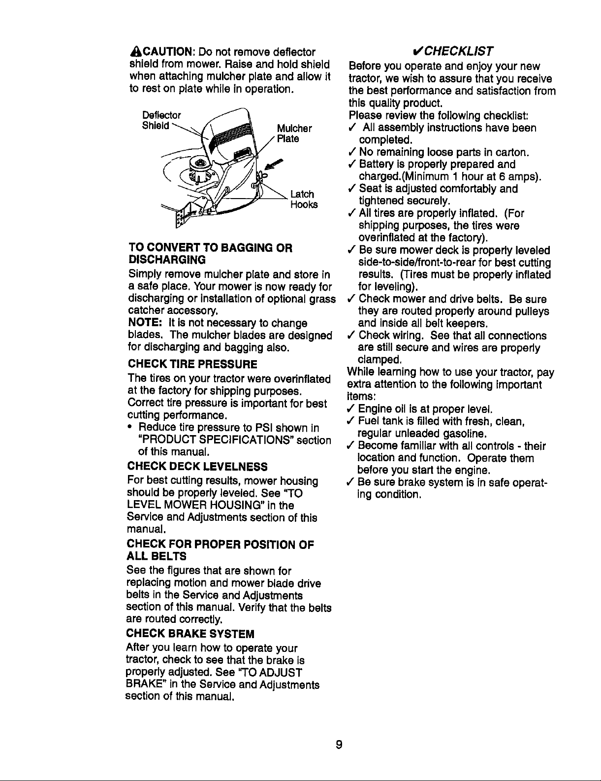
_,CAUTION: Do not remove deflector
shield from mower. Raise and hold shield
when attaching mulcher plate and allow it
to rest on plate while in operation.
Deflector
Shield_('\ _ Mulcher
( t
Hoo_
TO CONVERT TO BAGGING OR
DISCHARGING
Simply remove mulcher plate and store in
a safe place. Your mower is now ready for
discharging or installation of optional grass
catcher accessory.
NOTE: It is not necessary to change
blades. The mulcher blades are designed
for discharging and bagging also.
CHECK TIRE PRESSURE
The tires on your tractor were overinflated
at the factory for shipping purposes.
Correct tire pressure is important for best
cutting performance.
• Reduce tire pressure to PSI shown in
"PRODUCT SPECIFICATIONS" section
of this manual.
CHECK DECK LEVELNESS
For best cutting results, mower housing
should be properly leveled. See "TO
LEVEL MOWER HOUSING" in the
Service and Adjustments section of this
manual.
CHECK FOR PROPER POSITION OF
ALL BELTS
See the figures that are shown for
replacing motion and mower blade drive
belts in the Service and Adjustments
section of this manual, Verify that the belts
are routed correctly,
CHECK BRAKE SYSTEM
After you learn how to operate your
tractor, check to see that the brake is
properly adjusted. See "TO ADJUST
BRAKE" in the Service and Adjustments
section of this manual.
v' CHECKLIST
Before you operate and enjoy your new
tractor, we wish to assure that you receive
the best performance and satisfaction from
this quality product.
Please review the following checklist:
/ All assembly instructionshave been
completed.
/ No remaining loose parts in carton.
,/Battery is properly prepared and
charged.(Minimum 1 hour at 6 amps).
,/Seat is adjusted comfortably and
tightened securely.
,/All tires are properly inflated. (For
shipping purposes, the tires were
overinflated at the factory).
,/Be sure mower deck is properly leveled
side-to-side/front-to-rear for best cutting
results. (Tires must be properly inflated
for leveling).
,/Check mower and drive belts. Be sure
they are routed properly around pulleys
and inside all belt keepers.
,/Check wiring. See that all connections
are still secure and wires are properly
clamped.
While learning how to use your tractor, pay
extra attention to the following important
items:
4 Engine oil isat proper level.
/ Fuel tank is filled with fresh, clean,
regular unleaded gasoline.
/ Become familiar with all controls - their
location and function. Operate them
before you start the engine.
4"Be sure brake system is in safe operat-
ing condition.
9
Page 10
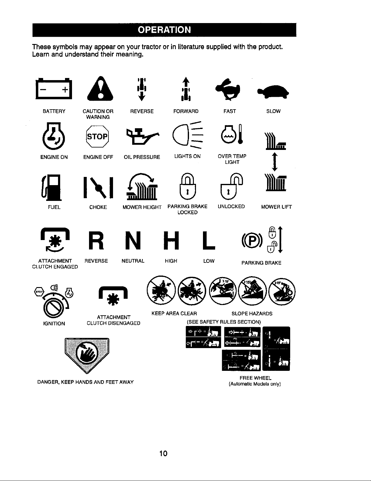
These symbols may appear on your tractor or in literature supplied withthe product,
Learn and understand their meaning,
BATTERY CAUTION OR
WARNING
ENGINE ON ENGINE OFF OIL PRESSURE
REVERSE FORWARD FAST SLOW
LIGHTSONO%_MP
FUEL CHOKE MOWER HEIGHT PARKING BRAKE UNLOCKED MOWER LIFT
LOCKED
R N H L
A'N'ACHMENT REVERSE NEUTRAL HIGH LOW PARKING BRAKE
CLUTCH ENGAGED
A37"ACHMENT KEEP AREA CLEAR SLOPE HAZARDS
IGNITION CLUTCH DISENGAGED (SEE SAFETY RULES SECTION)
DANGER, KEEP HANDS AND FEET AWAY
FREE WHEEL
(Automatic Models only)
10
Page 11
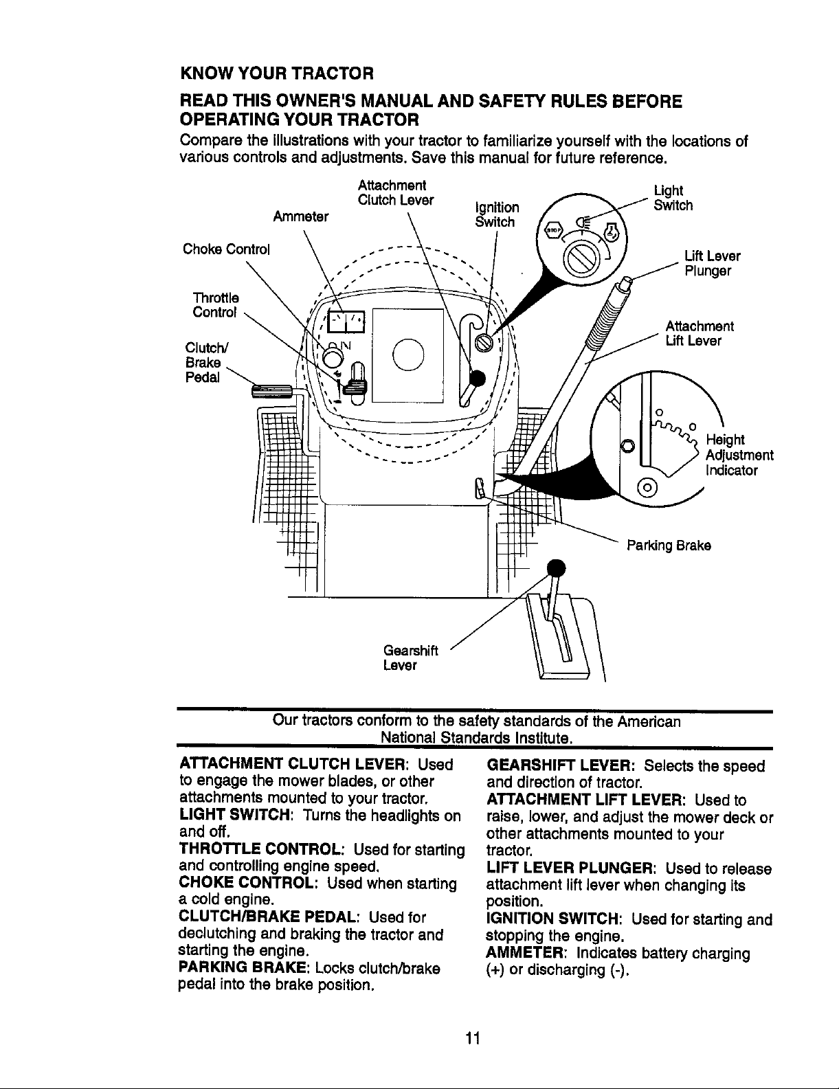
KNOW YOUR TRACTOR
READ THIS OWNER'S MANUAL AND SAFETY RULES BEFORE
OPERATING YOUR TRACTOR
Comparethe illustrationswithyourtractortofamiliarizeyourselfwiththe locationsof
variouscontrolsandadjustments.Save thismanualforfuturereference,
Attachment Light
Ammeter Switch
Clutch Lever Ignition Switch
Choke Control
Throttle
Control
Clutch/
Brake
Pedal
Lift Lever
Plunger
Attachment
Lift Lever
o
O
Height
Adjustment
Indicator
Parking Brake
Gearshift
Lever
Our tractors conform to the safety standards of the American
National Standards Institute.
ATTACHMENT CLUTCH LEVER: Used
to engage the mower blades, or other
attachments mounted to your tractor.
LIGHT SWITCH: Turns the headlights on
and off.
THROTTLE CONTROL: Used for starting
and controlling engine speed,
CHOKE CONTROL: Used when starting
a cold engine.
CLUTCH/BRAKE PEDAL: Used for
declutching and braking the tractor and
starting the engine.
PARKING BRAKE: Locks clutch/brake
pedal into the brake position.
GEARSHIFT LEVER: Selects the speed
and direction of tractor.
ATTACHMENT LIFT LEVER: Used to
raise, lower, and adjust the mower deck or
other attachments mounted to your
tractor.
LIFT LEVER PLUNGER: Used to release
attachment liftlever when changing its
position.
IGNITION SWITCH: Used for starting and
stopping the engine.
AMMETER: Indicates battery charging
(+) or discharging (-).
11
Page 12
The operation of any tractor can result in foreign objects thrown into the
eyes, which can result in severe eye damage. Always wear safety
glasses or eye shields while operating your tractor or performing any
adjustments or repairs. We recommend a wide vision safety mask over
spectacles, or standard safety glasses.
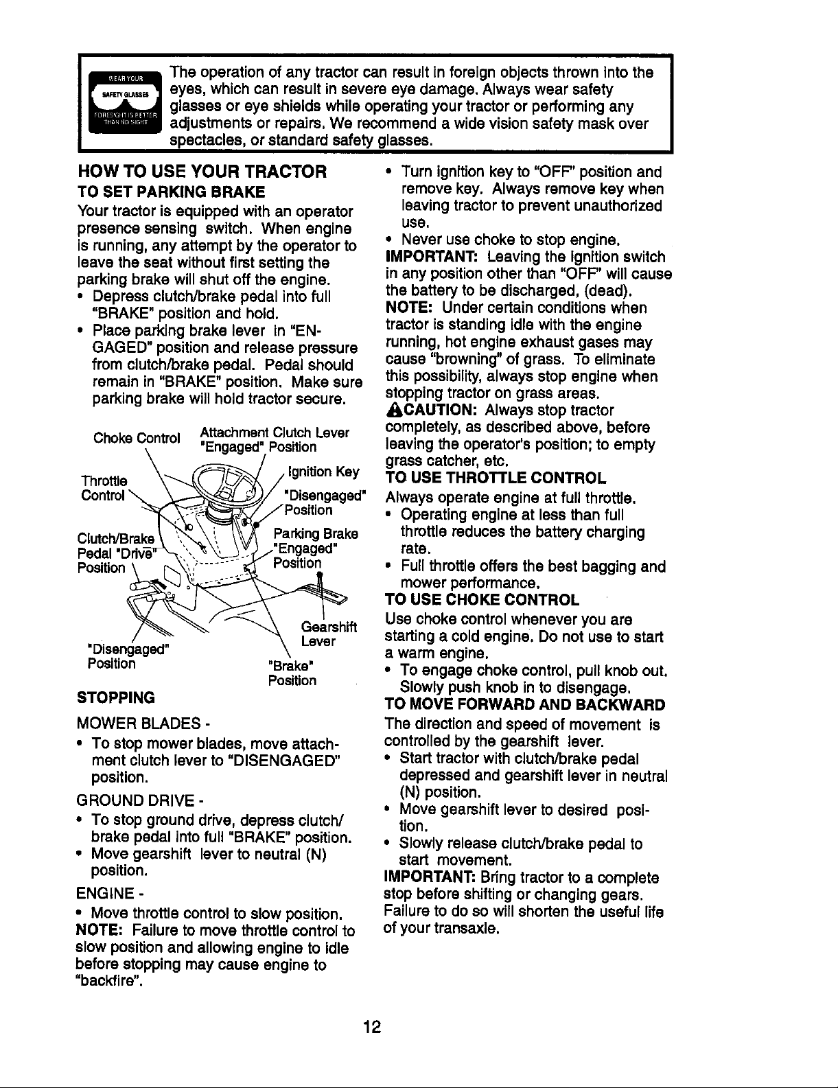
HOW TO USE YOUR TRACTOR
TO SET PARKING BRAKE
Your tractor is equipped with an operator
presence sensing switch. When engine
is running,any attempt by the operator to
leave the seat without first setting the
parking brake willshut off the engine.
• Depress clutch/brake pedal into full
"BRAKE" position and hold.
• Place parking brake lever in "EN-
GAGED" position and release pressure
from clutch/brake pedal. Pedal should
remain in "BRAKE" position. Make sure
parking brake will hold tractor secure.
Choke Control
Throttle _
Control
Clutch/Brak=
Pedal "Drive'_
'Disengaged"
Position
STOPPING
MOWER BLADES -
• To stop mower blades, move attach-
ment clutch lever to "DISENGAGED"
position.
GROUND DRIVE -
• To stop ground drive, depress clutch/
brake pedal intofull "BRAKE" position.
• Move gearshift lever to neutral (N)
position.
ENGINE -
• Move throttle control to slow position.
NOTE: Failure to move throttle control to
slow position and allowing engine to idle
before stopping may cause engine to
"backfire".
AttachmentClutchLever
"Engaged"Position
_-_ //Ignition Key
I-_ y. "Disengaged"
_ yPosition
_,,,-_,, I ParkingB_ake
.". "_',__ / Engaged
Position
"Brake'
Position
• Turn ignition key to "OFF" position and
remove key. Always remove key when
leaving tractor to prevent unauthorized
use.
• Never use choke tostopengine.
IMPORTANT: Leavingtheignitionswitch
inany positionotherthan"OFF" willcause
thebatterytobe discharged,(dead).
NOTE: Under certainconditionswhen
tractorisstandingidlewiththeengine
running,hotengineexhaustgases may
cause "browning"ofgrass.To eliminate
thispossibility,always stopenginewhen
stopping tractor on grass areas.
ACAUTION: Always stop tractor
completely, as described above, before
leaving the operator's position;to empty
grass catcher, etc.
TO USE THROTTLE CONTROL
Always operate engine at full throttle.
• Operating engine at less than full
throttle reduces the battery charging
rate.
• Full throttle offers the best bagging and
mower performance.
TO USE CHOKE CONTROL
Use choke control whenever you are
starting a cold engine. Do not use to start
a warm engine.
• To engage choke control, pull knob out.
Slowly push knob in to disengage.
TO MOVE FORWARD AND BACKWARD
The direction and speed of movement is
controlled by the gearshift lever.
• Start tractor with clutch/brake pedal
depressed and gearshift lever in neutral
(N) position.
• Move gearshift lever to desired posi-
tion.
• Slowly release clutch/brake pedal to
start movement.
IMPORTANT: Bring tractor to a complete
stop before shiftingor changing gears.
Failure to do so willshorten the useful life
of your transaxle.
12
Page 13
TO ADJUST MOWER CUTTING
HEIGHT
The position of the attachment lift lever
determines the cutting height.
• Grasp liftlever.
• Press plunger with thumb and move
lever to desired position.
The cutting height range is approxi-
mately 1-1/2 to 4". The heights are
measured from the ground to the blade tip
with the engine not running. These
heights are approximate and may vary
depending upon soil conditions, height of
grass and types of grass being mowed.
• The average lawn should be cut to
approximately 2-1/2 inches during the
cool season and to over 3 inches during
hot months. For healthier and better
looking lawns, mow often and after
moderate growth.
• For best cutting performance, grass over
6 inches in height should be mowed
twice. Make the first cut relatively high;
the second to desired height.
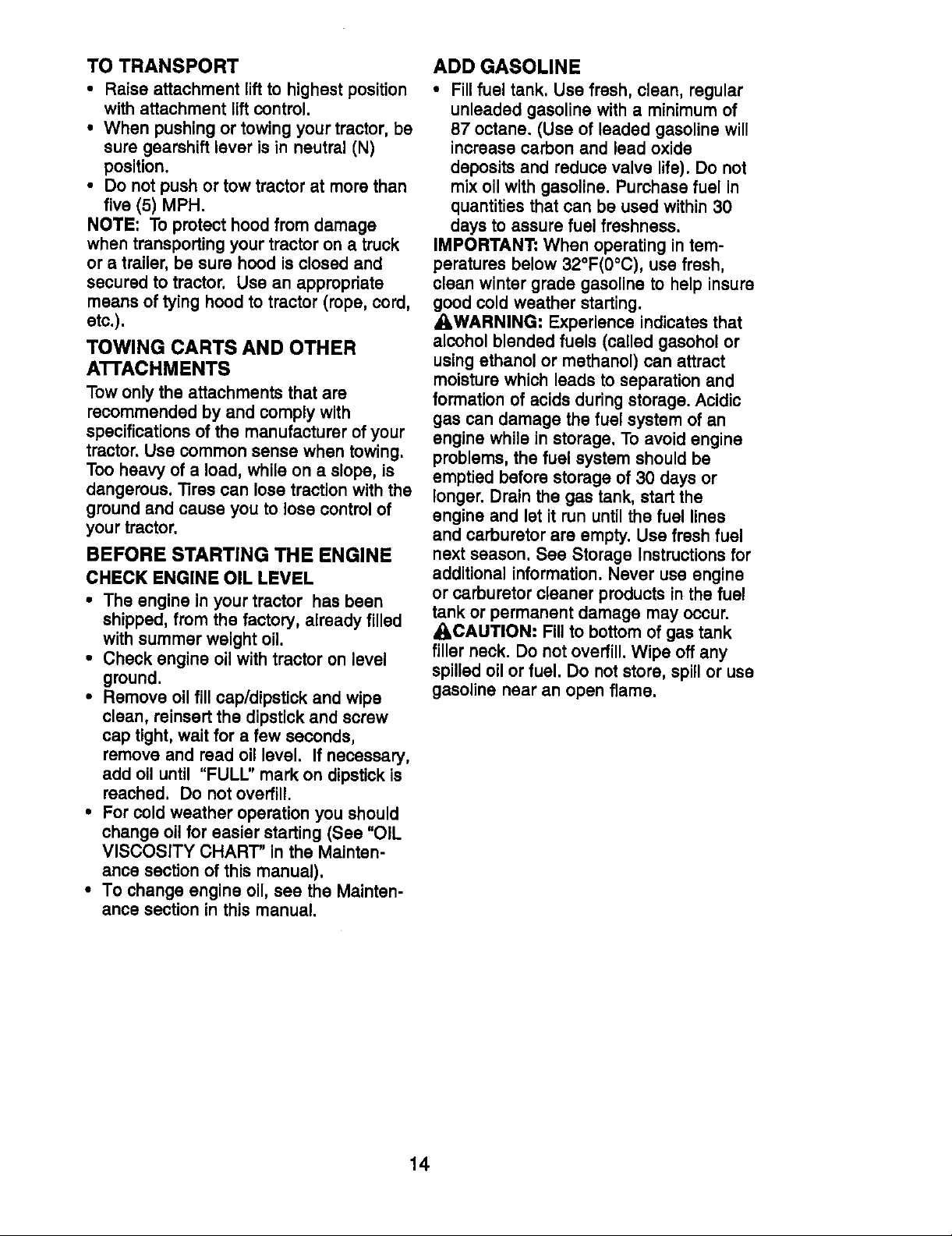
TO ADJUST GAUGE WHEELS
Gauge wheels are properly adjusted
when they are slightly off the ground when
mower is at the desired cutting height in
operating position. Gauge wheels then
keep the deck in proper position to help
prevent scalping in most terrain conditions.
• Adjust gauge wheels with tractor on a
flat level surface.
• Adjust mower to desired cutting height
(See 'TO ADJUST MOWER CUTTING
HEIGHT" in the Operation section of this
manual).
• With mower in desired height of cut
position, gauge wheels should be
assembled so they are slightly off the
ground. Install gauge wheel in appropri-
ate hole with shoulder bolt, 3/8 washer,
and 3/8-16 Iocknut and tighten securely.
• Repeat for opposite side installing
gauge wheel in same adjustment hole.
GaugeWheel .2_-_-_,_
Mounting\ _F f _
Bracket "'_ \ _i_ _
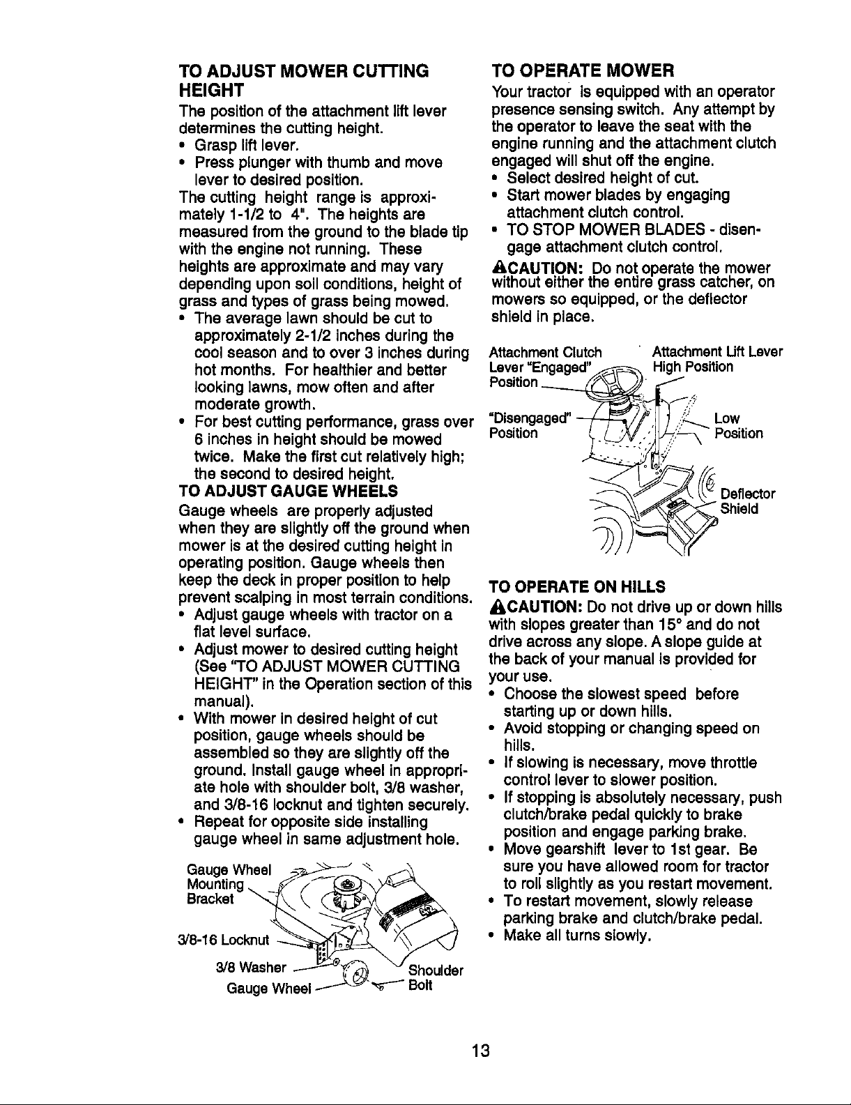
TO OPERATE MOWER
Your tractor is equipped with an operator
presence sensing switch. Any attempt by
the operator to leave the seat with the
engine running and the attachment clutch
engaged will shut off the engine.
• Select desired height of cut.
• Start mower blades by engaging
attachment clutch control.
• TO STOP MOWER BLADES - disen-
gage attachment clutch control.
ACAUTION: Do not operate the mower
without either the entire grass catcher, on
mowers so equipped, or the deflector
shield in place.
Attachment Clutch
Lever "Engaged"
Position Position
• Attachment Uft Lever
High Position
Low
TO OPERATE ON HILLS
• kCAUTION: Do not drive up or down hills
with slopes greater than 15° and do not
drive across any slope, A slope guide at
the back of your manual is provided for
your use.
• Choose the slowest speed before
starting up or down hills.
• Avoid stopping or changing speed on
hills.
• If slowing is necessary, move throttle
control lever to slower position.
• If stopping is absolutely necessary, push
clutch/brake pedal quickly to brake
position and engage parking brake.
• Move gearshift lever to lst gear. Be
sure you have allowed room for tractor
to rollslightly as you restart movement.
• To restart movement, slowly release
parking brake and clutch/brake pedal.
• Make all turns slowly.
3/8 Washer __...E-_ ._ "J Shoulder
GaugeWheel_ _ Bolt
13
Page 14
TO TRANSPORT
• Raise attachment lift to highest position
with attachment lift control.
• When pushing or towing your tractor, be
sure gearshift lever is in neutral (N)
position.
• Do not push or tow tractor at more than
five (5) MPH.
NOTE: To protect hood from damage
when transporting your tractor on a truck
or a trailer, be sure hood is closed and
secured to tractor. Use an appropriate
means of tying hood to tractor (rope, cord,
etc.).
TOWING CARTS AND OTHER
A'I-I'ACHMENTS
Tow only the attachments that are
recommended by and comply with
specifications of the manufacturer of your
tractor. Use common sense when towing.
Too heavy of a load, while on a slope, is
dangerous. "liros can lose traction withthe
ground and cause you to lose control of
your tractor.
BEFORE STARTING THE ENGINE
CHECK ENGINE OIL LEVEL
• The engine in your tractor has been
shipped, from the factory, already filled
with summer weight oil.
• Check engine oil with tractor on level
ground.
• Remove oil fill cap/dipstick and wipe
clean, reinsert the dipstick and screw
cap tight, wait for a few seconds,
remove and read oil level. If necessary,
add oil until "FULU' mark on dipstick is
roached. Do not overfill.
• For cold weather operation you should
change oil for easier starting (See "OIL
VISCOSITY CHART" in the Mainten-
ance section of this manual).
• To change engine oil, see the Mainten-
ance section in this manual.
ADD GASOLINE
• Fill fuel tank. Use fresh, clean, regular
unleaded gasoline with a minimum of
87 octane. (Use of leaded gasoline will
increase carbon and lead oxide
deposits and reduce valve life). Do not
mix oil with gasoline. Purchase fuel in
quantities that can be used within 30
days to assure fuel freshness.
IMPORTANT: When operating in tem-
peraturos below 32°F(0°C), use fresh,
clean winter grade gasoline to help insure
good cold weather starting.
_WARNING: Experience indicates that
alcohol blended fuels (called gasohol or
using ethanol or methanol) can attract
moisture which leads to separation and
formation of acids duringstorage. Acidic
gas can damage the fuel system of an
engine while in storage. To avoid engine
problems, the fuel system should be
emptied before storage of 30 days or
longer. Drain the gas tank, start the
engine and let it run until the fuel lines
and carburetor are empty. Use fresh fuel
next season. See Storage Instructionsfor
additional information. Never use engine
or carburetor cleaner products in the fuel
tank or permanent damage may occur.
ACAUTION: Fill to bottom of gas tank
filler neck. Do not overfill. Wipe off any
spilled oil or fuel. Do not store, spill or use
gasoline near an open flame.
14
Page 15
TO START ENGINE
When starting the engine for the firsttime
or if the engine has run out of fuel, it will
take extra cranking time to move fuel from
the tank to the engine.
• Sit on seat in operating position,
depress clutch/brake pedal and set
parking brake.
• Place gear shift lever in neutral (N)
position.
• Move attachment clutch to "DISEN-
GAGED" position.
• Move throttle control to fast position
• Pull choke control out for a cold engine
start attempt. For a warm engine start
attempt the choke control may not be
needed.
NOTE: Before starting, read the warm and
cold starting procedures below.
• Insert key into ignitionand turn key
clockwise to "START" position and
release key as soon as engine starts.
Do not run starter continuouslyfor more
than fifteen seconds per minute. If the
engine does not start after several
attempts, push choke control in, wait a
few minutes and try again. If engine still
does not start, pull the choke control out
and retry.
WARM WEATHER STARTING (50° F
AND ABOVE)
• When engine starts, slowly push choke
control in untilthe engine begins to run
smoothly. If the engine starts to run
roughly, pull the choke controlout
slightly for a few seconds and then
continue to push the control in slowly.
• The attachments and ground drive can
now be used. If the enginedoes not
accept the load, restart the engine and
allow it to warm up for one minute using
the choke as described above.
COLD WEATHER STARTING (50° F AND
BELOW)
• When engine starts, slowly push choke
control in until the engine begins to run
smoothly. Continue to push the choke
control in small steps allowing the
engine to accept small changes in
speed and load, until the choke control
is fully in. If the engine starts to run
roughly, pull the choke control out
slightly for a few seconds and then
continue to push the control in slowly.
This may require an engine warm-up
period from several seconds to several
minutes, depending on the temperature.
• The attachments can be used during the
engine warm-up period and may require
the choke control be pulled out slightly.
NOTE" A high altitude (above 3000 feet) or
in cold temperatures (below 32 F) the
carburetor fuel mixture may need to be
adjusted for best engine performance. See
"3"0 ADJUST CARBURETOR" in the
Service and Adjustments section of this
manual.
15
Page 16
MOWING TIPS
• Mower should be properly leveled for
best mowing performance. See 'q'O
LEVEL MOWER HOUSING" in the
Service and Adjustments section of this
manual.
• The left hand side of mower should be
used for trimming.
• Drive so that clippings are discharged
onto the area that has been cut. Have
the cut area to the right of the machine.
This will result in a more even distribu-
tion of clippingsand more uniform
cutting.
• When mowing large areas, start by
turning to the rightso that clippings will
discharge away from shrubs, fences,
driveways, etc. After one or two rounds,
mow in the opposite direction making left
hand turns untilfinished
• If grass is extremely tall, itshould be
mowed twice to reduce load and
possible fire hazard from dried clippings.
Make first cut relatively high; the second
to the desired height.
• Do not mow grass when it is wet. Wet
grass will plug mower and leave
undesirable clumps. Allow grass to dry
before mowing.
• Always operate engine at full throttle
when mowing to assure better mowing
performance and proper discharge of
material. Regulate ground speed by
selecting a low enough gear to give the
mower the best cutting performance as
well as the quality of cut desired.
• When operating attachments, select a
ground speed that will suit the terrain
and give best performance of the
attachment being used.
MULCHING MOWING TIPS
IMPORTANT: For best performance, keep
mower housing free of built-up grass and
trash, Clean after each use.
• The special mulching blade will recut
the grass clippings many times and
reduce them in size so that as they fall
onto the lawn they will disperse into the
grass and not be noticed. Also, the
mulched grass will biodegrade quickly to
provide nutrients for the lawn. Always
mulch with your highest engine (blade)
speed as this will provide the best
recutting action of the blades.
• Avoid cutting your lawn when it is wet.
Wet grass tends to form clumps and
interferes with the mulching action. The
best time to mow your lawn is the early
afternoon. At this time the grass has
dried and the newly cut area will not be
exposed to the direct sun.
• For best results, adjust the mower
cutting height so that the mower cuts off
only the top one-third of the grass
blades. For extremely heavy mulching,
reduce your width of cut on each pass
and mow slowly.
• Certain types of grass and grass
conditions may require that an area be
mulched a second time to completely
hide the clippings. When doing a
second cut, mow across or perpendicu-
lar to the first cut path.
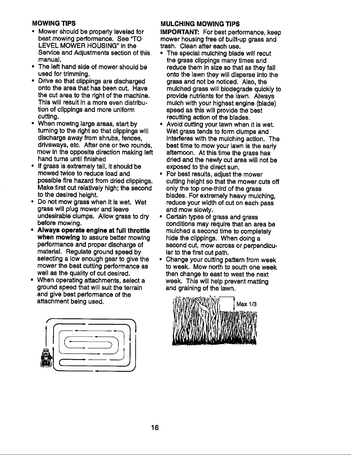
• Change your cutting pattern from week
to week. Mow northto south one week
then change to east to west the next
week. This will help prevent matting
and graining of the lawn.
Max 1/3
16
Page 17
FiLLINOATE
Check Brake Operation _
Check 13re Pressure
Check Operalor Presence and
T Intedock Systems ll_
R Check for Loose Fi_steners V / I_z I_
A Sharpe,VRepfaceUowe,B,ades _,
T Lubrication Chart
0 Check Battery Level
R Clean Battery and Terminals I_
Check Transsxle Cooling
Adjust Blade Belt(s) Tension Ks
Adjust Motion Ddve Belt(s) Tension V's
Check Engine Oil Level I1_ I##
Change Engine Oil V_1.2,_
E Clean Air Filter 11_2
N Clean Air Screen V/2
G Inspect Muffler/Spark Arrester
Replace Oil Filter (If equipped) _,=
N Clean Engine Coo_ing Fins If z
Replace Spark Plug _ If
Replace Air Filter Paper Cartridge V'=
Replace Fuel Filter I1_
1 - Cha,_ge mo_e ellen when operating under a heaW kind or In h,_h ambient lemperahJres 5 - t/equipped with adjustable system.
2 - Sefv_e more offBnwhen operating indirty or dust'/cor,ditlo_s, 5 - Not _qulred I/Qquipped with malntBnanc_-free batter 4.
3 - Ifequipped with c_lfilter, ¢henge oil even/50 hours, 7 - Tighten front aXlepivol boll to 35 rt.-Ibs, maxln_m,
4 - Replace b_adesmore often when mowing in man_ysoil, Donet overti_hten.
v'
GENERAL RECOMMENDATIONS
The warranty on this tractor does not
cover items that have been subjected to
operator abuse or negligence. To receive
full value from the warranty, operator must
maintain tractor as instructed in this
manual.
Some adjustments will need to be made
periodically to properly maintain your
tractor.
All adjustments in the Service and
Adjustments section of this manual should
be checked at least once each season.
• Once a year you should replace the
spark plug, clean or replace air filter,
and check blades and belts for wear. A
new spark plug and clean air filter
assure proper air-fuel mixture and help
your engine run better and last longer.
BEFORE EACH USE
• Check engine oil level.
• Check brake operation,
• Check tire pressure.
• Check operator presence and interlock
systems for proper operation.
• Check for loose fasteners.
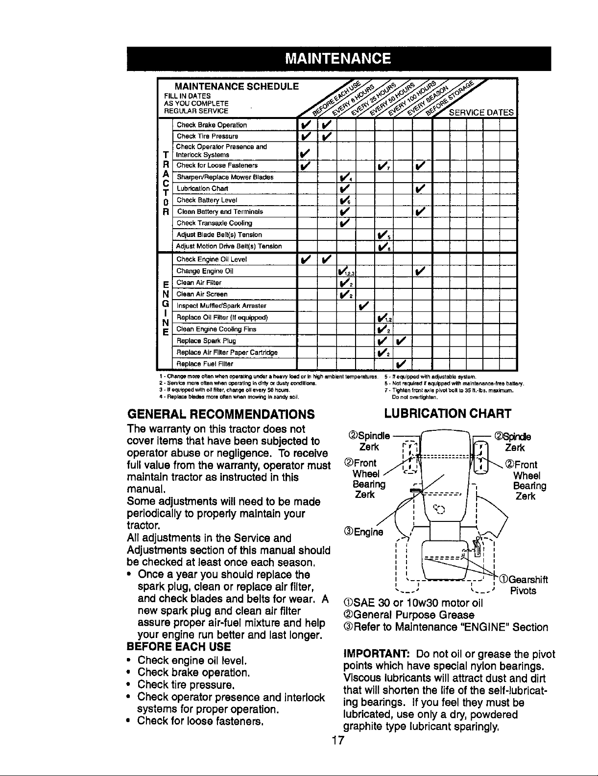
LUBRICATION CHART
- _Spinde
Zerk Zerk
@Front (_Front
Wheel Wheel
Bearing -, Beadng
Zerk Zerk
@Engine
I
I
I
- - - ' - - - _ Pivots
OSAE 30 or 10w30 motor oil
@General Purpose Grease
@Refer to Maintenance "ENGINE" Section
IMPORTANT: Do not oil or grease the pivot
points which have special nylon bearings.
Viscous lubricants will attract dust and dirt
that willshorten the life of the self-lubricat-
ing bearings. Ifyou feel they must be
lubricated, use only a dry, powdered
graphite type lubricant sparingly.
17
f I
Page 18
TRACTOR
Always observe safety rules when
performing any maintenance.
BRAKE OPERATION
If tractor requires more than six (6) feet
stopping distance at high speed in highest
gear, then brake must be adjusted. (See
"TO ADJUST BRAKE" in the Service and
Adjustments section of this manual).
TIRES
• Maintain proper air pressure in all tires
(See "PRODUCT SPECIFICATIONS"
section of this manual).
• Keep tires free of gasoline, oil, or insect
control chemicals which can harm
rubber.
• Avoid stumps, stones, deep ruts, sharp
objects and other hazards that may
cause tire damage.
NOTE: To seal tire punctures and prevent
flat tires due to slow leaks, tire sealant
may be purchased from your local parts
dealer. Tire sealant also prevents tire dry
rotand corrosion.
OPERATOR PRESENCE SYSTEM
Be sure that operator presence and
interlock systems are working propedy. If
your tractor does not function as described
below, repair the problem immediately.
• The engine should not start unless the
clutch/brake pedal is fully depressed
and attachment clutch control is in the
disengaged position.
• When the engine is running, any
attempt by the operator to leave the seat
without first setting the parking brake
should shut off the engine.
• When the engine is running and the
attachment clutch is engaged, any
attempt by the operator to leave the seat
should shut off the engine.
• The attachment clutch should never
operate unless the operator is in the
seat.
BLADE CARE
For best results mower blades must be
kept sharp. Replace bent or damaged
blades.
BLADE REMOVAL
• Raise mower to highest position to allow
access to blades.
• Remove hex bolt, look washer and flat
washer securing blade.
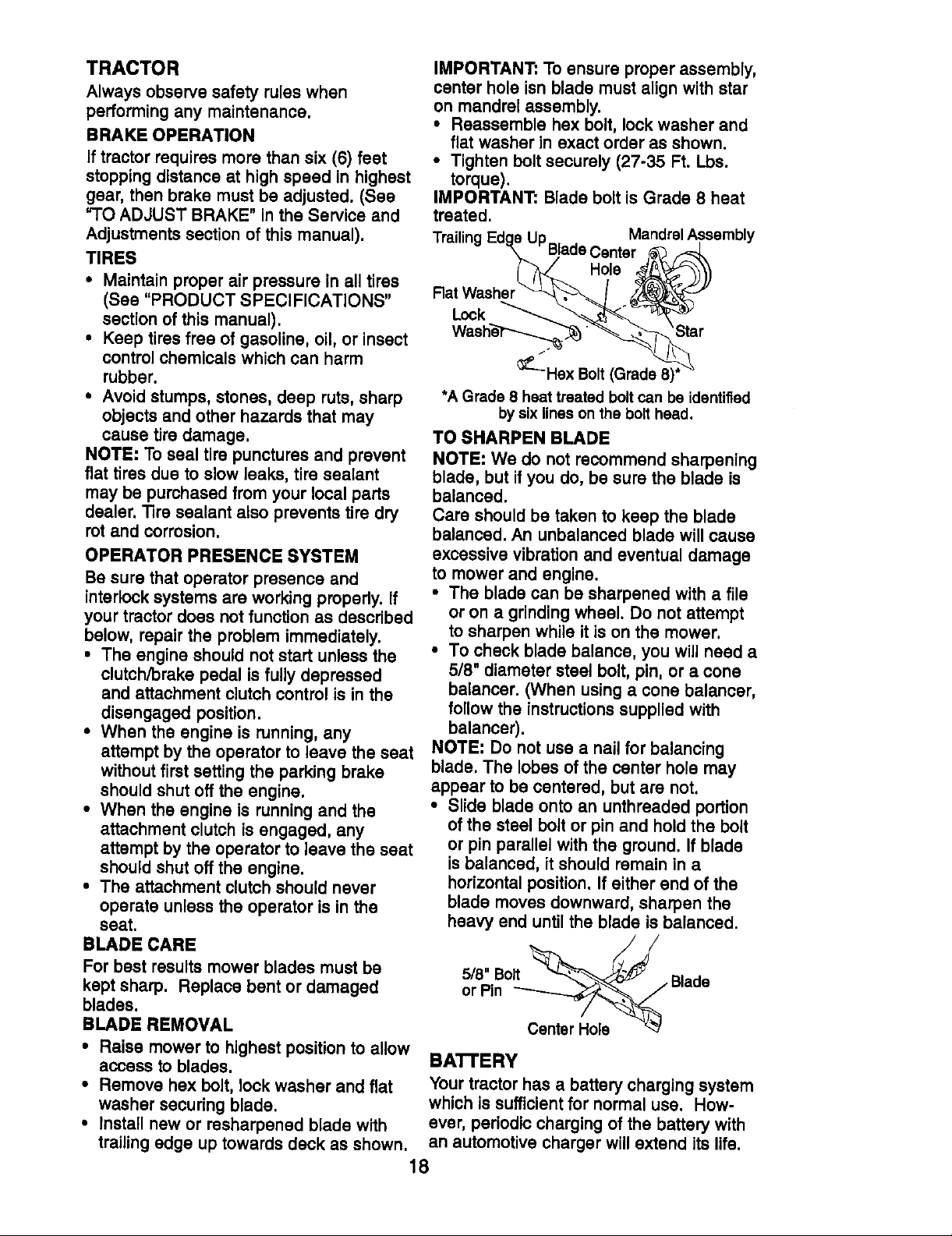
• install new or resharpened blade with
trailing edge up towards deck as shown.
IMPORTANT: To ensure proper assembly,
center hole isn blade must align with star
on mandrel assembly.
• Reassemble hex bolt, lock washer and
flat washer in exact order as shown.
• Tighten boltsecurely (27-35 Ft. Lbs.
torque).
IMPORTANT: Blade bolt is Grade 8 heat
treated.
Trailinc Up MandrelAssembly
BladeCenter
Hole
Rat Washer
Lock
Washe_---...._. _Star
_:-Hex Bolt(Grade8)'
*AGrade8 heattreatedboltcan be identified
bysixlinesonthe bolt head.
TO SHARPEN BLADE
NOTE: We do not recommend sharpening
blade, but if you do, be sure the blade is
balanced.
Care should be taken to keep the blade
balanced. An unbalanced blade will cause
excessive vibration and eventual damage
to mower and engine.
• The blade can be sharpened with a file
or on a grindingwheel. Do not attempt
to sharpen while it is on the mower.
• To check blade balance, you will need a
5/8" diameter steel bolt, pin, or a cone
balancer. (When using a cone balancer,
follow the instructionssupplied with
balancer).
NOTE: Do not use a nail for balancing
blade. The lobes of the center hole may
appear to be centered, but are not.
• Slide blade onto an unthraaded portion
of the steel bolt or pin and hold the bolt
or pin parallel with the ground. If blade
is balanced, it should remain in a
horizontal position. If either end of the
blade moves downward, sharpen the
heavy end until the blade is balanced.
5/8" Bolt _
or Pin ------------.__Y._,_'_.7" Blade
BATTERY
Your tractor has a battery charging system
which is sufficient for normal use. How-
ever, periodic charging of the battery with
an automotive charger will extend its life.
18
Page 19
• Keep battery and terminals clean.
• Keep battery bolts tight.
• Keep small vent holes open.
• Recharge at 6-10 amperes for 1 hour.
NOTE: The original equipment battery on
your tractor is maintenance free. Do not
attempt to open or remove caps or covers.
Adding or checking level of electrolyte is
not necessary.
TO CLEAN BATTERY AND TERMINALS
Corrosion and dirt on the battery and
terminals can cause the battery to "leak"
power.
• Open battery box door.
• Disconnect BLACK battery cable first
then RED battery cable and remove
battery from tractor.
• Rinse the battery with plain water and
dry.
• Clean terminals and battery cable ends
with wire brush untilbright.
• Coat terminals with grease or petroleum
jelly.
• Reinstall battery (See "REPLACING
BATTERY" in the SERVICE AND
ADJUSTMENTS section of this manual).
V-BELTS
Check V-belts for deterioration and wear
after 100 hours of operation and replace if
necessary. The belts are not adjustable.
Replace belts if they begin to slip from
wear.
TRANSAXLE COOLING
Keep transaxle free from build-up of dirt
and chaff which can restrict cooling.
ENGINE
LUBRICATION
Only use high quality detergent oil rated
with API service classification SF, SG, or
SH. Select the oil's SAE viscosity grade
according to your expected operating
temperature.
SAE VISCOSITY GRADES
NOTE: Although multi-viscosity oils
(5W30, 10W30 etc.) improve starting in
cold weather, these multi-viscosity oils will
result in increased oil consumption when
used above 32°F. Check your engine oil
level more frequently to avoid possible
engine damage from runninglow on oil.
Change the oil after every 50 hours of
operation or at least once a year if the
tractor is not used for 50 hours in one
year.
Check the crankcase oil level before
starting the engine and after each eight
(8) hours of operation. "nghtenoil fill cap/
dipstick securely each time you check the
oil level.
TO CHANGE ENGINE OIL
Determine temperature range expected
before oil change. All oil must meet API
service classification SF, SG or SH.
• Be sure tractor is on level surface.
• Oil will drain more freely when warm.
• Catch oil in a suitable container.
• Remove oil fill cap/dipstick. Be careful
not to allow dirt to enter the engine
when changing oil.
• Remove drain plug.
• After oil has drained completely, replace
oil drain plug and tighten securely.
• Refill engine with oil through oil fill
dipstick tube. Pour slowly. Do not
overfill. For approximate capacity see
"PRODUCT SPECIFICATIONS" section
of this manual.
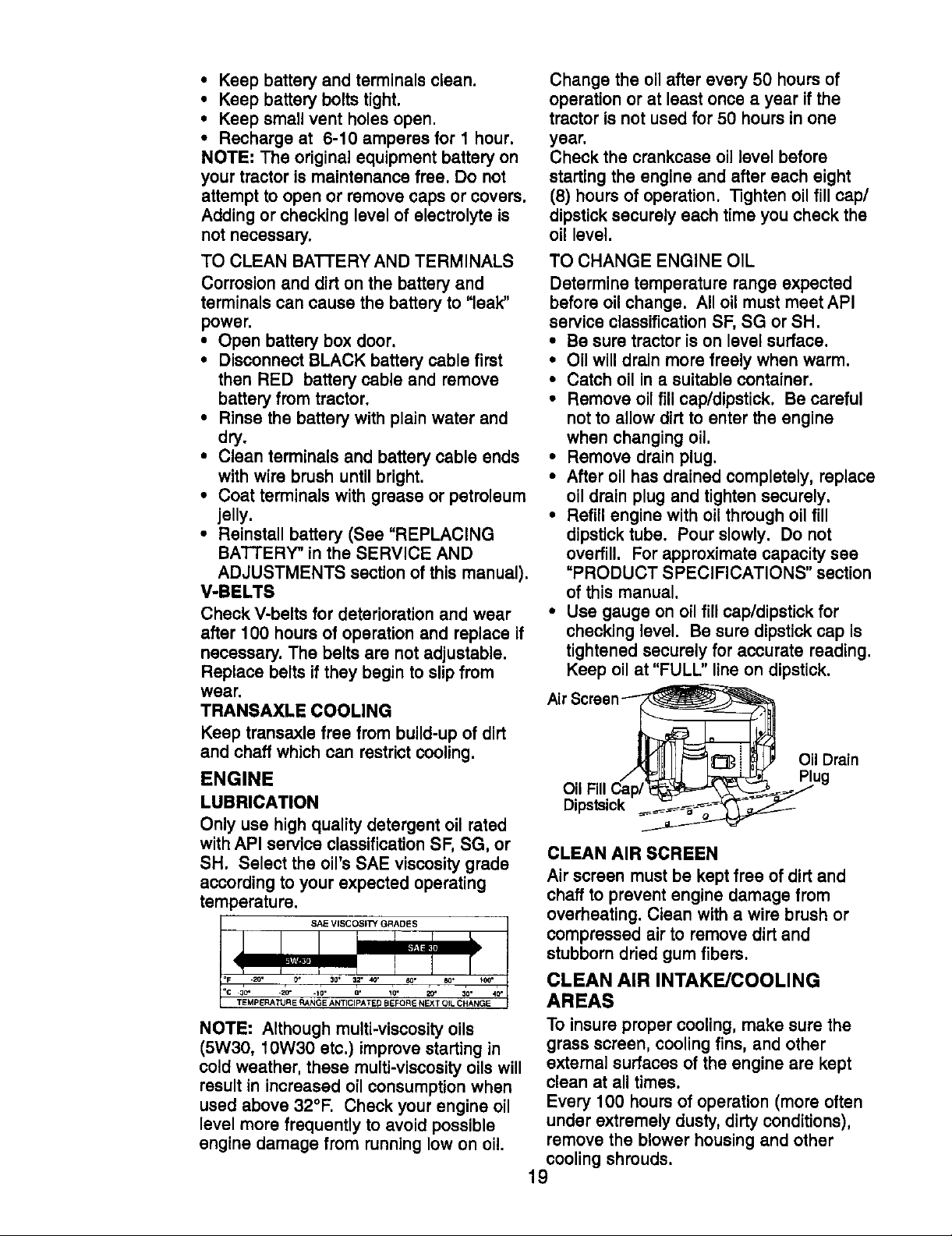
• Use gauge on oil fill cap/dipstick for
checking level. Be sure dipstick cap is
tightened securely for accurate reading.
Keep oil at "FULL" line on dipstick.
Oil Drain
Oil Fill Cap/
Dipstsick
CLEAN AIR SCREEN
Air screen must be kept free of dirt and
chaff to prevent engine damage from
overheating. Clean with a wire brush or
compressed air to remove dirt and
stubborn dried gum fibers.
CLEAN AIR INTAKE/COOLING
AREAS
To insure proper cooling, make sure the
grass screen, cooling fins, and other
external surfaces of the engine are kept
clean at all times.
Every 100 hours of operation (more often
under extremely dusty, dirty conditions),
remove the blower housing and other
cooling shrouds.
19
Page 20
Clean the cooling fins and external
surfaces as necessary. Make sure the
cooling shrouds are reinstalled.
NOTE: Operating the engine with a
blocked grass screen, dirty or plugged
cooling fins, and/or cooling shrouds
removed will cause engine damage due to
overheating.
AIR FILTER
Your engine will not run properly using a
dirty air filter. Clean the foam pre-cleaner
after every 25 hours of operation or every
season. Service paper cartridge every
100 hours of operation or every season,
whichever occurs first.
Service air cleaner more often under dusty
conditions.
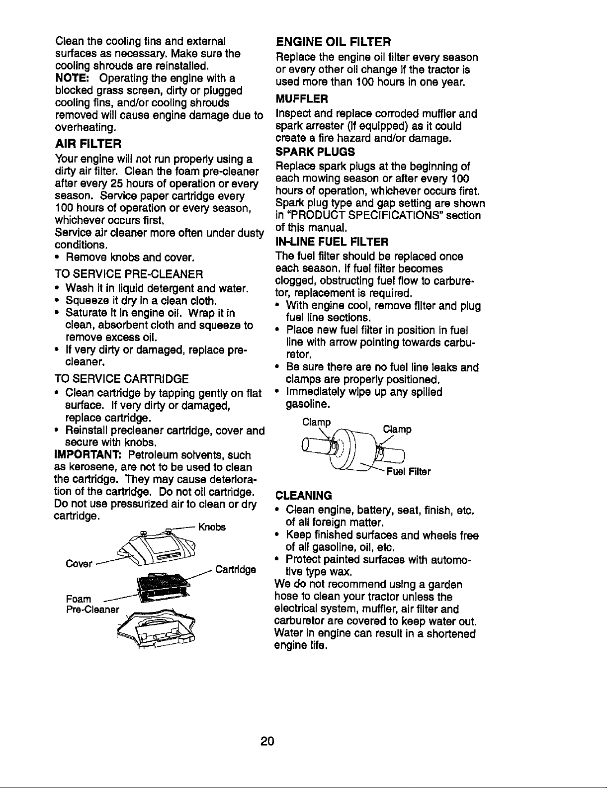
• Remove knobs and cover.
TO SERVICE PRE-CLEANER
• Wash it in liquid detergent and water.
• Squeeze it dry ina clean cloth.
• Saturate it in engine oil. Wrap it in
clean, absorbent cloth and squeeze to
remove excess oil.
• If very dirty or damaged, replace pre-
cleaner.
TO SERVICE CARTRIDGE
• Clean cartridge by tapping gently on flat
surface. Ifvery dirty or damaged,
replace cartridge.
• Reinstall precleaner cartridge, cover and
secure with knobs.
IMPORTANT; Petroleum solvents, such
as kerosene, are not to be used to clean
the cartridge. They may cause deteriora-
tion of the cartridge. Do not oil cartridge.
Do not usa pressurized air to clean or dry
cartridge.
Cover_ Knobs
Foam _ Cartridge
Pre.-Cleana_
ENGINE OIL FILTER
Replace the engine oil filter every season
or every other oil change if the tractor is
used more than 100 hours in one year.
MUFFLER
Inspect and replace corroded muffler and
spark arrester (if equipped) as it could
create a fire hazard and/or damage.
SPARK PLUGS
Replace spark plugs at the beginning of
each mowing season or after every 100
hours of operation, whichever occurs first.
Spark plug type and gap setting are shown
in "PRODUCT SPECIFICATIONS" section
of this manual.
IN-LINE FUEL FILTER
The fuel filter should be replaced once
each season. If fuel filter becomes
clogged, obstructing fuel flow to carbure-
tor, replacement is required.
• With engine cool, remove filter and plug
fuel line sections.
• Place new fuel filter in position in fuel
line with arrow pointing towards carbu-
retor.
• Be sure there are no fuel line leaks and
clamps are properly positioned.
• Immediately wipe up any spilled
gasoline.
_PFiltar
CLEANING
• Clean engine, battery, seat, finish, etc.
of all foreign matter.
• Keep finished surfaces and wheels free
of all gasoline, oil, etc.
• Protect painted surfaces with automo-
tive type wax.
We do not recommend using a garden
hose to clean your tractor unless the
electrical system, muffler, air filter and
carburetor are covered to keep water out.
Water in engine can result in a shortened
engine life.
2O
Page 21
_CAUTION: Before performing any service or adjustments:
• Depress clutch,_rake pedal fully and set parking brake.
• Place gearshift lever in neutral (N) position.
• Place attachment clutch in "DISENGAGED" position.
• Turn ignition key "OFF" and remove key.
• Make sure the blades and all moving parts have completely stopped.
• Disconnect spark plug wire from spark plug and place wire where it cannot come
in contact with plug.
TRACTOR
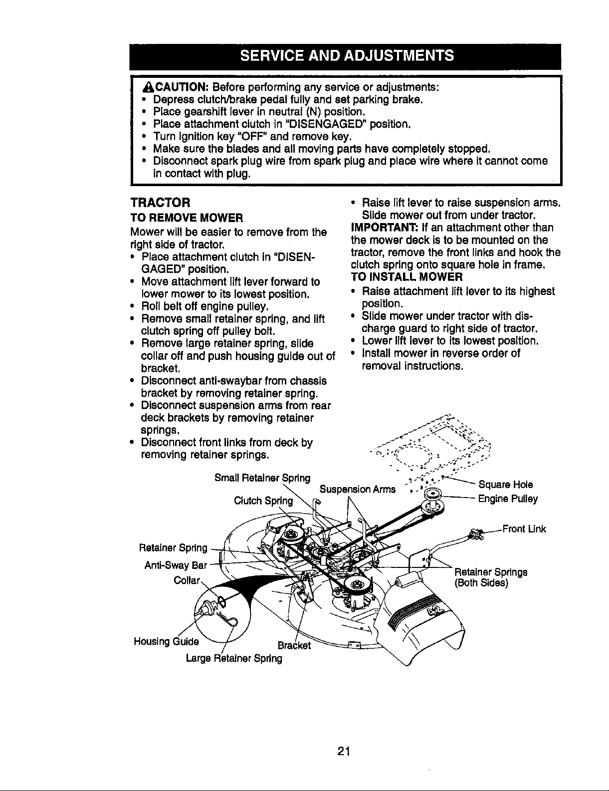
TO REMOVE MOWER
Mower will be easier to remove from the
rightside of tractor.
• Place attachment clutch in "DISEN-
GAGED" position.
• Move attachment lift lever forward to
lower mower to its lowest position.
• Roll belt off engine pulley.
• Remove small retainer spring, and lift
clutch spring off pulley bolt.
• Remove large retainer spring, slide
collar off and push housing guide out of
bracket.
• Disconnect anti-swaybar from chassis
bracket by removing retainer spring.
• Disconnect suspension arms from rear
deck brackets by removing retainer
springs.
• Disconnect front linksfrom deck by
removing retainer springs.
Small Retainer Spring
• Raise lift lever to raise suspension arms.
Slide mower out from under tractor.
IMPORTANT: If an attachment other than
the mower deck isto be mounted on the
tractor, remove the front links and hook the
clutch spring onto square hole in frame.
TO INSTALL MOWER
• Raise attachment lift lever to its highest
position.
• Slide mower under tractor with dis-
charge guard to right side of tractor.
• Lower lift lever to its lowest position.
• Install mower in reverse order of
removal instructions.
Retainer Spring
Anti-Sway Bar
Collar
Housing Guide
Large Retainer Spring
Clutch
Link
(Both Sides)
21
Page 22
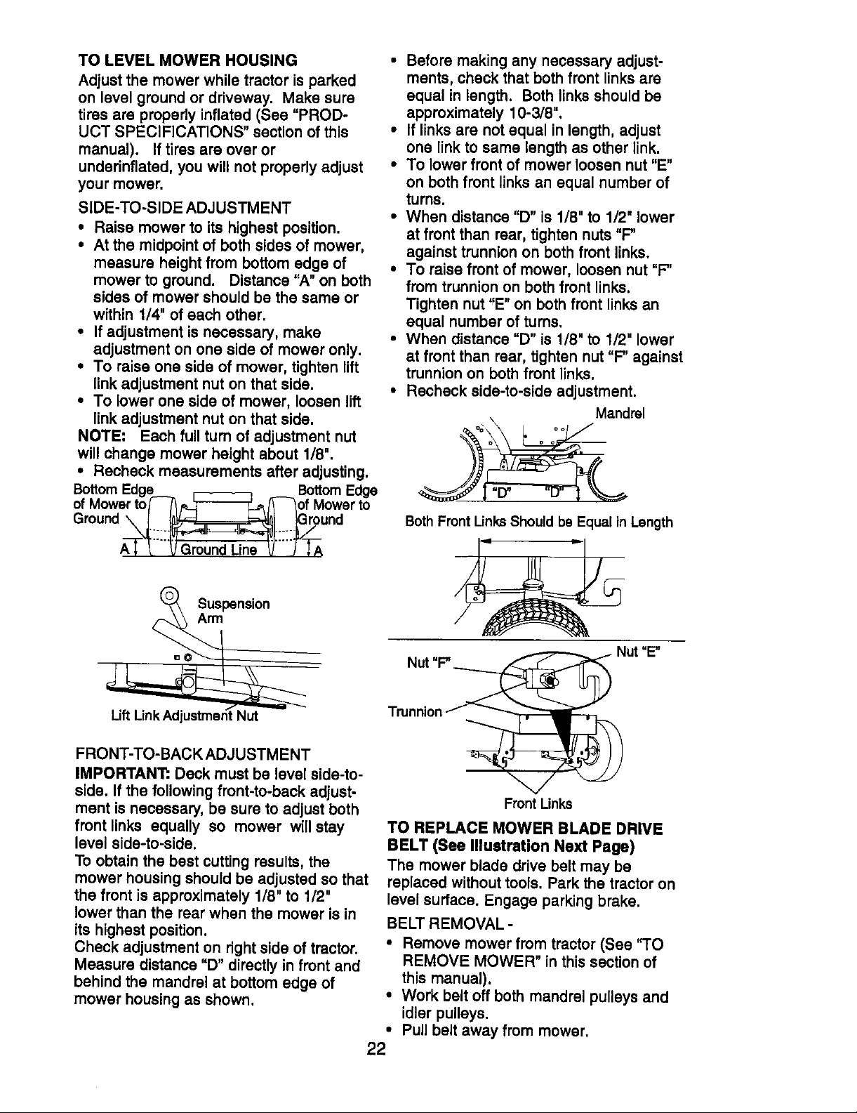
TO LEVEL MOWER HOUSING
Adjust the mower while tractor is parked
on level ground or driveway. Make sure
tires are properly inflated (See "PROD-
UCT SPECIFICATIONS" section of this
manual). If tires are over or
underinflatad, you will not properly adjust
your mower.
SIDE-TO-SIDE ADJUSTMENT
• Raise mower to its highest position.
• At the midpoint of both sides of mower.
measure height from bottom edge of
mower to ground. Distance "A" on both
sides of mower should be the same or
within 1/4" of each other.
• If adjustment is necessary, make
adjustment on one side of mower only,
• To raise one side of mower, tighten lift
link adjustment nut on that side.
• To lower one side of mower, loosen lift
link adjustment nut on that side.
NOTE: Each full turn of adjustment nut
will change mower height about 1/8".
• Recheck measurements after adjusting.
BottomEdge _ __ BottomEdge
ofMowertof-_ _ fT_of Mowerto
Ground\ I l_,uF4 _-_,_l }Ground
• Before making any necessary adjust-
ments, check that both front links are
equal in length. Both links should be
approximately 10-3/8",
• If links are not equal in length, adjust
one link to same length as other link.
• To lower front of mower loosen nut "E"
on both front links an equal number of
turns.
• When distance "D" is 1/8" to 1/2" lower
at front than rear, tighten nuts"F"
against trunnion on both front links.
• To raise front of mower, loosen nut "F"
from trunnion on both front links.
Tighten nut "E"on both front links an
equal number of turns,
• When distance "D" is 1/8" to 1/2" lower
at front than rear, tighten nut "F" against
trunnion on both front links.
• Recheck side-to-side adjustment.
Mandrel
_ r,o
Both Front LinksShould be Equal in Length
Suspension
FRONT-TO-BACK ADJUSTMENT
IMPORTANT=.Deck must be level side-to-
side. If the following front-to-back adjust-
ment is necessary, be sure to adjust both
front links equally so mower will stay
level side-to-side.
To obtain the best cutting results, the
mower housing should be adjusted so that
the front is approximately 1/8" to 1/2"
lower than the rear when the mower is in
its highest position.
Check adjustment on right side of tractor.
Measure distance "D" directly in front and
behind the mandrel at bottom edge of
mower housing as shown,
Front Links
TO REPLACE MOWER BLADE DRIVE
BELT (See Illustration Next Page)
The mower blade drive belt may be
replaced without tools. Park the tractor on
level surface. Engage parking brake,
BELT REMOVAL -
• Remove mower from tractor (See "TO
REMOVE MOWER" in this section of
this manual).
• Work belt off both mandrel pulleys and
idler pulleys.
• Pull belt away from mower.
22
Page 23
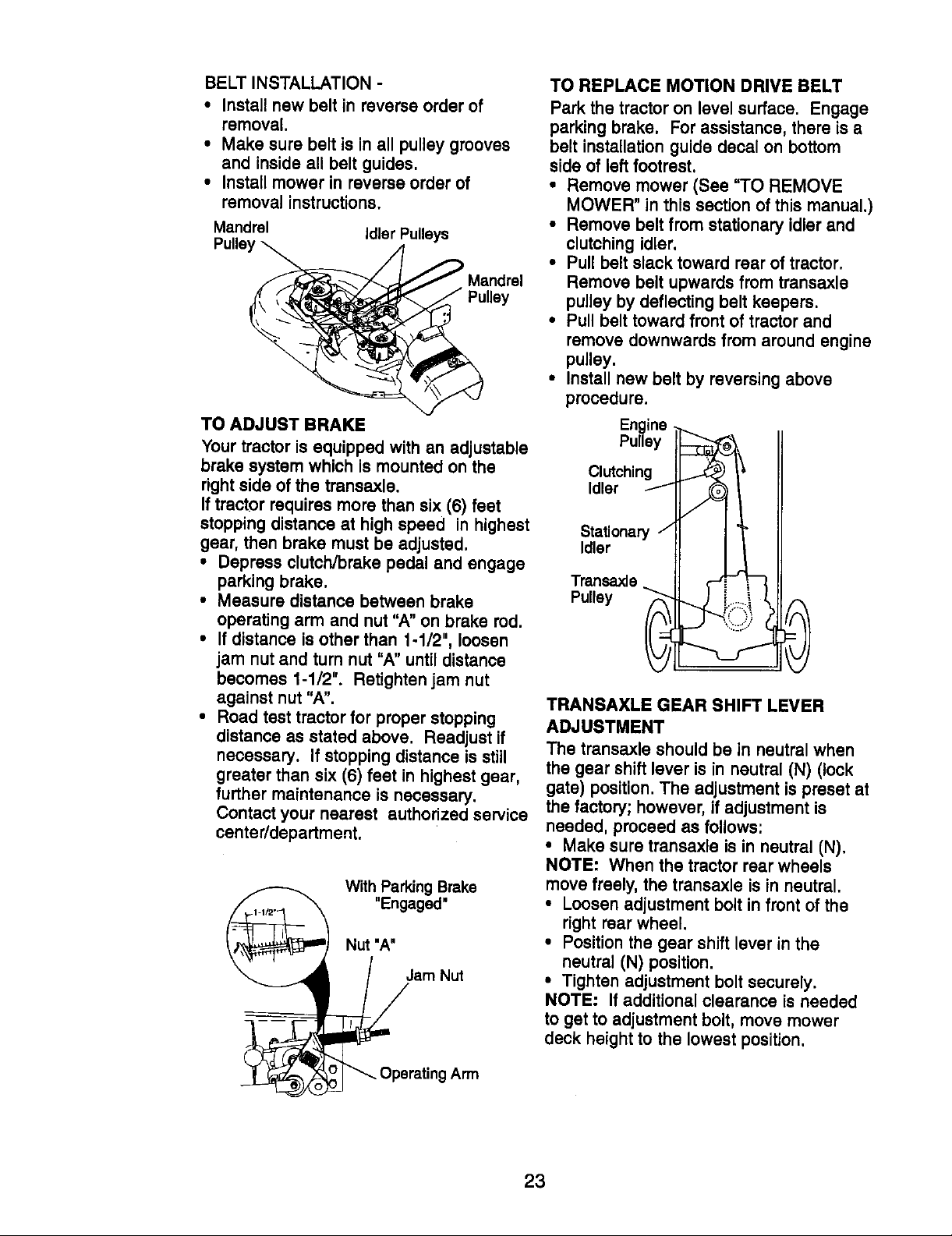
BELT INSTALLATION -
• Install new belt in reverse order of
removal,
• Make sure belt is in all pulley grooves
and inside all belt guides.
• Instatl mower in reverse order of
removal instructions,
Mandrel Idler Pulleys
Pulley
Pulley
TO ADJUST BRAKE
Your tractor is equipped with an adjustable
brake system which is mounted on the
rightside of the transaxle.
Iftractor requires more than six (6) feet
stopping distance at high speed in highest
gear, then brake must be adjusted.
• Depress clutch/brake pedal and engage
parking brake.
• Measure distance between brake
operating arm and nut "A" on brake rod.
• If distance is other than 1-1/2", loosen
jam nut and turn nut "A" untildistance
becomes 1-1/2". Retighten jam nut
against nut "A".
• Road test tractor for proper stopping
distance as stated above. Readjust if
necessary. If stopping distance is still
greater than six (6) feet in highest gear,
further maintenance is necessary.
Contact your nearest authorized service
centerldepartment.
With Parking Brake
"Engaged"
Nut "A"
/am Nut
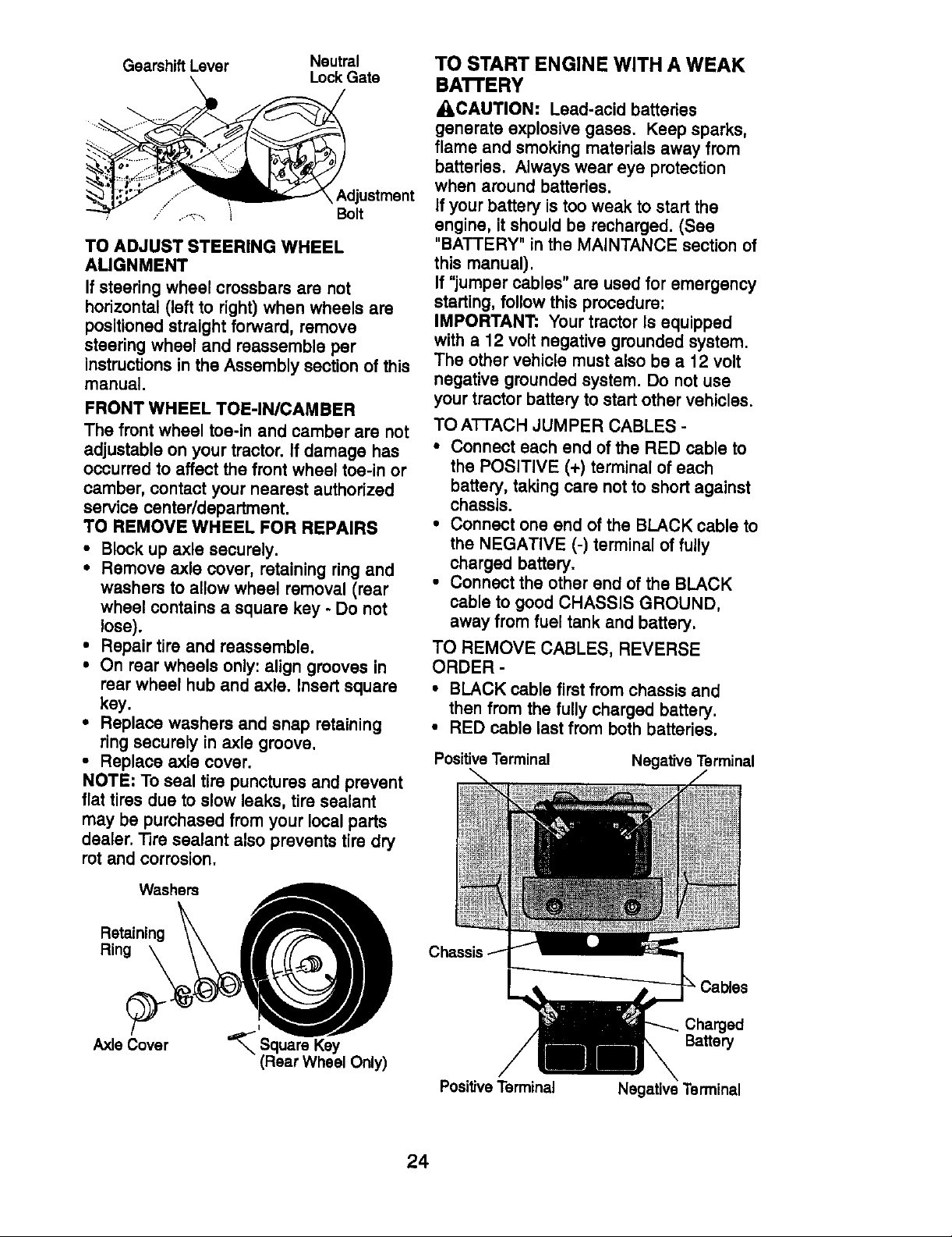
TO REPLACE MOTION DRIVE BELT
Park the tractor on level surface. Engage
parking brake. For assistance, there is a
belt installation guide decal on bottom
side of left footrest.
• Remove mower (See "TO REMOVE
MOWER" in this section of this manual.)
• Remove belt from stationary idlerand
clutching idler.
• Pull belt slack toward rear of tractor.
Remove belt upwards from transaxle
pulley by deflecting belt keepers.
• Pull belt toward front of tractor and
remove downwards from around engine
pulley.
• Install new belt by reversing above
procedure.
Engine
Pulley
Clutching
Idler
Stationary /
Idler
Transaxle
.,._...
Pulley ___
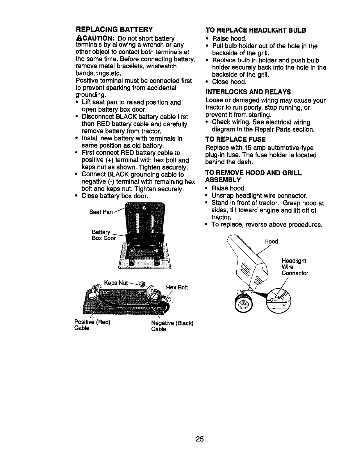
TRANSAXLE GEAR SHIFT LEVER
ADJUSTMENT
The transaxle should be in neutral when
the gear shift lever is in neutral (N) (lock
gate) position. The adjustment is preset at
the factory; however, if adjustment is
needed, proceed as follows:
• Make sure transaxle is in neutral (N).
NOTE: When the tractor rear wheels
move freely, the transaxle is in neutral.
• Loosen adjustment bolt in front of the
right rear wheel.
• Position the gear shift lever in the
neutral (N) position.
• Tighten adjustment bolt securely.
NOTE: If additional clearance is needed
to get to adjustment bolt, move mower
deck height to the lowest position.
D
_Operating Arm
23
Page 24
Gearshift Lever Neutral
Lock Gate
Adjustment
Bolt
TO ADJUST STEERING WHEEL
ALIGNMENT
Ifsteering wheel crossbars are not
horizontal (left to right) when wheels are
positioned straight forward, remove
steering wheel and reassemble per
instructionsin the Assembly section of this
manual.
FRONT WHEEL TOE-IN/CAMBER
The front wheel toe-in and camber are not
adjustable on your tractor. If damage has
occurred to affect the front wheel toe-in or
camber, contact your nearest authorized
service center/department.
TO REMOVE WHEEL FOR REPAIRS
• Block up axle securely.
• Remove axle cover, retaining ring and
washers to allow wheel removal (rear
wheel contains a square key - Do not
lose).
• Repair tire and reassemble.
• On rear wheels only: align grooves in
rear wheel hub and axle. Insert square
key.
• Replace washers and snap retaining
ring securely in axle groove.
• Replace axle cover.
NOTE: To seal tire punctures and prevent
flat tires due to slow leaks, tire sealant
may be purchased from your local parts
dealer. Tire sealant also prevents tire dry
rot and corrosion.
TO START ENGINE WITH A WEAK
BA'I-FERY
ACAUTION: Lead-acid batteries
generate explosive gases. Keep sparks,
flame and smoking materials away from
batteries. Always wear eye protection
when around batteries.
If your battery is too weak to start the
engine, it should be recharged. (See
"BATTERY" in the MAINTANCE section of
this manual).
If "jumper cables" are used for emergency
starting, followthis procedure:
IMPORTANT:. Your tractor Is equipped
with a 12 volt negative grounded system.
The other vehicle must also be a 12 volt
negative grounded system. Do not use
your tractor battery to start other vehicles.
TO ATTACH JUMPER CABLES -
• Connect each end of the RED cable to
the POSITIVE (+) terminal of each
battery, taking care not to short against
chassis.
• Connect one end of the BLACK cable to
the NEGATIVE (-) terminal of fully
charged battery.
• Connect the other end of the BLACK
cable to good CHASSIS GROUND,
away from fuel tank and battery.
TO REMOVE CABLES, REVERSE
ORDER -
• BLACK cable first from chassis and
then from the fully charged battery.
• RED cable last from both batteries.
Positive Terminal
Negative Terminal
Washers
Retaining
Ring
Axle Cover
I
Square Key
(Rear Wheel Only)
PositiveTerminal
24
Ca_es
Cha_ed
Ba_e_
Negative Terminal
Page 25
REPLACING BA'FrERY
_CAUTION: Do not short battery
terminals by allowing a wrench or any
other object to contact both terminals at
the same time. Before connecting battery,
remove metal bracelets, wristwatch
bands,rings,etc.
Positive terminal must be connected first
to prevent sparking from accidental
grounding.
• Lift seat pan to raised position and
open battery box door.
• Disconnect BLACK battery cable first
then RED battery cable and carefully
remove battery from tractor.
• Install new battery with terminals in
same position as old battery.
• First connect RED battery cable to
positive (+) terminal with hex bolt and
keps nut as shown. Tighten securely.
• Connect BLACK grounding cable to
negative (-) terminal with remaining hex
bolt and keps nut. Tighten securely.
• Close battery box door.
Batter
Box Door
TO REPLACE HEADLIGHT BULB
• Raise hood.
• Pull bulb holder out of the hole in the
backside of the grill.
• Replace bulb in holder and push bulb
holder securely back inlo the hole in the
backside of the gdll.
• Close hood.
INTERLOCKS AND RELAYS
Loose or damaged wiring may cause your
tractor to run poorly, stop running, or
prevent it from starting.
• Check wiring. See electrical wiring
diagram in the Repair Parts section.
TO REPLACE FUSE
Replace with 15 amp automotive-type
plug-in fuse. The fuse holder is located
behind the dash.
TO REMOVE HOOD AND GRILL
ASSEMBLY
• Raise hood.
• Unsnap headlight wire conneci.or.
• Stand in front of tractor. Grasp hood at
sides, tilt toward engine and lift off of
tractor.
• To replace, reverse above procedures.
x Bolt
Positive (Red) Negative (BLack)
Cable Cable
od
Headlight
Wirenector
25
Page 26
ENGINE
Maintenance, repair, or replacement of the
emission control devices and systems,
which are being done at the customers
expense, may be performed by any non-
road engine repair establishment or
individual. Warranty repairs must be
performed by an authorized engine
manufacturer's service outlet.
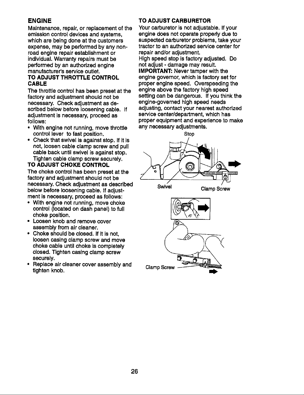
TO ADJUST THROTTLE CONTROL
CABLE
The throttle control has been preset at the
factory and adjustment should not be
necessary. Check adjustment as de-
scribed below before loosening cable. If
adjustment is necessary, proceed as
follows:
• With engine not running, move throttle
control lever to fast position.
• Check that swivel is against stop. If it is
not, loosen cable clamp screw and pull
cable back until swivel is against stop.
Tighten cable clamp screw securely.
TO ADJUST CHOKE CONTROL
The choke control has been preset at the
factory and adjustment should not be
necessary. Check adjustment as described
below before loosening cable. If adjust-
ment is necessary, proceed as follows:
• With engine not running, move choke
control (located on dash panel) to full
choke position.
• Loosen knob and remove cover
assembly from air cleaner.
• Choke should be closed. If it is not,
loosen casing clamp screw and move
choke cable until choke is completely
closed. Tighten casing clamp screw
securely.
• Replace air cleaner cover assembly and
tighten knob.
TO ADJUST CARBURETOR
Your carburetor is not adjustable. Ifyour
engine does not operate properly due to
suspected carburetor problems, take your
tractor to an authorized service center for
repair and/or adjustment.
High speed stop is factory adjusted. Do
not adjust - damage may result.
IMPORTANT: Never tamper with the
engine governor, which isfactory set for
proper engine speed. Overspeeding the
engine above the factory high speed
setting can be dangerous. If you think the
engine-governed high speed needs
adjusting, contact your nearest authorized
service center/department, which has
proper equipment and experience to make
any necessary adjustments.
Stop
Swivel
Clamp Screw
Clamp Screw
26
Page 27
Immediately prepare your tractor for
storage at the end of the season or if the
tractor will not be used for 30 days or
more.
CAUTION: Never store the tractor
with gasoline in the tank inside a building
where fumes may reach an open flame
or spark. Allow the engine to cool before
stonng in any enclosure.
TRACTOR
Remove mower from tractor for winter
storage. When mower is to be stored for
a period of time, clean itthoroughly,
remove all dirt, grease, leaves, etc.
Store in a clean, dry area.
• Clean entire tractor (See "CLEANING"
in the Maintenance section of this
manual).
• Inspect and replace belts, if necessary
(See belt replacement instructionsin
the Service and Adjustments section of
this manual).
• Lubricate as shown in the Maintenance
section of this manual.
• Be sure that all nuts, bolts and screws
are securely fastened. Inspect moving
parts for damage, breakage and wear.
Replace if necessary.
• Touch up all rusted or chipped paint
surfaces; sand lightlybefore painting.
BATTERY
• Fully charge the battery for storage.
• After a period of time in storage,
battery may require recharging.
• To help prevent corrosion and power
leakage during long periods of storage,
battery cables should be disconnected
and battery cleaned thoroughly (see
"TO CLEAN BATI'ERY AND TERMI-
NALS" in the Maintenance section of
this manual).
• After cleaning, leave cables discon-
nected and place cables where they
cannot come in contact with battery
terminals.
• If battery is removed from tractor for
storage, do not store battery directly on
concrete or damp surfaces.
ENGINE
FUEL SYSTEM
IMPORTANT: It is important to prevent
t_uUmdeposits from forming in essential
el system parts such as carburetor, fuel
filter, fuel hose, or tank duringstorage.
Also, experience indicates that alcohol
blended fuels 9called gasohol or using
ethanol or methanol) can attract moisture
which leads to separation and formation
of acids during storage. Acidic gas can
damage the fuel system of an engine
while in storage.
• Drain the fuel tank.
• Start the engine and let it rununtilthe
fuel lines and carburetor are empty.
• Never use engine or carburetor cleaner
products in the fuel tank or permanent
damage may occur.
• Use fresh fuel next season.
NOTE: Fuel stabilizer is an acceptable
alternative in minimizing the formation of
fuel gum deposits during storage. Add
stabilizer to gasoline in fuel tank or
storage container. Always follow the mix
ratio found on stabilizer container. Run
engine at least 10 minutes after adding
stabilizer to allow the stabilizer to reach
the carburetor. Do not drain the gas tank
and carburetor if using fuel stabilizer.
ENGINE OIL
Drain oil (with engine warm) and replace
with clean engine oil. (See "ENGINE" in
the Maintenance section of this manual).
CYLINDER(S)
• Remove spark plug(s).
• Pour one ounce of oil through spark
plug hole(s) into cylinder(s).
• Turn ignition key to "START" position
for a few seconds to distribute oil.
• Replace with new spark plug(s).
OTHER
• Do not store gasoline from one season
to another.
• Replace your gasoline can ifyour can
starts to rust. Rust and/or dirt in your
gasoline willcause problems.
• If possible, store your tractor indoors
and cover it to give protection from
dust and dirt.
• Cover your tractor with a suitable
protective cover that does not retain
moisture. Do not use plastic. Plastic
cannot breathe which allows conden-
sation to form and will cause your
tractor to rust.
IMPORTANT: Never cover tractor while
engine and exhaust areas are still warm.
27
Page 28
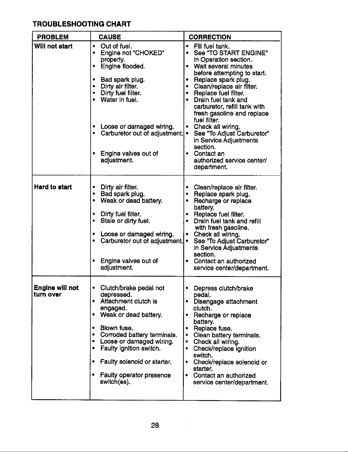
TROUBLESHOOTING CHART
PROBLEM
Will not start
Hard to start
CAUSE CORRECTION
• Out of fuel.
• Engine not"CHOKED"
properly.
• Engine flooded.
• Fill fuel tank.
• See '_O START ENGINE"
in Operation section.
• Wait several minutes
before attempting to start.
• Bad spark plug.
• Dirty air filter.
• Dirty fuel filter,
• Water in fuel.
• Replace spark plug.
• Clean/replace air filter.
• Replace fuel filter.
• Drain fuel tank and
carburetor, refill tank with
fresh gasoline and replace
fuel filter.
• Loose or damaged wiring.
• Carburetor out of adjustment
• Check all wiring.
• See To Adjust Carburetor"
in Service Adjustments
section.
Enginevalvesoutof
adjustment.
• Dirty air filter.
• Bad spark plug.
• Weak or dead battery.
• Contact an
authorized service center/
department.
• Clean/replace air filter.
• Replace spark plug.
• Recharge or replace
battery.
• Dirty fuel filter.
• Stale or dirty fuel.
• Replace fuel filter.
• Drain fuel tank and refill
with fresh gasoline.
• Loose or damaged wiring.
• Carburetor out of adjustment,
• Check all wiring.
• See "1"oAdjust Carburetor"
in Service Adjustments
section.
Engine valves out of
adjustment.
=, Contact an authorized
service center/department.
Engine will not
turn over
Clutch/brake pedal not
depressed.
Attachment clutch is
engaged.
Weak or dead battery.
Blown fuse.
Corroded battery terminals.
Loose or damaged wiring.
Faulty ignition switch.
Faulty solenoid or starter.
!1
Faulty operator presence
switch(es).
28
• Depress clutch/brake
pedal.
• Disengage attachment
clutch.
• Recharge or replace
battery.
• Replace fuse.
• Clean battery terminals.
• Check all wiring.
• Check/replace ignition
switch.
• Check/replace solenoid or
starter.
• Contact an authorized
service center/department.
Page 29

TROUBLESHOOTING CHART
PROBLEM CAUSE CORRECTION
Engine clicks but • Weak or dead battery. • Recharge or replace battery.
will not start • Corroded battery terminals. • Clean battery terminals.
• Loose or damaged wiring. • Check all wiring.
• Faulty solenoid or starter. • Check/replace solenoid or
starter.
Loss of power
• Cutting too much grass/too
fast.
• Throttle in "CHOKE"
position.
• Build-up of grass, leaves
and trash under mower.
i• Dirty air filter.
,• Low oil level/dirty oil.
• Faulty spark plug.
• Dirty fuel filter.
• Stale or dirty fuel.
• Waterin fuel.
• Spark plug wire loose.
• Dirty engine air screen/fins.
• Dirty/clogged muffler.
• Loose or damaged wiring.
• Carburetor out of
adjustment.
• Engine valves out of
adjustment.
• Set in "Higher Cut" position/
reduce speed.
• Adjust throttle control.
• Clean underside of mower
housing.
• Clean/replace air filter.
• Check oil level/change oil.
• Clean and regap or change
spark plug.
• Replace fuel filter.
• Drain fuel tank and refill with
fresh gasoline.
• Drain fuel tank and carburs
tot, refilltank with fresh
gasoline and replace fuel
filter.
• Connect and tighten spark
plug wire.
• Clean engine air screen/fins.
• Clean/replace muffler.
• Check all wiring.
• See "To Adjust Carburetor" in
Service Adjustments section.
• Contact an authorized
service center/department.
Excessive
vibration
Engine continues
to run
when operator
leaves seat
with attachment
clutch engaged
• Worn, bent or loose blade.
• Bent blade mandrel.
• Loose/damaged part(s).
• Faulty operator-safety
presence control system.
29
• Replace blade.
Tighten blade bolt.
• Replace blade mandrel.
• Tighten loose part(s).
Replace damaged parts.
Check wiring, switches and
connections. If not
corrected, contact an autho
rized service center/
department.
Page 30
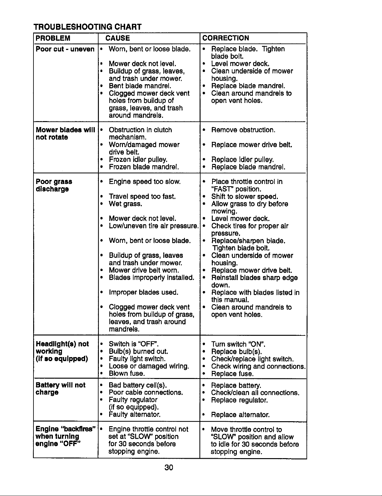
TROUBLESHOOTING CHART
PROBLEM
Poor cut - uneven
Mower blades will
not rotate
Poor grass
discharge
CAUSE
• Worn, bent or loose blade.
• Mower deck not level,
• Buildup of grass, leaves,
and trash under mower.
• Bent blade mandrel.
• Clogged mower deck vent
holes from buildupof
grass, leaves, and trash
around mandrels.
• Obstruction in clutch
mechanism.
• Worn/damaged mower
drive belt.
• Frozen idler pulley.
• Frozen blade mandrel.
• Engine speed too slow.
• Travel speed too fast.
• Wet grass.
• Mower deck not level.
• Low/uneven tire air pressure.
• Worn, bent or loose blade.
• Buildup of grass, leaves
and trash under mower.
• Mower drive belt worn.
• Blades improperly installed.
• Improper blades used.
Clogged mower deck vent
holes from buildup of grass,
leaves, and trash around
mandrels.
CORRECTION
• Replace blade, "13ghten
blade bolt.
• Level mower deck.
• Clean underside of mower
housing,
• Replace blade mandrel.
• Clean around mandrels to
open vent holes.
• Remove obstruction.
• Replace mower drive belt.
• Replace idler pulley.
• Replace blade mandrel.
• Place throttle control in
"FAST" position.
• Shift to slower speed.
• Allow grass to dry before
mowing.
• Level mower deck.
• Check tires for proper air
pressure.
• Replace/sharpen blade.
"nghtenblade bolt.
• Clean underside of mower
housing.
• Replace mower ddve belt.
• Reinstall blades sharp edge
down.
• Replace with blades listed in
this manual.
• Clean around mandrels to
open vent holes.
Headllght(s) not
worklng
(If so equlpped)
Battery will not
charge
Engine "backfires"
when turning
engine "OFF"
• Switch is "OFF".
• Bulb(s) burned out.
• Faulty lightswitch.
• Loose or damaged wiring.
• Blown fuse.
• Bad battery cell(s).
• Poor cable connections.
• Faulty regulator
(if so equipped).
• Faulty alternator.
Engine throttle control not
set at "SLOW" position
for 30 seconds before
stopping engine.
3O
• Turn switch "ON".
• Replace bulb(s).
• Check]replace light switch.
• Check wiring and connections.
• Replace fuse.
• Replace battery.
• Check/clean all connections,
• Replace regulator.
I" Replace alternator.
Move throttle control to
"SLOW" position and allow
to idle for 30 seconds before
stopping engine,
Page 31

SCHEMATIC
(OPTIONAL) '-_ -I _ACK
r AMMETER FUSE STARTER
TRACTOR - - MODEL NUMBER 917.270752
BATTERY
SOLENOID
"""_j ,O ' ,OHm [
_ ........ J
,i_w._;_:/ r r SEATSW,TDH
........!11 _ ,_d-T-b_,
CLUTCH / BRAKE
(PEDAL UP) WHITE
.... _ - - - _ (NOT OCCUPIED)IGNITION
WHITE I i ........ i
_
_111 (_ • SPARK :
i I
FUEL SHUT-OFF
SOLENOID
(IFSO EQUIPPED)
BLACK IGNITION PLUG
uN,, oAP
BROWN
PLUGS ON
TWIN CYL ENGINES)
IGNITION SWITCH
POSITION i CIRCUIT "MAKE"
OFF M+G+A1 NONE
RUN/LIGH1 B+A1 A2+L
RUN B+A1 NONE
START 3+ S + A1 NONE
NON-REMOVABLE
CONNECTIONS HEADLIGHTS
REMOVABLE
CONNECTIONS
WIRING INSULATED CLIPS
NOTE: IF WIRING INSULATED CLIPS WERE REMOVED FOR
SERVICING OF UNIT, THEY SHOULD BE REPLACED TO
PROPERLY SECURE YOUR WIRING.
31
Page 32

ELECTRICAL
TRACTOR - - MODEL NUMBER 917.270752
22
21 •
26
i
s t
t I
rI
i /
I
29
27 i
i
I
32
Page 33

ELECTRICAL
TRACTOR - - MODEL NUMBER 917.270752
KEY PART
NO. NO. DESCRIPTION
1 163465 Battery
2 74760412 BoltHax Hd 1/4-20unc x 3/4
8 156417 Case Battery
16 153664 Switch, Interlock
21 166182 HarnessAsm LightW/4152J
22 4152J Bulb Light#1156
24 4799.1 Cable Battery 6 Ga 11' red
25 146147 Cable Battery 6 Ga w/16 wire red
26 166180 Fuse 15 AMP
27 73510400 Nut Keps Hex 1/4-20 Uric
28 4207J Cable Ground 6 Ga 12"black
29 121305X SwitchPlunger
30 163968 Switch Ign
33 140403 Key Ign
40 170217 Harness Ign
41 711104_8 BoltBIk, Fin Hex 1/4-20 Unc x 1/2
42 131563 Cover Terminal Red
43 145673 Solenoid
45 122822X Ammeter Rectangular 15 Amp
52 141940 ProtectionWire Loop
NOTE: All componentdimensions given In U.S. inches
1inch =25.4 mm
33
Page 34

TRACTOR - - MODEL NUMBER 917.270752
CHASSIS AND ENCLOSURES
28
58 12
31
208
6O
53
54
2O6
/
3
74
208
F
34
Page 35

TRACTOR - - MODEL NUMBER 917.270752
CHASSIS AND ENCLOSURES
KEY PART
NO. NO. DESCRIPTION
1 169830 Chassis
2 169061 Drawbar
3 17060612 Screw 3/8-16 x 3/4
5 155272 Bumper Hood/Dash
9 168337X013 Dash
10 STD533710 Bolt,Carriage 3/8-16 x 3/4
11 155927 Panel, Dash, L.H.
12 145660 ClipTInnerman Grille P/L
13 172107X010 Panel, Dash, R.H.
17 144983X558 Hood Assembly
18 126938X BumperHocd
25 19131312 Washer 13/32 x 13/16 x 12 Gauge
26 STD541437 Nut
28 156725X558 Gdlle w/Lens
29 155217X59g Lens, Gdlle
30 164918X558 Feod/Ftrest
31 139976 Bracket, Fender Support
37 17490508 ScrewThdrol 5/16-18 x 1/2
38 169834 Pivot BracketAssembly, Rear
51 73800400 NutLock w/Insert 1/4-20 UNC
52 19091416 Washer 9/32 x 7/8 x 16 Ga.
53 145201 Bracket Grille PickoffLH
54 161464 Screw Hax Wshd 8-18 x 7/8
55 145202 Bracket Grille Plckoff RH
67 STD522507 Bolt, Fin Hax 1/4-20 UNC x .75
58 162266 Duct intake Air
60 72140606 BoltRdhd Sqnk 3/8-16 UNC x 3/4
64 154798 Dash LowerBTLT
74 STD541437 Nut Crownlock 3/8016 UNC
114 158112 Keeper Belt Rear Lh Stl P930
115 17060620 Screw 3/8-16 x 1-1/4
142 165867 Plate ReinforcementSTLT
143 154966 BracketBwaybar Chassis
144 154207 BracketPnt Footrest STLT
145 156524 Rod PivotChassis/Hood
206 170165 BoltShoulder 5/16-18 TT
207 17670508 Screw Thdrol 5/16-18 x 1/2 Tytt
208 17670608 Screw Thdrol 3/8-16 x 1/2
211 145212 NutHex Flange Lock
212 165919 InsertLensReflective
- - 5479,1 Plug, Button
NOTE:
Allcomponent dimensions given in U.S. Inches
1 inch = 25.4 mm
35
Page 36

GROUND DRIVE
TRACTOR - - MODEL NUMBER 917.270752
_66
51
7O
116
27 151
i
26 27
150
48
51
36
Page 37

TRACTOR -- MODEL NUMBER 917.270752
GROUNDDRIVE
KEY PART KEY PART
NO. NO. DESCRIPTION NO. NO, DESCRIPTION
1 ........ Transaxle (Bee Breakdown) 64 71170764 Bolt, Hex 7116-20x 4 Grade 5
2 146682 Spring, Return, Brake 66 154778 Keeper, Belt, Engine, Fool
3 123666X Pulley, Transexle Proof
4 12000028 Ring, Retainer 70 134683 Guide, Mower Ddve Belt, R.H.
5 121520X Strap, Torque 72 19132012 Washer 13/32 x 1-1/4 x 12 Ga.
6 17060512 Screw 5/16-18 x 3/4 74 137057 Spacer, Axle
8 165866 Rod Shifter Fender STLT 75 121749X Washer 25/32 x 1-1/4 x 16 Ga.
10 STD561210 Pin, Cotter 76 STD581075 E-Ring
11 105701X Washer, Shltt Plate 77 123583X Key, Square 2.0 x .1845/1865
13 74550412 Bolt 1/4-28 UNF W/Patch Gr. 8 78 121748X Washer 25/32 x 1-5/8 x 16 Ga
14 10040400 Washer Lock Hvy Helical 79 STD580025 Key Woodruff
16 STD541431 Nut LockHx W/Ins 80 145090 Arm, Shift
18 STD523710 BoltFin Hex 650 20
19 STD541437 Nut 83 19171216 Washer 17/32x3/4x16Ga.
21 106933X Knob 84 166231 Link Transaxle
22 130804 ROd,Broke 85 150360 Nut, Nylook
24 STD541237 Nut 89 158391X428 Console, Shift, STLT
25 106888X Spdng, Brake Red 90 124346X Nut, Self-Thdlng, Wsh Hd 114
26 STD551037 Washer 96 STD624003 Retainer Spdng 1"
27 STD561210 Pin 112 19091210 Washer 9/32x3/4x 10Ga.
28 145294 Red, Parking Brake 113 127285X Strap Torque 90 Degrees
29 71673 Cap, ParkingBrake 116 72110610 Bolt Rdhd Sqneck
30 169592 Bracket, Transexle 3/8-16 x 1.25
32 STD533107 Bolt 145 74490540 Bolt, Hex FIghd 5/16-18 Gr. 5
34 155071 Shaft Assembly, Foot Pedal 150 165850 Bushing BellcrankGrd. Ddve
35 120183X Beadng, Nylon 151 19133210 Washer 13/32x2x 10 Ga.
36 STD551062 Washer 156 166002 Washer Srrted 5/161Dx 1.125
37 STD571610 Roll Pin 158 165589 Bracket Shift Mount
38 131494 Pulley, Idler, Flat 159 165494 Hub Tapered Flange Shift Lt
39 74760644 Bolt 161 72140406 BoltRdhd Sqnk 1/4-20 x 3/4
40 4470,1 Spacer, Split .395 x .59 Gr.5
41 165838 Keeper, Belt, Idler 162 73680400 Nut Crownlock 1/4-20 Unc
42 19131312 Washer 13/32 x 13/16 x 12Ga. 163 74780416 BoltHex Fin
47 127783 Pulley, Idler,V-Groove, Plastic 1/4-20Unc x 1Gr 5
48 154407 Bellcrank ClutchGrnd Drv SU 164 19091010 Washer 5/8 x .281 x 10 Ga
49 123205X Retainer, Belt 165 165623 Bracket Pivot Lever
50 STD523715 Bolt 166 166880 Screw 5/16-18 x 5/8
51 STD541437 Nut Crown Lock3/8-16 UNC 168 165492 Bolt Shoulder 5/16-18 x .561
52 STD541431 Nut Crown Locks/16-18 UNC 169 165580 Plate Fastening Lt
53 105710X Link,Clutch 170 173898 Keeper BeltTransayJe
55 105709X Spdng, Clutch Retum Pmst/Dana
56 STD523712 BoltFin Hex 3/8-16 x 1-1/4 197 169613 Nyliner Snap-In
57 130801 V-Belt, Ground Ddve 198 169593 Washer Nyliner
59 169691 Keeper, Belt, CenterSpan 202 72110612 BoltCarr. SH
61 17060612 Screw 3/8-16 x 3/4 3/8-16 x 1-1/2 Gr. 5
62 8883R Cover, Pedal
63 140186 Pulley, Engine NOTE: Allcomponent dimensions given In U. S.
Peerless 206-545C 65 STD551143 Washer
5/16-18 x Gr.5 81 165592 Shaft Asm Cross Tapered
3/8-16UNC x I Gr.5 82 165711 Spring, Torsion
Inches 1 inch = 25.4 mm
37
Page 38

TRACTOR - - MODEL NUMBER 917.270752
STEERINGASSEMBLY
_'_ 36
,_..... _-...... i----I
_41
L
62 44
51_54
27
"-_ 22..... "_
i/, 11 4o "/
46
47
25
43
1S
/
/
/
r
38
Page 39

TRACTOR -- MODEL NUMBER 917.270752
STEERING ASSEMBLY
KEY PART
NO. NO. DESCRIPTION
1 139768
2 154427
3 169840
4 169839
5 6265H
6 121748X
7 19272016
8 12000029
9 3366R
10 169832
11 STD55 t 137
13 136518
15 145212
17 156546
18 57079
19 160395
22 165857
23 165851
25 1544O6
26 126847X
27 136874
28 19131416
29 17060612
30 STD561210
32 13O465
36 155099
37 152927
38 139769
39 19133812
40 STD541537
41 100711L
42 145054X428
43 121749X
44 153720
46 121232X
47 6855M
5! STD541431
54 74780520
62 167902
63 STD523710
65 160367
66 1544O4
67 72140618
68 169827
79 19132012
80 74950612
82 169835
85 133835
NOTE:
All component dimensionsgiven In U.S, Inches
1 Inch =25.4 mm
Steedng Wheel
Axle Assembly STMP Dropped STL
Spindle Assembly, L.H.
Splodle Assembly, R.H.
Beadng, Race,Thrust, Hardened
Washer 25/32 x 1-5/8 x 16 Gauge
Washer 27/32 x 1-1/4 x 16 Gauge
Ring, Kilp
Beadng, Steedng Column
Dragllnk
Washer, Lock
Spacer Beadng Axle Front
Nut, Hex Flange Lock
Shaft Assembly, Steedng
Washer, Thrust .515 x .750 x .033
Support,Shaft
Screw, Hex Wsh Hd Ton(
Plttman Shaft Assembly
Bracket,Steedng
Bushing,Link, Drag
Gear, Sector
Washer 13/32 x 7/8 x 16 Gauge
Screw 3/8-16 x 3/4
PinCotter
Rod,Tie
Bushing,Steedng
Screw
Insert,Steedng Wheel
Washer 13/32 x 2-3/8 x 12 Gauge
Nut Lock Center 3/8-24 Unf
Adaptor, Steedng Wheel
Boot,Steedng Shaft
Washer 25/32 x 1-1/4 x 16 Gauge
ExtensionShaft Steering LR.LT
Cap, Spindle
Fitting,Grease
Nut LockHexw/_ns. 5/16-18 UNC
BoltFin Hex 5/16-18 UNCx 1-1/4
KitSteedng Asm Service
Bolt, Rn Hex 3/8-16 UNC x 1 Gr 5
Spacer Brace Axle
Beadng Arm Plttman
BoltRDHD Sqnk 3/8-16 x 2-1/4
Axle, Brace
Washer 13/32 x 1-114 x 12 Ga.
BoltHex Nylon3/8-16 x 3/4
Bracket Susp, Chassis Front
Fastner ChdstmasTree
39
Page 40

ENGINE
_25 14
_"_ 26
TRACTOR - - MODEL NUMBER 917.270752
13
81
29
OPTIONAL EQUIPMENT
Spark Arrester
4O
Page 41

ENGINE
TRACTOR - - MODEL NUMBER 917.270752
KEY PART
NO. NO. DESCRIPTION
1
2
3
4 149723
5 160589
6 159955
8 150176
10 162797
13 165391
14 13280336
15 13200300
16 STD551237
17 17490624
23 169837
25 145996
26 73920600
29 137180
31 109202X
32 158990
33 123487X
37 137040
3 8 .......
40 124028X
44 17670412
45 17000612
46 19091416
62 10040500
72 71070512
81 73510400
NOTE:
162152
17720410
All component dimensionsgiven in U,S. inches
1 Inch =25.4 mm
Control,Throttle
Screw Hex Thd Cut 1/4-20 x 5/8
Engine (See Breakdown) Bdggs
Model407777-0121 -E5
Muffler,Asm. Twin Lo-Tone
Pipe Exhaust Intek 20 RH
Pipe Exhaust Intak 20 LH
Bolt 5/16-18 UNCx3/4
Shield BrowingB&S Intak II
MufflerGasket
Nipple, Pipe
Elbow,Standard 90°, 3/8-18 NPT
Washer, LockExt tooth 3/8
Screw Thdrol 5/8-16 x 1-1/2
Shield, BrowningK)ebdsGuard
ControlChoke
Nut Kaps 3/8-24 UNF
Arrestar, Spark
Tank, Fuel
Cap, Fuel
Clamp, Hose BIk
Line, Fuel
Plug,Oil Drain (See Engine Breakdown)
BushingSnap NylBIk Fuel Une
Screw Hex Wsh Thdrol 1/4-20 x 3/4
Screw Hex Wsh Thdrol 3/8-16 x 3/4
Washer 9/32 x 7/8 x 16 Ga.
Washer Lock Hvy Hlol Spr 5/16
Screw Hex Hd Cap 5/16-18 x3/4
Nut Kaps Hex 1/4-20 Unc
41
Page 42

SEAT ASSEMBLY
TRACTOR - - MODEL NUMBER 917.270752
KEY
NO.
1
2
3
4
5
6
7
8
9
10
11
12
PART KEY PART
NO. DESCRIPTION NO. NO. DESCRIPTION
140123
140551
71110616
19131610
145OO6
STD541437
124181X
17000616
19131614
155925
166369
121246X
Seat 13 121248X
Bracket Pnt Pivot Seat (blk) 14 72050412
BoltFin Hex 3/8-16unc X 1 15 134300
Washer 13/32 X 3/4 X I0 Ga 16 121250X
Clip Push In Hinged 17 123976X
Nut Hex Lock w/Ins 3/8-16 Uric 21 171852
Spdng Seat Cprsn 2 250 BIkZl 22 STD541431
Screw 3/6-16 X 1 24 19171912
Washer 13/32 X 1 X 14 Ga 25 127018X
Pan Phi Seat (blk)
KnobSeat AdjWlngnut
Bracket Pnt MountingSwitch
NOTE: Allcomponent dimensions given in U,S.
inches 1/rich = 25.4 mm
BushingSnap BIk Ny150 Id
BoltRdhd Sht Nk 1/4-20x1-1/2
Spacer Split28 X 96 Zinc
Bpdng Cprsn 127 BlkPnt
Nut Lock 1/4 Lge Fig Gr 5 Zinc
BoltShoulder 5/16-18 Unc-2A
Nut Hex Lock w/Ins 5/16-18
Washer 17/32 X 1-3/16 X12Ga,
BoltShoulder 5/16-18 X 62
42
Page 43

DECALS
TRACTOR - - MODEL NUMBER 917.270752
9
21
KEY PART
NO, NO,
1 156368
2 174321
3 171696
4 171697
5 167049
6 133644
7 138047
8 166887
g 163204
10 156439
13 6
8
14
4 2
KEY PART
DESCRIPTION NO. NO.
Decal,Oper. Instr. 12 146046
Decal, Replacement 13 167329
Decal, Hood, R.H. 14 160396
Decal, Hood, L.H. 20 149516
Decal, HP Engine 21 163207
Decal,Customer Malntenanea - - 138311
Decal,Battery - - 165800X428
Decal, Deck Mower EZ - - 165799X428
Decal,Fender, Craftsman - - 174801
Decal, Fender Danger - - 174802
13 10
2O
12
DESCRIPTION
Decal,V-BeltDriveSchematic
Decal,DashPanel
Decal,V-BaitSchematic
DecalBatteryDngr/PsnEng
Decal,FenderSd.Wht
Decal,LiftHandle
PadFootrestLHSTLT
PadFootrestRHSTLT
Owner'sManual,English
Owner'sManual,Spanish
WHEELS & TIRES
1 ,,.-_.,,__,,._._._
2 _ ;,8 7
KEY PART
NO. NO.
1 59192
2 65139
3 106222X
4,10 5 106732X427
/ 6 278H
3,9 7 9040H
_/ 8 106108X427
4 59904
11 9 122082X
10 7152J
11 104757X
- - 144334
NOTE:All componentdimensionsgiven In U.S. inches
1Inch = 25.4 mm
43
DESCRIPTION
Cap Value Tire
Stem Value
Tlre FTs 15 X 6 0- 6 Ba_tce
Tube Inner Front#35060
Rim Asm 6"frontWhite Service
FittingGrease
Baadng Range
Rim Asm 8"rearWhite Service
Tire R "Is20 X 10-8 Service
Tube Rear 9 5 X 8 Service
Cap Axle BIk 1 50 X 100
Sealant, Tire (10 oz. tube)
Page 44

LIFTASSEMBLY
TRACTOR - - MODEL NUMBER 917.270752
/'///'
5 !'/ i '1
13
13---o_
19
31
32
13
19
13
2O
I'll I'11_
20
15
44
Page 45

LIFT ASSEMBLY
TRACTOR - - MODEL NUMBER 917.270752
K]EY PART
NO. NO, DESCRIPTION
1 159460
2 159471
3 105767X
4 12000002
5 19211621
6 120183X
7 125631X
8 122365X
11 139865
12 139866
13 STD624008
15 173288
16 73350800
17 130171
18 73800800
19 139868
20 163552
31 169865
32 73540600
NOTE=
AllcomponentdimensionsgivenInU.S.Inches
1 inch=25.4mm
Washer Asm Inner Spdng W/Plunger
Shaft Asm. Lift
PinGroove
E Ring#5133-62
Washer 21/32 x 1 x 21 Ga.
Beadng Nylong
Gdp Handle Fluted
ButtonPlunger Read
LinkAsm Lift L.H.
Link Asm lift R.H.
Retainer Spdng
LinkFront
Nut Jam Hex 1/2-13 Unc
TrunnionBIk Zinc
Nut Lock w/Wsh 1/2-13 Unc
Arm Suspension Mower
Retainer Sprtng
Beadng, Pvt. Lift
Nut Crownlock 3/8-24
45
Page 46

MOWER DECK
TRACTOR - - MODEL NUMBER 917.270752
>21
!
16
I
10_
29
_18
18
13--
9_
27
46
Page 47

TRACTOR - - MODEL NUMBER 917.270752
MOWER DECK
KEY PART KEY PART
NO. NO. DESCRIPTION NO. NO.
1 165892 Mower Deck Assembly, 42" 68 144959
2 STD533107 Bolt 92 STD541437
3 138017 Bracket Assembly,Sway Bar, 101 136420
4 165460 Bracket Sway Bar 38/42" Deck 103 19061216
5 STD624008 Retainer Spring 104 STD551110
6 130832 Arm, Suspension, Rear 105 160793
8 850857 Bolt,Hex 3/8-24 x 1.25 Gr. 8 106 2029J
9 STD551137 Washer, Lock 111 155197
10 140296 Washer, Hardened 112 155198
11 134149 Blade, Mulching 113 17060512
12 129895 Baadng, Ball 114 73510500
13 137645 Shaft Assembly, Mandrel, 115 72110504
14 128774 Housing, Mandrel,Vented 118 73930600
15 1t0485X Baadng, Ball,Mandrel 119 19121414
16 140329 Stdppar, Vented Mower Deck 121 143723
18 72140505 Bolt,Cardage 5/16-18 x 5/8 128 153390
19 132827 Bolt,Shoulder 129 19131312
20 159770 Baffle,Vortex 130 STD523710
21 STD541431 Nut Crownlock5/16-18 UNC
22 134753 Stiffaner Bracket 131 STD533710
23 131267 Bracket, Deflector 142 165890
24 105304X Cap, Sleeve 143 157109
25 123713X Spdng, Torsion, Deflector 144 158634
26 110452X Nut, Push 145 165888
27 130968X428 Shield, Deflector 146 165891
28 19111016 Washer 11/32 x5/8 x 16 Ga. 147 131335
29 131491 Rod, Hinge 148 169022
30 157722 Screw Thdrol Washer Head 149 165898
31 129963 Washer, Spacer 150 19091216
32 153535 Pulley, Mandrel 151 169670
33 137266 Nut,Toplock, Ranged 152 169676
34 STD533717 Bolt 153 169674
35 133835 Fastner, Christmas Tree 154 169675
36 131494 Pulley, Idler, Rat 155 169671
37 STD551037 Washer 13/32x13/16x16Ga. 156 169672
40 STD541437 Nut Crownlock 3/8-16 UNC 157 169669
44 140088 Guard, Mandrel, LH. 158 17720410
45 STD624003 Retainer
46 137729 Screw, Thd. Roll 1/4-20 x 5/8 159 72140614
48 133944 Washer, Hardened - - 130794
49 155066 RollerAssembly, Cam Follower
50 131340 Bolt,Shoulder #10-24 Grade 5
51 STD5414f0 Locknut - - 169583
52 139888 Bolt,Shoulder 5/16-18 UNC
53 131845 Arm Assembly, Pad, Brake
54 133943 Washer, Hardened
55 155046 Arm, Idler
56 165723 Spacer, Retainer
59 141043 Guard, TUV Idler
67 149846 Knob Custom Oval
Front 102 71161010
Vented (includes Key 116 4898H
Number 12) 117 165746
NOTE: Allcomponent dimensions given in U.S.
Inches 1 Inch = 25.4 mm
DESCRIPTION
V-Belt
Nut
MulcherCover
Screw
Washer #10
Washer, Lock
LatchAssembly, Bagger
Nut, Weld
Bracket Gauge Wheel I.h
Bracket Gauge Wheel Rh
Screw 5/16-18 x3/4
Nut Keps 5/16-18 Unc
BoltCarr 5/16.Unc x 1/2
BoltShoulder
Wheel Gauge Std
Nut Centerlock 3/8-16 Unc
Washer 3/8 x 7/8 x 4 Ga.
Bracket Extruded Gauge Wheel
Washer Felt
Washer 13/32 x 13/16 x 12Ga.
Bolt, Fin Hex 3/8-16 UNC x 1
Gr. 5
Bolt, Rdhd Sqnk 3/8-16UNC xl
Arm Spring Brake Mower
Bracket Arm Idler42"
Keeper Belt 42" ClutchCable
Pulley Idler Flat
BoltCarriage Idler
Spring Extension
Spring Return Idler
Retainer Spring YellowZinc
Washer 9/32 x 3/4 x 16 Ga.
Bracket Clutch
Cable Clutch42 In
Washer Flat 3/8" Type B
Spring Retainer
Spring Retention Lever
Spacer
Rod Clutch
Screw HaxThd Cut 1/4-20 x 5/
8
BoltRdhd Sqn 3/8-16 Unc x 3/4
Mandrel Assembly (Includes
Key Numbers 8-10, 12-15, 31
and 32)
Mower Deck, Comp(ete
(Standard Deck,Order
Separataly Mulcher Plate and
Gauge Wheel Components,
Key Nos. 101-106 and 111-
121)
47
Page 48

TRACTOR - - MODEL NUMBER 917.270752
PEERLESSTRANSAXLE- - MODELNUMBER206-545C
35A
157
13
157
48
Page 49

TRACTOR - - MODEL NUMBER 917.270752
PEERLESS TRANSAXLE - - MODEL NUMBER 206-545C
KEY PART KEY PART
NO. NO, DESCRIPTION NO. NO.
DESCRIPTION
41A 790079
1 772147 Transaxle Cover 42 792073A
2 780086A Needle Bearing 5/8" 42A 792085A
3 770128 Transaxle Case 43 792075
4 776395 Countershaft 44 790025
5 776409 Output Shaft 45 786066
6 778364 Spur Gear (38 teeth) 46 786086
6A 778369 Spur Gear (15 teeth) 47 774690
7 778330 Spur Gear (11 teeth) 48 774691
8 792180 ShiftKey 49 778356
8A 792047 Woodruff Key #9 50 778338
9 784352 Shift Collar 51 778354
10 784378 Shift Rod & Fork 52 778352
11 778334 Bevel Gear (30 teeth) 53 778350
12 778309 InputBevel Pinion (13 teeth) 54 778346
13 778368 Bevel Gear (13 teeth) 56 778355
(Include. 14) 57 778337
14 778368 Bevel Pinion (13 teeth) 58 778353
(include. 13) 69 778351
15 778370 Ring Gear (43 teeth) 60 778349
17 786188 Drive Pin 61 778345
18 786102 Spacer 1.130 X.695 65 780189
20 792077A Ball 5/16 _dia 66 776422
21 792078 Set Screw 3/8 - 16 x 3/8" 67 776396
22 792079 Spring .310 OD x .625 L 69 792170
25 792073A Screw 1/4 - 20 x 1-1/4" 70 786187
25A 792177 Screw 1/4-20 x 1-3/8" 71 788069
26 792125 Retaining Ring (pkg of 2) 71B 788092
27 792035 Retaining Ring 76 780090
28 788040 Retaining Ring 77 788078A
29 780072 ThrustWasher .627 ID x 79 792144
29A 780160 ThrustWasher .762 ID x
29B 780051 ThrustWasher .762 ID x 85 792154
29C 780199 Anti-Rotation Washer .632 150 788093A
30 780108 Cup Washer 1.127 ID x 157 788088A
31 780001 Flat Washer .750 ID x .056W 900 794712
31A 780195 Fiat Washer .750 ID x .062W
32 788083 Oil Seal 5/8"
34 780194 Bushing .563
35 780193 Flanged Bushing 5 / 8" ID
35A 780197 Flanged Bushing .751
36 790075 Brake Disk
37 790007 Brake Pad Plate
38 799021 Brake Pad (pkg of 2)
39 786026 Dowel Pin
40 792076A Fiat Washer .312 ID x ,059W
•031W 82 778333
.031W 83 778338
.031W 87 788089A
.032W 180 730229A
(Use As Needed)
NOTE: All component dimensions given in U.S,
inches 1 inch = 25.4 mm
Brake Lever
Screw 1/4 - 20 x 1-1/4 _
Screw 1/4 -20x2 1/4"
Locknut 5 / 16 - 24
Brake Pad Holder
Spacer .2625 x 1.0
Brake Lever Bracket
Axle (11-15 / 16" Long)
Axle (16 - 1/2" long)
Spur Gear (29 teeth)
Spur Gear (27 teeth)
Spur Gear (23 teeth)
Spur Gear (19 teeth)
Spur Gear (16 teeth)
Spur Gear (15 teeth)
Spur Gear (11 teeth)
Spur Gear (13 teeth)
Spur Gear (17 teeth)
Spur Gear (21 teeth)
Spur Gear (24 teeth)
Spur Gear (25 teeth)
Flat Washer ,563 ID x .062W
Input Shaft
Shifter & Brake Shaft
Retaining Ring
Spacer .890
Square Cut Ring
"O" Ring
Fiat Washer 1.128 ID x .058W
Inverted Retaining Ring
Spring .430 OD x .5000 L
Bevel & Spur Gear (30 & 13
teeth)
Spur Gear (27 teeth)
Oil Fill Plug
Oil Seal 9 / 16"
Liquid Gasket RTV Silicone
Oil Seal 3/4"
Gear Oil 80W90
Replacement MST - 206-
545C Transaxle
49
Page 50

TRACTOR - - MODEL NUMBER 917.270752
BRIGGS ENGINE-MODEL NUMBER 407777, TYPE NUMBER 0121-E5
029 t 11_
267
216 1R8_:_'
222
REQUIRES SPECIALTOOLS 265r_
TO INSTALL SEE REPAIR _ 718
INSTRUC_ON MANUAL 267
8471523
842
10
?
5_
445
1151sLABELKnT1
3
16
a4_ 555_
163 _
287_
524
lO35_
220
750 J
I 1058 OWNER'S MANUAL J
I 1035 EMISSIONS LABEL ]
41 lo17_
12_=p
552_ 89
691
B65B_
447A ¢P
447
447A
122
51A_
5o_
54 _ 654 o
1027D 551
1033 VALVE OVERHAUL KIT
7_ 51_ 883 _q_/
153
868 _(_
50
Page 51

TRACTOR - - MODEL NUMBER 917.270752
BRIGGSENGINE-MODELNUMBER407777,TYPENUMBER0121-E5
08&
35_,
023 11022 _ 13j_ _....o 211 _ ho23AI _1_11
_,o REQUIRESSPECIALTOOLS
_..J_ ] 240 _ _ l J _" INSTRUCTIONMANUAL.
[ _6011 _ 385_._'_ 788 _,_ 125[ 1169 |
TO,NSTAL'.SOOREPA,R
I_--__/_.I °°'_ 628 =" 163_ _ I"_'-I .r-;--_._.,_ I
9180 _ 415_' I-_11"%_ I
141 I 2311 672 _ I _i 11 '°u_ I
e121CARBURETOR KIT I _, o I "J_" ' t "1 1'
,_, .... 108(_ I _ , _ 13095,
__r_) 11_+ I _ _..._1--_- I---_z _o
51A o_o_ 11421 11_RI[TI II 552 _ 51A_ 105 I [-" _'_ i --I
I'_"LJ II S62Ae _ , _-_.J_
o_2_1 1_o_11 _,2_ _,r_ ',_:_,_1i o4_.
1123_ _6 _ lO4_ I --- [_E,_ I (.-.. I
1123 _ 1124 _ 633 @
276 @ 104_ 552A8 [ r_l
15o_ .2_,_
117,_ 276
_147 I
90;,@
51
Page 52

TRACTOR -- MODEL NUMBER 917.270752
BRIGGS ENGINE-MODEL NUMBER 407777, TYPE NUMBER 0121-E5
74T
1005
75 _)
332 _
934_ 11191'
3631_ 1006 8
720_'
573_
635_
197
_16.__ 334Y
1851 _ I
-k 355 GASKET SET
40
697
52
Page 53

TRACTOR - - MODEL NUMBER 917.270752
BRIGGSENGINE-MODELNUMBER407777,TYPENUMBER0121-E5
KEY PART KEY PART
NO. NO. DESCRIPTION NO. NO. DESCRIPTION
1 690231
2 499585
3 391086
4 690069
5 499587
5A 499595
7 690962
8 499601
9 690937
10 690960
11 690942
12 690945
13 690360
15 690946
16 691046
20 690947
22 690308
23 691053
24 222698
25 499588
499589
499590
499591
26 499604
499605
499606
499607
27 690975
28 499582
29 499583
32 690976
33 499596
34 499597
35 690963
36 690963
40 690964
42 499586
45 690977
45 690978
48 693893
50 690948
51 90949
51A 690950
53 690951
54 690953
73 691055
74 691057
75 691056
89 690283
95 690718
98 499802
104 690984
105 690985
108 690986
117 690232
690989
BCylinderAssembly
* Seal-Oil
*-_- Gasket-CylinderHead
* Gasket-Breather
,* Gasket-Crankcase
* Seal-Oil (PTO Side)
*e_ Gasket-Intake
,ke• Gasket-Intake
• Pin-Float Hinge
• Valve-Float Needle
O Jet-Main (Standard)
ushing-Cylinder
Sump-Engine
Head-CylinderNo. 1
Head-CylinderNo.2
BreatherAssembly
Screw(BreatherAssy.)
Tube-Breather
ScrewICylinder Head)
Plug-OdDrain
Crankshaft
Screw(Engine Sump)
Flywheel
Key-Flywheel
PistonAssembl _d_ O.S.)
PistonAssembl;
PistonAssembl; .020 O.S.)
PistonAssembl; .030 O.S.)
Ring Set-Piston' _td.)
Ring Set-Piston 010 O.S.)
Ring Set-Piston 020 O,S,)
RingS•t-Piston 030 O,S.)
Lock-PistonPin
Pin-Piston
Rod-Connecting
Screw(Connecting Rod)
Valve-Exhaust
Valve-Intake
Spring-Valve(Intake)
Spring-Valve(Exhaust)
Retainer-Valve
Keeper-Valve
Valve Tappet
Cam Shaft
ShortBlock
Manifold-Intake
Stud (Carburetor)
Screw(Intake Manifold)
Screen-Rotating
Screw(Rotating Screen)
Washer (Flywheel)
Plug-Oil
Screw('ThrottleValve)
IdleSpeed Kit
Valve-Choke
Jet-Main (HighAltitude)
121 499811 CarburetorOverhaulKit
122 690952 Spacer-Carburetor
125 499804 Carburetor
130 690993 Valve-Throttle
131 499805 ThrottleShaftKit
133 499806 Float-Carburetor
135 499803 Fuel TransferTube
137 690994 •• Gasket-FloatBow!
141 499807 Choke Shaft Kit
142 499808 • Nozzle-Carburetor
146 94388 Key-'Nming
150 690995 •• Gasket-Nozzle
160 690996 Retainer-Solenoid
163 691001 *_ Gasket-AirCleaner
187 691050 Line-Fuel(Cut to Required
187A 691049 Line-Fuel
188 690960 Screw (ControlBrecket)
192 690083 Adjuster-RockerArm
197 690960 Screw (Back Plate)
209 691018 Spring-Governor
211 691019 Spring-GovernodIdle
212 691020 Link-Throttle
213 691021 Brecket-ChokeControl
216 691022 Link-Choke
219 394346 Gear-Governor
220 690412 Washer (_GovemorLever)
222 691023 Bracket-Control
227 691048 ControlLever-Governor
231 690716 Screw (Choke Valve)
240 691035 Filter-Fuel
250 690957 Retainer-Breather
252 690956 Element-Breather
265 691024 Clamp-Casing
267 695134 Screw (Casing Clamp)
276 690997 ,k•<_ SealingWasher
278 690097 Washer (Gov. ControlLever)
287 690960 Screw (DipstickTube)
304 691004 Housing-Blower
305 691005 Screw_Blower Housing)
309 691262 Motor-Starter
310 691263 Bolt-StarterMotor
311 497608 BrushSet
332 691059 Nut (Flywheel)
333 691060 Armature-Magneto
334 691061 Screw (MagnetoArmature)
337 691043 Spark Plug
358 499889 Gasket Set
363 691062 Flywheel Puller
Included in Engine GasketSet, Raf. No. 358
• Includedin CarburetorOverhaulK_t,Ref, No.
121
• IncludedinCarburetorGasket Set. Ref. No.
977
IncludedinValveOverhaul Kit, Ref. No. 1033
Length)
NOTE: All componentdimensionsgiven in U.S.
inches 1 inch= 25.4 mm
53
Page 54

TRACTOR -- MODEL NUMBER 917.270752
BRIGGSENGINE-MODELNUMBER407777, TYPE NUMBER 0121-E5
KEY PART KEY PART
NO. NO. DESCRIPTION NO. NO. DESCRIPTION
383 690966
385 690960
387 608656
404 690442
418 690999
445 499486
447 691003
447A 690960
462 691261
467 691008
474 691064
501 691185
505 691029
510 497606
513 692024
523 691036
524 691032
525 691037
526 690960
544
552 690552
552A 690553
562 690311
573 691009
579 691029
601 691038
615 690317
616 691045
628 690960
633 690998
635 66538
654 690958
668 691215
672 690234
691 690657
697 690372
703 691010
718 690959
726 499612
729 694123
741 690980
742 690328
750 691033
783 693058
788 691039
789 695050
797 693167
798 690967
801 691283
802 691286
8O3
842 691031
847 499602
851 591234
Wrench-Spark Plug 855 691011 Adapter-Air
Screw(Fuel Pump) 865 691012 Cover-AirGuide
Pump-Fuel 865A 691014 Cover-AirGuide
Washer (GovernorCrank) 865B 691015 Cover-AirGuide
Plata-Cover 868 690968 ,/r_ Seal-Valve
Filtar-AirCleaner Cartridge 871 690969 Bushing-Guide
Screw(Air GuideCover) 877 399916 AlternatorConnector/Wire
Screw(Air GuideCover) 883 690970 * _: Gasket-Exhaust
Washer (Starter Cable) 914 690960 Screw(Rocker Cover)
Knob-AirCleaner 918 694000 Hose-Vacuum
Altamator 929 691003 Screw (Choke Control
Regulator Bracket)
Nut (Gov. ControlLever) 934 691056 Screw (Fan Retainer)
Drive-Starter 943 690589 * O-Ring Seal (Oil Pump
Clutch-Drive Cover)
Dipstick 947 499809
• DipstickTube Seal 965 499613 Oil PumpCover
DipstickTube 967 273638 Filter-Pre-Cleaner
Screw (Regulator) 968 499786 Cover-AirCleaner
Armature-Starter(Service 975 499810 Bowl-Float
with691262 StarterMotor) 977 499812 Gasket Set-Carburetor
Bushing-GovernorCrank 987 691000 Oe Seal-ThrottleShaft
Bushing-GovernorCrank 1005 691243 Fan-Flywheel
Bolt(Gov.ControlLever) 1006 691247 Retainer-Fan
Plata-Back 1013 690954 Nipple-OilFilter
Nut (Starter Cable) 1017 690770 Oi/Pump Screen
Clamp-Hose 1019 690103 Label Kit
Retainer-GovernorShaft 1022 690971 *,_ Gasket-RockerCover
Crank-Govsmor 1023 499599 Cover-Rocker(Cyl. No. 1)
Screw (Fuel Pump Bracket) 1023A 499600 Cover-Rocker(Cyl. No. 2)
• <_ Seal-Choke Shaft 1024 499054
Boot-SparkPlug 1026 690981 Rod-Push (Steel)
Nut (Carburetor) 1026A690982 Rod-Push (Aluminum)
Spacer 1027 492932 Filter-Oil
• v Gasket-CarburetorPlate 1029 690972 RockerArm
• Governor ShaftSeal 1033 499890 Valve OverhaulKit
Screw(Drive Cap) 1035 691042 Shaft-Pump
Clip 1036 695104 EmissionsLabel
Ptn-Looating 1051 691265 Ring-Retaining
Gear-Ring 1058 274277
Wire Clip 1090 691293 Retainer-Brush
Gear-Timing 1100 690973 RockerArm Pivot
E-Ring Retainer 1119 691153 Screw (Alternator)
Screw _Qil Pumpcover) 1123 690987 •€ O-Ring Seal (Solenoid
Gear-Pinion Retainer)
Harness-Wiring Tube
Screw(Brush Retainer) 1126 690991 Screw(Fuel TransferTubs
Screw_RockerArm) 1127 690992 Screw (FloatBowl)
Cap-Drive 1128 690990 • Screw (CarburetorNozzle)
Cap-End 1169 690990 Screw (CarburetorCover
Housing_Sewicewith Plate)
691262 StarterMotor) --- 445777-0027-E2 ReplacementEngine
• Dipstick/l'ubeSeal RPM Settings: Low Speed: 1900-2100
Dipstick/r'ubeAssembly HighSpeed: 3000-3200
TsrminaI-Sparkplug
* IncludedinEngineGasketSet, Ref. No. 358
• IncludedinCarburetorOverhaulKit, Ref. No.
121
<_ IncludedinCarburetorGasket Set, Ref. No.
977
Includedin ValveOverhaul Kit, Rsf. No. 1033
Solenoid-Fuel
Pump-Oil
Owner's Manual
O-Ring Seal-Fuel TransferFuel PumpBracket 1124 690988 •e
NOTE: Allcomponentdimensionsgivenin U.S.
inches 1 inch= 25.4 mm
54
Page 55

55
Page 56

56
Page 57

57
Page 58

58
Page 59

SUGGESTED GUIDE FOR SIGHTING SLOPES FOR SAFE OPERATION
ONLY RIDE UP AND DOWN HILL,
SIGHTING
NOT ACROSS HILL
_ Operate your Tractor up and down the face of slopes (not I
greater than 15 ), never across the face. Make turns gradu-
ally to prevent tipping or loss of control. Exercise extreme
I
I
Page 60

For repair of major brand appliances in your own home...
iiiii ii i i iti_!
.......... 4 MY HOME s" Anytime dayornight ........................ 1 800 ........
.............. (1 800 469--4663) ......
....... www, sears.com .....
no matter who made it, no matter who sold it! ..............
. m m m
L
To bring in products such as vacuums, .......
lawn equipment and electronics for repair, call for ....
iil
the location of your nearest Sears Parts & Repair Center.
ii'iiii!i_!:!!i;
))))))i)il))) www.sears.com
....... call Sears PartsDirectSM! .......
.......... that you need to do it yourself ...........
1-800-488-1222 Aoytirne,dayof night
I
......... 1 800 366 PART 6a 11proCST,
(1.... Boo 366 727_) 7' mdays' -- a we_k" m [.........(' [
........ _.... sears com/partsdirect .........
_iilil
...... ;)
To purchase or inquire about a Sears Service Agreement: ......
1-800-827-6655
........ 7 a.m.- .m. n.- Sat,
Para pedir servicio de reparacibn a domicilio, Au Canada pour service en fran_ais:
y para ordenar piezas con entrega a domicilio: 1-877-LE-FOYER s.
5 p CST, MO
....... 1-888-su-.oGARo" (1-._-_3-.9_)
(1-888-784-6427)
{ l_,_/C_e _t _11s.
© Sears, Roebuck and Co,
174801 05.05.00 RH Printed in U.S.A.
® Registered Trademark / TM Trademark of Sears, Roebuck and Co.
® Marca Registrada / TMMarca de F_orica de Sears, Roebuck and Co,
Page 61

Owner's Manual
ELECTRIC START
42" MOWER
6 SPEED TRANSAXLE
LAWN TRACTOR
Model No.
917.270752
• Safety
• Assembly
• Operation
• Maintenance
• Repair Parts
III I III from preV!oUslybuilt engines; Before You Start the engine; read
_ and underotandthla Owner s Manual
CAUTION:
Read and followall
Safety Rules and Instructions
before operatingthis equipment.
! : .......... ...................... .....
For answers to your questions
about this product, Call:
1-800-659-5917
Sear,= Craftsman Help Line
5 am - 5 pm, Mon - Sat
Sears, Roebuck and Co., Hoffman Estates, IL 60179
Visit our Craftsman website: www.sears.com/craftsman
Page 62

Warranty ................................................ 2
Safety Rules .......................................... 3
Product Specifications .......................... 5
Assembly ............................................... 7
Operation ............................................ 10
Maintenance Schedule ....................... 17
LIMITED TWO YEAR WARRANTY ON CRAFTSMAN RIDING EQUIPMENT PARTS
For two (2) years from the date of purchase, if this Craftsman Riding Equipment is
maintained, lubricated and tuned up according to the instructions in the owner's
manual, Sears will repair or replace, free of charge, any parts found to be defective in
material or workmanship. Warranty service is available free of charge by taking your
Craftsman riding equipment to your nearest Sears Service Center. In-home warranty
service is available but a trip charge will apply. This warranty applies only while this
product is in the United States.
This Warranty does not cover:
• Expendable items which become worn during normal use, such as blades, spark
plugs, air cleaners, belts and oil filters.
• Tire replacement or repair caused by punctures from outside objects, such as nails,
thorns, stumps, or glass.
• Repairs necessary because of operator abuse, including but not limited to, damage
caused by towing objects beyond the capability of the riding equipment, impacting
objects that bend the frame or crankshaft, or over speeding the engine.
• Repairs necessary because of operator negligence, including but not limited to,
electrical and mechanical damage caused by improper storage, failure to use the
proper grade and amount of engine oil, failure to keep the deck clear of flammable
debris, or the failure to maintain the equipment according to the instructions con-
tained inthe owner's manual.
• Engine (fuel system) cleaning or repairs caused by fuel determined to be contami-
nated or oxidized (stale). In general, fuel should be used within thirty (30) days of its
purchase date.
• Riding equipment used for commercial or rental purposes.
LIMITED 90 DAY WARRANTY ON BATI'ERY
For ninety (90) days from date of purchase, if any battery included with this riding
equipment proves defective in material or workmanship and our testing determines the
battery will not hold a charge, Sears will replace the battery at no charge. Warranty
service is available free of charge by taking your Craftsman riding equipment to your
nearest Sears Service Center. In-home warranty service is available but a trip charge
will apply. This warranty applies only while this product is in the United States.
To locate the nearest sears service center or to schedule in-home warranty service,
simply contact sears at 1-800-4-my-home
This Warranty gives you specific legal rights, and you may also have other rights which
may vary from state to state.
Maintenance ....................................... 17
Service and Adjustments .................... 21
Storage ............................................... 27
Troubleshooting .................................. 28
Repair Parts ........................................ 32
Parts Ordering ....................... Back Cover
Sears, Roebuck and Co., D/817 WA, Hoffman Estates, IL 60179
2
Page 63

IMPORTANT: This cutting machine is
capable of amputating hands and feet and
throwing objects. Failure to observe the
following safety instructionscould result in
sedous injury or death.
GENERAL OPERATION
• Read, understand, and follow all
instructions in the manual and on the
machine before starting.
• Only allow responsible adults, who are
familiar with the instructions, to operate
the machine.
• Clear the area of objects such as rocks,
toys, wire, etc., which could be picked
up and thrown by the blade.
• Be sure the area is clear of other people
before mowing. Stop machine if anyone
enters the area.
• Never carry passengers.
• Do not mow in reverse unless absolutely
necessary. Always look down and
behind before and while backing.
• Be aware of the mower discharge
direction and do not point it at anyone.
Do not operate the mower without either
the entire grass catcher or the guard in
place.
• Slow down before turning.
• Never leave a running machine unat-
tended. Always turn off blades, set
parking brake, stop engine, and remove
keys before dismounting.
• Turn off blades when not mowing.
• Stop engine before removing grass
catcher or unclogging chute.
• Mow only in daylight or good artificial
light.
• Do not operate the machine while under
the Influence of alcohol or drugs.
• Watch for traffic when operating near or
crossing roadways.
• Use extra care when loading or unload-
ing the machine into a trailer or truck.
• Data indicates that operators, age 60
years and above, are involved in a large
percentage of riding mower-related
injuries. These operators should
evaluate their ability to operate the
riding mower safely enough to protect
themselves and others from serious
injury.
SLOPE OPERATION
Slopes are a major factor related to loss-
of-control and tipover accidents, which can
result in severe injury or death. All slopes 3
require extra caution. If you cannot back
up the slope or if you feel uneasy on it, do
not mow it.
DO:
• Mow up and down slopes, not across.
• Remove obstacles such as rocks, tree
limbs, etc.
• Watch for holes, ruts, or bumps. Uneven
terrain could overturn the machine. Tall
grass can hide obstacles.
• Use slow speed. Choose a low gear so
that you will not have to stop or shift
while on the slope.
• Follow the manufacturer's recommenda-
tions for wheel weights or counter-
weights to improve stability.
• Use extra care with grass catchers or
other attachments. These can change
the stability of the machine.
• Keep all movement on the slopes slow
and gradual. Do not make sudden
changes in speed or direction.
• Avoid starting or stopping on a slope. If
tires lose traction, disengage the blades
and proceed slowly straight down the
slope.
DO NOT:
• Do nottum on slopes unless necessary,
and then, turn slowly and gradually
downhill, if possible.
• Do not mow near drop-offs, ditches, or
embankments. The mower could
suddenly turn over if a wheel is over the
edge of a cliff or ditch, or if an edge
caves in.
• Do not mow on wet grass. Reduced
traction could cause sliding.
• Do not try to stabilize the machine by
putting your foot on the ground.
• Do not use grass catcher on steep
slopes.
CHILDREN
Tragic accidents can occur if the operator
is not alert to the presence of children.
Children are often attracted to the ma-
chine and the mowing activity. Never
assume that children will remain where
you last saw them.
• Keep children out of the mowing area
and under the watchful care of another
responsible adult.
• Be alert and turn machine off if children
enter the area,
Page 64

• Beforeandwhen backing, look behind
and down for small children.
• Never carry children. They may fall off
and be seriously injured or interfere with
safe machine operation.
• Never allow children to operate the
machine.
• Use extra care when approaching blind
corners, shrubs, trees, or other objects
that may obscure vision.
SERVICE
• Use extra care in handling gasoline and
other fuels. They are flammable and
vapors are explosive.
Use only an approved container.
Never remove gas cap or add fuel
with the engine running. Allow
engine to cool before refueling. Do
not smoke.
Never refuel the machine indoors.
Never store the machine or fuel
container inside where there isan
open flame, such as a water heater.
• Never run a machine inside a closed
area.
• Keep nuts and bolts, especially blade
attachment bolts, tight and keep
equipment in good condition.
• Never tamper with safety devices.
Check their proper operation regularly.
• Keep machine free of grass, leaves, or
other debris build-up. Clean oil or fuel
spillage. Allow machine to cool before
storing.
• Stop and inspect the equipment if you
strike an object. Repair, ifnecessary,
before restarting.
• Never make adjustments or repairs with
the engine running.
• Grass catcher components are subject
to wear, damage, and deterioration,
which could expose moving parts or
allow objects to be thrown. Frequently
check components and replace with
manufacturer's recommended parts,
when necessary.
• Mower blades are sharp and can cut.
Wrap the blade(s) or wear gloves, and
use extra caution when servicing them.
• Check brake operation frequently.
Adjust and service as required.
• Be sure the area isclear of other people
before mowing. Stop machine if anyone
enters the area.
• Never carry passengers or children
even with the blades off.
• Do not mow in reverse unless absolutely
necessary. Always look down and
behind before and while backing.
• Never carry children. They may fall off
and be seriously injured or interfere with
safe machine operation.
• Keep children out of the mowing area
and under the watchful care of another
responsible adult.
• Be alert and turn machine off ifchildren
enter the area.
• Before and when backing, look behind
and down for small children.
• Mow up and down slopes (15 =Max), not
across.
• Remove obstacles such as rocks, tree
limbs, etc.
• Watch for holes, ruts, or bumps. Uneven
terrain could overturn the machine. Ta//
grass can hide obstac/es.
• Use slow speed. Choose a low gear so
that you will not have to stop or shift
while on the slope.
• Avoid starting or stopping on a slope. If
tires lose traction, disengage the blades
and proceed slowly straight down the
slope.
• If machine stops while going uphill,
disengage blades, shift into reverse and
back down slowly.
• Do nottum on slopes unless necessary,
and then, turn slowly and gradually
downhill, ifpossible.
4
Page 65

ALook for this symbol to point out
important safety precautions. It means
CAUTIONIII BECOME AWAREIII YOUR
SAFETY IS INVOLVED.
_CAUTION: In order to prevent acciden-
tal starting when setting up, transporting,
adjusting or making repairs always
disconnect spark plug wire and place wire
where it cannot contact spark plug.
ACAUTION: Do not coast down a hill in
neutral, you may lose control of the tractor.
PRODUCT SPECIFICATIONS
GASOLINE 1.25 GALLONS
CAPACITY UNLEADED
AND TYPE: REGULAR
OIL TYPE SAE 30 (ABOVE 32°F)
API-SF/SG/SH): SAE 5W-30
(BELOW 32°F)
OIL CAPACITY: 4.0 PINTS
SPARK PLUG: CHAMPION RC12YC
GAP: .040")
VALVE INTAKE: .004"-.006"
CLEARANCE: EXHAUST: .004"-.006"
GROUND SPEED FORWARD:
(MPH): 1_ 1.2
2No 1.5
3RD 2.4
4TM 3.5
5TM 4,8
6TM 5.3
REVERSE: 1.5
TIRE PRESSURE: FRONT: 14 PSI
REAR: 10 PSI
CHARGING 16 AMPS@ 3600 RPM
SYSTEM:
BAT-I'ERY: AMP/HR: 28
MIN. CCA: 230
CASE SIZE: U1R
BLADE BOLT 27-35 FT. LBS.
TORQUE:
CONGRATULATIONS on your purchase
of a new Tractor. It has been designed,
engineered and manufactured to give you
the best possible dependability and
performance.
ACAUTION: Tow only the attachments
that are recommended by and comply with
specifications of the manufacturer of your
tractor. Use common sense when towing.
Operate only at the lowest possible speed
when on a slope. Too heavy of a load,
while on a slope, is dangerous. Tires can
lose traction with the ground and cause
you to lose control of your tractor.
AWARNING: The engine exhaust from
this product contains chemicals known to
the State of California to cause cancer,
birth defects, or other reproductive harm.
Should you experience any problem you
cannot easily remedy, please contact your
nearest authorized service center/
department. We have competent, well-
trained technicians and the proper toolsto
service or repair this tractor.
Please read and retain this manual. The
instructionswillenable you to assemble
and maintain your tractor properly. Always
observe the "SAFETY RULES".
REPAIR AGREEMENT
A Repair Agreement is available on this
product. Contact your nearest Sears store
for details.
CUSTOMER RESPONSIBILITIES
• Read and observe the safety rules.
• Follow a regular schedule in maintain-
ing, caring for and using your tractor.
• Follow the instructions under "Mainte-
nance" and "Storage" sections of this
owner's manual.
AWARNING: This tractor is equipped
with an internal combustion engine and
should not be used on or near any
unimproved forest-covered, brush-covered
or grass-covered land unless the engine's
exhaust system is equipped with a spark
arrester meeting applicable local or state
laws (if any). If a spark arrester is used, it
should be maintained in effective working
order by the operator.
In the state of California the above is
required by law (Section 4442 of the
California Public Resources Code). Other
states may have similar laws. Federal laws
apply on federal lands. A spark arrester for
the muffler is available through your
nearest authorized service center/
department (See REPAIR PARTS section
of this manual).
5
Page 66

Steering
Wheel Insert
Steering Wheel
O
(1) Hex Bolt
3/8-16 x I
I_ (1) Large Flat Washer
@
(1) Hex Bolt 5/16-18 x 1-1/4
_ Steering Wheel
' I I , Adapter
17/32 x 1-3/16 x 12 Gauge
i_(1) Knob
Keys
(1) Locknut 5/16-18
Seat
(1) Washer
(1) Lockwasher 318
Steering
Extension
Steering Shaft
Boot
(1) Shoulder
Bolt 5/16-18
Video Casseffe
(2) Keys
Slope Sheet
6
Page 67

Your new tractor has been assembled at the factory with exception of those parts left
unassembled for shipping purposes. To ensure safe and proper operation of your
tractor all parts and hardware you assemble must be tightened securely. Use the
correct tools as necessary to insure proper tightness. Review the video cassette before
you begin.
TOOLS REQUIRED FOR
ASSEMBLY
A socket wrench set willmake assembly
easier. Standard wrench sizes you need
are listed below.
(1) 9/16" wrench (2) 1/2" wrench
(1) Utilityknife (1) Pliers
(1) Tire pressure gauge
When right or left hand is mentioned in
this manual, it means, from your point of
view, when you are in the operating
position (seated behind the steering
wheel).
TO REMOVE TRACTOR FROM
CARTON
UNPACK CARTON
• Remove all accessible loose parts and
parts boxes from shipping carton.
• Cut, from top to bottom, along lines on
all four corners of shipping carton, and
lay panels flat.
• Check for any additional loose parts or
boxes and remove.
BEFORE REMOVING TRACTOR
washer, 3/8 hex bolt and tighten
securely.
• Snap steering wheel insert into center of
steering wheel.
• Remove protective materials from
tractor hood and grill.
IMPORTANT: Check for and remove any
staples inskid that may puncture tires
where tractor is to roll off skid.
Insert
/-_/3/8 HexBolt
y/3/8 Loekwasher
_ LargeRat
Wheel )__._Boot
Extension Tabs
Shaft
v.,_..
_--_ Adapter
FROM SKID
ATTACH STEERING WHEEL
L5/loc6nut-_'_:__ 5/16Bo,t
ASSEMBLE EXTENSION SHAFTAND
BOOT
• Slide extension shaft onto lower
steering shaft. Align mounting holes in
extension and lower shafts and install 5/
16 hex bolt and Iocknut. Tighten
securely.
• Place tabs of steering boot over tab
slots in dash and push down to secure.
INSTALL STEERING WHEEL
• Position front wheels of the tractor so
they are pointing straight forward.
• Remove steering wheel adapter from
steering wheel and slide adapter onto
steering shaft extension.
• Position steering wheel so cross bars
are horizontal (left to right) and slide
inside boot and onto adapter.
• Assemble large flat washer, 3/8 lock
Lower , . -'---
Steering _ ' "" ' Tabs
Shaft __ Slots
_ lit
HOW TO SET UP YOUR TRACTOR
CHECK BATTERY
Liftseat pan to raised position and open
battery box door.
If this battery is put into service after
month and year indicated on label (label
located between terminals) charge
battery for minimum of one hour at 6-10
amps. (See "BATTERY" in Maintenance
section of this manual for charging
instructions).
7
Page 68

BatteryBox
Door
INSTALL SEAT
Adjust seat before tightening adjustment
knob.
• Remove adjustment knob and flat
washer securing seat to cardboard
packing and set aside for assembly of
seat to tractor.
• Pivot seat upward and remove from the
cardboard packing. Remove the
carboard packing and discard.
•Placa seat on seat pan and assemble
shoulder bolt. Tighten shoulder bolt
securely.
• Assemble adjustment knob and fiat
washer loosely. Do not tighten.
• Lower seat into operating positionand
sit on seat.
• Slide seat until a comfortable position is
roached which allows you to press
clutch/brake pedal all the way down.
• Get off seat without moving Its adjusted
position.
• Raise seat and tighten adjustment knob
securely.
Seat
SeatPan
Shoulder _ _ _._, _/
Bolt _ ,._
TO ROLL TRACTOR OFF SKID (See
Operetlon section for location and
function of controls)
• Press liftlever plunger and raise
attachment lift lever to its highest
position.
• Release parking brake by depressing
clutch/brake pedal.
• Place gearshift lever in neutral (N)
position.
• Roll tractor forward off skid.
• Remove banding holding discharge
guard up against tractor.
TO DRIVE TRACTOR OFF SKID (See
Operation section for location and
function of controls)
_WARNING: Before starting, read,
understand and follow all instructionsin
the Operation section of this manual. Be
sure tractor is in a well-ventilated area. Be
sure the area in front of tractor is clear of
other people and objects.
• Be sure all the above assembly steps
have been completed.
• Check engine oil level and fillfuel tank
with gasoline.
• Sit on seat in operating position,
depress clutch/brake pedal and set the
parking brake.
• Place gear shift lever in neutral (N)
position.
• Press lift lever plunger and raise
attachment lift lever to Its highest
position.
• Start the engine. After engine has
started, move thro_tlecontrol to idle
position.
• Depress clutch/brake pedal into full
"BRAKE" position and hold. Move
gearshift lever to 1st gear.
• Slowly release clutch/brake pedal and
slowly drive tractor off skid.
• Apply brake to stop tractor, set parking
brake and place gearshift lever in
neutral position.
• Turn ignitionkey to "OFF" position.
Continue with the instructions that follow.
Adjus_tm_nt_Flat Washer
Knob
NOTE: You may now rollor drive your
tractor off the skid. Follow the appropriate
instruction below to remove the tractor
from the skid.
INSTALL MULCHER PLATE
(If previously removed)
• Raise and hold deflector shield in
upright position.
• Piece front of mulcher plate over front of
mower deck opening and slide Into
place, as shown.
• Hook front latch into hole on front of
mower deck.
• Hook rear latch into hole on back of
mower deck.
8
Page 69

_,CAUTION: Do not remove deflector
shield from mower. Raise and hold shield
when attaching mulcher plate and allow it
to rest on plate while in operation.
Deflector
Shield_('\ _ Mulcher
( t
Hoo_
TO CONVERT TO BAGGING OR
DISCHARGING
Simply remove mulcher plate and store in
a safe place. Your mower is now ready for
discharging or installation of optional grass
catcher accessory.
NOTE: It is not necessary to change
blades. The mulcher blades are designed
for discharging and bagging also.
CHECK TIRE PRESSURE
The tires on your tractor were overinflated
at the factory for shipping purposes.
Correct tire pressure is important for best
cutting performance.
• Reduce tire pressure to PSI shown in
"PRODUCT SPECIFICATIONS" section
of this manual.
CHECK DECK LEVELNESS
For best cutting results, mower housing
should be properly leveled. See "TO
LEVEL MOWER HOUSING" in the
Service and Adjustments section of this
manual.
CHECK FOR PROPER POSITION OF
ALL BELTS
See the figures that are shown for
replacing motion and mower blade drive
belts in the Service and Adjustments
section of this manual, Verify that the belts
are routed correctly,
CHECK BRAKE SYSTEM
After you learn how to operate your
tractor, check to see that the brake is
properly adjusted. See "TO ADJUST
BRAKE" in the Service and Adjustments
section of this manual.
v' CHECKLIST
Before you operate and enjoy your new
tractor, we wish to assure that you receive
the best performance and satisfaction from
this quality product.
Please review the following checklist:
/ All assembly instructionshave been
completed.
/ No remaining loose parts in carton.
,/Battery is properly prepared and
charged.(Minimum 1 hour at 6 amps).
,/Seat is adjusted comfortably and
tightened securely.
,/All tires are properly inflated. (For
shipping purposes, the tires were
overinflated at the factory).
,/Be sure mower deck is properly leveled
side-to-side/front-to-rear for best cutting
results. (Tires must be properly inflated
for leveling).
,/Check mower and drive belts. Be sure
they are routed properly around pulleys
and inside all belt keepers.
,/Check wiring. See that all connections
are still secure and wires are properly
clamped.
While learning how to use your tractor, pay
extra attention to the following important
items:
4 Engine oil isat proper level.
/ Fuel tank is filled with fresh, clean,
regular unleaded gasoline.
/ Become familiar with all controls - their
location and function. Operate them
before you start the engine.
4"Be sure brake system is in safe operat-
ing condition.
9
Page 70

These symbols may appear on your tractor or in literature supplied withthe product,
Learn and understand their meaning,
BATTERY CAUTION OR
WARNING
ENGINE ON ENGINE OFF OIL PRESSURE
REVERSE FORWARD FAST SLOW
LIGHTSONO%_MP
FUEL CHOKE MOWER HEIGHT PARKING BRAKE UNLOCKED MOWER LIFT
LOCKED
R N H L
A'N'ACHMENT REVERSE NEUTRAL HIGH LOW PARKING BRAKE
CLUTCH ENGAGED
A37"ACHMENT KEEP AREA CLEAR SLOPE HAZARDS
IGNITION CLUTCH DISENGAGED (SEE SAFETY RULES SECTION)
DANGER, KEEP HANDS AND FEET AWAY
FREE WHEEL
(Automatic Models only)
10
Page 71

KNOW YOUR TRACTOR
READ THIS OWNER'S MANUAL AND SAFETY RULES BEFORE
OPERATING YOUR TRACTOR
Comparethe illustrationswithyourtractortofamiliarizeyourselfwiththe locationsof
variouscontrolsandadjustments.Save thismanualforfuturereference,
Attachment Light
Ammeter Switch
Clutch Lever Ignition Switch
Choke Control
Throttle
Control
Clutch/
Brake
Pedal
Lift Lever
Plunger
Attachment
Lift Lever
o
O
Height
Adjustment
Indicator
Parking Brake
Gearshift
Lever
Our tractors conform to the safety standards of the American
National Standards Institute.
ATTACHMENT CLUTCH LEVER: Used
to engage the mower blades, or other
attachments mounted to your tractor.
LIGHT SWITCH: Turns the headlights on
and off.
THROTTLE CONTROL: Used for starting
and controlling engine speed,
CHOKE CONTROL: Used when starting
a cold engine.
CLUTCH/BRAKE PEDAL: Used for
declutching and braking the tractor and
starting the engine.
PARKING BRAKE: Locks clutch/brake
pedal into the brake position.
GEARSHIFT LEVER: Selects the speed
and direction of tractor.
ATTACHMENT LIFT LEVER: Used to
raise, lower, and adjust the mower deck or
other attachments mounted to your
tractor.
LIFT LEVER PLUNGER: Used to release
attachment liftlever when changing its
position.
IGNITION SWITCH: Used for starting and
stopping the engine.
AMMETER: Indicates battery charging
(+) or discharging (-).
11
Page 72

The operation of any tractor can result in foreign objects thrown into the
eyes, which can result in severe eye damage. Always wear safety
glasses or eye shields while operating your tractor or performing any
adjustments or repairs. We recommend a wide vision safety mask over
spectacles, or standard safety glasses.
HOW TO USE YOUR TRACTOR
TO SET PARKING BRAKE
Your tractor is equipped with an operator
presence sensing switch. When engine
is running,any attempt by the operator to
leave the seat without first setting the
parking brake willshut off the engine.
• Depress clutch/brake pedal into full
"BRAKE" position and hold.
• Place parking brake lever in "EN-
GAGED" position and release pressure
from clutch/brake pedal. Pedal should
remain in "BRAKE" position. Make sure
parking brake will hold tractor secure.
Choke Control
Throttle _
Control
Clutch/Brak=
Pedal "Drive'_
'Disengaged"
Position
STOPPING
MOWER BLADES -
• To stop mower blades, move attach-
ment clutch lever to "DISENGAGED"
position.
GROUND DRIVE -
• To stop ground drive, depress clutch/
brake pedal intofull "BRAKE" position.
• Move gearshift lever to neutral (N)
position.
ENGINE -
• Move throttle control to slow position.
NOTE: Failure to move throttle control to
slow position and allowing engine to idle
before stopping may cause engine to
"backfire".
AttachmentClutchLever
"Engaged"Position
_-_ //Ignition Key
I-_ y. "Disengaged"
_ yPosition
_,,,-_,, I ParkingB_ake
.". "_',__ / Engaged
Position
"Brake'
Position
• Turn ignition key to "OFF" position and
remove key. Always remove key when
leaving tractor to prevent unauthorized
use.
• Never use choke tostopengine.
IMPORTANT: Leavingtheignitionswitch
inany positionotherthan"OFF" willcause
thebatterytobe discharged,(dead).
NOTE: Under certainconditionswhen
tractorisstandingidlewiththeengine
running,hotengineexhaustgases may
cause "browning"ofgrass.To eliminate
thispossibility,always stopenginewhen
stopping tractor on grass areas.
ACAUTION: Always stop tractor
completely, as described above, before
leaving the operator's position;to empty
grass catcher, etc.
TO USE THROTTLE CONTROL
Always operate engine at full throttle.
• Operating engine at less than full
throttle reduces the battery charging
rate.
• Full throttle offers the best bagging and
mower performance.
TO USE CHOKE CONTROL
Use choke control whenever you are
starting a cold engine. Do not use to start
a warm engine.
• To engage choke control, pull knob out.
Slowly push knob in to disengage.
TO MOVE FORWARD AND BACKWARD
The direction and speed of movement is
controlled by the gearshift lever.
• Start tractor with clutch/brake pedal
depressed and gearshift lever in neutral
(N) position.
• Move gearshift lever to desired posi-
tion.
• Slowly release clutch/brake pedal to
start movement.
IMPORTANT: Bring tractor to a complete
stop before shiftingor changing gears.
Failure to do so willshorten the useful life
of your transaxle.
12
Page 73

TO ADJUST MOWER CUTTING
HEIGHT
The position of the attachment lift lever
determines the cutting height.
• Grasp liftlever.
• Press plunger with thumb and move
lever to desired position.
The cutting height range is approxi-
mately 1-1/2 to 4". The heights are
measured from the ground to the blade tip
with the engine not running. These
heights are approximate and may vary
depending upon soil conditions, height of
grass and types of grass being mowed.
• The average lawn should be cut to
approximately 2-1/2 inches during the
cool season and to over 3 inches during
hot months. For healthier and better
looking lawns, mow often and after
moderate growth.
• For best cutting performance, grass over
6 inches in height should be mowed
twice. Make the first cut relatively high;
the second to desired height.
TO ADJUST GAUGE WHEELS
Gauge wheels are properly adjusted
when they are slightly off the ground when
mower is at the desired cutting height in
operating position. Gauge wheels then
keep the deck in proper position to help
prevent scalping in most terrain conditions.
• Adjust gauge wheels with tractor on a
flat level surface.
• Adjust mower to desired cutting height
(See 'TO ADJUST MOWER CUTTING
HEIGHT" in the Operation section of this
manual).
• With mower in desired height of cut
position, gauge wheels should be
assembled so they are slightly off the
ground. Install gauge wheel in appropri-
ate hole with shoulder bolt, 3/8 washer,
and 3/8-16 Iocknut and tighten securely.
• Repeat for opposite side installing
gauge wheel in same adjustment hole.
GaugeWheel .2_-_-_,_
Mounting\ _F f _
Bracket "'_ \ _i_ _
TO OPERATE MOWER
Your tractor is equipped with an operator
presence sensing switch. Any attempt by
the operator to leave the seat with the
engine running and the attachment clutch
engaged will shut off the engine.
• Select desired height of cut.
• Start mower blades by engaging
attachment clutch control.
• TO STOP MOWER BLADES - disen-
gage attachment clutch control.
ACAUTION: Do not operate the mower
without either the entire grass catcher, on
mowers so equipped, or the deflector
shield in place.
Attachment Clutch
Lever "Engaged"
Position Position
• Attachment Uft Lever
High Position
Low
TO OPERATE ON HILLS
• kCAUTION: Do not drive up or down hills
with slopes greater than 15° and do not
drive across any slope, A slope guide at
the back of your manual is provided for
your use.
• Choose the slowest speed before
starting up or down hills.
• Avoid stopping or changing speed on
hills.
• If slowing is necessary, move throttle
control lever to slower position.
• If stopping is absolutely necessary, push
clutch/brake pedal quickly to brake
position and engage parking brake.
• Move gearshift lever to lst gear. Be
sure you have allowed room for tractor
to rollslightly as you restart movement.
• To restart movement, slowly release
parking brake and clutch/brake pedal.
• Make all turns slowly.
3/8 Washer __...E-_ ._ "J Shoulder
GaugeWheel_ _ Bolt
13
Page 74

TO TRANSPORT
• Raise attachment lift to highest position
with attachment lift control.
• When pushing or towing your tractor, be
sure gearshift lever is in neutral (N)
position.
• Do not push or tow tractor at more than
five (5) MPH.
NOTE: To protect hood from damage
when transporting your tractor on a truck
or a trailer, be sure hood is closed and
secured to tractor. Use an appropriate
means of tying hood to tractor (rope, cord,
etc.).
TOWING CARTS AND OTHER
A'I-I'ACHMENTS
Tow only the attachments that are
recommended by and comply with
specifications of the manufacturer of your
tractor. Use common sense when towing.
Too heavy of a load, while on a slope, is
dangerous. "liros can lose traction withthe
ground and cause you to lose control of
your tractor.
BEFORE STARTING THE ENGINE
CHECK ENGINE OIL LEVEL
• The engine in your tractor has been
shipped, from the factory, already filled
with summer weight oil.
• Check engine oil with tractor on level
ground.
• Remove oil fill cap/dipstick and wipe
clean, reinsert the dipstick and screw
cap tight, wait for a few seconds,
remove and read oil level. If necessary,
add oil until "FULU' mark on dipstick is
roached. Do not overfill.
• For cold weather operation you should
change oil for easier starting (See "OIL
VISCOSITY CHART" in the Mainten-
ance section of this manual).
• To change engine oil, see the Mainten-
ance section in this manual.
ADD GASOLINE
• Fill fuel tank. Use fresh, clean, regular
unleaded gasoline with a minimum of
87 octane. (Use of leaded gasoline will
increase carbon and lead oxide
deposits and reduce valve life). Do not
mix oil with gasoline. Purchase fuel in
quantities that can be used within 30
days to assure fuel freshness.
IMPORTANT: When operating in tem-
peraturos below 32°F(0°C), use fresh,
clean winter grade gasoline to help insure
good cold weather starting.
_WARNING: Experience indicates that
alcohol blended fuels (called gasohol or
using ethanol or methanol) can attract
moisture which leads to separation and
formation of acids duringstorage. Acidic
gas can damage the fuel system of an
engine while in storage. To avoid engine
problems, the fuel system should be
emptied before storage of 30 days or
longer. Drain the gas tank, start the
engine and let it run until the fuel lines
and carburetor are empty. Use fresh fuel
next season. See Storage Instructionsfor
additional information. Never use engine
or carburetor cleaner products in the fuel
tank or permanent damage may occur.
ACAUTION: Fill to bottom of gas tank
filler neck. Do not overfill. Wipe off any
spilled oil or fuel. Do not store, spill or use
gasoline near an open flame.
14
Page 75

TO START ENGINE
When starting the engine for the firsttime
or if the engine has run out of fuel, it will
take extra cranking time to move fuel from
the tank to the engine.
• Sit on seat in operating position,
depress clutch/brake pedal and set
parking brake.
• Place gear shift lever in neutral (N)
position.
• Move attachment clutch to "DISEN-
GAGED" position.
• Move throttle control to fast position
• Pull choke control out for a cold engine
start attempt. For a warm engine start
attempt the choke control may not be
needed.
NOTE: Before starting, read the warm and
cold starting procedures below.
• Insert key into ignitionand turn key
clockwise to "START" position and
release key as soon as engine starts.
Do not run starter continuouslyfor more
than fifteen seconds per minute. If the
engine does not start after several
attempts, push choke control in, wait a
few minutes and try again. If engine still
does not start, pull the choke control out
and retry.
WARM WEATHER STARTING (50° F
AND ABOVE)
• When engine starts, slowly push choke
control in untilthe engine begins to run
smoothly. If the engine starts to run
roughly, pull the choke controlout
slightly for a few seconds and then
continue to push the control in slowly.
• The attachments and ground drive can
now be used. If the enginedoes not
accept the load, restart the engine and
allow it to warm up for one minute using
the choke as described above.
COLD WEATHER STARTING (50° F AND
BELOW)
• When engine starts, slowly push choke
control in until the engine begins to run
smoothly. Continue to push the choke
control in small steps allowing the
engine to accept small changes in
speed and load, until the choke control
is fully in. If the engine starts to run
roughly, pull the choke control out
slightly for a few seconds and then
continue to push the control in slowly.
This may require an engine warm-up
period from several seconds to several
minutes, depending on the temperature.
• The attachments can be used during the
engine warm-up period and may require
the choke control be pulled out slightly.
NOTE" A high altitude (above 3000 feet) or
in cold temperatures (below 32 F) the
carburetor fuel mixture may need to be
adjusted for best engine performance. See
"3"0 ADJUST CARBURETOR" in the
Service and Adjustments section of this
manual.
15
Page 76

MOWING TIPS
• Mower should be properly leveled for
best mowing performance. See 'q'O
LEVEL MOWER HOUSING" in the
Service and Adjustments section of this
manual.
• The left hand side of mower should be
used for trimming.
• Drive so that clippings are discharged
onto the area that has been cut. Have
the cut area to the right of the machine.
This will result in a more even distribu-
tion of clippingsand more uniform
cutting.
• When mowing large areas, start by
turning to the rightso that clippings will
discharge away from shrubs, fences,
driveways, etc. After one or two rounds,
mow in the opposite direction making left
hand turns untilfinished
• If grass is extremely tall, itshould be
mowed twice to reduce load and
possible fire hazard from dried clippings.
Make first cut relatively high; the second
to the desired height.
• Do not mow grass when it is wet. Wet
grass will plug mower and leave
undesirable clumps. Allow grass to dry
before mowing.
• Always operate engine at full throttle
when mowing to assure better mowing
performance and proper discharge of
material. Regulate ground speed by
selecting a low enough gear to give the
mower the best cutting performance as
well as the quality of cut desired.
• When operating attachments, select a
ground speed that will suit the terrain
and give best performance of the
attachment being used.
MULCHING MOWING TIPS
IMPORTANT: For best performance, keep
mower housing free of built-up grass and
trash, Clean after each use.
• The special mulching blade will recut
the grass clippings many times and
reduce them in size so that as they fall
onto the lawn they will disperse into the
grass and not be noticed. Also, the
mulched grass will biodegrade quickly to
provide nutrients for the lawn. Always
mulch with your highest engine (blade)
speed as this will provide the best
recutting action of the blades.
• Avoid cutting your lawn when it is wet.
Wet grass tends to form clumps and
interferes with the mulching action. The
best time to mow your lawn is the early
afternoon. At this time the grass has
dried and the newly cut area will not be
exposed to the direct sun.
• For best results, adjust the mower
cutting height so that the mower cuts off
only the top one-third of the grass
blades. For extremely heavy mulching,
reduce your width of cut on each pass
and mow slowly.
• Certain types of grass and grass
conditions may require that an area be
mulched a second time to completely
hide the clippings. When doing a
second cut, mow across or perpendicu-
lar to the first cut path.
• Change your cutting pattern from week
to week. Mow northto south one week
then change to east to west the next
week. This will help prevent matting
and graining of the lawn.
Max 1/3
16
Page 77

FiLLINOATE
Check Brake Operation _
Check 13re Pressure
Check Operalor Presence and
T Intedock Systems ll_
R Check for Loose Fi_steners V / I_z I_
A Sharpe,VRepfaceUowe,B,ades _,
T Lubrication Chart
0 Check Battery Level
R Clean Battery and Terminals I_
Check Transsxle Cooling
Adjust Blade Belt(s) Tension Ks
Adjust Motion Ddve Belt(s) Tension V's
Check Engine Oil Level I1_ I##
Change Engine Oil V_1.2,_
E Clean Air Filter 11_2
N Clean Air Screen V/2
G Inspect Muffler/Spark Arrester
Replace Oil Filter (If equipped) _,=
N Clean Engine Coo_ing Fins If z
Replace Spark Plug _ If
Replace Air Filter Paper Cartridge V'=
Replace Fuel Filter I1_
1 - Cha,_ge mo_e ellen when operating under a heaW kind or In h,_h ambient lemperahJres 5 - t/equipped with adjustable system.
2 - Sefv_e more offBnwhen operating indirty or dust'/cor,ditlo_s, 5 - Not _qulred I/Qquipped with malntBnanc_-free batter 4.
3 - Ifequipped with c_lfilter, ¢henge oil even/50 hours, 7 - Tighten front aXlepivol boll to 35 rt.-Ibs, maxln_m,
4 - Replace b_adesmore often when mowing in man_ysoil, Do net overti_hten.
v'
GENERAL RECOMMENDATIONS
The warranty on this tractor does not
cover items that have been subjected to
operator abuse or negligence. To receive
full value from the warranty, operator must
maintain tractor as instructed in this
manual.
Some adjustments will need to be made
periodically to properly maintain your
tractor.
All adjustments in the Service and
Adjustments section of this manual should
be checked at least once each season.
• Once a year you should replace the
spark plug, clean or replace air filter,
and check blades and belts for wear. A
new spark plug and clean air filter
assure proper air-fuel mixture and help
your engine run better and last longer.
BEFORE EACH USE
• Check engine oil level.
• Check brake operation,
• Check tire pressure.
• Check operator presence and interlock
systems for proper operation.
• Check for loose fasteners.
LUBRICATION CHART
- _Spinde
Zerk Zerk
@Front (_Front
Wheel Wheel
Bearing -, Beadng
Zerk Zerk
@Engine
I
I
I
- - - ' - - - _ Pivots
OSAE 30 or 10w30 motor oil
@General Purpose Grease
@Refer to Maintenance "ENGINE" Section
IMPORTANT: Do not oil or grease the pivot
points which have special nylon bearings.
Viscous lubricants will attract dust and dirt
that willshorten the life of the self-lubricat-
ing bearings. Ifyou feel they must be
lubricated, use only a dry, powdered
graphite type lubricant sparingly.
17
f I
Page 78

TRACTOR
Always observe safety rules when
performing any maintenance.
BRAKE OPERATION
If tractor requires more than six (6) feet
stopping distance at high speed in highest
gear, then brake must be adjusted. (See
"TO ADJUST BRAKE" in the Service and
Adjustments section of this manual).
TIRES
• Maintain proper air pressure in all tires
(See "PRODUCT SPECIFICATIONS"
section of this manual).
• Keep tires free of gasoline, oil, or insect
control chemicals which can harm
rubber.
• Avoid stumps, stones, deep ruts, sharp
objects and other hazards that may
cause tire damage.
NOTE: To seal tire punctures and prevent
flat tires due to slow leaks, tire sealant
may be purchased from your local parts
dealer. Tire sealant also prevents tire dry
rotand corrosion.
OPERATOR PRESENCE SYSTEM
Be sure that operator presence and
interlock systems are working propedy. If
your tractor does not function as described
below, repair the problem immediately.
• The engine should not start unless the
clutch/brake pedal is fully depressed
and attachment clutch control is in the
disengaged position.
• When the engine is running, any
attempt by the operator to leave the seat
without first setting the parking brake
should shut off the engine.
• When the engine is running and the
attachment clutch is engaged, any
attempt by the operator to leave the seat
should shut off the engine.
• The attachment clutch should never
operate unless the operator is in the
seat.
BLADE CARE
For best results mower blades must be
kept sharp. Replace bent or damaged
blades.
BLADE REMOVAL
• Raise mower to highest position to allow
access to blades.
• Remove hex bolt, look washer and flat
washer securing blade.
• install new or resharpened blade with
trailing edge up towards deck as shown.
IMPORTANT: To ensure proper assembly,
center hole isn blade must align with star
on mandrel assembly.
• Reassemble hex bolt, lock washer and
flat washer in exact order as shown.
• Tighten boltsecurely (27-35 Ft. Lbs.
torque).
IMPORTANT: Blade bolt is Grade 8 heat
treated.
Trailinc Up MandrelAssembly
BladeCenter
Hole
Rat Washer
Lock
Washe_---...._. _Star
_:-Hex Bolt(Grade8)'
*AGrade8 heattreatedboltcan be identified
bysixlinesonthe bolt head.
TO SHARPEN BLADE
NOTE: We do not recommend sharpening
blade, but if you do, be sure the blade is
balanced.
Care should be taken to keep the blade
balanced. An unbalanced blade will cause
excessive vibration and eventual damage
to mower and engine.
• The blade can be sharpened with a file
or on a grindingwheel. Do not attempt
to sharpen while it is on the mower.
• To check blade balance, you will need a
5/8" diameter steel bolt, pin, or a cone
balancer. (When using a cone balancer,
follow the instructionssupplied with
balancer).
NOTE: Do not use a nail for balancing
blade. The lobes of the center hole may
appear to be centered, but are not.
• Slide blade onto an unthraaded portion
of the steel bolt or pin and hold the bolt
or pin parallel with the ground. If blade
is balanced, it should remain in a
horizontal position. If either end of the
blade moves downward, sharpen the
heavy end until the blade is balanced.
5/8" Bolt _
or Pin ------------.__Y._,_'_.7" Blade
BATTERY
Your tractor has a battery charging system
which is sufficient for normal use. How-
ever, periodic charging of the battery with
an automotive charger will extend its life.
18
Page 79

• Keep battery and terminals clean.
• Keep battery bolts tight.
• Keep small vent holes open.
• Recharge at 6-10 amperes for 1 hour.
NOTE: The original equipment battery on
your tractor is maintenance free. Do not
attempt to open or remove caps or covers.
Adding or checking level of electrolyte is
not necessary.
TO CLEAN BATTERY AND TERMINALS
Corrosion and dirt on the battery and
terminals can cause the battery to "leak"
power.
• Open battery box door.
• Disconnect BLACK battery cable first
then RED battery cable and remove
battery from tractor.
• Rinse the battery with plain water and
dry.
• Clean terminals and battery cable ends
with wire brush untilbright.
• Coat terminals with grease or petroleum
jelly.
• Reinstall battery (See "REPLACING
BATTERY" in the SERVICE AND
ADJUSTMENTS section of this manual).
V-BELTS
Check V-belts for deterioration and wear
after 100 hours of operation and replace if
necessary. The belts are not adjustable.
Replace belts if they begin to slip from
wear.
TRANSAXLE COOLING
Keep transaxle free from build-up of dirt
and chaff which can restrict cooling.
ENGINE
LUBRICATION
Only use high quality detergent oil rated
with API service classification SF, SG, or
SH. Select the oil's SAE viscosity grade
according to your expected operating
temperature.
SAE VISCOSITY GRADES
NOTE: Although multi-viscosity oils
(5W30, 10W30 etc.) improve starting in
cold weather, these multi-viscosity oils will
result in increased oil consumption when
used above 32°F. Check your engine oil
level more frequently to avoid possible
engine damage from runninglow on oil.
Change the oil after every 50 hours of
operation or at least once a year if the
tractor is not used for 50 hours in one
year.
Check the crankcase oil level before
starting the engine and after each eight
(8) hours of operation. "nghtenoil fill cap/
dipstick securely each time you check the
oil level.
TO CHANGE ENGINE OIL
Determine temperature range expected
before oil change. All oil must meet API
service classification SF, SG or SH.
• Be sure tractor is on level surface.
• Oil will drain more freely when warm.
• Catch oil in a suitable container.
• Remove oil fill cap/dipstick. Be careful
not to allow dirt to enter the engine
when changing oil.
• Remove drain plug.
• After oil has drained completely, replace
oil drain plug and tighten securely.
• Refill engine with oil through oil fill
dipstick tube. Pour slowly. Do not
overfill. For approximate capacity see
"PRODUCT SPECIFICATIONS" section
of this manual.
• Use gauge on oil fill cap/dipstick for
checking level. Be sure dipstick cap is
tightened securely for accurate reading.
Keep oil at "FULL" line on dipstick.
Oil Drain
Oil Fill Cap/
Dipstsick
CLEAN AIR SCREEN
Air screen must be kept free of dirt and
chaff to prevent engine damage from
overheating. Clean with a wire brush or
compressed air to remove dirt and
stubborn dried gum fibers.
CLEAN AIR INTAKE/COOLING
AREAS
To insure proper cooling, make sure the
grass screen, cooling fins, and other
external surfaces of the engine are kept
clean at all times.
Every 100 hours of operation (more often
under extremely dusty, dirty conditions),
remove the blower housing and other
cooling shrouds.
19
Page 80

Clean the cooling fins and external
surfaces as necessary. Make sure the
cooling shrouds are reinstalled.
NOTE: Operating the engine with a
blocked grass screen, dirty or plugged
cooling fins, and/or cooling shrouds
removed will cause engine damage due to
overheating.
AIR FILTER
Your engine will not run properly using a
dirty air filter. Clean the foam pre-cleaner
after every 25 hours of operation or every
season. Service paper cartridge every
100 hours of operation or every season,
whichever occurs first.
Service air cleaner more often under dusty
conditions.
• Remove knobs and cover.
TO SERVICE PRE-CLEANER
• Wash it in liquid detergent and water.
• Squeeze it dry ina clean cloth.
• Saturate it in engine oil. Wrap it in
clean, absorbent cloth and squeeze to
remove excess oil.
• If very dirty or damaged, replace pre-
cleaner.
TO SERVICE CARTRIDGE
• Clean cartridge by tapping gently on flat
surface. Ifvery dirty or damaged,
replace cartridge.
• Reinstall precleaner cartridge, cover and
secure with knobs.
IMPORTANT; Petroleum solvents, such
as kerosene, are not to be used to clean
the cartridge. They may cause deteriora-
tion of the cartridge. Do not oil cartridge.
Do not usa pressurized air to clean or dry
cartridge.
Cover_ Knobs
Foam _ Cartridge
Pre.-Cleana_
ENGINE OIL FILTER
Replace the engine oil filter every season
or every other oil change if the tractor is
used more than 100 hours in one year.
MUFFLER
Inspect and replace corroded muffler and
spark arrester (if equipped) as it could
create a fire hazard and/or damage.
SPARK PLUGS
Replace spark plugs at the beginning of
each mowing season or after every 100
hours of operation, whichever occurs first.
Spark plug type and gap setting are shown
in "PRODUCT SPECIFICATIONS" section
of this manual.
IN-LINE FUEL FILTER
The fuel filter should be replaced once
each season. If fuel filter becomes
clogged, obstructing fuel flow to carbure-
tor, replacement is required.
• With engine cool, remove filter and plug
fuel line sections.
• Place new fuel filter in position in fuel
line with arrow pointing towards carbu-
retor.
• Be sure there are no fuel line leaks and
clamps are properly positioned.
• Immediately wipe up any spilled
gasoline.
_PFiltar
CLEANING
• Clean engine, battery, seat, finish, etc.
of all foreign matter.
• Keep finished surfaces and wheels free
of all gasoline, oil, etc.
• Protect painted surfaces with automo-
tive type wax.
We do not recommend using a garden
hose to clean your tractor unless the
electrical system, muffler, air filter and
carburetor are covered to keep water out.
Water in engine can result in a shortened
engine life.
2O
Page 81

_CAUTION: Before performing any service or adjustments:
• Depress clutch,_rake pedal fully and set parking brake.
• Place gearshift lever in neutral (N) position.
• Place attachment clutch in "DISENGAGED" position.
• Turn ignition key "OFF" and remove key.
• Make sure the blades and all moving parts have completely stopped.
• Disconnect spark plug wire from spark plug and place wire where it cannot come
in contact with plug.
TRACTOR
TO REMOVE MOWER
Mower will be easier to remove from the
rightside of tractor.
• Place attachment clutch in "DISEN-
GAGED" position.
• Move attachment lift lever forward to
lower mower to its lowest position.
• Roll belt off engine pulley.
• Remove small retainer spring, and lift
clutch spring off pulley bolt.
• Remove large retainer spring, slide
collar off and push housing guide out of
bracket.
• Disconnect anti-swaybar from chassis
bracket by removing retainer spring.
• Disconnect suspension arms from rear
deck brackets by removing retainer
springs.
• Disconnect front linksfrom deck by
removing retainer springs.
Small Retainer Spring
• Raise lift lever to raise suspension arms.
Slide mower out from under tractor.
IMPORTANT: If an attachment other than
the mower deck isto be mounted on the
tractor, remove the front links and hook the
clutch spring onto square hole in frame.
TO INSTALL MOWER
• Raise attachment lift lever to its highest
position.
• Slide mower under tractor with dis-
charge guard to right side of tractor.
• Lower lift lever to its lowest position.
• Install mower in reverse order of
removal instructions.
Retainer Spring
Anti-Sway Bar
Collar
Housing Guide
Large Retainer Spring
Clutch
Link
(Both Sides)
21
Page 82

TO LEVEL MOWER HOUSING
Adjust the mower while tractor is parked
on level ground or driveway. Make sure
tires are properly inflated (See "PROD-
UCT SPECIFICATIONS" section of this
manual). If tires are over or
underinflatad, you will not properly adjust
your mower.
SIDE-TO-SIDE ADJUSTMENT
• Raise mower to its highest position.
• At the midpoint of both sides of mower.
measure height from bottom edge of
mower to ground. Distance "A" on both
sides of mower should be the same or
within 1/4" of each other.
• If adjustment is necessary, make
adjustment on one side of mower only,
• To raise one side of mower, tighten lift
link adjustment nut on that side.
• To lower one side of mower, loosen lift
link adjustment nut on that side.
NOTE: Each full turn of adjustment nut
will change mower height about 1/8".
• Recheck measurements after adjusting.
BottomEdge _ __ BottomEdge
ofMowertof-_ _ fT_of Mowerto
Ground\ I l_,uF4 _-_,_l }Ground
• Before making any necessary adjust-
ments, check that both front links are
equal in length. Both links should be
approximately 10-3/8",
• If links are not equal in length, adjust
one link to same length as other link.
• To lower front of mower loosen nut "E"
on both front links an equal number of
turns.
• When distance "D" is 1/8" to 1/2" lower
at front than rear, tighten nuts"F"
against trunnion on both front links.
• To raise front of mower, loosen nut "F"
from trunnion on both front links.
Tighten nut "E"on both front links an
equal number of turns,
• When distance "D" is 1/8" to 1/2" lower
at front than rear, tighten nut "F" against
trunnion on both front links.
• Recheck side-to-side adjustment.
Mandrel
_ r,o
Both Front LinksShould be Equal in Length
Suspension
FRONT-TO-BACK ADJUSTMENT
IMPORTANT=.Deck must be level side-to-
side. If the following front-to-back adjust-
ment is necessary, be sure to adjust both
front links equally so mower will stay
level side-to-side.
To obtain the best cutting results, the
mower housing should be adjusted so that
the front is approximately 1/8" to 1/2"
lower than the rear when the mower is in
its highest position.
Check adjustment on right side of tractor.
Measure distance "D" directly in front and
behind the mandrel at bottom edge of
mower housing as shown,
Front Links
TO REPLACE MOWER BLADE DRIVE
BELT (See Illustration Next Page)
The mower blade drive belt may be
replaced without tools. Park the tractor on
level surface. Engage parking brake,
BELT REMOVAL -
• Remove mower from tractor (See "TO
REMOVE MOWER" in this section of
this manual).
• Work belt off both mandrel pulleys and
idler pulleys.
• Pull belt away from mower.
22
Page 83

BELT INSTALLATION -
• Install new belt in reverse order of
removal,
• Make sure belt is in all pulley grooves
and inside all belt guides.
• Instatl mower in reverse order of
removal instructions,
Mandrel Idler Pulleys
Pulley
Pulley
TO ADJUST BRAKE
Your tractor is equipped with an adjustable
brake system which is mounted on the
rightside of the transaxle.
Iftractor requires more than six (6) feet
stopping distance at high speed in highest
gear, then brake must be adjusted.
• Depress clutch/brake pedal and engage
parking brake.
• Measure distance between brake
operating arm and nut "A" on brake rod.
• If distance is other than 1-1/2", loosen
jam nut and turn nut "A" untildistance
becomes 1-1/2". Retighten jam nut
against nut "A".
• Road test tractor for proper stopping
distance as stated above. Readjust if
necessary. If stopping distance is still
greater than six (6) feet in highest gear,
further maintenance is necessary.
Contact your nearest authorized service
centerldepartment.
With Parking Brake
"Engaged"
Nut "A"
/am Nut
TO REPLACE MOTION DRIVE BELT
Park the tractor on level surface. Engage
parking brake. For assistance, there is a
belt installation guide decal on bottom
side of left footrest.
• Remove mower (See "TO REMOVE
MOWER" in this section of this manual.)
• Remove belt from stationary idlerand
clutching idler.
• Pull belt slack toward rear of tractor.
Remove belt upwards from transaxle
pulley by deflecting belt keepers.
• Pull belt toward front of tractor and
remove downwards from around engine
pulley.
• Install new belt by reversing above
procedure.
Engine
Pulley
Clutching
Idler
Stationary /
Idler
Transaxle
.,._...
Pulley ___
TRANSAXLE GEAR SHIFT LEVER
ADJUSTMENT
The transaxle should be in neutral when
the gear shift lever is in neutral (N) (lock
gate) position. The adjustment is preset at
the factory; however, if adjustment is
needed, proceed as follows:
• Make sure transaxle is in neutral (N).
NOTE: When the tractor rear wheels
move freely, the transaxle is in neutral.
• Loosen adjustment bolt in front of the
right rear wheel.
• Position the gear shift lever in the
neutral (N) position.
• Tighten adjustment bolt securely.
NOTE: If additional clearance is needed
to get to adjustment bolt, move mower
deck height to the lowest position.
D
_Operating Arm
23
Page 84

Gearshift Lever Neutral
Lock Gate
Adjustment
Bolt
TO ADJUST STEERING WHEEL
ALIGNMENT
Ifsteering wheel crossbars are not
horizontal (left to right) when wheels are
positioned straight forward, remove
steering wheel and reassemble per
instructionsin the Assembly section of this
manual.
FRONT WHEEL TOE-IN/CAMBER
The front wheel toe-in and camber are not
adjustable on your tractor. If damage has
occurred to affect the front wheel toe-in or
camber, contact your nearest authorized
service center/department.
TO REMOVE WHEEL FOR REPAIRS
• Block up axle securely.
• Remove axle cover, retaining ring and
washers to allow wheel removal (rear
wheel contains a square key - Do not
lose).
• Repair tire and reassemble.
• On rear wheels only: align grooves in
rear wheel hub and axle. Insert square
key.
• Replace washers and snap retaining
ring securely in axle groove.
• Replace axle cover.
NOTE: To seal tire punctures and prevent
flat tires due to slow leaks, tire sealant
may be purchased from your local parts
dealer. Tire sealant also prevents tire dry
rot and corrosion.
TO START ENGINE WITH A WEAK
BA'I-FERY
ACAUTION: Lead-acid batteries
generate explosive gases. Keep sparks,
flame and smoking materials away from
batteries. Always wear eye protection
when around batteries.
If your battery is too weak to start the
engine, it should be recharged. (See
"BATTERY" in the MAINTANCE section of
this manual).
If "jumper cables" are used for emergency
starting, followthis procedure:
IMPORTANT:. Your tractor Is equipped
with a 12 volt negative grounded system.
The other vehicle must also be a 12 volt
negative grounded system. Do not use
your tractor battery to start other vehicles.
TO ATTACH JUMPER CABLES -
• Connect each end of the RED cable to
the POSITIVE (+) terminal of each
battery, taking care not to short against
chassis.
• Connect one end of the BLACK cable to
the NEGATIVE (-) terminal of fully
charged battery.
• Connect the other end of the BLACK
cable to good CHASSIS GROUND,
away from fuel tank and battery.
TO REMOVE CABLES, REVERSE
ORDER -
• BLACK cable first from chassis and
then from the fully charged battery.
• RED cable last from both batteries.
Positive Terminal
Negative Terminal
Washers
Retaining
Ring
Axle Cover
I
Square Key
(Rear Wheel Only)
PositiveTerminal
24
Ca_es
Cha_ed
Ba_e_
Negative Terminal
Page 85

REPLACING BA'FrERY
_CAUTION: Do not short battery
terminals by allowing a wrench or any
other object to contact both terminals at
the same time. Before connecting battery,
remove metal bracelets, wristwatch
bands,rings,etc.
Positive terminal must be connected first
to prevent sparking from accidental
grounding.
• Lift seat pan to raised position and
open battery box door.
• Disconnect BLACK battery cable first
then RED battery cable and carefully
remove battery from tractor.
• Install new battery with terminals in
same position as old battery.
• First connect RED battery cable to
positive (+) terminal with hex bolt and
keps nut as shown. Tighten securely.
• Connect BLACK grounding cable to
negative (-) terminal with remaining hex
bolt and keps nut. Tighten securely.
• Close battery box door.
Batter
Box Door
TO REPLACE HEADLIGHT BULB
• Raise hood.
• Pull bulb holder out of the hole in the
backside of the grill.
• Replace bulb in holder and push bulb
holder securely back inlo the hole in the
backside of the gdll.
• Close hood.
INTERLOCKS AND RELAYS
Loose or damaged wiring may cause your
tractor to run poorly, stop running, or
prevent it from starting.
• Check wiring. See electrical wiring
diagram in the Repair Parts section.
TO REPLACE FUSE
Replace with 15 amp automotive-type
plug-in fuse. The fuse holder is located
behind the dash.
TO REMOVE HOOD AND GRILL
ASSEMBLY
• Raise hood.
• Unsnap headlight wire conneci.or.
• Stand in front of tractor. Grasp hood at
sides, tilt toward engine and lift off of
tractor.
• To replace, reverse above procedures.
x Bolt
Positive (Red) Negative (BLack)
Cable Cable
od
Headlight
Wirenector
25
Page 86

ENGINE
Maintenance, repair, or replacement of the
emission control devices and systems,
which are being done at the customers
expense, may be performed by any non-
road engine repair establishment or
individual. Warranty repairs must be
performed by an authorized engine
manufacturer's service outlet.
TO ADJUST THROTTLE CONTROL
CABLE
The throttle control has been preset at the
factory and adjustment should not be
necessary. Check adjustment as de-
scribed below before loosening cable. If
adjustment is necessary, proceed as
follows:
• With engine not running, move throttle
control lever to fast position.
• Check that swivel is against stop. If it is
not, loosen cable clamp screw and pull
cable back until swivel is against stop.
Tighten cable clamp screw securely.
TO ADJUST CHOKE CONTROL
The choke control has been preset at the
factory and adjustment should not be
necessary. Check adjustment as described
below before loosening cable. If adjust-
ment is necessary, proceed as follows:
• With engine not running, move choke
control (located on dash panel) to full
choke position.
• Loosen knob and remove cover
assembly from air cleaner.
• Choke should be closed. If it is not,
loosen casing clamp screw and move
choke cable until choke is completely
closed. Tighten casing clamp screw
securely.
• Replace air cleaner cover assembly and
tighten knob.
TO ADJUST CARBURETOR
Your carburetor is not adjustable. Ifyour
engine does not operate properly due to
suspected carburetor problems, take your
tractor to an authorized service center for
repair and/or adjustment.
High speed stop is factory adjusted. Do
not adjust - damage may result.
IMPORTANT: Never tamper with the
engine governor, which isfactory set for
proper engine speed. Overspeeding the
engine above the factory high speed
setting can be dangerous. If you think the
engine-governed high speed needs
adjusting, contact your nearest authorized
service center/department, which has
proper equipment and experience to make
any necessary adjustments.
Stop
Swivel
Clamp Screw
Clamp Screw
26
Page 87

Immediately prepare your tractor for
storage at the end of the season or if the
tractor will not be used for 30 days or
more.
CAUTION: Never store the tractor
with gasoline in the tank inside a building
where fumes may reach an open flame
or spark. Allow the engine to cool before
stonng in any enclosure.
TRACTOR
Remove mower from tractor for winter
storage. When mower is to be stored for
a period of time, clean itthoroughly,
remove all dirt, grease, leaves, etc.
Store in a clean, dry area.
• Clean entire tractor (See "CLEANING"
in the Maintenance section of this
manual).
• Inspect and replace belts, if necessary
(See belt replacement instructionsin
the Service and Adjustments section of
this manual).
• Lubricate as shown in the Maintenance
section of this manual.
• Be sure that all nuts, bolts and screws
are securely fastened. Inspect moving
parts for damage, breakage and wear.
Replace if necessary.
• Touch up all rusted or chipped paint
surfaces; sand lightlybefore painting.
BATTERY
• Fully charge the battery for storage.
• After a period of time in storage,
battery may require recharging.
• To help prevent corrosion and power
leakage during long periods of storage,
battery cables should be disconnected
and battery cleaned thoroughly (see
"TO CLEAN BATI'ERY AND TERMI-
NALS" in the Maintenance section of
this manual).
• After cleaning, leave cables discon-
nected and place cables where they
cannot come in contact with battery
terminals.
• If battery is removed from tractor for
storage, do not store battery directly on
concrete or damp surfaces.
ENGINE
FUEL SYSTEM
IMPORTANT: It is important to prevent
t_uUmdeposits from forming in essential
el system parts such as carburetor, fuel
filter, fuel hose, or tank duringstorage.
Also, experience indicates that alcohol
blended fuels 9called gasohol or using
ethanol or methanol) can attract moisture
which leads to separation and formation
of acids during storage. Acidic gas can
damage the fuel system of an engine
while in storage.
• Drain the fuel tank.
• Start the engine and let it rununtilthe
fuel lines and carburetor are empty.
• Never use engine or carburetor cleaner
products in the fuel tank or permanent
damage may occur.
• Use fresh fuel next season.
NOTE: Fuel stabilizer is an acceptable
alternative in minimizing the formation of
fuel gum deposits during storage. Add
stabilizer to gasoline in fuel tank or
storage container. Always follow the mix
ratio found on stabilizer container. Run
engine at least 10 minutes after adding
stabilizer to allow the stabilizer to reach
the carburetor. Do not drain the gas tank
and carburetor if using fuel stabilizer.
ENGINE OIL
Drain oil (with engine warm) and replace
with clean engine oil. (See "ENGINE" in
the Maintenance section of this manual).
CYLINDER(S)
• Remove spark plug(s).
• Pour one ounce of oil through spark
plug hole(s) into cylinder(s).
• Turn ignition key to "START" position
for a few seconds to distribute oil.
• Replace with new spark plug(s).
OTHER
• Do not store gasoline from one season
to another.
• Replace your gasoline can ifyour can
starts to rust. Rust and/or dirt in your
gasoline willcause problems.
• If possible, store your tractor indoors
and cover it to give protection from
dust and dirt.
• Cover your tractor with a suitable
protective cover that does not retain
moisture. Do not use plastic. Plastic
cannot breathe which allows conden-
sation to form and will cause your
tractor to rust.
IMPORTANT: Never cover tractor while
engine and exhaust areas are still warm.
27
Page 88

TROUBLESHOOTING CHART
PROBLEM
Will not start
Hard to start
CAUSE CORRECTION
• Out of fuel.
• Engine not"CHOKED"
properly.
• Engine flooded.
• Fill fuel tank.
• See '_O START ENGINE"
in Operation section.
• Wait several minutes
before attempting to start.
• Bad spark plug.
• Dirty air filter.
• Dirty fuel filter,
• Water in fuel.
• Replace spark plug.
• Clean/replace air filter.
• Replace fuel filter.
• Drain fuel tank and
carburetor, refill tank with
fresh gasoline and replace
fuel filter.
• Loose or damaged wiring.
• Carburetor out of adjustment
• Check all wiring.
• See To Adjust Carburetor"
in Service Adjustments
section.
Enginevalvesoutof
adjustment.
• Dirty air filter.
• Bad spark plug.
• Weak or dead battery.
• Contact an
authorized service center/
department.
• Clean/replace air filter.
• Replace spark plug.
• Recharge or replace
battery.
• Dirty fuel filter.
• Stale or dirty fuel.
• Replace fuel filter.
• Drain fuel tank and refill
with fresh gasoline.
• Loose or damaged wiring.
• Carburetor out of adjustment,
• Check all wiring.
• See "1"oAdjust Carburetor"
in Service Adjustments
section.
Engine valves out of
adjustment.
=, Contact an authorized
service center/department.
Engine will not
turn over
Clutch/brake pedal not
depressed.
Attachment clutch is
engaged.
Weak or dead battery.
Blown fuse.
Corroded battery terminals.
Loose or damaged wiring.
Faulty ignition switch.
Faulty solenoid or starter.
!1
Faulty operator presence
switch(es).
28
• Depress clutch/brake
pedal.
• Disengage attachment
clutch.
• Recharge or replace
battery.
• Replace fuse.
• Clean battery terminals.
• Check all wiring.
• Check/replace ignition
switch.
• Check/replace solenoid or
starter.
• Contact an authorized
service center/department.
Page 89

TROUBLESHOOTING CHART
PROBLEM CAUSE CORRECTION
Engine clicks but • Weak or dead battery. • Recharge or replace battery.
will not start • Corroded battery terminals. • Clean battery terminals.
• Loose or damaged wiring. • Check all wiring.
• Faulty solenoid or starter. • Check/replace solenoid or
starter.
Loss of power
• Cutting too much grass/too
fast.
• Throttle in "CHOKE"
position.
• Build-up of grass, leaves
and trash under mower.
i• Dirty air filter.
,• Low oil level/dirty oil.
• Faulty spark plug.
• Dirty fuel filter.
• Stale or dirty fuel.
• Waterin fuel.
• Spark plug wire loose.
• Dirty engine air screen/fins.
• Dirty/clogged muffler.
• Loose or damaged wiring.
• Carburetor out of
adjustment.
• Engine valves out of
adjustment.
• Set in "Higher Cut" position/
reduce speed.
• Adjust throttle control.
• Clean underside of mower
housing.
• Clean/replace air filter.
• Check oil level/change oil.
• Clean and regap or change
spark plug.
• Replace fuel filter.
• Drain fuel tank and refill with
fresh gasoline.
• Drain fuel tank and carburs
tot, refilltank with fresh
gasoline and replace fuel
filter.
• Connect and tighten spark
plug wire.
• Clean engine air screen/fins.
• Clean/replace muffler.
• Check all wiring.
• See "To Adjust Carburetor" in
Service Adjustments section.
• Contact an authorized
service center/department.
Excessive
vibration
Engine continues
to run
when operator
leaves seat
with attachment
clutch engaged
• Worn, bent or loose blade.
• Bent blade mandrel.
• Loose/damaged part(s).
• Faulty operator-safety
presence control system.
29
• Replace blade.
Tighten blade bolt.
• Replace blade mandrel.
• Tighten loose part(s).
Replace damaged parts.
Check wiring, switches and
connections. If not
corrected, contact an autho
rized service center/
department.
Page 90

TROUBLESHOOTING CHART
PROBLEM
Poor cut - uneven
Mower blades will
not rotate
Poor grass
discharge
CAUSE
• Worn, bent or loose blade.
• Mower deck not level,
• Buildup of grass, leaves,
and trash under mower.
• Bent blade mandrel.
• Clogged mower deck vent
holes from buildupof
grass, leaves, and trash
around mandrels.
• Obstruction in clutch
mechanism.
• Worn/damaged mower
drive belt.
• Frozen idler pulley.
• Frozen blade mandrel.
• Engine speed too slow.
• Travel speed too fast.
• Wet grass.
• Mower deck not level.
• Low/uneven tire air pressure.
• Worn, bent or loose blade.
• Buildup of grass, leaves
and trash under mower.
• Mower drive belt worn.
• Blades improperly installed.
• Improper blades used.
Clogged mower deck vent
holes from buildup of grass,
leaves, and trash around
mandrels.
CORRECTION
• Replace blade, "13ghten
blade bolt.
• Level mower deck.
• Clean underside of mower
housing,
• Replace blade mandrel.
• Clean around mandrels to
open vent holes.
• Remove obstruction.
• Replace mower drive belt.
• Replace idler pulley.
• Replace blade mandrel.
• Place throttle control in
"FAST" position.
• Shift to slower speed.
• Allow grass to dry before
mowing.
• Level mower deck.
• Check tires for proper air
pressure.
• Replace/sharpen blade.
"nghtenblade bolt.
• Clean underside of mower
housing.
• Replace mower ddve belt.
• Reinstall blades sharp edge
down.
• Replace with blades listed in
this manual.
• Clean around mandrels to
open vent holes.
Headllght(s) not
worklng
(If so equlpped)
Battery will not
charge
Engine "backfires"
when turning
engine "OFF"
• Switch is "OFF".
• Bulb(s) burned out.
• Faulty lightswitch.
• Loose or damaged wiring.
• Blown fuse.
• Bad battery cell(s).
• Poor cable connections.
• Faulty regulator
(if so equipped).
• Faulty alternator.
Engine throttle control not
set at "SLOW" position
for 30 seconds before
stopping engine.
3O
• Turn switch "ON".
• Replace bulb(s).
• Check]replace light switch.
• Check wiring and connections.
• Replace fuse.
• Replace battery.
• Check/clean all connections,
• Replace regulator.
I" Replace alternator.
Move throttle control to
"SLOW" position and allow
to idle for 30 seconds before
stopping engine,
Page 91

SCHEMATIC
(OPTIONAL) '-_ -I _ACK
r AMMETER FUSE STARTER
TRACTOR - - MODEL NUMBER 917.270752
BATTERY
SOLENOID
"""_j ,O ' ,OHm [
_ ........ J
,i_w._;_:/ r r SEATSW,TDH
........!11 _ ,_d-T-b_,
CLUTCH / BRAKE
(PEDAL UP) WHITE
.... _ - - - _ (NOT OCCUPIED)IGNITION
WHITE I i ........ i
_
_111 (_ • SPARK :
i I
FUEL SHUT-OFF
SOLENOID
(IFSO EQUIPPED)
BLACK IGNITION PLUG
uN,, oAP
BROWN
PLUGS ON
TWIN CYL ENGINES)
IGNITION SWITCH
POSITION i CIRCUIT "MAKE"
OFF M+G+A1 NONE
RUN/LIGH1 B+A1 A2+L
RUN B+A1 NONE
START 3+ S + A1 NONE
NON-REMOVABLE
CONNECTIONS HEADLIGHTS
REMOVABLE
CONNECTIONS
WIRING INSULATED CLIPS
NOTE: IF WIRING INSULATED CLIPS WERE REMOVED FOR
SERVICING OF UNIT, THEY SHOULD BE REPLACED TO
PROPERLY SECURE YOUR WIRING.
31
Page 92

ELECTRICAL
TRACTOR - - MODEL NUMBER 917.270752
22
21 •
26
i
s t
t I
rI
i /
I
29
27 i
i
I
32
Page 93

ELECTRICAL
TRACTOR - - MODEL NUMBER 917.270752
KEY PART
NO. NO. DESCRIPTION
1 163465 Battery
2 74760412 BoltHax Hd 1/4-20unc x 3/4
8 156417 Case Battery
16 153664 Switch, Interlock
21 166182 HarnessAsm LightW/4152J
22 4152J Bulb Light#1156
24 4799.1 Cable Battery 6 Ga 11' red
25 146147 Cable Battery 6 Ga w/16 wire red
26 166180 Fuse 15 AMP
27 73510400 Nut Keps Hex 1/4-20 Uric
28 4207J Cable Ground 6 Ga 12"black
29 121305X SwitchPlunger
30 163968 Switch Ign
33 140403 Key Ign
40 170217 Harness Ign
41 711104_8 Bolt BIk, Fin Hex 1/4-20 Unc x 1/2
42 131563 Cover Terminal Red
43 145673 Solenoid
45 122822X Ammeter Rectangular 15 Amp
52 141940 ProtectionWire Loop
NOTE: All componentdimensions given In U.S. inches
1inch =25.4 mm
33
Page 94

TRACTOR - - MODEL NUMBER 917.270752
CHASSIS AND ENCLOSURES
28
58 12
31
208
6O
53
54
2O6
/
3
74
208
F
34
Page 95

TRACTOR - - MODEL NUMBER 917.270752
CHASSIS AND ENCLOSURES
KEY PART
NO. NO. DESCRIPTION
1 169830 Chassis
2 169061 Drawbar
3 17060612 Screw 3/8-16 x 3/4
5 155272 Bumper Hood/Dash
9 168337X013 Dash
10 STD533710 Bolt,Carriage 3/8-16 x 3/4
11 155927 Panel, Dash, L.H.
12 145660 Clip TInnerman Grille P/L
13 172107X010 Panel, Dash, R.H.
17 144983X558 Hood Assembly
18 126938X Bumper Hocd
25 19131312 Washer 13/32 x 13/16 x 12 Gauge
26 STD541437 Nut
28 156725X558 Gdlle w/Lens
29 155217X59g Lens, Gdlle
30 164918X558 Feod/Ftrest
31 139976 Bracket, Fender Support
37 17490508 ScrewThdrol 5/16-18 x 1/2
38 169834 Pivot BracketAssembly, Rear
51 73800400 Nut Lock w/Insert 1/4-20 UNC
52 19091416 Washer 9/32 x 7/8 x 16 Ga.
53 145201 Bracket Grille PickoffLH
54 161464 Screw Hax Wshd 8-18 x 7/8
55 145202 Bracket Grille Plckoff RH
67 STD522507 Bolt, Fin Hax 1/4-20 UNC x .75
58 162266 Duct intake Air
60 72140606 BoltRdhd Sqnk 3/8-16 UNC x 3/4
64 154798 Dash LowerBTLT
74 STD541437 Nut Crownlock 3/8016 UNC
114 158112 Keeper Belt Rear LhStl P930
115 17060620 Screw 3/8-16 x 1-1/4
142 165867 Plate Reinforcement STLT
143 154966 Bracket Bwaybar Chassis
144 154207 Bracket Pnt FootrestSTLT
145 156524 Rod PivotChassis/Hood
206 170165 BoltShoulder 5/16-18 TT
207 17670508 Screw Thdrol 5/16-18 x 1/2 Tytt
208 17670608 Screw Thdrol 3/8-16 x 1/2
211 145212 Nut Hex Flange Lock
212 165919 Insert LensReflective
- - 5479,1 Plug, Button
NOTE:
Allcomponent dimensions given in U.S. Inches
1 inch = 25.4 mm
35
Page 96

GROUND DRIVE
TRACTOR - - MODEL NUMBER 917.270752
_66
51
7O
116
27 151
i
26 27
150
48
51
36
Page 97

TRACTOR -- MODEL NUMBER 917.270752
GROUNDDRIVE
KEY PART KEY PART
NO. NO. DESCRIPTION NO. NO, DESCRIPTION
1 ........ Transaxle (Bee Breakdown) 64 71170764 Bolt, Hex 7116-20x 4 Grade 5
2 146682 Spring, Return, Brake 66 154778 Keeper, Belt, Engine, Fool
3 123666X Pulley, Transexle Proof
4 12000028 Ring, Retainer 70 134683 Guide, Mower Ddve Belt, R.H.
5 121520X Strap, Torque 72 19132012 Washer 13/32 x 1-1/4 x 12 Ga.
6 17060512 Screw 5/16-18 x 3/4 74 137057 Spacer, Axle
8 165866 Rod Shifter Fender STLT 75 121749X Washer 25/32 x 1-1/4 x 16 Ga.
10 STD561210 Pin, Cotter 76 STD581075 E-Ring
11 105701X Washer, Shltt Plate 77 123583X Key, Square 2.0 x .1845/1865
13 74550412 Bolt 1/4-28 UNF W/Patch Gr. 8 78 121748X Washer 25/32 x 1-5/8 x 16 Ga
14 10040400 Washer Lock Hvy Helical 79 STD580025 Key Woodruff
16 STD541431 Nut LockHx W/Ins 80 145090 Arm, Shift
18 STD523710 BoltFin Hex 650 20
19 STD541437 Nut 83 19171216 Washer 17/32x3/4x16Ga.
21 106933X Knob 84 166231 Link Transaxle
22 130804 ROd,Broke 85 150360 Nut, Nylook
24 STD541237 Nut 89 158391X428 Console, Shift, STLT
25 106888X Spdng, Brake Red 90 124346X Nut, Self-Thdlng, Wsh Hd 114
26 STD551037 Washer 96 STD624003 Retainer Spdng 1"
27 STD561210 Pin 112 19091210 Washer 9/32x3/4x 10Ga.
28 145294 Red, Parking Brake 113 127285X Strap Torque 90 Degrees
29 71673 Cap, Parking Brake 116 72110610 Bolt RdhdSqneck
30 169592 Bracket, Transexle 3/8-16 x 1.25
32 STD533107 Bolt 145 74490540 Bolt, Hex FIghd 5/16-18 Gr. 5
34 155071 Shaft Assembly, Foot Pedal 150 165850 Bushing BellcrankGrd. Ddve
35 120183X Beadng, Nylon 151 19133210 Washer 13/32x2x 10 Ga.
36 STD551062 Washer 156 166002 Washer Srrted 5/161Dx 1.125
37 STD571610 Roll Pin 158 165589 Bracket Shift Mount
38 131494 Pulley, Idler, Flat 159 165494 Hub Tapered Flange ShiftLt
39 74760644 Bolt 161 72140406 BoltRdhd Sqnk 1/4-20 x 3/4
40 4470,1 Spacer, Split .395 x .59 Gr.5
41 165838 Keeper, Belt, Idler 162 73680400 Nut Crownlock 1/4-20 Unc
42 19131312 Washer 13/32 x 13/16 x 12Ga. 163 74780416 BoltHex Fin
47 127783 Pulley, Idler,V-Groove, Plastic 1/4-20Unc x 1Gr 5
48 154407 Bellcrank ClutchGrnd Drv SU 164 19091010 Washer 5/8 x .281 x 10 Ga
49 123205X Retainer, Belt 165 165623 Bracket Pivot Lever
50 STD523715 Bolt 166 166880 Screw 5/16-18 x 5/8
51 STD541437 Nut Crown Lock3/8-16 UNC 168 165492 Bolt Shoulder 5/16-18 x .561
52 STD541431 Nut Crown Locks/16-18 UNC 169 165580 Plate Fastening Lt
53 105710X Link,Clutch 170 173898 Keeper BeltTransayJe
55 105709X Spdng, Clutch Retum Pmst/Dana
56 STD523712 BoltFin Hex 3/8-16 x 1-1/4 197 169613 Nyliner Snap-In
57 130801 V-Belt, Ground Ddve 198 169593 Washer Nyliner
59 169691 Keeper, Belt, CenterSpan 202 72110612 BoltCarr. SH
61 17060612 Screw 3/8-16 x 3/4 3/8-16 x 1-1/2 Gr. 5
62 8883R Cover, Pedal
63 140186 Pulley, Engine NOTE: Allcomponent dimensions given In U. S.
Peerless 206-545C 65 STD551143 Washer
5/16-18 x Gr.5 81 165592 Shaft Asm Cross Tapered
3/8-16UNC x I Gr.5 82 165711 Spring, Torsion
Inches 1 inch = 25.4 mm
37
Page 98

TRACTOR - - MODEL NUMBER 917.270752
STEERINGASSEMBLY
_'_ 36
,_..... _-...... i----I
_41
L
62 44
51_54
27
"-_ 22..... "_
i/, 11 4o "/
46
47
25
43
1S
/
/
/
r
38
Page 99

TRACTOR -- MODEL NUMBER 917.270752
STEERING ASSEMBLY
KEY PART
NO. NO. DESCRIPTION
1 139768
2 154427
3 169840
4 169839
5 6265H
6 121748X
7 19272016
8 12000029
9 3366R
10 169832
11 STD55 t 137
13 136518
15 145212
17 156546
18 57079
19 160395
22 165857
23 165851
25 1544O6
26 126847X
27 136874
28 19131416
29 17060612
30 STD561210
32 13O465
36 155099
37 152927
38 139769
39 19133812
40 STD541537
41 100711L
42 145054X428
43 121749X
44 153720
46 121232X
47 6855M
5! STD541431
54 74780520
62 167902
63 STD523710
65 160367
66 1544O4
67 72140618
68 169827
79 19132012
80 74950612
82 169835
85 133835
NOTE:
All component dimensionsgiven In U.S, Inches
1 Inch =25.4 mm
Steedng Wheel
Axle Assembly STMP Dropped STL
Spindle Assembly, L.H.
Splodle Assembly, R.H.
Beadng, Race,Thrust, Hardened
Washer 25/32 x 1-5/8 x 16 Gauge
Washer 27/32 x 1-1/4 x 16 Gauge
Ring, Kilp
Beadng, Steedng Column
Dragllnk
Washer, Lock
Spacer Beadng Axle Front
Nut, Hex Flange Lock
Shaft Assembly, Steedng
Washer, Thrust .515 x .750 x .033
Support,Shaft
Screw, Hex Wsh Hd Ton(
Plttman Shaft Assembly
Bracket,Steedng
Bushing,Link, Drag
Gear, Sector
Washer 13/32 x 7/8 x 16 Gauge
Screw 3/8-16 x 3/4
PinCotter
Rod,Tie
Bushing,Steedng
Screw
Insert,Steedng Wheel
Washer 13/32 x 2-3/8 x 12 Gauge
Nut Lock Center 3/8-24 Unf
Adaptor, Steedng Wheel
Boot,Steedng Shaft
Washer 25/32 x 1-1/4 x 16 Gauge
ExtensionShaft Steering LR.LT
Cap, Spindle
Fitting,Grease
Nut LockHexw/_ns. 5/16-18 UNC
BoltFin Hex 5/16-18 UNCx 1-1/4
KitSteedng Asm Service
Bolt, Rn Hex 3/8-16 UNC x 1 Gr 5
Spacer Brace Axle
Beadng Arm Plttman
BoltRDHD Sqnk 3/8-16 x 2-1/4
Axle, Brace
Washer 13/32 x 1-114 x 12 Ga.
BoltHex Nylon3/8-16 x 3/4
Bracket Susp, Chassis Front
Fastner ChdstmasTree
39
Page 100

ENGINE
_25 14
_"_ 26
TRACTOR - - MODEL NUMBER 917.270752
13
81
29
OPTIONAL EQUIPMENT
Spark Arrester
4O
 Loading...