

Page 1

INSTRUCTION MANUAL | GUIDE D’UTILISATION | MANUAL DE INSTRUCTIONES
4” RESTORER
4” RESTAURADOR
PONCEUSE 4”
CMXEQWX3232
IF YOU HAVE QUESTIONS OR COMMENTS, CONTACT US.
POUR TOUTE QUESTION OU TOUT COMMENTAIRE, NOUS CONTACTER.
SI TIENE DUDAS O COMENTARIOS, CONTÁCTENOS.
1-888-331-4569 WWW.CRAFTSMAN.COM
Page 2

TABLE OF CONTENTS
DEFINITONS: SAFETY ALERT SYMBOLS AND WORDS
GENERAL SAFETY WARNINGS
EYE, EAR & LUNG PROTECTION
ELECTRICAL SAFETY
POWER TOOL SAFETY
GENERAL SAFETY RULES
WORK AREA
ELECTRICAL SAFETY
PERSONAL SAFETY
POWERS TOOL USE AND CARE
SERVICE
SPECIFIC SAFETY RULES
GUIDELINES FOR EXTENSION CORDS
SYMBOLS
ASSEMBLY AND OPERATING
CHANGING SANDING SLEEVE ON ROLLER
VARIABLE SPEED CONTROL
ON/OFF TRIGGER SWITCH
LOCK-ON BUTTON
SANDING
CLEANING THE TOOL
MAINTENANCE
EXPLODED VIEW
PARTS LIST
WARRANTY
2
Page 3
This instruction manual uses the following safety alert symbols and words to alert you to hazardous situations and your risk
of personal injury or property damage.
Safety Alert Symbols and Words
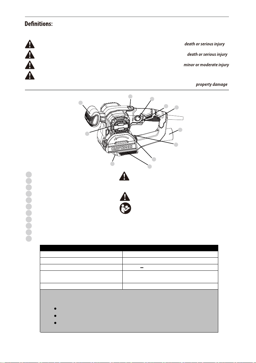
DANGER: Indicates a n imminently hazardous situation wh ich, if not avoided, will result in .
WARNING: Indicates a potentially hazardous situation w hich, if not avoided, could resul t in .
CAUTION: Indicates a potentially hazardous situation w hich, if not avoided, may result in .
(Used without word) Indicates a safety related message.
NOTICE: Indicates a practice not related to personal i njury which, if not avoided, may result in .
1
Variable speed control
2
Lock-on button
3
ON/OFF trigger switch
4
Main handle
5
Dust port
6
Roller end cover hasp
7
Roller end cover clamp
8
Roller end cover
9
Roller
10
Air vents
11
handle
Rating: 120 V, 60 Hz AC
Amperes: 4 A
Speed: 1,000 3,200 RPM (no load)
Sanding roller size: 2 13/16" (72mm) diameter
Weight: 4 lb. 8 oz. (2.0 kg)
Need Assistance?
Call our toll free customer support line:1-888-331-4569
1
11
10
9
Components
WARNING: Read all s afety warnings and all
instructions. Fail ure to follow the warnings and
instructions may re sult in electric shock, fire and/or
WARNING: Never mod ify the product or any part of it.
WARNING: To reduce the risk of injury, read the
If you have any questions or comments about this or
any product, call CRAFTSMAN toll free at:
1-888-331-4569.
PRODUCT SPECIFICATIONS
4" (100mm) wide
Technical questions
Replacement parts
Parts missing from package
3
2
3
4
5
6
7
8
Page 4

WARNING:
manual and follow all Safety Rules and Operating Instructions. The important
precautions, safeguards and instructions appearing in this manual are not
meant to cover all possible situations. It must be understood that common
sense and caution are factors which cannot be built into the product.
!
GENERAL SAFETY WARNINGS
Before using this tool or any of its accessories, read this
This instruction manual includes the following:
General Safety Rules
Specific Safety Rules and Symbols
Functional Description
Assembly
Operation
Maintenance
Accessories
EYE, EAR & LUNG PROTECTION
ALWAYS WEAR EYE PROTECTION THAT CONFORMS WITH CAN/CSA
STANDARD Z94.3 or ANSI SAFETY STANDARD Z87.1
FLYING DEBRIS can cause permanent eye damage. Prescription
eyeglasses ARE NOT a replacement for proper eye protection.
WARNING:
broken during the operation of a power tool.
!
WARNING: Use hearing protection, particularly during extended
periods of operation of the tool, or if the operation is noisy.
Non-compliant eyewear can cause serious injury if
!
SAVE THESE INSTRUCTIONS FOR REFERENCE
4
Page 5
GENERAL SAFETY WARNINGS
ELECTRICAL SAFETY
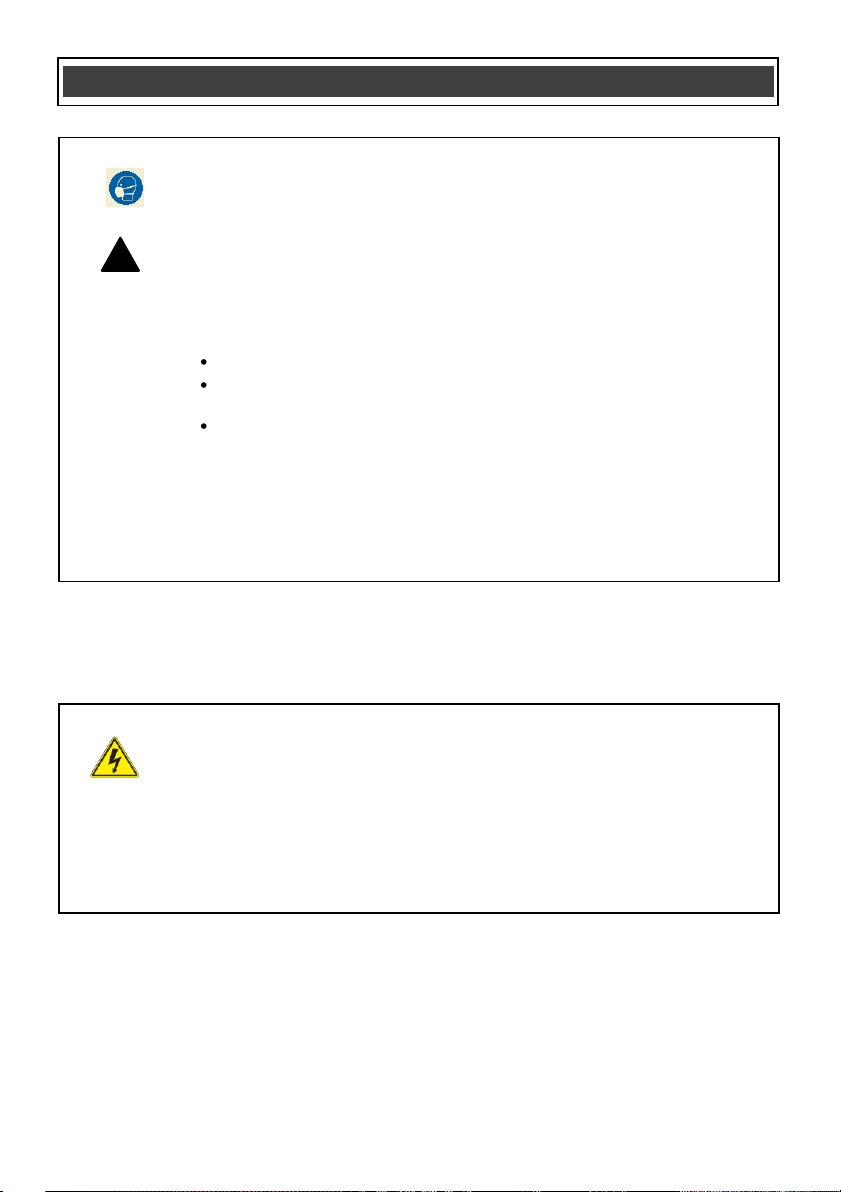
WEAR A DUST MASK THAT IS DESIGNED TO BE USED WHEN
OPERATING A POWER TOOL IN A DUSTY ENVIRONMENT.
WARNING:
!
drilling, and other construction activities may contain chemicals that are
known to cause cancer, birth defects, or other genetic abnormalities. These
chemicals include:
Lead from lead-based paints
Crystalline
products
Arsenic and chromium from chemically treated lumber
The level of risk from exposure to these chemicals varies, according to how
often this type of work is performed. In order to reduce exposure to these
chemicals, work in a well-ventilated area, and use approved safety
equipment, such as a dust mask that is specifically designed to filte
microscopic particles.
WARNING:
tool, use proper circuit protection.
This tool is wired at the factory for 120 V AC operation. It must be
connected to a 120 V AC, 15 A circuit that is protected by a time-delayed
fuse or circuit breaker. To avoid shock or fire, replace power cord
immediately if it is worn, cut or damaged in any way.
Dust that is created by power sanding, sawing, grinding,
silica from bricks, cement, and ot
To avoid electrical hazards, fire hazards or damage to the
her masonry
r out
SAVE THESE INSTRUCTIONS FOR REFERENCE
5
Page 6

follow the warnings and instructions may result
in electric shock, fire and/or serious injury.
Save all warnings and instructions for future
reference.
WORK AREA SAFETY
Keep work area clean and well lit. Cluttered or
dark areas invite accidents.
Do not operate power tools in explosive
atmospheres, such as in the presence of
flammable liquids, gases or dust. Power
create sparks which may ignite the dust or
fumes.
Keep children and bystanders away while
operating a power tool. Distractions can cause
you to lose control.
ELECTRICAL SAFETY
Power tool plugs must match the outlet.
Never modify the plug in any way. Do not
use any adapter plugs with earthed
(grounded) power tools. Unmodified plugs and
matching outlets will reduce risk of electric
shock.
Avoid body contact with earthed or
grounded
ranges and refrigerators. There is an
increased risk of electric shock if your body is
earthed or grounded.
Do not expose power tools to rain or wet
conditions. Water entering a power tool will
increase the risk of electric shock.
Do not abuse the cord. Never use the cord
for carrying, pulling or unplugging the power
tool. Keep the cord away from heat, oil,
sharp edges or moving parts. Damaged or
entangl
shock.
!
WARNING:
warnings and instructions. Failure to
surfaces such as pipes, radiators,
ed cords increase the risk of electric
POWER TOOL SAFETY
Read all safety
tools
SAVE THESE INSTRUCTIONS FOR REFERENCE
When operating a power tool outdoors, use
an extension cord suitable for outdoor use.
Use of a cord suitable for outdoor use reduces
the risk of electric shock.
If operating a power tool in a damp location
is unavoidable, use a residual current device
(RCD) protected supply. Use of a ground f ault
circuit interrupter (GFCI) reduces the risk of
electric shock.
PERSONAL SAFETY
Stay al
common sense when operating a power tool.
Do not use a power tool while you are tired
or under the influence of drugs, alcohol or
medication. A moment of inattention while
operating power tools may result in serious
personal injury.
Use personal protective equipment. Always
wear eye protection. Protective equipment
such as dust mask, non-skid safety shoes, hard
hat, or hearing protection used fo
conditions will reduce personal injuries.
Prevent unintentional starting. Ensure the
switch is in the off-position before
connecting to power source and/or battery
pack, picking up or carrying the tool.
Carrying power tools with your finger on the
switch or energizing power tools that have the
switch on invites accidents.
Remove any adjusting key or wrench before
turning the power tool on. A wrench or a key
left attach
may result in personal injury.
Do not overreach. Keep proper footing and
balance at all times. This enables better
control of the power tool in unexpected
situations.
Dress properly. Do not wear loose clothing
or jewelry. Keep your hair, clothing and
gloves away from moving parts. Loose
clothes, jewelry or long hair can be caught in
moving parts.
ert, watch what you are doing and use
r appropriate
ed to a rotating part of the power tool
6
Page 7

Personal safety
If devices are provided for the connection of
dust extraction and collection facilities,
ensure these are connected and properly
used. Use of dust collection can reduce dust-
related hazards.
POWER TOOL USE AND CARE
Do not force the power tool. Use the correct
power tool for your application. The correct
power tool will do the job better and safer at the
rate for which it wa
Do not use the power tool
not turn it on and off. Any power tool that
cannot be controlled with the switch is
dangerous and must be repaired.
Disconnect the plug from the power source
and/or the battery pack from the power tool
before making any adjustments, changing
accessories, or storing power tools. Such
preventive safety measures reduce the risk of
starting the
Store idle power tools out of the reach of
chi
with the power tool or these instructions to
operate the power tool. Power tools are
dangerous in the hands of untrained users.
Maintain power tools. Check for
misalignment or binding of moving parts,
breakage of parts and any other condition
that may affect the power tool’s operation. I
damaged, have the power tool repaired
before use. Many accidents are caused by
poorly maintained power tools.
Keep
maintained cutting tools with sharp cutting
edges are less likely to bind and are easier to
control.
ldren and do not allow persons unfamiliar
cutting tools sharp and clean. Properly
s designed.
power tool accidentally.
POWER TOOL SAFETY
if the switch does
Use the power tool, accessories and tool bits
etc. in accordance with these instructions,
taking into account the working conditions
and the
work to be performed. Use of the
power tool for operations different from those
intended could result in a hazardous situation.
Hold power tool by insulated grippi
surfaces, because the abrasive sleeve may
contact its own cord. Cutting a "live" wire may
make exposed metal parts of the tool "live" and
could give the operator an electric shock.
SERVICE
Have your power tool serviced by a qualifie
repair person using only identical
replacement parts. This will ensure that the
safety of the power tool is maintained.
f
ng
d
SAVE THESE INSTRUCTIONS FOR REFERENCE
7
Page 8

Do not plug in the Restorer
until you have read and understand this
Instruction Manual. Learn the tool’s
applications and limitations, as well as the
specific potential hazards related to this tool.
Following this rule will reduce the risk of electric
shock, fire, or serious injury.
Always wear eye protection. Any power
tool can throw foreign objects into your
eyes and cause permanent eye damage.
ALWAYS wear safety g
comply with CAN/CSA Standard Z94.3 or ANSI
safety standard Z87.1. Everyday glasses have
only impact resistant lenses. They ARE NOT
safety glasses.
!
WARNING: Glasses or goggles not in
compliance with ANSI Z87.1 could cause
serious inj
!
when sanding or stripping paint.
!
protection when using this tool, particularly
during extended periods of operation.
!
the power source before changing the roller,
sanding cylinder, accessory and when
cleaning the tool.
!
WARNING: FIRE HAZARD:
Never us
atmosphere or combustible materials. If the
sandpaper hits a nail or any ferrous metal, a
spark could cause an explosion of fire.
!
WARNING: FIRE HAZARD:
Collected sanding dust from sanding
coatings such as polyur
etc. can self-ignite. To reduce the risk, clear
dust frequently from the sanding drum area and
from the surrounding work area. Str
the cleaning instructions in the Owner’ s Manual
and coating manufacturer’s instructions.
ury when they break.
WARNING: Always use a dust mask
WARNING: Always use hearing
WARNING: Always unplug the tool from
e this tool near explosive
SPECIFIC SAFETY RULES
oggles (not glasses) that
ethane, linseed oil
ictly follow
!
WARNING:
and a dust mask when using compressed air
to remove sanding dust from the tool.
!
WARNING: Make sure the roller has
come to a full stop before taking your hands
off the tool. If the roller is still moving, the tool
may move erratically and either damag
workpiece or cause injury to the user.
Always place the Restorer on its “ nose”
(balanced between the front handle and the
roller housing) when the tool is turned OFF and
when storing the tool. This will prevent
inadvertent loss of control if the tool is
accidentally turned ON. It will also avoid the
roller from developi
stored for long periods of time with weight
the roller.
Always use two hands when operating the
Restorer. One hand should be used on the front
handle and the other hand should be placed on
the rear handle to operate the switches. Using
both hands will provide better control over the
tool.
Do not wear gloves, neckties or loose clothing.
Secure the workpiece. Use clamps or a vise to
hold the wo
using yo
ur hand and it frees both hands to
operate the tool.
Do not use this tool on material too small to be
securely held.
Make sure there are no nails or foreign objects
in the part of the workpiece to be sanded or
cleaned.
Always keep hands out of the path of the roller.
Avoid awkward hand positions where a sudden
slip could cause your hand to move into the path
of the roller.
Always use safety goggles
e the
ng a flat spot if the tool is
on
rk when practical. It is safer than
SAVE THESE INSTRUCTIONS FOR REFERENCE
8
Page 9

9
GUIDELINES FOR EXTENSION CORDS
!
(
(
(
(
!
Make sure your extension cord is the proper
size. When using an extension cord, be sure to
use one heavy enough to carry the current the
tool will draw. An undersized cord will cause a
drop in line voltage resulting in loss of power
and overheating. The table at right shows the
correct size to use according to cord length and
nameplate ampere rating. If in doubt, use the
next heavier gauge. The sma
number the heavier
the cord.
ller the gauge
Be sure your extension cord is properly
wired and in good condition. Always replace a
damaged extension cord or have it repaired by a
qualified electrician before using it. Protect your
extension cord from sharp objects, excessive
heat and damp or wet areas.
Use a separate electrical circuit for your
power tools. This circuit must not be less than
14 ga
uge wire and should be protected with
either a 15A time delay fuse
or circuit breaker.
Before connecting the power tool to the power
source, make sure the switch is in the OFF
position and the power source is the same as
indicated on the nameplate. Running at lower
voltage will damage the motor.
WARNING: Repair or replace damaged
or worn extension cords immediately.
Select the appropriate exte
nsion cord gauge
and length using the chart at right.
When operating a power tool outdoors, u
se
an outdoor extension cord marked “W -A” or
hese cords are rated for outdoor use and
T
“W”.
reduce the risk of electric shock.
WARNING: Keep the extension cord
clear of the working area. Position the cord
so it will not get caught on the workpiece,
tools or any other obstructions while you are
working with the power tool.
MINIMUM GAUGE (AWG) EXTENSION
CORDS (120 V use only)
Ampere rating Total length in feet
More
than
Not
more
than
0 6 18 16 16 14
6 10 18 16 14 12
10 12 16 16 14 12
12 16 14 12 Not Applicable
7.5 m
25')
15 m
50')
30 m
100')
45 m
150')
SAVE THESE INSTRUCTIONS FOR REFERENCE
Page 10

This symbol designates that this tool Conforms
t
t
b
3042597
V
A
Hz
W
kW
L
kg
H
Newtons per square
centimeter
Pa
OPM
Min
S
Three-phase alternating
current
Three-phase alternating
current with neutral
Alternating or direct
current
Splash-proof
construction
Protective grounding at
Class I tools
Revolutions or
minute
Wear your safety
glasses
SYMBOLS
WARNING:
!
these symbols and learn their meaning. Proper interpretation of these symbols will
allow for more efficient and safer operation of this tool.
Some of the following symbols may appear on the Restorer. Study
Volts
Amperes
Hertz
Watts
Kilowatts
Microfarads
Liters
Kilograms
Hours
N/cm2
Pascals
Oscillations per minute
Minutes
Seconds
or a.c.
Alternating current
Direct current
JD2679U
o UL Std. 60745-1, 60745-2-4 and is Certified
o CAN/CSA Std.C22.2 No. 60745-1, 60745-2-4
y ETL Testing Laboratories, Inc.
No load speed
Class II construction
Watertight construction
grounding terminal,
reciprocations per
Diameter
Off position
Directional arrow
Warning symbol
Wear a dust mask
Wear hearing protection
Fire hazard
Read all instructions
Page 11

CHANGING SANDING SLEEVE ON ROLLER
!
WARNING: Remove the plug from the
power source before installing or removing a
sanding roller.
1. Lift the two roller end cover hasps (1) away
from the main housing (2) (Fig. 1).
2
1
3
2. Release the RIGHT hasp from the roller
end cover (3).
3. Pull the cover out from the main housing
and flip it toward the front of the tool using
the LEFT hasp as a hinge (Fig
ASSEMBLY AND OPERATING
1
Fig. 1
2).
4. Slide the roller (4) off the roller shaft (5).
5. Remove the old sanding sleeve and slide
the new sanding sleeve (6) onto the roller
(4) (Fig. 3).
NOTE: Rotate the roller sleeve counterclockwise as you slide the roller sleeve fully
onto the roller. Make sure it is centered on
the roller and is not overhanging one end
of the roller.
Fig. 2
6. Slide the roller onto the roller shaft
NOTE: The roller can only be installed one
. When properly installed, the
way
directional arrow (7) on the end of the roller
will be visible.
7. Reinstall the roller end cover and fasten it
in place with the two roller end cover
hasps.
CAUTION: Make sure the roller end cover
is properly seated onto the main housing
and the hasps snap into place.
VARIABLE SPEED CONTROL
The variable sp
change the speed at which the roller will rotate
(Fig. 5). Rotate the speed c ontrol to the LEFT
(#1) for slowest speed and to the right (MAX) for
the fastest speed.
NOTE: See "SANDING" section of this manual
for recommended speeds.
Fig. 3
Fig. 4
eed control (1) can be rotated to
11
6
4
7
(Fig. 4).
Page 12

ON/OFF TRIGGER SWITCH
The ON/OFF trigger switch (1) is a single
function switch (Fig. 6). To turn the tool ON,
squeeze the trigger. To turn the tool OFF,
release the trigger.
LOCK-ON BUTTON
The lock-on button (2) is used to lock the
ON/OFF trigger switch in the ON position
(Fig. 7). Locking the trigger switch in the ON
position will reduce hand fatigue when operating
the tool for extended perio
1. To lock the trigger switch i
position, squeeze the trigger (1) to turn the
tool ON.
2. While squeezing the trigger, press the lockon button (2) into the handle.
3. While holding the lock-on button into the
handle, release the trigger. At this point,
the tool will remain running.
ASSEMBLY AND OPERATING
1
Fig. 5
Fig.
1
6
ds of time.
n the ON
4. To release the lock-on button to turn the
tool OFF, squeeze and then release the
trigg
er. The trigger switch will then turn
OFF.
!
WARNING:
depressed by cycling the ON/OFF switch
several times or by depressing and releasing
the switch several times before plugging in your
restorer. Damage to your tool or personal injury
may result.
!
WARNING
Fig. 7
Be sure the lock button is not
2
1
12
Page 13

13
ASSEMBLY AND OPERATING
!
!
! ! !
SANDING
This tool can be used to sand rough material or
to remove paint, varnish or other finishes.
WARNING: Always use safety glasses,
dust mask and hearing protection when
operating this tool. Failure to wear these
protective devices may cause serious
injuries.
WARNING: Never use this tool near
flammable materials. A spark from sanding
hidden fasteners could ignite flammable
rials.
mate
WARNING: An unsecured workpiece
could be thrown toward the operator causing
injury.
WARNING: Clamp or otherwise secure
your workpiece to prevent it from moving under
the Restorer while being sanded.
WARNING: Always use two hands to
operate this tool. One hand should be on the
front handle and the other on the rear
handle. Failure to use two hands may cause
the tool to be
cause serious injury to the operator.
Do NOT cover the cooli
will cause the tool to overheat and damage the
tool.
Before starting any sanding project, you should
practice sanding on a scrap workpiece similar to
the item to be sanded. This will allow you to get
the "feel" of the tool and also establish the grit of
the sanding sleeve and
the type of material being sanded.
In general, removing heavier finishes and when
sanding rough surface
sleeve and slower tool speeds are
recommended. Slower speeds will reduce the
heat created while sanding and reduce the
tendency of the sanding sleeve to become
clogged. For sanding smoother surfaces without
finishes, finer sanding sleeves and higher
speeds are recommended.
difficult to control and possibly
ng vents in the tool. This
tool speed to best suit
s, a coarser sanding
tool
To begin sanding, install the appropriate
sanding sleeve, set the tool speed and squeeze
the trigger switch to turn the tool ON.
NOTE: The sa
contact with the workpiece until it has reached
its operating speed.
Once the tool has reached its operating speed,
hold onto the tool with both hands and carefully
bring the sanding sleeve into
workpiece.
NOTE: When the sanding sleeve contacts the
workpiece, the tool will tend to be pulled forward
away from you. Make sure you have a firm grip
on the tool with both hands.
NOT FORCE THE RESTORER. The weight
DO
of the Restorer usually provides adequate
pressure. Let the Restorer and the sandpaper
do the work. Applying added pressure will slow
the motor, increase the wear on t
sleeve and greatly reduce the tool speed. Motor
damage may occur if excessive downward
pressure is applied. It will also create an inferior
finish on sanded work. Any finish or resin on
wood will soften from the frictional heat, c
the sanding sleeve to become clogged very
quickly. Do not sand in one spot as the sanding
sleeve will remove too much material, making
the surface uneven.
When sanding wood, always move the Restorer
forward and backward with the grain (Fig. 8).
Sanding across the grain will not leave a smooth
surface.
nding sleeve should NOT be in
contact with the
he sanding
ausing
Fig. 8
Page 14

SANDING
Always keep the tool "moving" when the sanding
sleeve is in contact with the workpiece. This is
particularly important when sanding wood or
other soft materials. Failure to keep the tool
"moving" will result in gouges in the workpiece.
Do not allow sanding dust to accumulate in the
tool. Stop and clean out all loose sanding dust
at regular intervals to prevent unnecessary
buildup that
and to guard against overheating. Refer to
"CLEANING THE TOOL" f or details.
Always place the Restorer on its “nose”
(balanced between the front handle and the
roller housing) when the tool is turned OFF and
when storing the tool (Fig. 9). This will prevent
inadvertent loss of control if the tool is
accidentally turned ON. It will also prevent the
roller from developing a flat spot if the tool is
stored for long periods of time w
will cause the tool to be ineffi
ASSEMBLY AND OPERATING
cient
ith weight on
Fig. 9
CLEANING THE TOOL
It is important to keep the tool as clean as
possible to reduce the risk of fire and to produc e
the best possible sanding results.
!
WARNING: Always remove the plug
from the power source before removing the
sanding roller and before cleaning the tool.
!
WARNING: Always wear safety goggles
and a dust mask when using compressed air
to remove sanding dust from the tool.
!
WARNING:
brake fluids, gasoline, petroleum-based
products, penetrating oils, etc. to come in
contact with plastic parts. They contain
chemicals that can damage, weaken or
destroy plastic.
1. Unlatch the roller end cover (Fig. 1).
2. Remove the roller from the tool.
3. Remove the
4. Use compressed air to blow all the loose
sanding dust from the:
NOTE: If compressed air is not available, use a
soft DRY long bristled brush to remove the
sanding dust.
Use a clean, dry cloth to remove sanding dust
from the other tool components.
NOTE: Do NOT use any solvents or water on
the cloth.
Do not at any time allow
sanding sleeve from the roller.
roller housing,
roller end cover.
slots in the roller, and
dust chute in the back of the rear
handle.
14
Page 15

15
MAINTENANCE
!
! ! !
GENERAL
WARNING: When servicing, use only
identical replacement parts. Use of any other
replacement parts may create a hazard or
cause product damage.
DO NOT use solvents when cleaning plastic
parts. Most plastics are susceptible to damage
from various types of commercial solvents and
may be damaged by their use. Use a clean cloth
to remove dirt, dust, oil, grease, etc.
WARNING: Do not at any time allow
brake fluids, gasoline, petroleum-based
products, penetrating oils, etc. to come in
contact with plastic parts. They contain
chemicals that can damage, weaken or
destroy plastic.
DO NOT abuse power tools. Abusive practices
can damage the tool as well as the workpiece.
WARNING: DO NOT attempt to modify
tools or create accessories not
recommended. Any such alteration or
modification is misuse and could result in a
hazardous condition leading to possible
serious injury. It will also void the warranty.
It has been found that electric tools are
subjected to accelerated wear and possible
premature failure when they are used on
fiberglass boats and automotive parts,
wallboard, spackling compounds or plaster. The
chips and grindings from these materials are
highly abrasive to electric tool parts such as
bearings, brushes, commutators, etc.
Consequently, it is not recommended that this
tool be used for extended work on any
fiberglass material, wallboard, spackling
compounds or plaster. During any use on these
materials it is extremely important that the tool is
cleaned frequently by blowing the dust out of the
tool with an air jet. See "CLEANING THE TOOL"
section of this manual for details.
WARNING: Always wear safety goggles
or safety glasses with side shields during all
sanding operations. It is critical that you also
wear safety goggles or safety glasses with
side shields and a dust mask while blowing
dust out of the Restorer with an air jet.
Failure to take these safety precautions
could result in permanent eye or lung
damage.
LUBRICATION
All of the bearings in this restorer are lubricated
with a sufficient amount of high grade lubricant
for the life of the unit under normal conditions.
Therefore, no further lubrication is required.
Page 16

EXPLODED VIEW
16
Page 17

17
Key #
Part #
Part Name
Quantity
1
2
3
4
5
6
7
8
9
10
11
12
13
14
15
16
17
18
19
20
21
22
23
24
25
26
27
28
29
30
31
32
33
PARTS LIST
!
!
WARNING:
other parts may create a safety hazard or cause damage to the Restorer.
WARNING: To assure SAFETY and RELIABILITY of repairs, maintenance and accessories, the
use of any accessory not recommended for use with this tool could be hazardous. Recommended
accessories for use with your tool are available
you need assistance regarding accessories, please call the toll-free helpline at 1-888-331-4569.
Any attempt to repair or replace electrical parts on this Restorer may create a safety hazard unless
repairs are performed by a qualified technician. For more information, call the toll-free helpline, at
1-888-331-4569.
Always order by PART NUMBER, not by key number.
When servicing, use only original equipment replacement parts. The use of any
from your local dealer or authorized service center. If
1190030064
3140010054
4030010099
2030050002
1061260011
1130010270
3011300003
4030010106
3140070029
3150010116
1010310001
2040080048
2040040116
3160090120
4030010096
4010010054
2040080049
2030170007
4010010084
2040310051
2040040117
4130010020
6300010003
2030160168
4020010031
2040310052
4100020010
4030010179
2030020269
2030030316
3160090121
4010010042
3150050097
Cord & Plug
Cord Sleeve
Tapping Screw ST3.9X14
Strain Relief
Switch
Circuit board
Housing
Tapping Screw ST3.9X19
Non-slip mat
Fan
Rotor
Transmission gear
Gear shaft
Gear cover
Tapping Screw ST3.9X12
Bearing6000 2RS
Output gear
Bearing Washer
Bearing6002 2RS
Wheel coupling sleeve
Output shaft
Elastic
cylindrical pin
Roller
Anti-reverse platen
Tapping Screw M3X10
Quick coupling sleeve
Spring washer Φ14
Tapping Screw ST3.9X10
Bearing Washer
Sand ring baffle
Rear cover
Bearing696
Guide vane
1
1
2
1
1
1
1
12
2
1
1
1
1
1
5
2
1
1
2
1
1
1
1
1
2
2
1
8
2
2
1
2
1
Page 18

18
PARTS LIST
Key #
Part #
Part Name
Quantity
34
35
36
37
38
39
40
41
42
1020310001
4010010053
4030010120
2030030281
4030010020
1230010146
2030070053
3160050013
1250010002
Stator
Bearing607 2RS
Tapping Screw ST3.9X60
Hasp
Tapping Screw ST2.9X6
Carbon Brush
Brush Holder
Motor cover
Terminal block
1
1
2
2
4
2
2
1
1
CRAFTSMAN will repair, without charge, any defects due to faulty materials or
workmanship for three years from the date of purchase. This warranty does not
cover part failure due to normal wear or tool abuse. For further detail of warranty
THREE YEAR LIMITED WARRANTY
coverage and warranty repair information, visit www.craftsman.com
or call 1-888-331-4569. This warranty does not apply to accessories or damage
caused where repairs have been mad
e or attempted by others. This warranty
gives you specific legal rights and you may have other rights which vary in
certain states or provinces.
In addition to the warranty, CRAFTSMAN tools are covered by our:
1 YEAR FREE SERVICE: CRAFTSMAN will maintain the tool and replace worn
parts caused by normal use, for free, any time during the first year after
purchase.
90 DAY MONEY BACK GUARANTEE: If you are not completely satisfied with
the performan
ce of your CRAFTSMAN Power Tool, Laser, or Nailer for any
reason, you can return it within 90 days from the date of purchase with a receipt
for a full refund – no questions asked.
To register your tool for warranty service, visit our website at
www.craftsman.com.
LATIN AMERICA: This warranty does not apply to products sold in Latin
America. For products sold in Latin America, see country specific warranty
informa
tion contained in the packaging, call the local company or see website for
warranty information.
CRAFTSMAN
®
is a registered trademark of Stanley Black & Decker, Inc., used under license.
©2019 CRAFTSMAN.
Product Manufactured by: Jinding Group Co.,Ltd.
LICENSEE NAME: Wellington Corp LLC.
LICENSEE ADDRESS: 1510 Ridge Rd Vienna, OH 44473.
U.S. & Canada Only.
Rev 1.0 04/03/2019
 Loading...