

Page 1

Not for
Reproduction
Setup Guide
WARNING
AVOID SERIOUS INJURY OR DEATH:
Read and follow the tractor operator
manual bef
ore running engine.
ZTS 7000
Zero-Turn with Electric Start
Model Numbers:
C950-60106-0
C950-60106-1
C950-60107-0
C950-60107-1
Attention Setup Personnel:
The safety warnings provided in this guide and
in the tractor's operator manual included with
the unit contain important information that must
be followed when assembling, setting-up, operating,
servicing, transporting, or storing the unit.
These warnings are highlighted by the safety alert
triangle symbol shown above, which signifi es that an
important safety message is being provided.
You must read, understand, and follow these
warnings and instructions, and use safe shop
and work practices at all times while working on
or around this unit and all other outdoor power
equipment.
English Français
en
fr
Tools
EYE PROTECTION
WORK GLOVES
WRENCHES
7/16˝,1/2˝, 9/16˝, 3/4˝
TORQUE WRENCH
TIRE PRESSURE GAUGE
CLOTH (checking oil)
MEASURING TOOL FOR LEVELING
MOWER (4 inch stiff cardboard)
CUTTING TOOL FOR TIE DOWNS
7104985 Revision: B
lb-ft
( Nm)
Page 2
Not for
Reproduction
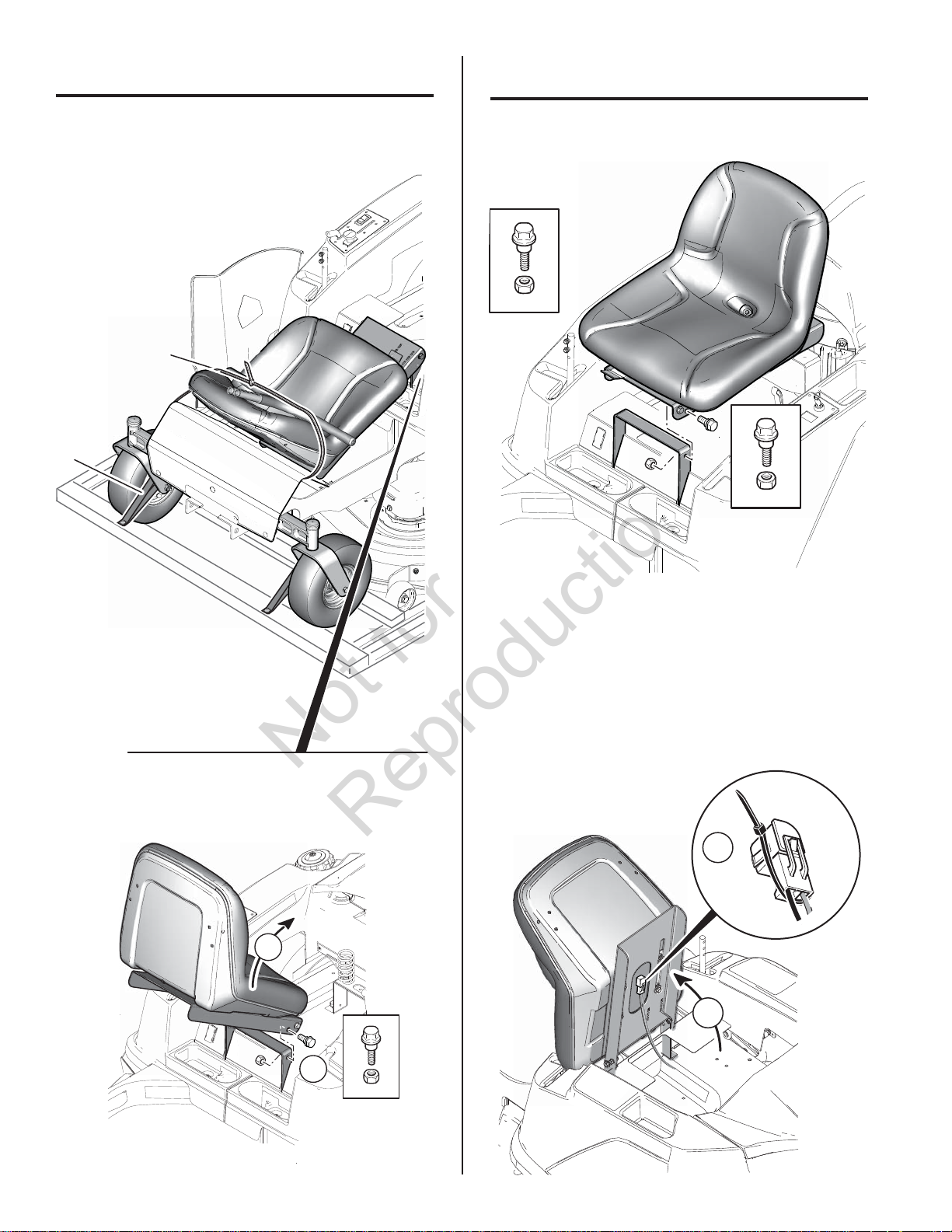
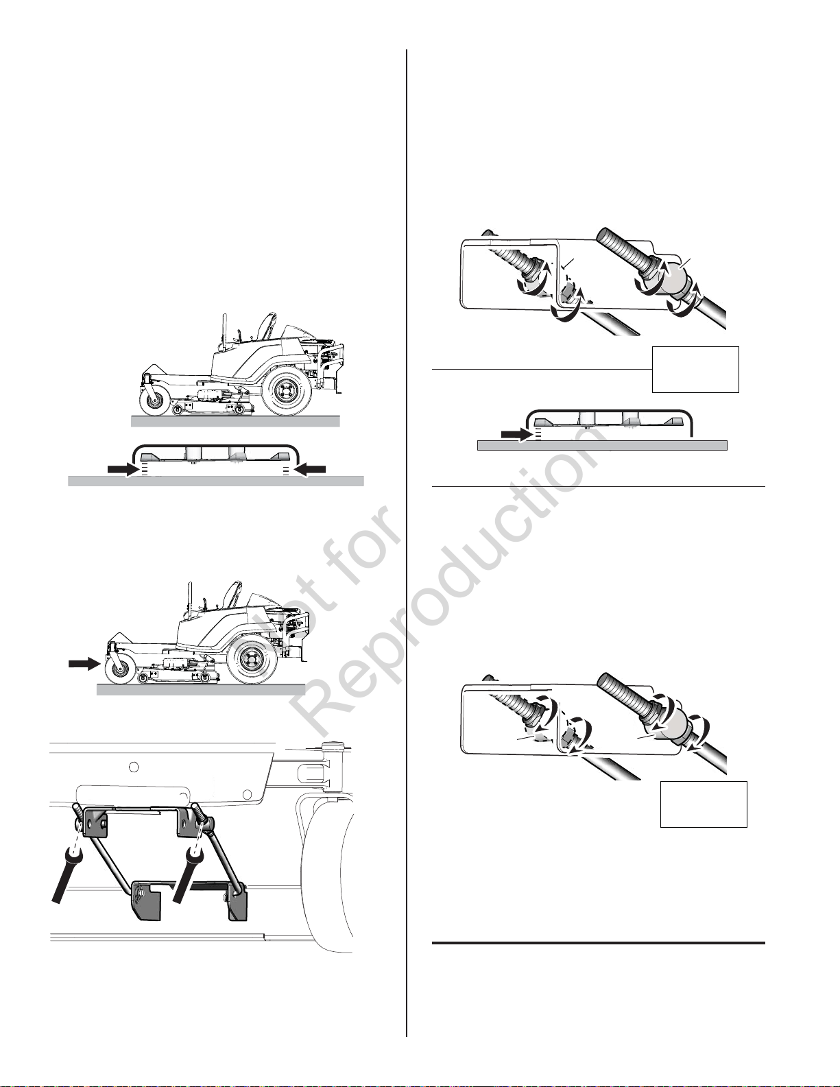
Disassemble
13 lb-ft
(18 Nm)
Note: Remove all ties (a) especially the ones holding
the unit onto the pallet.
a
a
Assembly
SEAT
Note: Remove bolts holding seat in shipping position.
1
2
SEAT SAFETY SWITCH
Note: Fasten seat switch harness to switch. Then
fasten tie as shown ( zip tie is in literature pack).
2
1
2
Page 3
Not for
Reproduction
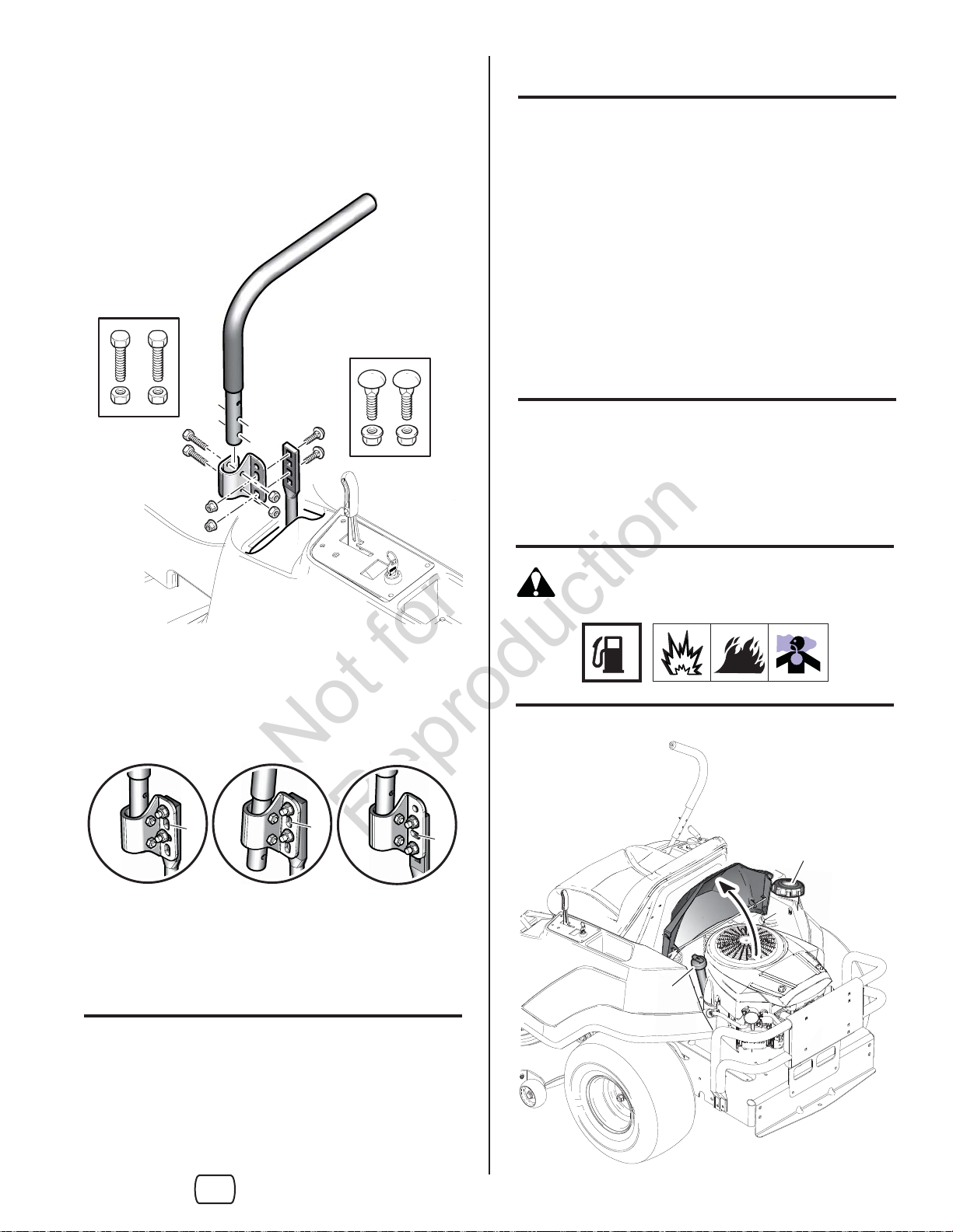
Check Oil Level (a)
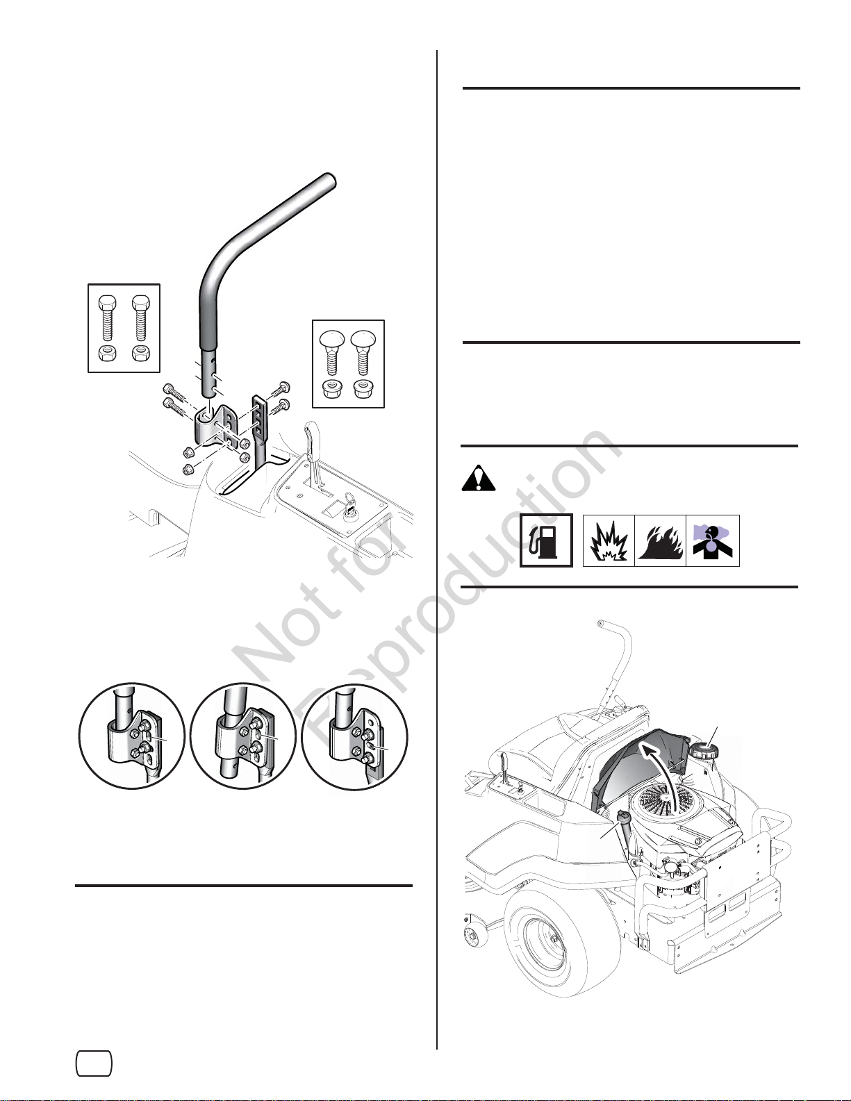
GROUND SPEED CONTROL LEVERS
13 lb-ft
(18 Nm)
13 lb-ft
(18 Nm)
Note: Engine is shipped with oil, however, oil should be
checked prior to use.
• Tractor should be on a level surface.
• Check that the engine is fi lled to full mark on
dipstick.
• See Operator's Manual for complete instructions.
and oil recommendations.
Fuel (b)
Fill the fuel tank with fresh gasoline. See Engine
Operator's Manual for complete instructions. and
gasoline recommendations. .
WARNING
LEVER HEIGHT AND ANGLE OPTIONS
Note: The bolts need to be spaced so there is a hole
open (a) in between.
a
a
Check Tire Pressure
Tires are over-infl ated for shipping purposes.
The maximum inflation is stamped on the sidewall of
the tires. Do not exceed the maximum tire pressure.
b
a
a
en
3
Page 4
Not for
Reproduction
a
a
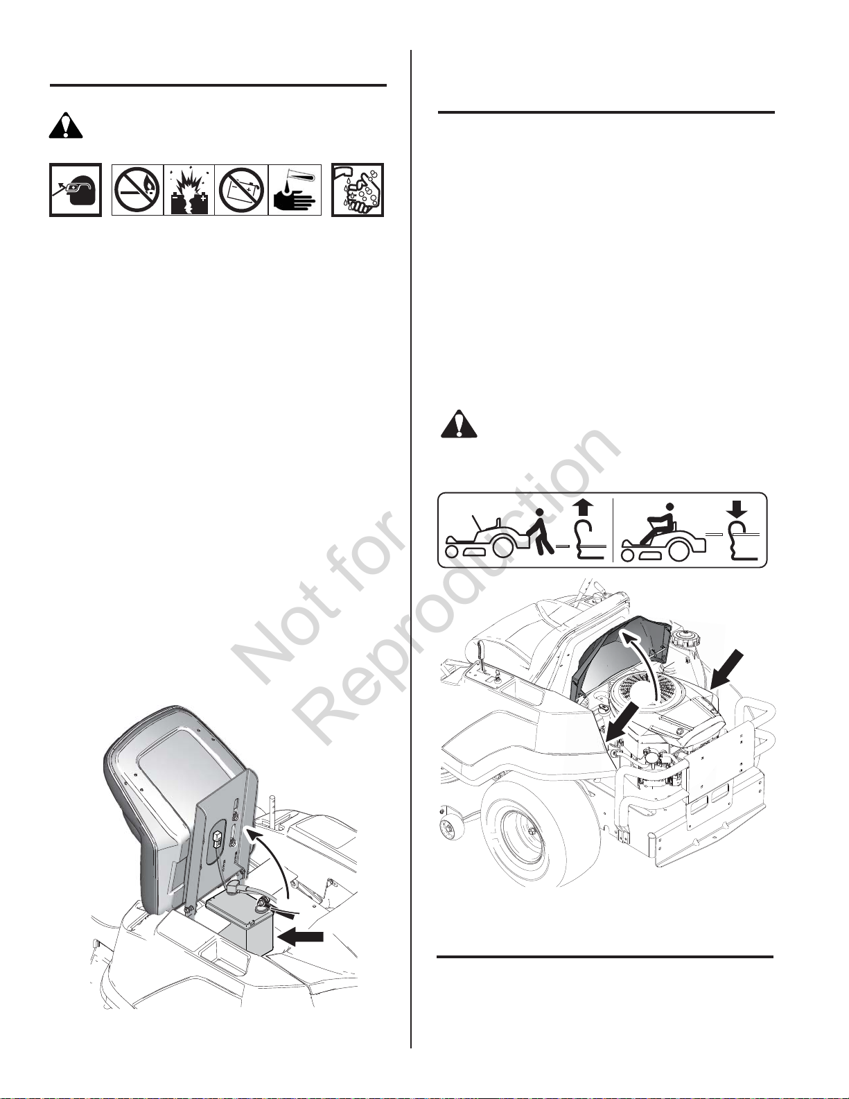
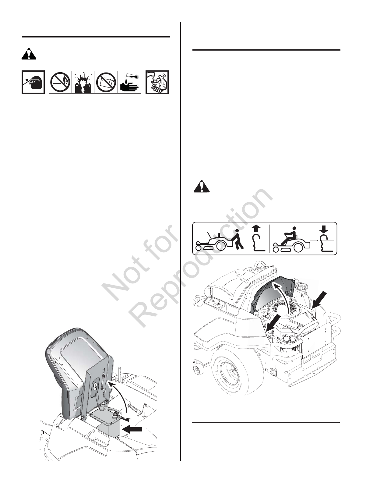
Charge Battery
Removing Tractor from Shipping
Pallet
WARNING
RISK OF BATTERY EXPLOSION FROM HYDROGEN
GAS MAY RESULT IN SERIOUS INJURY OR DEATH.
• ALWAYS wear safety glasses for your protection
while handling the battery.
• To avoid an explosion, keep fl ames and sparks
away from the battery, especially while charging.
• Battery acid causes severe burns. Avoid contact
with skin.
• Battery posts, terminals, and related accessories
contain lead and lead compounds - chemicals
known to the State of California to cause cancer
and reproductive harm. Wash hands after handling.
Note: If the unit is being put into service after the
month and year indicated on the battery date tag
(located on top of battery) charge the battery before
use.
See Operator's Manual for starting, stopping, and
operating information before driving tractor off shipping
pallet.
Important: When driving tractor off shipping pallet
raise the mower deck height to its highest cutting
position.
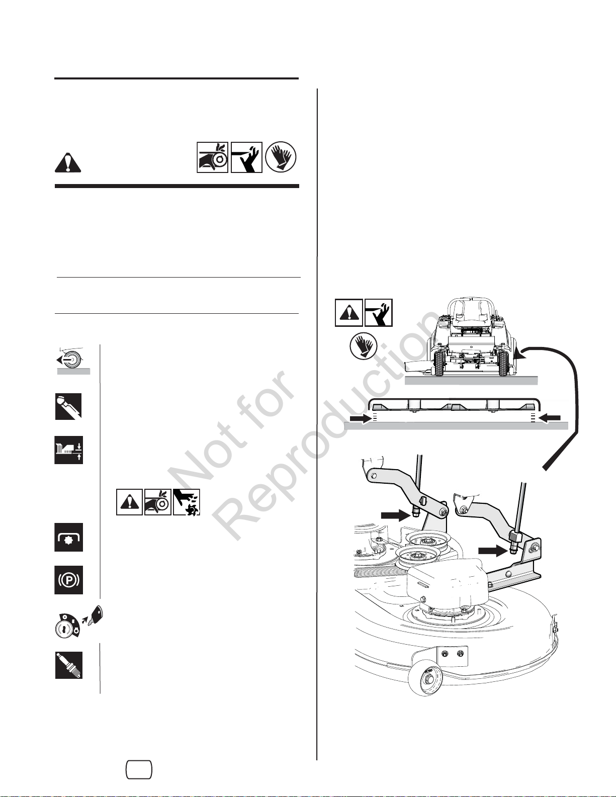
Check ROLL RELEAS S
Note: The roll (transmission) release levers (a) may
come from the factory in the RELEASE position.
The tractor will not drive if leavers are in the release
position.
WARNING
DO NOT use roll release unless engine is OFF.
Note: Charge battery according to the instructions
provided by the charger manufacturer.
Note: Read and understand any warnings by the
battery manufacturer.
Adjustment
4
The ground speed levers must be adjusted prior to use.
Refer to the "Ground Speed Lever Adjustment" section
in the Operator's
Page 5
Not for
Reproduction
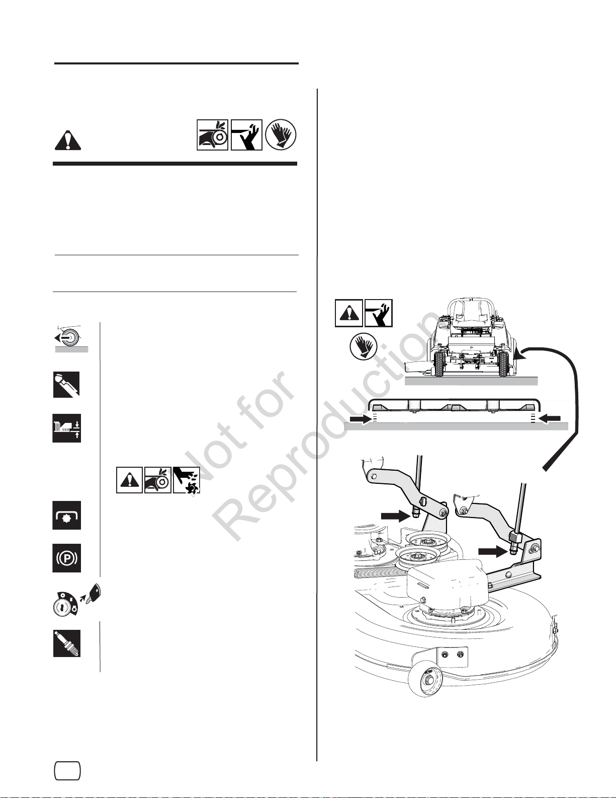
Mower Leveling
PREPARATION
WARNING
For your personal safety, do not handle the sharp
mower blades with bare hands. Careless or
improper handling of blades may result in serious
injury.
See Operator's Manual for complete control panel
instructions.
Park tractor on a hard level surface and
turn wheels straight.
Check tires for the correct pressures.
SIDE-to-SIDE LEVELING
Arrange the blades so they are pointing from side-toside. Using a measuring tool, measure the distance
between the the ground and the outside tips (a, b) of
each blade.
The diff erence should be: less than 1/8˝ (3mm).
IF AN ADJUSTMENT IS NEEDED:
Tighten / loosen nuts (c) (right and left side) as needed
to adjust side-to-side leveling.
Place mower approximately in the middle
height of cut position.
Disengage mower blades.
Set parking brake.
Turn ignition OFF and remove key.
Disconnect spark plug wires and place
away from plugs.wheels straight.
a
b
c
c
en
5
Page 6
Not for
Reproduction
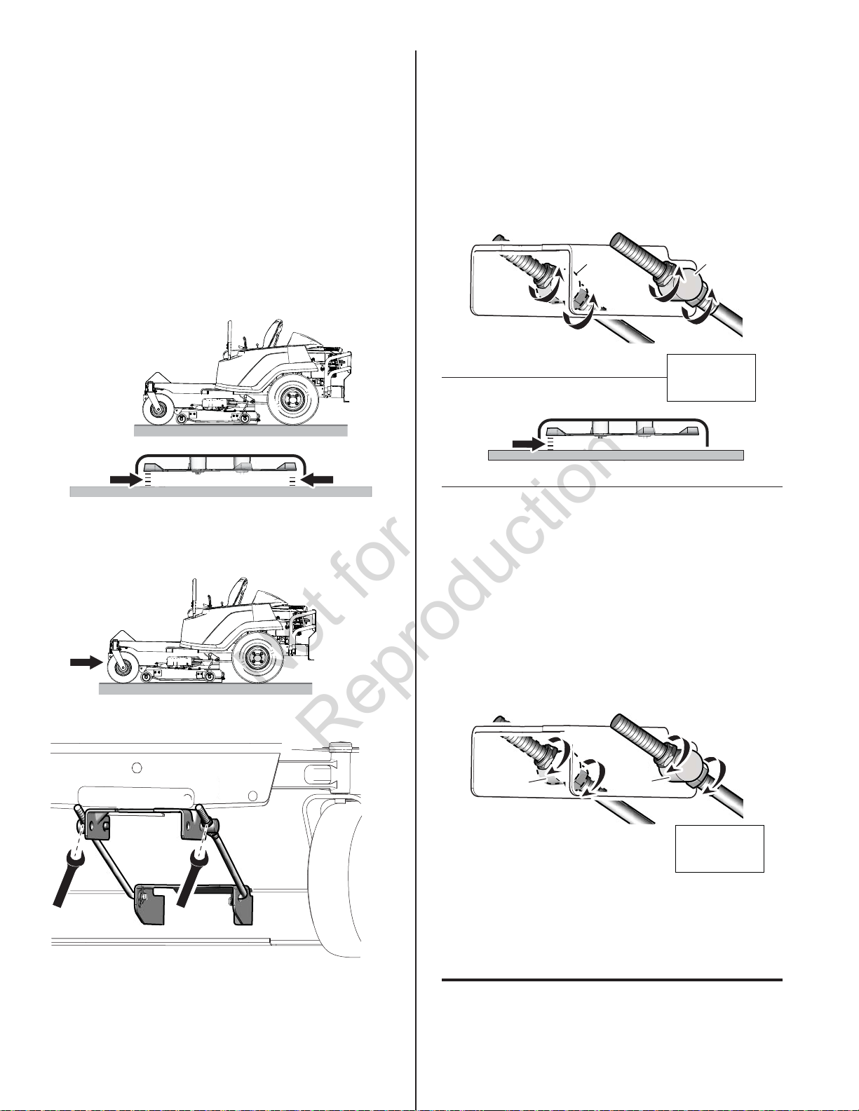
FRONT-to-BACK LEVELING
1/2
To LOWER the front of mower (b).
Important: Side-to-side leveling must be
performed fi rst.
Arrange the blades so it faces front to back. Using a
measuring tool, measure:
(a) - the distance between the ground and the
rear tip of one of the rear blades.
(b) - the distance between the ground and front
tip of the center blade.
This should be the same as measurement (a).
ab
Turn locknuts (c) counterclockwise. Locknuts
must be turned evenly on both sides to keep deck
level (Side-to Side).
Recheck measurement (b). When correct, turn jam
nuts (d) counterclockwise against the trunnion (e),
to secure.
e
c
c
d
e
d
90 lb-ft
(122.4 Nm)
b
IF AN ADJUSTMENT IS NEEDED:
1/2
1/2
1/2
To RAISE front of mower (b).
Turn jam nuts (c) clockwise. Nuts must be turned
evenly on both sides to keep deck level (Side-to-
Side). Turn locknuts (d) clockwise against the
trunnion (e) to secure.
Recheck measurement (b).
d
c
90 lb-ft
(122.4 Nm)
e
d
c
e
For answers to your questions about
this product, call:
6
1-800-659-5917
Sears Craftsman Help Line
5 am - 5 pm, Mon - Sat
Page 7
Not for
Reproduction
ZTS 7000
Braquage zéro avec démarrage électrique
Guide de montage
AVERTISSEMENT
ÉVITER DE SÉRIEUSES BLESSURES,
VOIRE LA MORT :
Lisez et suivez le manuel d’utilisation
du tracteur avant de faire fonctionner le
moteur.
Outils
Nombres Modèles:
C950-60106-0
C950-60106-1
C950-60107-0
C950-60107-1
Mise en garde à destination des
personnes chargées du montage:
Les avertissements de sécurité fournis dans ce
guide et dans le manuel d’utilisation du tracteur
inclus dans la machine contiennent
des informations importantes qui doivent à suivre
lors de l’assemblage, du montage, de l’utilisation, de
l’entretien, du transport ou du remisage de la machine.
Ces avertissements sont mis en évidence par le
symbole d’alerte de sécurité dans un triangle illustré
ci-dessus, ce qui signifi e qu’un message de sécurité
important est fourni.
Vous devez lire, comprendre et suivre ces
avertissements et ces instructions et observer en
permanence à des pratiques de travail en atelier
sûres quand vous travaillez sur ou autour de cette
machine et de tout autre équipement électrique
pour l’extérieur.
English
en
Français
fr
PROTECTION DES YEUX
GANTS DE TRAVAIL
CLÉS
7/16˝,1/2˝, 9/16˝, 3/4˝
CLÉ DYNAMOMÉTRIQUE
JAUGE DE PRESSION DES PNEUS
CHIFFON (pour vérifier l’huile)
INSTRUMENT DE MESURE POUR
MISE À NIVEAU DU PLATEAU DE
COUPE (caisse rigide de 4 pouces)
OUTIL DE COUPE POUR
ARRIMAGE
7104985 Révision: B
lb-ft
( Nm)
Page 8

Not for
Reproduction
Remarque : Retirez tous les liens et spécialement
13 lb-ft
(18 Nm)
ceux retenant la machine sur la palette.
a
a
MontageDémonter
SIÈGE
Remarque : retirer les boulons qui retiennent le siège
en position de transport.
1
2
COMMUTATEUR DE SÉCURITÉ DU SIÈGE
Attachez le faisceau (a) du commutateur du siège
au commutateur (b). Puis serrez bien (c) comme
illustré (l’attache mono-usage est dans le sac de
documentation).
b
2
c
1
a
2
Page 9
Not for
Reproduction
LEVIERS DE COMMANDE DE LA VITESSE
Vérifi ez le niveau d’huile (a)
Remarque : Le moteur est livré avec de l'huile, mais
l'huile doit être vérifi ée avant utilisation.
• Stationnez le tracteur sur une surface plane.
• Vérifi ez le niveau d’huile sur la jauge comme
illustré ci-dessous. Ajoutez de l’huile si le niveau
est sous la marque supérieure.
13 lb-ft
(18 Nm)
13 lb-ft
(18 Nm)
OPTIONS DE HAUTEUR ET D'ANGLE DU LEVIER
Remarque : les boulons doivent être espacés de
manière qu’il y ait un trou de libre (a) entre eux.
• Voir le manuel d’utilisation pour des instructions
complètes.
Fuel (b)
Remplir le réservoir d'essence avec de l'essence
neuve. Vous reporter au manuel d'instruction du
moteur pour les directives complètes ainsi que les
recommandations pour l'essence. .
AVERTISSEMENT
a
a
Vérifi cation de la pression des pneus
Les pneus sont surgonfl és pour faciliter
l’expédition.
Le gonflage maximal est marqué sur le flanc des
pneus. Ne pas dépasser la pression maximale.
fr
a
b
a
3
Page 10
Not for
Reproduction
a
a
Charger/connecter la batterie
Retirer le tracteur de la palette de
transport
AVERTISSEMENT
RISQUE D’EXPLOSION DE BATTERIE CAUSÉE
PAR L’HYDROGÈNE ET POUVANT PROVOQUER DE
GRAVES BLESSURES, VOIRE LA MORT.
• Portez TOUJOURS des lunettes de protection pour
vous protéger les yeux quand vous manipulez la
batterie.
• Pour éviter toute explosion, faites en sorte qu’il ne
se produise ni fl ammes ni étincelles à proximité de
la batterie, spécialement pendant qu’elle se charge.
• L’acide de la batterie provoque de graves brûlures.
Évitez tout contact avec la peau.
• Les bornes, les plots et autres accessoires de la
batterie contiennent du plomb et des composés
de plomb – des produits chimiques reconnus par
l’État de Californie comme étant cause de cancer
et d’anomalies congénitales. Se nettoyer les mains
après la manipulation.
Vous reporter au manuel de l'opérateur pour
des informations sur le démarrage, l'arrêt et le
fonctionnement avant de descendre le tracteur de la
palette de transport.
Important : Lorsqu'on descend le tracteur d'une
palette de transport, lever la hauteur du plateau de la
tondeuse à sa plus haute position de coupe.
Vérifi er - LEVIERS DE DÉGAGEMENT DE
ROULEMENT
Remarque : Les leviers de dégagement de roulement
(transmission) (a) peuvent être livrés d'usine dans la
position RELEASE (dégagée). Le tracteur ne pourra
pas rouler si les leviers sont dans cette position.
AVERTISSEMENT
NE PAS utiliser le dégagement de roulement à
moins que le moteur ne soit éteint.
Remarque : Si la machine est mise en service
après le mois et l’année indiqués sur l’étiquette de
date de la batterie (située sur la partie supérieure
de la batterie), chargez la batterie avant utilisation.
Remarque: Chargez la batterie en vous conformant
aux instructions fournies par le fabricant du chargeur.
Remarque : Lisez et comprenez tous les
avertissements du fabricant de la batterie.
Réglages
4
Le réglage des leviers de commande de vitesse
doit être eff ectué avant la première utilisation. Vous
reporter à la section « Réglage du leviers de vitesse de
déplacement » dans le manuel de l'opérateur
Page 11
Not for
Reproduction
Mise à niveau du plateau de coupe
de la tondeuse
PRÉPARATION
AVERTISSEMENT
MISE À NIVEAU TRANSVERSALE
Disposez les lames (deux lames arrière) de telle sorte
qu'elles pointent vers les côtés. À l’aide d’un instrument
de mesure et de vérifi cation, mesurez la distance (a,
b) entre le sol et les extrémités extérieures de chaque
lame.
Par mesure de sécurité, ne pas manipuler les
lames coupantes de la tondeuse avec des
mains nues. Une manipulation imprudente ou
inappropriée des lames risque de provoquer des
blessures graves.
Voir le manuel d’utilisation pour des instructions
complètes sur le tableau de commande.
Stationner le tracteur sur une surface
dure de niveau et redresser les roues.
Vérifiez que les pneus soient à la bonne
pression.
Mettre la position de coupe de la
tondeuse à la hauteur du milieu environ.
En fonction de la diff érence : inférieur à 3 mm (1/8˝).
SI UN RÉGLAGE S’AVÈRE NÉCESSAIRE :
Le cas échéant, resserrez/desserrez les écrous (c)
(côtés droit et gauche) pour régler la mise à niveau
transversalement.
a
b
Débrayez les lames de la tondeuse.
Serrer le frein à main.
Couper l'allumage et retirer la clé
Débranchez les câbles de bougie et
tenez-les à l’écart des bougies.
fr
c
c
5
Page 12
Not for
Reproduction
MISE À NIVEAU LONGITUDINALE
1/2
À noter La mise à niveau transversale doit être
exécutée en premier lieu.
Disposez les lames de telle sorte qu’elles soient
dirigées d’avant en arrière. À l’aide d’un instrument
de mesure et de vérification, mesurez :
(a) - la distance entre le sol et l’ extrémité arrière
de l’une des lames arrière.
Pour ABAISSER le devant du plateau de
coupe (b).
Tournez les contre-écrous (c) dans le sens contraire
des aiguilles d’une montre. Les contre-écrous doivent
être tournés en même temps des deux côtés pour
garder le plateau à l’horizontale (transversalement).
Revérifi ez la mesure (b).When correct, turn jam nuts (d)
counterclockwise against the trunnion (e), to secure.
(b) - la distance entre le sol et l’ extrémité avant
de la lame centrale.
Ce qui devrait être identique à la mesure (a).
ab
SI UN RÉGLAGE S’AVÈRE NÉCESSAIRE :
e
c
c
d
e
d
90 lb-ft
(122.4 Nm)
b
Pour LEVER le devant du plateau de coupe (b).
Tournez les contre-écrous (c) dans les sens des
aiguilles d’une montre. Les écrous doivent être tournés
en même temps des deux côtés pour garder le plateau
à l’horizontale (transversalement).Tourner les écrous de
blocage (d) dans le sens horaire contre le pivot (e) pour
1/2
1/2
1/2
6
le fixer.Revérifi ez la mesure (b).
d
c
90 lb-ft
(122.4 Nm)
e
d
c
e
Pour toute réponse à des questions
sur ce produit, appeler le:
1-800-659-5917
Assistance téléphonique Sears Craftsman
de 5 h 00 à 17 h 00, du lundi au samedi
 Loading...