

Page 1
S _ARS
Owners
manual
Model
C950524312A
11.5 H.P, 30 inch
DUAL STAG
SNOW BLOWER
CAUTION:
You must read and
understand this owner's
manual before operating
unit.
Serial No.
401428 SEARS CANADA INC., TORONTO, ONTARIO M5B 2B8 PrintedinU.S.A.
Page 2
RULES FOR SAFE OPERATION
GeneralInformation
Thisinstructionbookiswrittenfora personwithsomemechanicalability.
Ukemostservicebooks,notallthestepsaredescribed.Stepsonhowto
loosenortightenfastenersarestepsanyonecanfollowwithsome
mechanicalability.Readandfollowtheseinstructionsbeforeyouusethe
unit.
Knowyourproduct:Ifyouunderstandtheunitandhowtheunit
operates,youwillgetthebestperformance.Asyoureadthismanual,
comparethe illustrationstotheunit.Leamthe locationandthefunctionof
thecontrols.Tohetppreventanaccident,fellowtheoperafinginstructions
andthesafetyrules.Keepthismanualforfuturereference.
IMPORTANT:Manyunitsarenotassembledandaresoldincartons.Itis
theresponsibilityoftheownertomakesuretheassemblyinstructionsin
thismanualareexactlyfollowed.Otherunitsarepurchasedinan
assembledcondition.Onassembledunits,itistheresponsibilityefthe
ownertomakesuretheunitiscorrectlyassembled.Theownermust
carefullychecktheunitaccordingtotheinstrustionsinthismanualbefore
itisfirstused.
,_1_ Thismanualcontainssafetyinformationtomakeyou
awareofthehazardsanddsksassociatedwithsnow
throwers,andhowtoavoidthem. Thesnowthrowerisdesignedand
intendedforremovalofsnow,andshouldnot beusedforanyother
purpose,it isimportantthatyoureadandunderstandthese
instructions,andanyoneoperatingtheequipmentreadand
understandtheseinstructions.
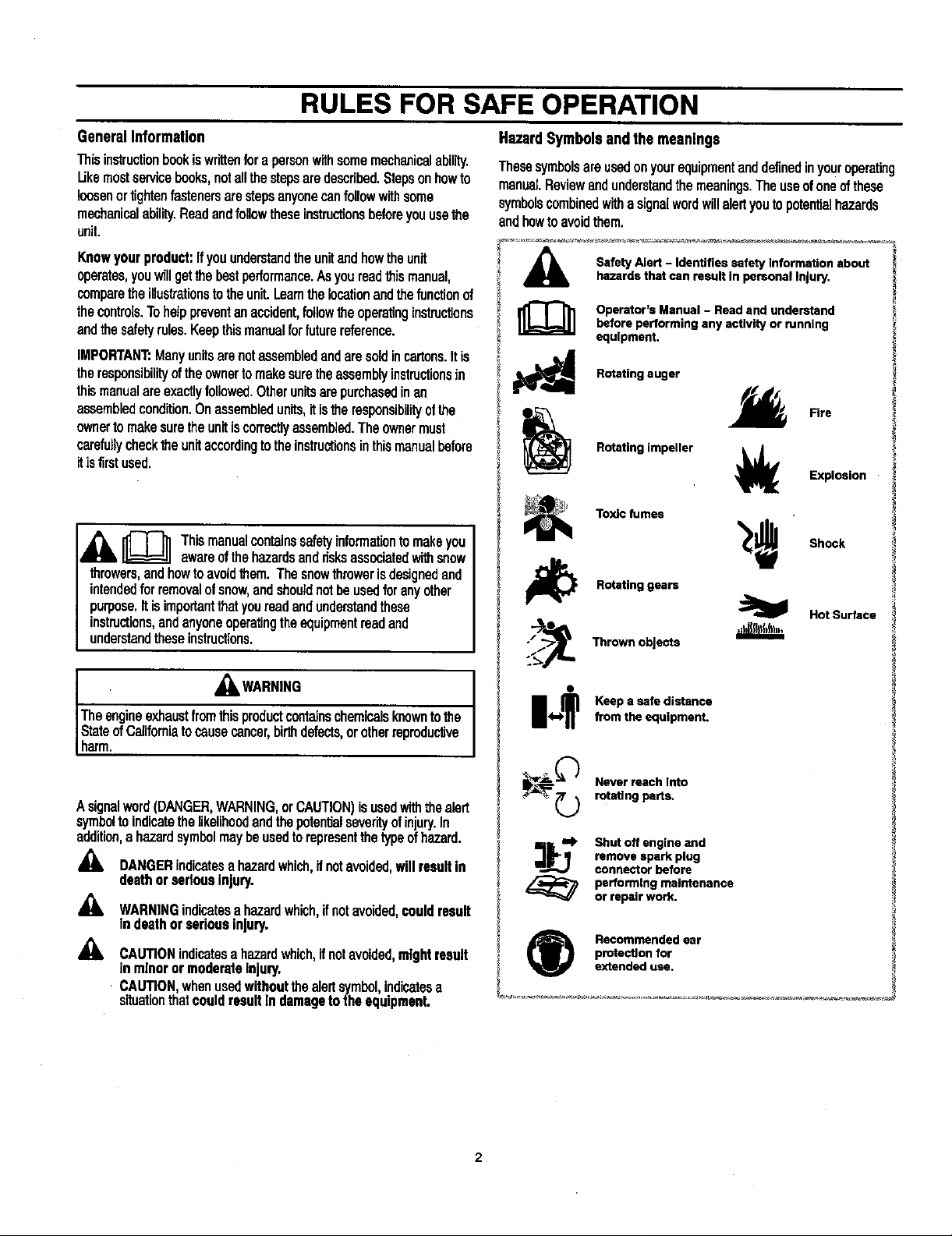
HazardSymbolsend themeanings
ThesesymbolsareusedonyourequipmentanddefinedinYouroperating
manual.Reviewandunderstandthemeanings.Theuseofoneofthese
symbolscombinedwithasignalwordwillalertyoutopotentialhazards
andhowtoavoidthem.
,_ Safety Alert - Identifies safety Information about
_]]] perator's Manual - Read and understand
_ RutaUng auger
li_ Rotating gears
/_ Thrown objects
hazards that can result in personal Injury,
before performing any activity or running
equipment.
Fire
Rotating impeller _ Explosion
Toxic fumes
Shock
HotSu_ace
• ,_WARNING
Theengineexhaustfromthisproductcontainschemicalsknowntothe
StateofCaliforniatocausecancer,birthdefects,orotherrepmducUve
harm.
A signalword(DANGER,WARNING,orCAUTION)isusedwiththealert
symboltoindicatethelikelihoodandthe potentialseverityofinjury.In
addition,a hazardsymbolmaybeusedtorepresentthetypeofhazard.
,_ DANGERindicatesahazardwhich,ifnotavoided,willresultin
deathorseriousInjury.
_1= WARNINGindicatesahazardwhich,ifnotavoided,couldresult
indeathorseriousInjury.
_. CAUTIONindicatesa hazardwhich,ifnotavoided,mightresult
in minoror moderateinjury.
CAUTION,whenusedwithoutthealertsymbolindicatesa
sifuatonthatcouldresultIn damagetothe equipment,
14._? Keep a safe distancefrom the equlpmenL
_ ever reach Into
:_mt. Shot off engine and
(_ Recommended ear
rotating parts,
remove spark plug
connector before
pertormlng maintenance
or repair work.
protection for
extended use.
2
Page 3
RULES FOR SAFE OPERATION
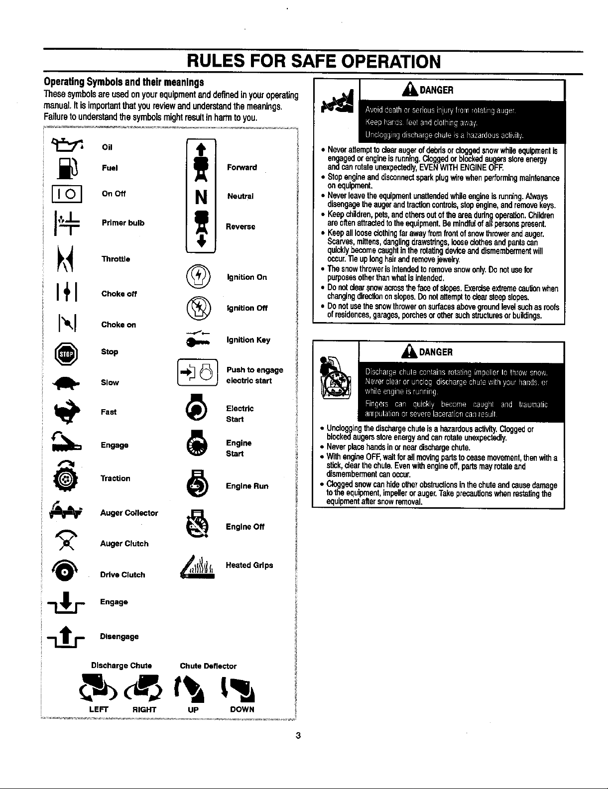
OperatingSymbolsandtheirmeanings
These symbolsare usedonyourequipmentenddefinedinyouroperating
manuel. Itisimportantthat youreviewandunderstandthe meanings.
Failureto understandthe symbolsmightresultinharmto you.
_kDANGER
Oil
_,_ Fuel
On Off
J_ Primerbulb
_\_ Throttle
I+1 Ch.oo
Ch.on
Stop
Slow
Fast _) Electric
Engage (_ Engine
Traction _) Engine Run
Forward
N Neutral
Reverse
(_ Ignition On
(_ Ignition Off
Ignition Key
-_ Pushto engage
electric start
Start
Start
• NeverattempttodearaugerofdebdsorcloggedsnowwhJeequipmentis
engagedorengineis running.Cloggedorblockedaugersstoreenergy
andcanrotateunexpectedly,EVENWITHENGINEOFf
• Stopengineanddisconnectsparkplugwirewhenperformingmaintenance
onequipment.
• Neverleavetheequipmentunattendedwhileengineisrunning.Nways
disengagetheaugerendtractioncontrols,stopengine,andremovekeys.
• Keepchildren,pets,andothersoutoftheareadudngoperation.Children
areo_enattractedtotheequipment.Beminclfutofallparsonspresent.
• Keepalllooseclothingfarawayfromfrontofsnowthrowerendauger.
Scarves,mittens,danglingdrawstdngslooseclothesandpantscan
qucklybecomecaughtintherotatingdeviceanddismembermentwill
occur."fieuplonghairendremovejewelry.
• Thesnowthrowerisintendedtoremovesnowonly.Donotusefor
purposesotherthenwhatisintended.
• Donotclearsnowacmssthefaceofslopes.Exerciseextremecautionwhen
changingdirectiononslopes.Donotattempttoclearsteepslopes.
• Donotusethesnowthroweronsurfacesabovegroundlevelsuchasreefs
ofresidences,garages,perchesorothersuchstructuresorbuildings.
_DANGER
• Uncloggingthedischargechuteisa hazardousactivity.Cloggedor
blockedaugersstoreenergyendcanrotateunexpectedly.
• Neverplacehandsinorneardischargechute.
• WithengineOFF,waitforallmovingpartstoceasemovement,thenwitha
stick,clearthechute.Evenwithengineoff,partsmayrotateend
dismembermentcanoccur.
• Cloggedsnowcanhideotherobstructionsinthechuteandcausedamage
totheequipment,impellerorauger.Takeprecautionswhenrestatingthe
equipmentaltersnowremoval.
Auger Collector _ Engine Off
_/_ Auger Clutch
Drive Clutch _ Heated Grips
Engage
_-_ Disengage
Discharge Chute Chute Deflector
LEFT RIGHT UP DOWN
Page 4
RULES FOR SAFE OPERATION
_I=DANGER
• Beawareofyourenvironmentwhileoperatingequipment.Runningover
itemssuchas,gravel,doormats,newspapars,toys,androckshidden
undersnow,canallbethrownfromchuteorjamintheauger.
• Alwaysbeawareofthedirectionthe snowisbeingthrown.Nearby
pedestrians,petsorpropertymaybeharmedbyobjectsbeingthrown.
• Familiarizeyourselfwiththeareayouplantowork.Markoffbeundadasof
walkwaysanddrivewaystopreventpropertydamagefromthrownobjects.
• Takecautionwhensnowthrowinginunfamiliarareas.Stayalertforhidden
hazardsandtraffic.
• Afterstdkinga foreignobject,turnengineOFF,w_ formovingpartsto
ceasemovement,andcheckimmediatelyfordamage.If damaged,repair
beforestartingandoperatingsnowthrower.
• W'dhengineOFF,waitformovingpadsto stopandalwaysuseastickto
cleardischargechute.
• Ifunitvibratesaboormally,turnengineOFRVibrationisgenerallya
warningoftrouble.Seaanauthorizeddealerifnecessaryfor repairs.
• Keephandsandfeetawayfromrataitnggears.
• "fieuplonghairandremovejewelry.
• Donotwearloose-fitting_thing, danglingdrawstringsoritemsthatcould
becomecaught.
,_WARNING
WHENADDINGFUEL
• TurnengineOFFandletenginecoolatleast2minutesbeforeremoving
gascap.
• RIIfueltankoutdoorsorinweli-ventilatadarea.
• Donotoverfillfueltank.
• Keepgasolineawayfromsparks,openflames,pilotlights,heat,andother
k3nitionsources.
• Checkfuellines,tank,cap,andfittingsfrequentlyfor cracksorleaks.
Replaceifnecessary.
WHENSTARTINGENGINE
• Makesuresparkplug,muffler,fuelcapandaircleanerareinplace.
• Donotcrankenginewithsparkplugremoved.
• fffuelspills,waituntilit evaporatesbeforestartingengine.
• ifenginefloods,setchoketoOPEN/RUNpostiion,placethrottleinFAST
andcrankunfitenginestarts.
WHENOPERATINGEQUIPMENT
• Donotchokecarburetorto stopengine.
WHENTRANSPORTINGEQUIPMENT
• TransportwithfueltankEMPTY.
WHENSTORING GASOLINEOR EQUIPMENTWITH FUELIN TANK
• Storeawayfromfurnaces,stoves,waterheatersorotherap_liancasthat
havepilotlightorotherignitionsourcebecausetheycanignitegasaline
vapors,
• Startandrunengineoutdoors.
• Donotstartorrunengineinenclosedarea,evenifdoomsor
windowsareopen.
WARNING
• Allowmuffler,enginecylinderandfinstocoo_beforetouching.
• Removeaccumulatedcombustiblesfrommufflerareaandcylinder
area.
• Installandmaintaininworkingorderasparkarresterbeforeusing
equipmentonforest-cavered,grass-cavered,brush-cavared
unimprovedland.ThestateofCaliforniarequiresthisSection4442of
theCaliforniaPublicResourcesCede. Otherstatesmayhavesimilar
laws.Federalewsapplyonfederalland.
_I=WARNING
• IfthereisnaturalorLPgasleakageInarea,donotstartengine.
• Donutuseprassodzedstaringfluidsbecausevaporsareflammable.
&WARN,NG
BEFORE PERFORMINGADJUSTMENTSOR REPAIRS
• Disconnectsparkplugwireandkeepitawayfromsparkplug.
WHENTESTINGFOR SPARK
• Useapprovedsparkplugtester.
• Donotcheckfor sparkwithsparkplugremoved.
Page 5
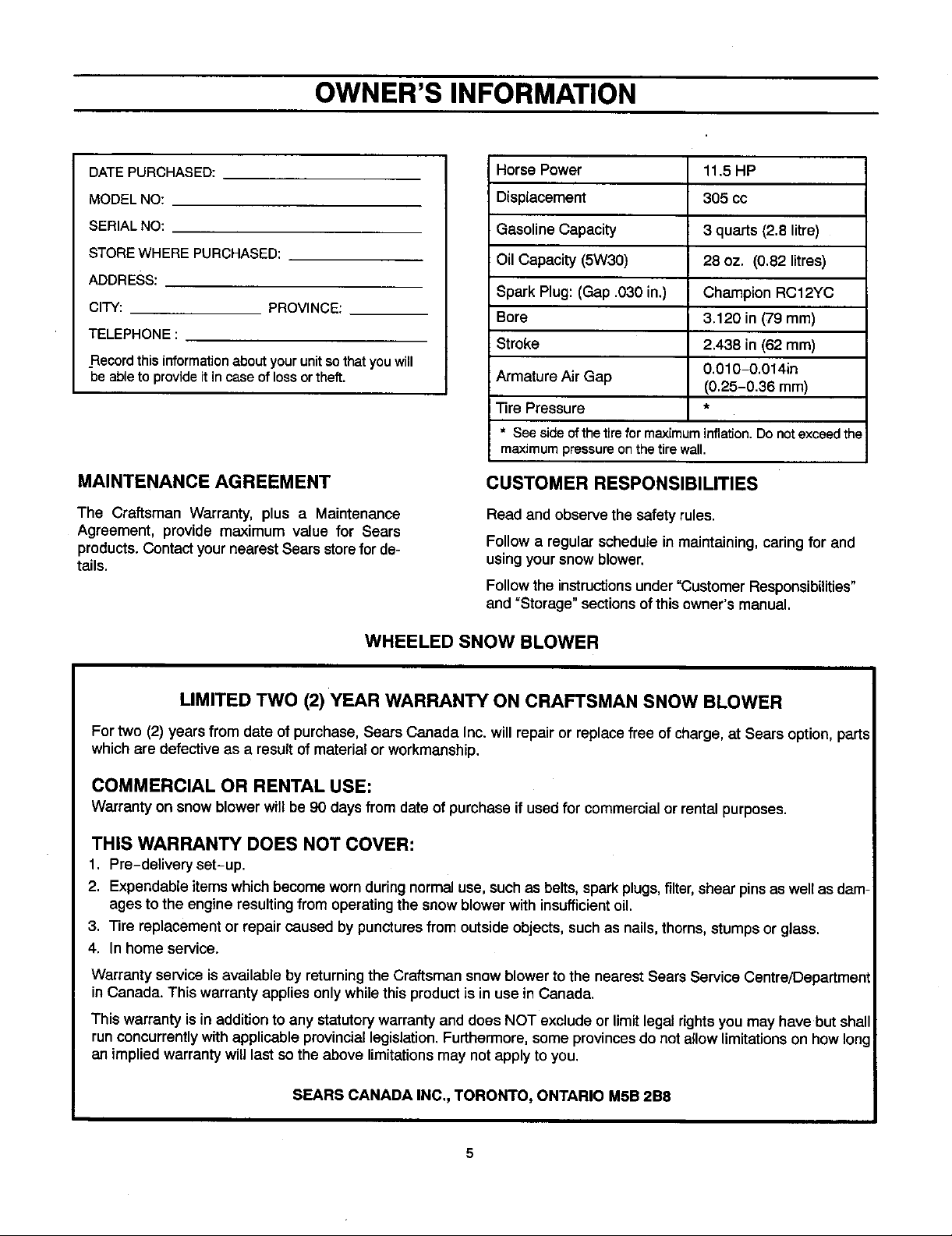
OWNER'S INFORMATION
DATE PURCHASED:
MODEL NO:
SERIAL NO:
STORE WHERE PURCHASED:
ADDRESS:
CITY: PROVINCE:
TELEPHONE :
_Recordthis information about your unit so that you will
be able to provide it in case of loss or theft.
MAINTENANCE AGREEMENT
The Craftsman Warranty, plus a Maintenance
Agreement, provide maximum value for Sears
products. Contact your nearest Sears storefor de-
tails.
Horse Power 11.5 HP
Displacement 305 cc
Gasoline Capacity
Oil Capacity (5W30)
Spark Plug: (Gap .030 in.)
Bore
Stroke
Armature Air Gap
IT ire Pressure
* Seeside ofthe tirefor maximuminflation.Do
maximumpressureonthetire wall.
3 quarts (2.8 litre)
28 oz. (0.82 litres)
Champion RC12YC
3.120 in (79 mm)
2.438 in (62 mm)
0.010-0.014in
(0.25-0.36 mm)
notexceed the
CUSTOMER RESPONSIBILITIES
Read and observethe safety rules.
Follow a regular schedule in maintaining, caring for and
using your snow blower.
Follow the instructions under "Customer Responsibilities"
and "Storage" sections of this owner's manual.
WHEELED SNOW BLOWER
LIMITED TWO (2)YEAR WARRANTY ON CRAFTSMAN SNOW BLOWER
Fortwo (2) yearsfrom date of purchase, Sears Canada Inc. willrepair orreplacefree of charge,at Sears option, parts
which are defective as a resultof materialor workmanship.
COMMERCIAL OR RENTAL USE:
Warranty on snowblower willbe 90 daysfrom date of purchase if usedfor commercialor rentalpurposes.
THIS WARRANTY DOES NOT COVER:
1. Pre-delivery set-up.
2. Expendable itemswhichbecomeworn duringnormaluse, such as belts, sparkplugs,filter,shear pinsas well asdam-
ages to the engineresultingfrom operatingthe snowblower withinsufficientoil.
3. Tire replacement or repaircaused by puncturesfrom outsideobjects,such as nails,thorns,stumpsor glass.
4. In homeservice.
Warranty service isavailable by returning the Craftsman snow blower to the nearest Sears Service Centre/Department
in Canada. This warranty applies only while this product is in use in Canada.
This warranty isin addition to any statutorywarranty and does NOT exclude or limit legal rights you may have but shall
run concurrently with applicable provincial legislation. Furthermore, some provinces do not allow limitations on how Ion
an implied warranty will last so the above limitations may not apply to you.
SEARS CANADA INC., TORONTO, ONTARIO M5B 2B8
5
Page 6
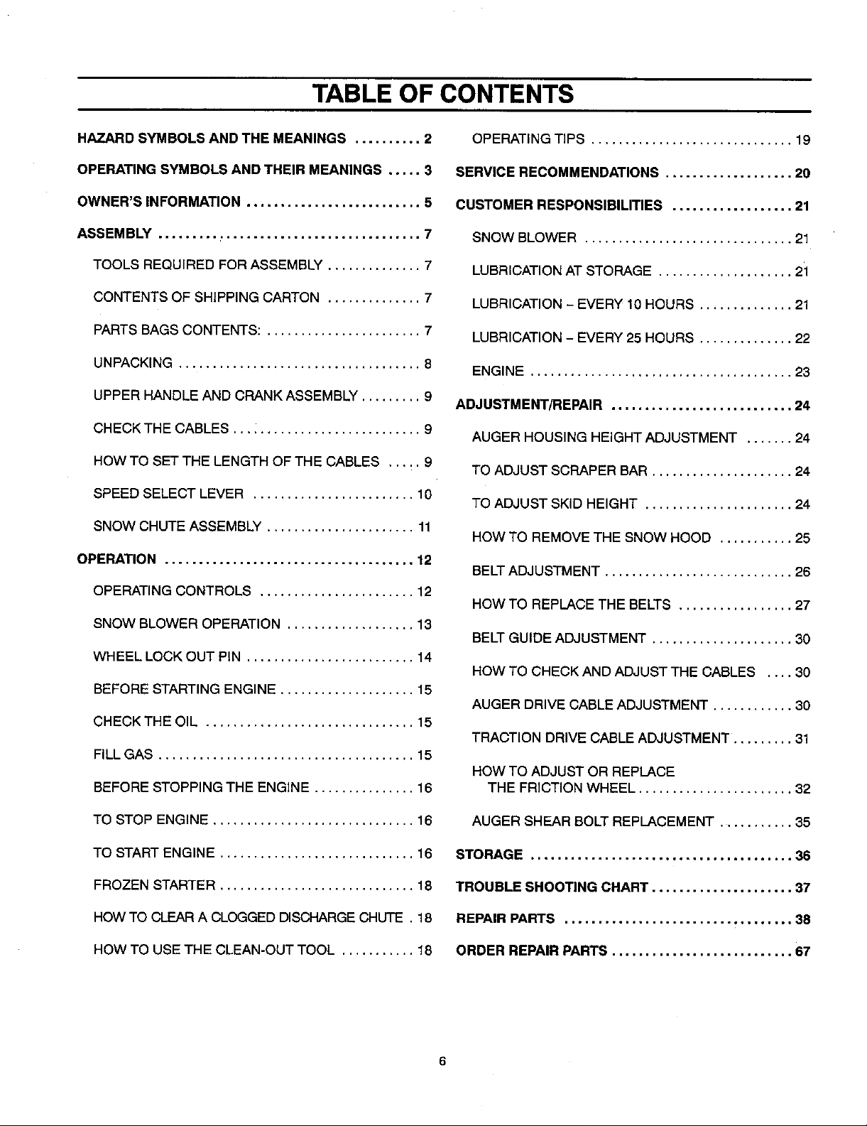
TABLE OF CONTENTS
HAZARD SYMBOLS AND THE MEANINGS .......... 2
OPERATING SYMBOLS AND THEIR MEANINGS ..... 3
OWNER'S INFORMATION .......................... 5
ASSEMBLY ....................................... 7
TOOLS REQUIRED FOR ASSEMBLY .............. 7
CONTENTS OF SHIPPING CARTON .............. 7
PARTS BAGS CONTENTS: ....................... 7
UNPACKING .................................... 8
UPPER HANDLE AND CRANK ASSEMBLY ......... 9
CHECK THE CABLES ............................ 9
HOW TO SET THE LENGTH OF THE CABLES ..... 9
SPEED SELECT LEVER ........................ 10
SNOW CHUTE ASSEMBLY ...................... 11
OPERATION ..................................... 12
OPERATING CONTROLS ....................... 12
SNOW BLOWER OPERATION ................... 13
WHEEL LOCK OUT PIN ......................... 14
BEFORE STARTING ENGINE .................... 15
CHECK THE OIL ............................... 15
FILL GAS ...................................... 15
BEFORE STOPPING THE ENGINE ............... 16
OPERATING TIPS .............................. 19
SERVICE RECOMMENDATIONS ................... 20
CUSTOMER RESPONSIBILITIES .................. 21
SNOW BLOWER ............................... 21
LUBRICATION AT STORAGE .................... 21
LUBRICATION - EVERY 10HOURS .............. 21
LUBRICATION - EVERY 25 HOURS .............. 22
ENGINE ....................................... 23
ADJUSTMENT/REPAIR ........................... 24
AUGER HOUSING HEIGHT ADJUSTMENT ....... 24
TO ADJUST SCRAPER BAR ..................... 24
TO ADJUST SKID HEIGHT ...................... 24
HOW TO REMOVE THE SNOW HOOD ........... 25
BELTADJUSTMENT ............................ 26
HOW TO REPLACE THE BELTS ................. 27
BELTGUIDE ADJUSTMENT ..................... 30
HOW TO CHECK AND ADJUST THE CABLES .... 30
AUGER DRIVE CABLE ADJUSTMENT ............ 30
TRACTION DRIVE CABLE ADJUSTMENT ......... 31
HOW TO ADJUST OR REPLACE
THE FRICTION WHEEL ....................... 32
TO STOP ENGINE .............................. 16
TO START ENGINE ............................
FROZEN STARTER ............................
HOW TO CLEAR A CLOGGED DISCHARGE CHUTE
HOW TO USE THE CLEAN-OUT TOOL ..........
.16
.18
.18
.18
AUGER SHEAR BOLT REPLACEMENT ........... 35
STORAGE ....................................... 36
TROUBLE SHOOTING CHART ..................... 37
REPAIR PARTS .................................. 38
ORDER REPAIR PARTS ........................... 67
Page 7
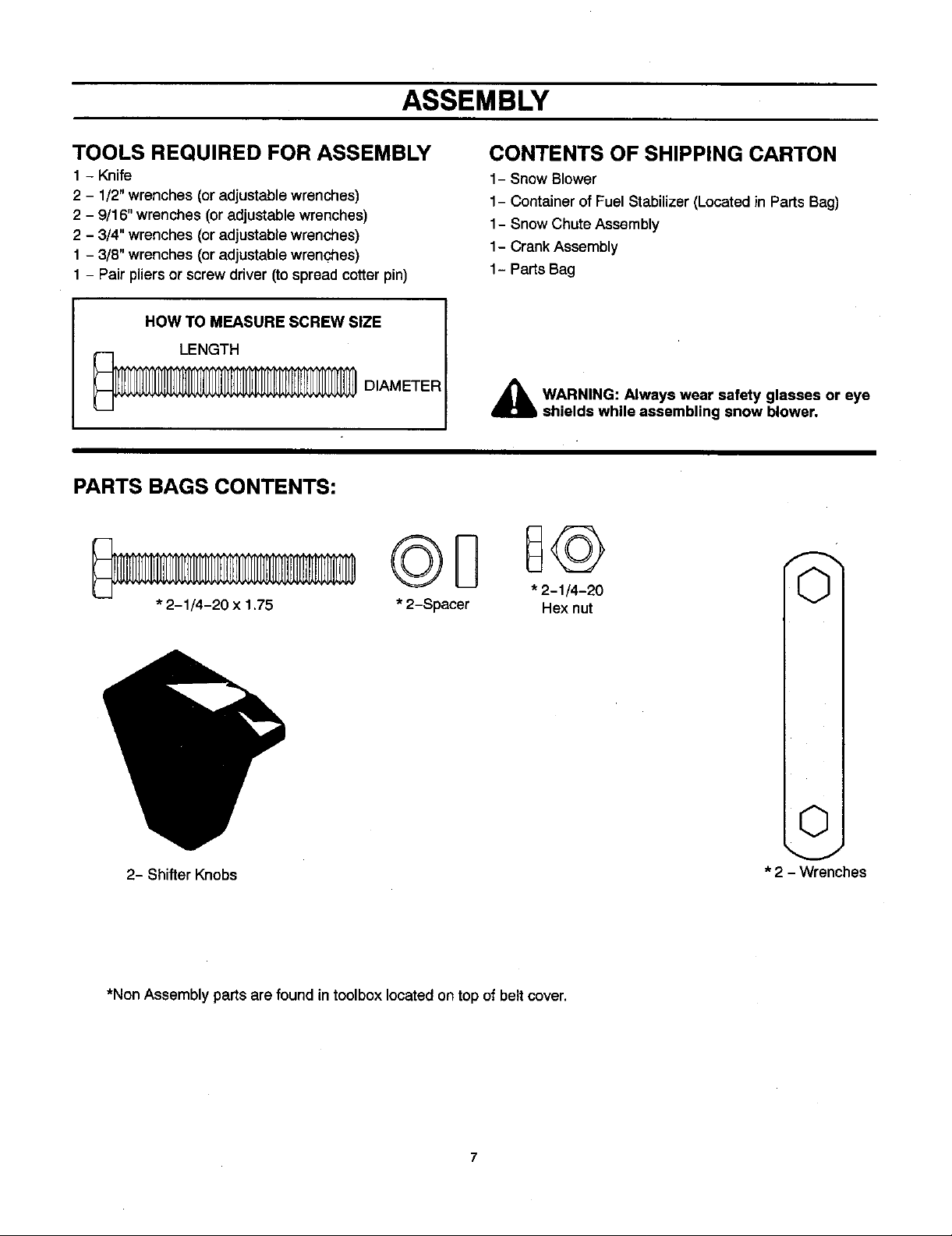
ASSEMBLY
TOOLS REQUIRED FOR ASSEMBLY
1 - Knife
2 - 1/2" wrenches (or adjustable wrenches)
2 - 9/16" wrenches (or adjustable wrenches)
2 - 3/4" wrenches (or adjustable wrenches)
1 - 3/8" wrenches (or adjustable wrenches)
1 - Pair pliers or screw driver (to spread cotter pin)
HOW TO MEASURE SCREW SIZE
LENGTH
_ DIAMETER
PARTS BAGS CONTENTS:
* 2-1/4-20 x 1.75
"2-Spacer * 2H-Jx/4n"u20 O
CONTENTS OF SHIPPING CARTON
1- Snow Blower
1- Container of Fuel Stabilizer (Located in Parts Bag)
1- Snow Chute Assembly
1- Crank Assembly
1- Parts Bag
_b WARNING: Always wear safety glasses or eye
shields while assembling snow blower.
2- Shifter Knobs
*Non Assembly parts are found intoolbox locatedon top of belt cover.
7
©
* 2 - Wrenches
Page 8
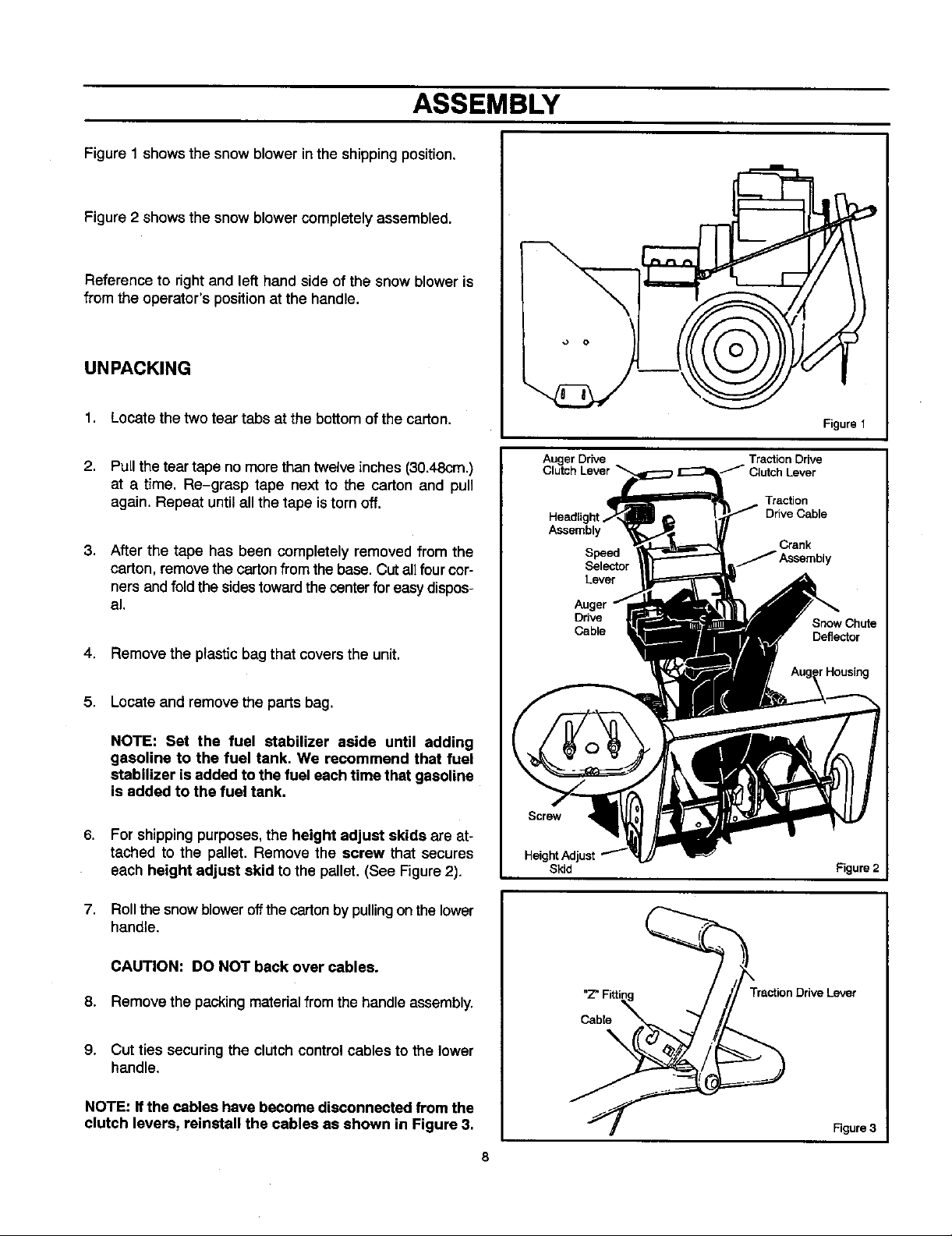
ASSEMBLY
Figure 1 shows the snow blower in the shippingposition.
Figure 2 shows the snow blower completely assembled.
Reference to right and left hand side of the snow blower is
from the operator's position at the handle.
UNPACKING
1. Locate the twotear tabs at the bottomofthe carton,
2. Pull the tear tape no more than twelve inches (30.48cm.)
at a time. Re-grasp tape next to the carton and pull
again. Repeat until all the tape is torn off.
3. After the tape has been completely removed from the
carton, remove thecarton from the base. Cut all four cor-
ners andfold the sidestoward the center for easy dispos-
al.
4. Remove the plastic bag that covers the unit.
5. Locate and remove the parts bag.
NOTE: Set the fuel stabilizer aside until adding
gasoline to the fuel tank. We recommend that fuel
stabilizer isadded to the fuel each time that gasoline
is added to the fuel tank.
6. For shipping purposes, the height adjust skids are at-
tached to the pallet. Remove the screw that secures
each height adjust skid to the pallet. (See Figure2).
7. Roll the snow blower off the carton by pulling onthe lower
handle.
Auger Drive Traction Drive
Clutch Lever
Traction
Drive Cable
Assembly
Speed J Assembly
Selector
Lever
Auger
Drive
Cable
Screw
Skid
Crank
Snow Chute
Deflector
_rHousing
Figure 2
CAUTION: DO NOT back over cables.
8. Remove the packing materialfrom the handleassembly.
9. Cut ties securing the clutch control cables to the lower
handle.
NOTE: Ifthe cables have become disconnected from the
clutch levers, reinstall the cables as shown in Figure 3.
Traction Drive Lever
Cable
\
Figure 3
Page 9
ASSEMBLY
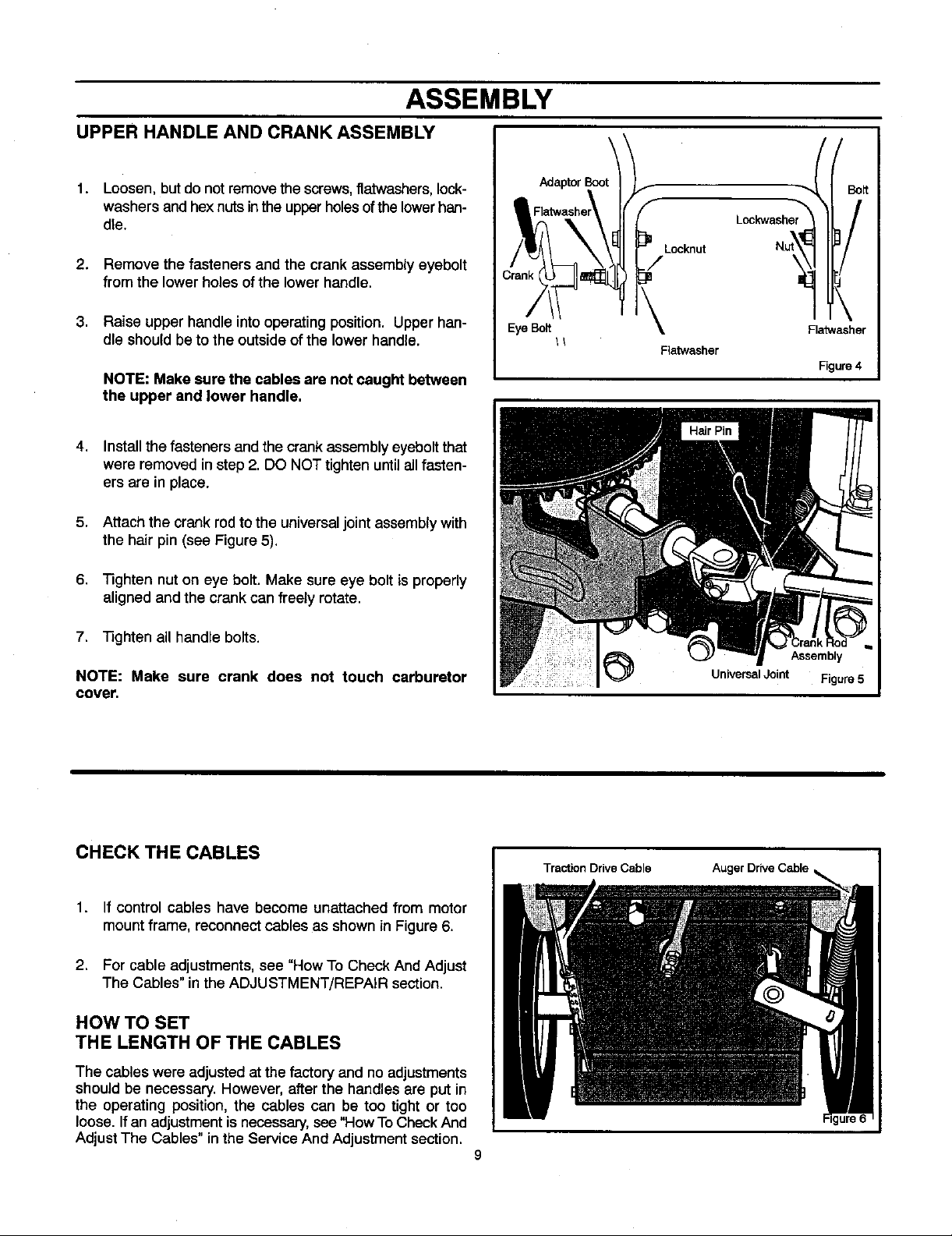
UPPER HANDLE AND CRANKASSEMBLY
1. Loosen, but do not remove the screws, flatwashers, lock-
washers and hex nuts inthe upperholes ofthe lower han-
dle.
2. Remove the fasteners and the crank assembly eyebolt
from the lower holes of the lower handle.
3. Raise upper handle into operating position. Upper han-
dle should beto the outside of the lower handle.
NOTE: Make sure the cables are not caught between
the upper and lower handle.
4. Install the fasteners and the crank assembly eyebolt that
were removed instep 2.DO NOT tighten until all fasten-
ers are in place.
5. Attach the crank rod to the universal joint assembly with
the hair pin (see Figure 5).
Adaptor Boot!
_ Flatwashe_
Eye Bolt
f
F
D,
Locknut
Fiatwasher
[/
\ Bo_
Lockwasher_
!
\
\
Flatwasher
Figure 4
6. Tighten nut on eye bolt. Make sure eye bolt is properly
aligned and the crank can freely rotate.
7. Tighten all handle bolts.
NOTE: Make sure crank does not touch carburetor
cover.
CHECKTHECABLES
1. If control cables have become unattached from motor
mount frame, reconnect cables as shown in Figure 6.
2. For cable adjustments, see "How To Check And Adjust
The Cables" in the ADJUSTMENT/REPAIR section.
HOW TO SET
THE LENGTH OF THE CABLES
Traction DriveCable
Assembly
Universal Joint Figure 5
Auger Drive Cable
The cables were adjusted atthe factory and no adjustments
should be necessary. However, after the handles are put in
the operating position, the cables can be too tight or too
loose. Ifan adjustment is necessary, see "How To Check And
Adjust The Cables" in the Service And Adjustment section.
9
Page 10
ASSEMBLY
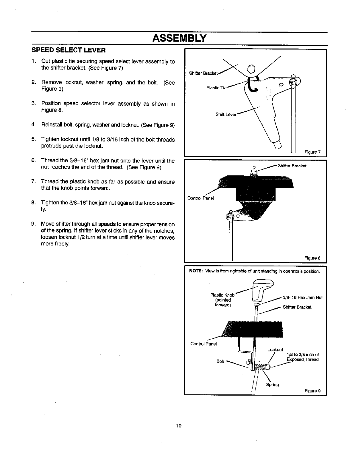
SPEED SELECT LEVER
1, Cut plastic tie securing speed select lever assembly to
the shifterbracket. (See Figure 7)
2. Remove Iocknut, washer, spring, and the bolt. (See
Figure 9)
3. Position speed selector lever assembly as shown in
Figure 8.
4. Reinstall bolt, spring, washer and Iocknut. (See Figure 9)
5. Tighten Iocknut until 1/8 to 3/16 inch of the bolt threads
protrude past the locknut.
6. Thread the 3/8-16" hex jam nut onto the lever until the
nut reaches the end ofthe thread. (See Figure 9)
7. Thread the plastic knob as far as possible and ensure
that the knob points forward.
8. Tighten the 3/8-16" hex jam nut against the knob secure-
ly.
Shifter Bracke_
Figure7
Control Panel
9,
Move shifterthroughall speedsto ensure propertension
of the spring. If shifter lever sticks in any of the notches,
loosen Iocknut 1/2turn at a time until shifter lever moves
more freely.
Figure 8
NOTE: View is trorn rightside of unit standing inoperator's position.
Plastic Knob"_,_-'_ 3"8 6" "
(pointed (.J--_// / -1 Hex,Jam Nut
forward) _ Shifter Bracket
Control Panel
Lccknut
1/8 to 3/8 inch of
Spring
Figure 9
lO
Page 11
ASSEMBLY
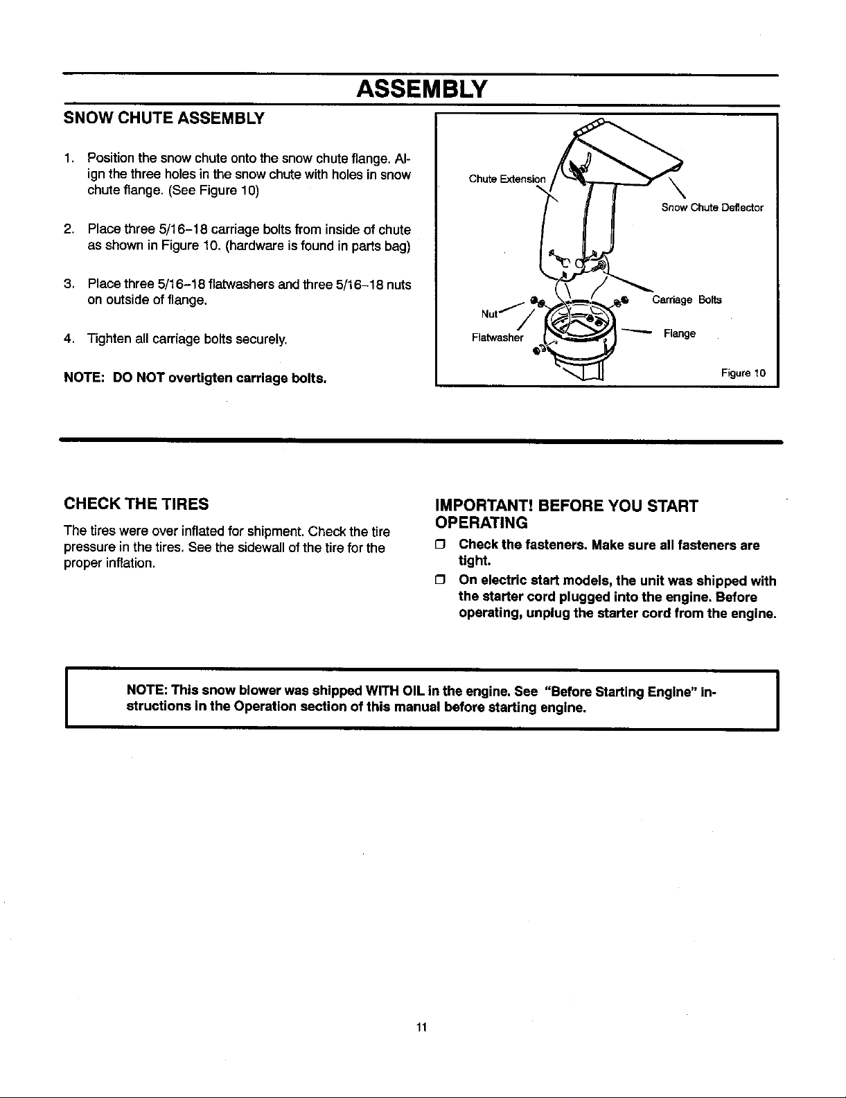
SNOW CHUTE ASSEMBLY
1. Positionthe snow chute ontothe snow chuteflange, Al-
ignthe three holesinthe snow chutewith holesin snow
chuteflange. (See Figure 10)
2, Place three 5/16-18 carriage boltsfrom insideof chute
as shown in Figure10. (hardware isfound in partsbag)
3. Place three 5/16-18 flatwashers and three5/16-18 nuts
on outside offlange.
Chute Extension
\
Snow Chute Deflector
Carriage Bolts
4. Tighten all carriage boltssecurely.
NOTE: DO NOT overtigten carriage bolts.
CHECK THE TIRES
The tires were over inflatedfor shipment.Check the tire
pressure in the tires. See the sidewall of the tire for the
proper inflation.
NOTE: This snow blower was shipped WITH OIL in the engine. See "Before Starting Engine" in-
structions In the Operation section of this manual before starting engine.
Flatwasher
IMPORTANT! BEFORE YOU START
OPERATING
Check the fasteners. Make sure all fasteners are
tight.
O On electric start models, the unit was shipped with
the starter cord plugged into the engine. Before
operating, unplug the starter cord from the engine.
"-"'- Flange
Figure 10
I
11
Page 12
OPERATION
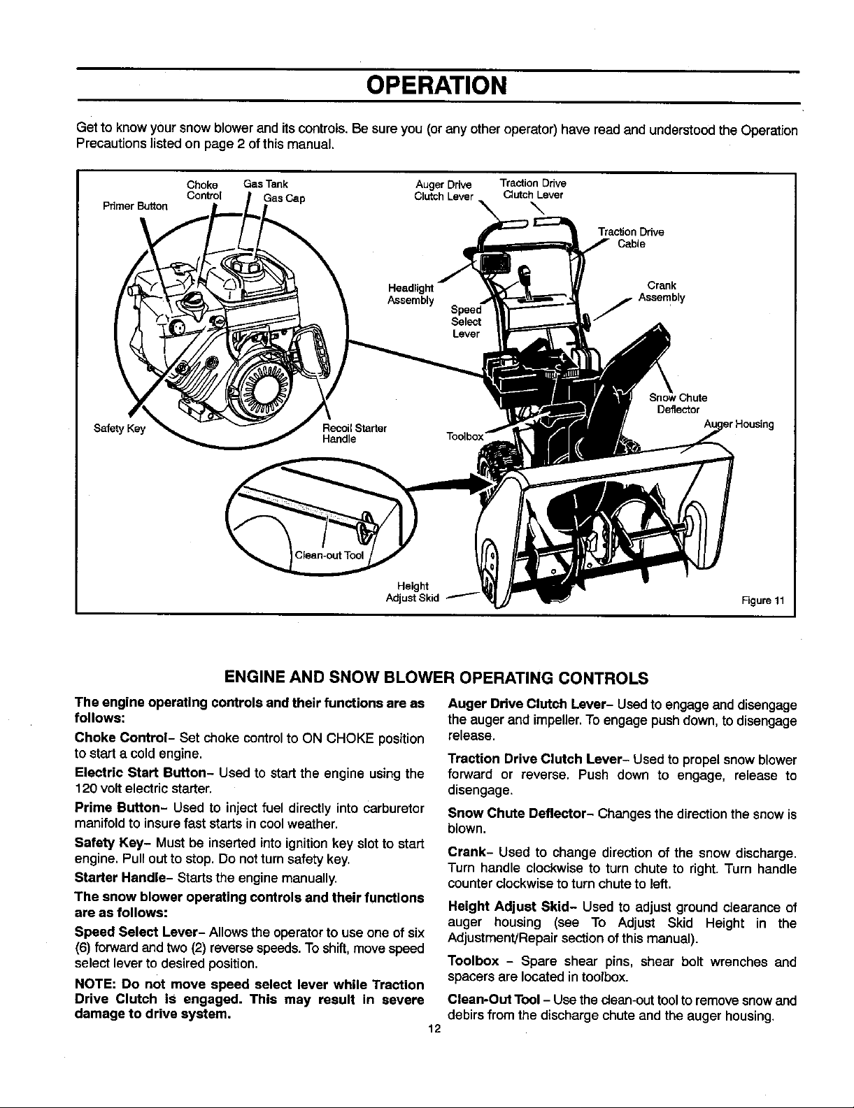
Get to know your snow blower and its controls. Be sureyou (or any other operator) have read and understoodthe Operation
Precautions listed on page 2 of this manual.
Choke Gas Tank Auger Drive Traction Drive
Primer Button
Safety Key
Control Clutch Lever Clutch Lever
\
Traction Ddve
Cable
Crank
Assembly
Deflector
Height
Adjust Skid Figure 11
ENGINE AND SNOW BLOWER OPERATING CONTROLS
The engine operating controls and their functions are as
follows:
Choke Control- Set choke controlto ON CHOKE position
to starta coldengine.
Electric Start Button- Used to startthe engine usingthe
120 voltelectric starter.
Prime Button- Used to inject fuel directly into carburetor
manifoldto insurefast starts incoolweather.
Safety Key- Must be inserted intoignitionkey slot to start
engine. Pull outto stop. Do notturnsafety key.
Starter Handle- Startsthe engine manually.
The snow blower operating controls and their functions
are as follows:
Speed Select Lever- Allows the operatorto use one ofsix
(6) forward and two(2) reversespeeds.To shift,movespeed
select lever to desired position.
NOTE: Do not move speed select lever while Traction
Drive Clutch is engaged. This may result in severe
damage to drive system.
Auger Drive Clutch Lever- Used to engage and disengage
the augerand impeller.Toengage pushdown, to disengage
release.
Traction Drive Clutch Lever- Used to propel snow blower
forward or reverse. Push down to engage, release to
disengage.
Snow Chute Deflector- Changes the direction the snow is
blown.
Crank- Used to change direction of the snow discharge.
Turn handle clockwise to turn chute to right. Turn handle
counter clockwise to turn chute to left.
Height Adjust Skid- Used to adjust ground clearance of
auger housing (see To Adjust Skid Height in the
Adjustment/Repairsectionofthis manual).
Toolbox - Spare shear pins, shear bolt wrenches and
spacers are located intoolbox.
Clean-Out Tool - Use the clean-outtoolto removesnowand
debirs from the discharge chuteand the auger housing.
12
Page 13
OPERATION
The operation of any snow blower can result in foreign objects being thrown into the eyes,which canresult in severe eye damage. Always wear safety glasses or eye shields before beginning snow blower
Operation. We recommend standard safety glasses or Wide Vision Safety Mask for over spectacles.
SNOW BLOWER OPERATION
The most effective use of the snowblower willbe established
by experience, taking into consideration the terrain, wind
conditions and building location which will determine the
direction of the discharge chute.
NOTE: Do not blow snow towards a building as hidden
objects could be blown with sufficient force to cause
damage.
1. Start theengine as described in section"To Start Engine"
(see Figure 13).
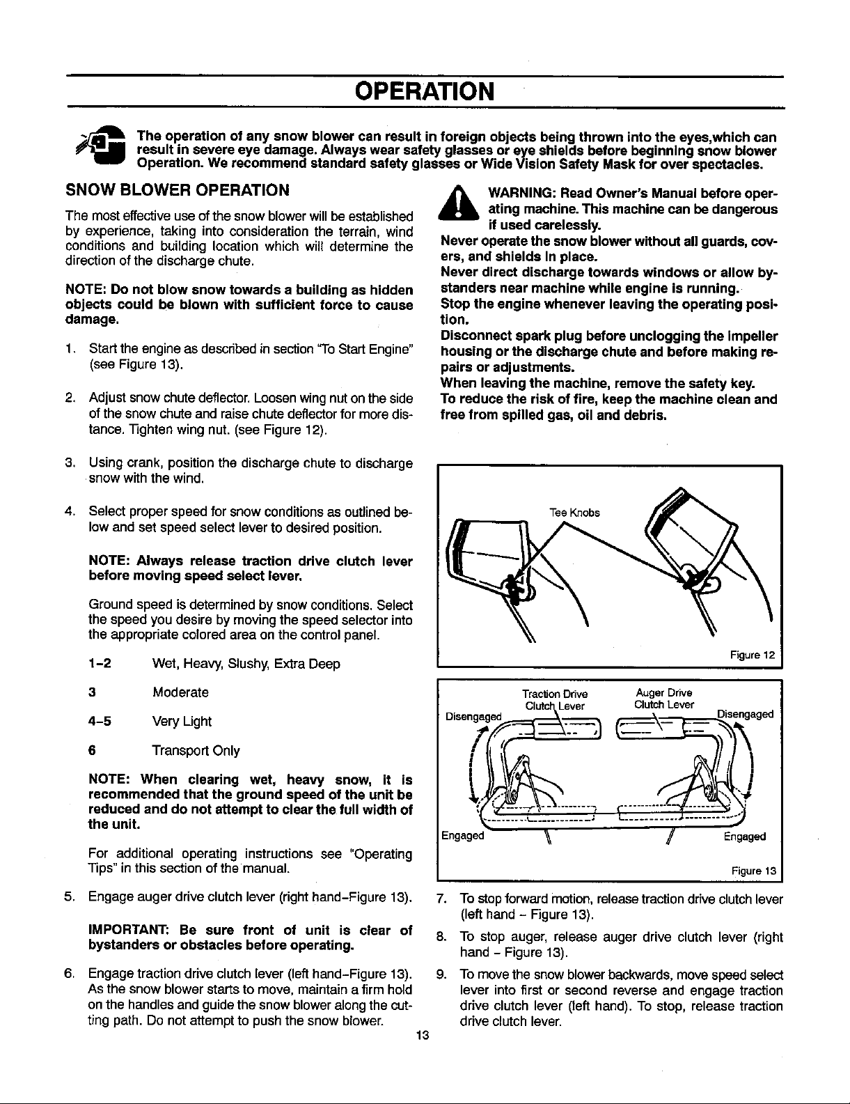
2. Adjust snowchute deflector. Loosen wingnut on the side
of the snow chute and raise chute deflector for more dis-
tance. Tighten wing nut. (see Figure 12).
3.
Using crank, position the discharge chute to discharge
snow with the wind.
,_ WARNING: Read Owner's Manual before oper-
ating machine.This machine can be dangerous
if used carelessly.
Never operate the snow blowerwithout all guards, cov-
ers, and shields In place.
Never direct discharge towards windows or allow by-
standers near machine while engine is running.
Stop the engine whenever leaving the operating posi-
tion.
Disconnect spark plug before unclogging the impeller
housing or the discharge chute and before making re-
pairs or adjustments.
When leaving the machine, remove the safety key.
To reduce the risk of fire, keep the machine clean and
free from spilled gas, oil and debris.
4.
Select proper speed for snow conditions as outlinedbe-
low and set speed select lever to desiredposition.
NOTE: Always release traction drive clutch lever
before moving speed select lever.
Ground speed is determined by snow conditions. Select
the speed you desire by moving the speed selector into
the appropriate colored area on the control panel.
1-2 Wet, Heavy, Slushy, Extra Deep
3 Moderate
4-5 Very Ught
6 Transport Only
NOTE: When clearing wet, heavy snow, it is
recommended that the ground speed of the unit be
reduced and do not attempt to clear the full width of
the unit.
For additional operating instructions see "Operating
Tips" in this section of the manual.
5. Engage auger drive clutch lever (right hand-Figure 13).
IMPORTANT: Be sure front of unit is clear of
bystanders or obstacles before operating.
6,
Engage tractiondrive clutch lever (lefthand-Figure 13).
As the snow blower starts to move, maintain a firm hold
on the handles and guide the snow blower alongthe cut-
ting path. Do not attempt to push the snow blower.
Tee Knobs
Figure 12
Traction Ddve Auger Drive
ged
Disengaged_ .._._ ClutchLever is_l_ a
Engaged '_ J Engaged
Figure 13
7. To stop forwardmotion, releasetraction drive clutch lever
(lefthand - Figure 13).
8. To stop auger, release auger drive clutch lever (right
hand - Figure 13).
g. To movethe snowblower backwards, movespeed select
lever into first or second reverse and engage traction
drive clutch lever (left hand). To stop, release traction
drive clutch lever.
13
Page 14
OPERATION
WHEEL LOCK OUT PIN
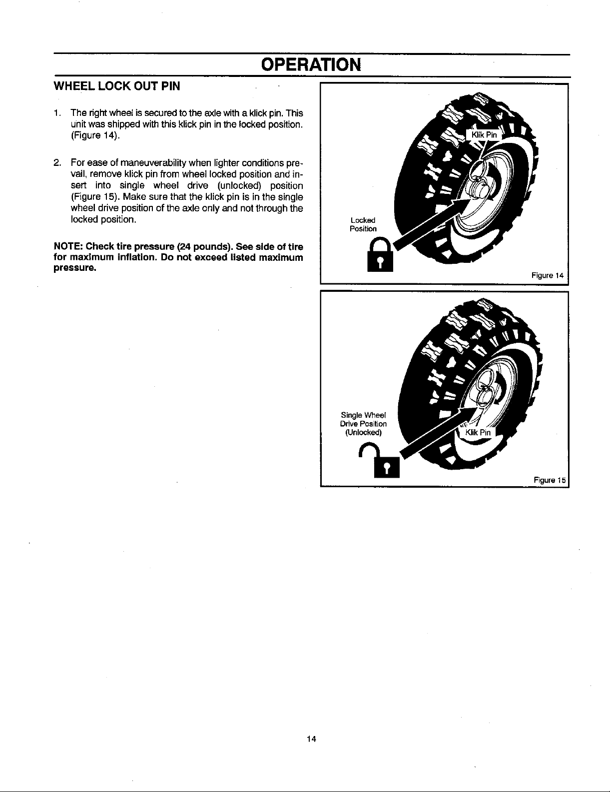
1. The rightwheel issecured to the axle witha klickpin.This
unit was shipped with this klick pin in the locked position.
(Figure 14).
2. For ease of maneuverability when lighter conditions pre-
vail, remove klick pin from wheel locked position and in-
sen into single wheel drive (unlocked) position
(Figure 15). Make sure that the klick pin is in the single
wheel drive position of the axle only and not through the
locked position.
NOTE: Check tire pressure (24 pounds). See side of tire
for maximum inflation, Do not exceed listed maximum
pressure.
Locked
Position
Figure 14
Single Wheel
Drive Position
(Unlocked)
Figure 15
14
Page 15
OPERATION
BEFORE STARTING ENGINE 1.
Check the oil
NOTE: The engine was shipped from the factory filled
with oil. Check the level of the oil Add oil as needed.
1,
Make sure the unit islevel. Use a high quality detergent
oil classified "For Service SG, SH, SJ, SL, or higher".
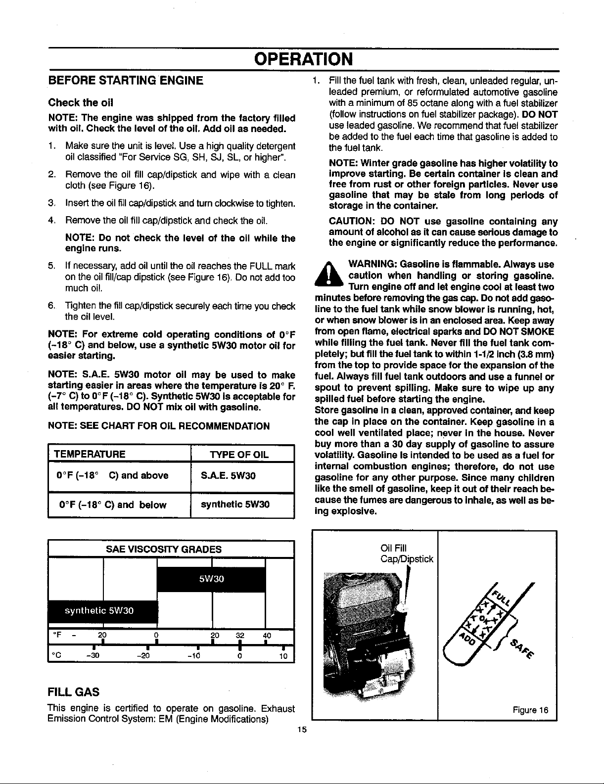
2,
Remove the oil fill cap/dipstick and wipe with a clean
cloth (see Figure 16).
3. Insert the oilfillcap/dipstick and turn clockwise to tighten.
4. Remove the oil fill cap/dipstick and check the oil
NOTE: Do not check the level of the oil while the
engine runs.
5. If necessary, add oiluntil the oil reaches the FULL mark
on the oil fill/capdipstick (see Figure 16). Do not add too
much oil.
6. Tighten the fill cap/dipstick securelyeach time you check
the oil level.
NOTE: For extreme cold operating conditions of 0°F
(-18 ° C) and below, use a synthetic 5W30 motor oil for
easier starting.
NOTE: S.A.E. 5W30 motor oil may be used to make
starting easier in areas where the temperature is 20 ° F.
(-7 ° C) to O°F (-18 ° C). Synthetic 5W30 is acceptable for
all temperatures. DO NOT mix oil with gasoline,
NOTE: SEE CHART FOR OIL RECOMMENDATION
TEMPERATURE TYPE OF OIL
0°F (-18 ° C) and above S.A.E. 5W30
0°F (-18 ° C) and below synthetic 5W30
Fillthefuel tank withfresh, clean, unleadedregular, un-
leaded premium, or reformulated automotive gasoline
with a minimum of 85 octane along with a fuel stabilizer
(follow instructions onfuel stabilizer package). DO NOT
use leaded gasoline. We recommend that fuel stabilizer
be added to the fuel each time that gasoline is added to
the fuel tank.
NOTE: Winter grade gasoline has higher volatility to
improve starting. Be certain container is clean and
free from rust or other foreign particles. Never use
gasoline that may be stale from long periods of
storage in the container.
CAUTION: DO NOT use gasoline containing any
amount of alcohol as it can cause sedous damage to
the engine or significantly reduce the performance.
_k ARNING: Gasoline isflammable. Always use
minutes before removingthe gas cap. Do not add gaso-
line to the fuel tank while snow blower is running, hot,
or when snow blower is in an enclosed area. Keep away
from open flame, electrical sparks and DO NOT SMOKE
while filling the fuel tank. Never fill the fuel tank com-
pletely; but fill the fueltank to within 1-1/2 inch (3.8 mm)
from the top to provide space for the expansion of the
fuel. Always fill fuel tank outdoors and use a funnel or
spout to prevent spilling, Make sure to wipe up any
spilled fuel before starting the engine.
Store gasoline ina clean, approved container, and keep
the cap in place on the container. Keep gasoline in a
cool well ventilated place; never in the house. Never
buy more than a 30 day supply of gasoline to assure
volatility. Gasoline Is intended to be used as a fuel for
internal combustion engines; therefore, do not use
gasoline for any other purpose. Since many children
like the smell of gasoline, keep it out of their reach be-
cause the fumes are dangerous to inhale, as well as be-
ing explosive.
caution when handling or storing gasoline.
Turn engine off and let engine cool at least two
SAE VISCOSITY GRADES
=,- WJ JBJ
°F 20 0 20 32 40
°C -30 -20 -10 0 10
FILL GAS
This engine is certified to operate on gasoline. Exhaust
Emission Control System: EM (Engine Modifications)
I I I • •
• i ¶ • •
Oil Fill
Cap/Dipstick
%
Figure 16
15
Page 16
OPERATION
BEFORE STOPPING THE ENGINE
Run the engine fora few minutes to help dry off any moisture
on the engine.
TO STOP ENGINE
CAUTION: To stop the engine, do not move the choke
control to CHOKE position. Backfire or engine damage
can occur.
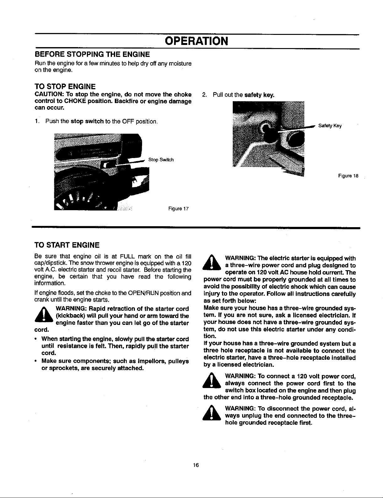
2. Pull out the safety key.
1. Push the stop switch to the OFF position.
Stop Switch
Figure 17
TO START ENGINE
Be sure that engine oil is at FULL mark on the oil fill
cap/dipstick. The snowthrower engine is equipped with a 120
volt A.C. electric starter and recoil starter. Before starting the
engine, be certain that you have read the following
information.
If engine floods, set the choke to the OPEN/RUN position and
crank until the engine starts.
_lb WARNING: Rapid retraction of the starter cord(kickback) will pull your hand or arm toward the
engine faster than you can let go of the starter
cord.
• When starting the engine, slowly pull the starter cord
until resistance is felt. Then rapidly pull the starter
cord.
• Make sure components; such as impellore, pulleys
or sprockets, are securely attached.
Safety Key
Figure 18
_lb WARNING: The electric starter is equipped with
power cord must be properly grounded at all times to
avoid the possibility of electric shock which can cause
injury to the operator. Follow all instructions carefully
as set forth below:
Make sure your house has a three-wire grounded sys-
tem. If you ere not sure, ask • licensed electrician. If
your house does not have a three-wire grounded sys-
tem, do not use this electric starter under any condi-
tion.
If your house has a three-wire grounded system but a
three hole receptacle is not available to connect the
electric starter, have a three-hole receptacle installed
by a licensed electrician.
a three-wire power cord and plug designed to
operate on 120 volt AC house hold current. The
_IL WARNING: To connect a 120 volt power cord,
the other end into a three-hole grounded receptacle.
16
always connect the power cord first to the
switch box located on the engine and then plug
WARNING: To disconnect the power cord, al-
ways unplug the end connected to the three-
hole grounded receptacle first.
Page 17
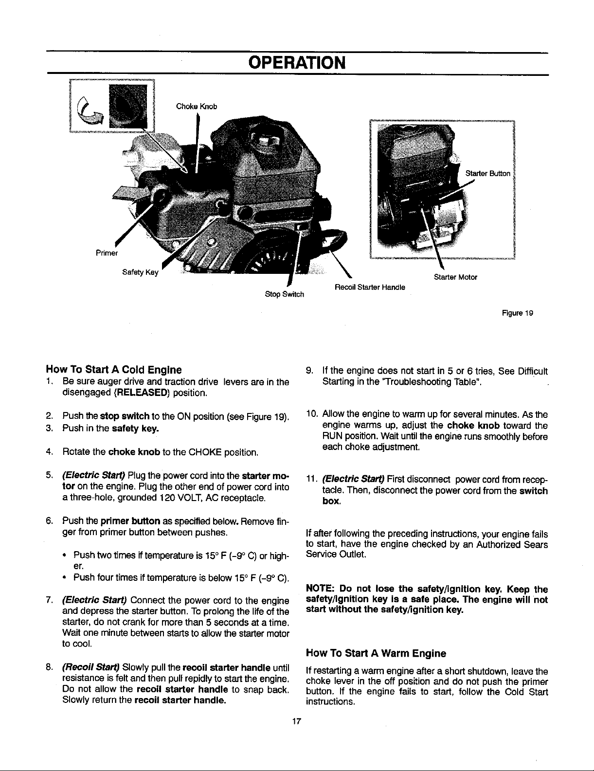
Primer
OPERATION
Choke Knob
Safety Key
Stop Switch
How To Start A Cold Engine
1, Be sure auger drive and tractiondrive levers are in the
disengaged (RELEASED) position.
2. Push thestop switch to the ON position (seeFigure 19).
3. Push in the safety key.
4. Rotate the choke knob to the CHOKE position.
5. (Electric Start) Plug the power cord intothe starter mo-
tor on the engine. Plug the otherend of power cord into
a three-hole, grounded 120 VOLT, AC receptacle.
6. Push theprimer button asspecifiedbelow. Remove fin-
ger from primer button between pushes.
• Push two times iftemperutureis 15° F (-9 ° (3)or high-
er.
• Push fourtimes iftemperature is below 15° F (-9° C).
7,
(Electric Start) Connect the power cord to the engine
and depress the starterbutton. To prolongthe lifeof the
starter,do not crankfor more than 5 seconds at a time.
Wait one minute between startsto allowthestartermotor
to cool.
8.
(Recoil Start) Slowlypull therecoil starter handle until
resistanceisfelt andthen pullrepidlyto startthe engine.
Do not allow the recoil starter handle to snap back.
Slowlyreturn the recoil starter handle.
Starter Motor
Recoil Starter Handle
Figure 19
9. If the engine does not start in 5 or 6 tries, See Difficult
Starting inthe 'Troubleshooting Table".
10. Allow the engine to warm up for several minutes. As the
engine warms up, adjust the choke knob toward the
RUN position. Walt untilthe engine runs smoothly before
each choke adjustment.
11. (Electric Start) First disconnect power cordfrom recep-
tacle. Then, disconnectthe powercord from the switch
box.
If after following the preceding instructions,your engine fails
to start, have the engine checked by an Authorized Sears
Service Outlet.
NOTE: Do not lose the safety/ignition key. Keep the
safety/ignition key is a safe place. The engine will not
start without the safety/ignition key.
How To Start A Warm Engine
Ifrestarting a warm engine aftera shortshutdown,leave the
choke lever in the off positionand do not push the primer
button. If the engine fails to start, follow the Cold Start
instructions.
17
Page 18
OPERATION
FROZEN STARTER
If the starter is frozen and will not turn engine:
1. Pull as much rope out of the starter as possible.
2. Release the starter handle and let it snap back against
the starter. Repeat until the engine starts.
Warm engines will cause condensation in cold weather. To
help prevent possible freeze-up of recoil starter and engine
controls, proceed as follows after each snow removal job.
1. With engine off, allow engine to cool for several minutes.
2. Pull starter rope very slowly until resistance is felt, then
stop. Allow the starter rope to recoil. Repeat three times.
3. With the engine not running, wipe all snow and moisture
from the carburetor cover in area of control levers. Also
move choke knob and starter handle several times.
,_ WARNING: Never run engine indoors or In en-
AND DEADLY GAS. Keep hands, feet, hair and loose
clothing away from any moving parts on engine and
snow thrower.
• Engine parts, especially the muffler, become ex-
• Never allow children to operate the snow thrower.
• Keep the area of operation clear of all persons, partic-
• Never leave the snow blower unattended while the
IMPORTANT: After each use of the snow blower, stop the
engine, remove the safety/ignition key, remove all
accumulated snow from the snow blower and wipe
clean. Store the snow blower in a protected area.
NOTE: Never cover snow blower while engine and
exhaust area are still warm.
closed, poorly ventilated areas. Engine exhaust
contains CARBON MONOXIDE, AN ODORLESS
tremely hot. Severe thermal burns can occur on con-
tact. Allow the engine to cool before touching.
Never allow adults to operate the snow blower with-
out proper instruction,
ularly small children and pets.
engine is running. Anyone operating the engine or
equipment must carefully read and understand the
operating instructions.
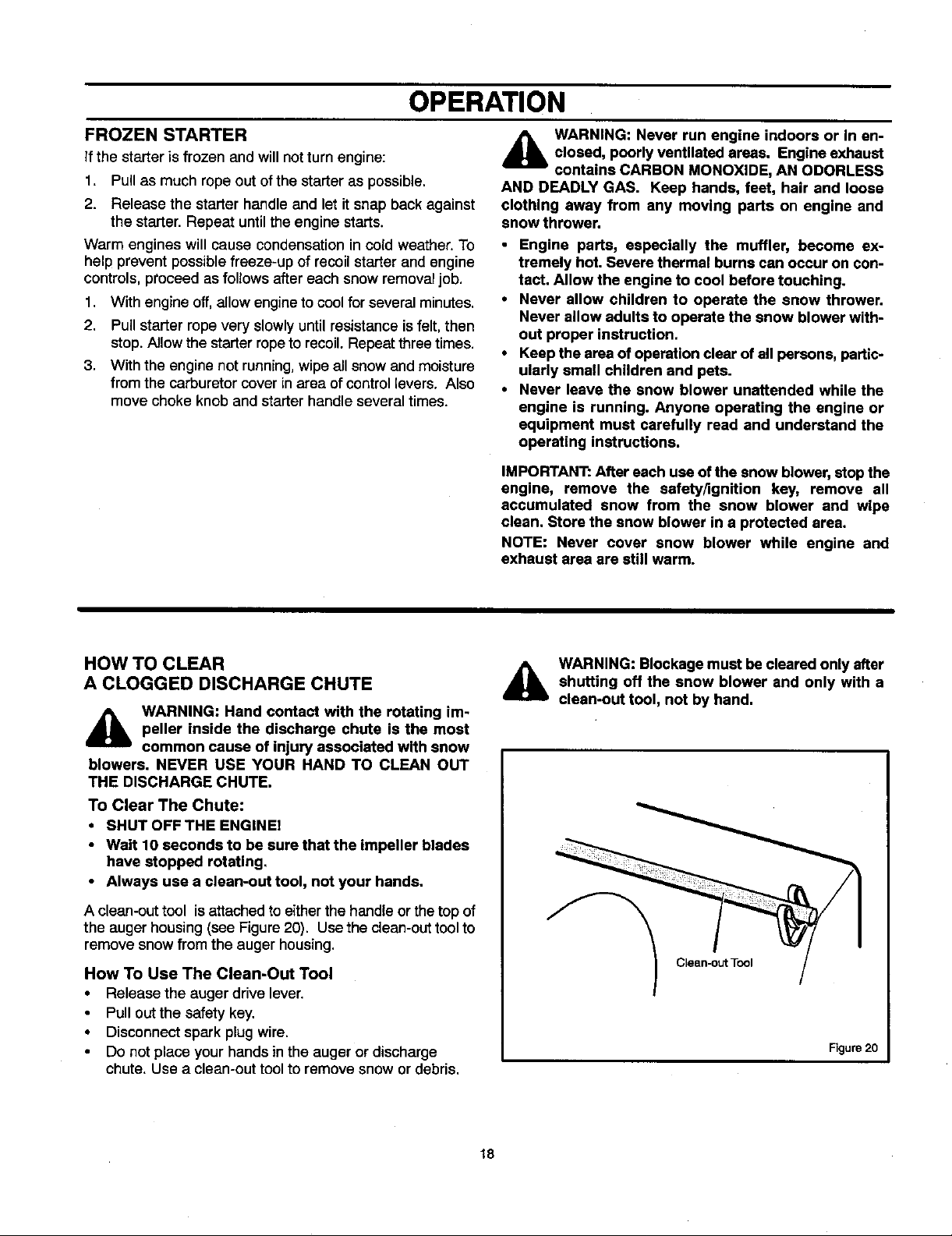
HOW TO CLEAR
A CLOGGED DISCHARGE CHUTE
4_b WARNING: Hand contact with the rotating im-
blowers. NEVER USE YOUR HAND TO CLEAN OUT
THE DISCHARGE CHUTE.
To Clear The Chute:
• SHUT OFF THE ENGINE!
• Wait 10 seconds to be sure that the impeller blades
• Always use a clean-out tool, not your hands.
A clean-out tool isattached toeither the handle or the top of
the auger housing (see Figure 20). Use the clean-out tool to
remove snow from the auger housing.
How To Use The Clean-Out Tool
• Release the auger drive lever.
• Disconnect spark plug wire.
peller inside the discharge chute is the most
common cause of injury associated with snow
have stopped rotating.
Pullcut the safety key.
Do not place your handsin the auger or discharge
chute. Use a clean-out tool to remove snowor debris.
WARNING: Blockage must be cleared only after
,a,
shutting off the snow blower and only with a
clean-out tool, not by hand.
/_ Clean-out Tool
Figure 20
18
Page 19
OPERATION
OPERATING TIPS
1,
Most efficient snowblowingis accomplished when snow
isremoved immediately after it falls.
2.
For complete snow removal, slightly overlap each swath
previously taken.
3.
Snow should be discharged downwind whenever pos-
sible. 8.
4.
For normal usage, set the skids one-eighth inch (3 mm)
below the scraper bar, For extremely hard-packed snow
surfaces, the skids may be adjusted upward to insure
cleaning efficiency.
5.
On gravel or crushed rock surfaces, the skids should be
set at 1-1/4 inch (32 mm) below the scraper bar (see To
Adjust Skid Height, in the Adjustment/Repair section in
this manual). Rocks and gravel must not be picked up
and thrown by the machine.
6,
After the snowblowingjob has been completed, allow the
engine to idle for a few minutes, to melt snow and ice ac-
cumulated on the engine.
7.
Clean the snow thrower thoroughly after each use.
Remove ice and snow accumulation and all debris from
the entire snow thrower, and flush with water Ofpossible)
to remove all salt or other chemicals. Wipe snowthrower
dry.
9,
Before starting snow blower, always inspectaugers and
impeller for ice accumulation and/or debris, which could
result in snow blower damage.
10.
Check oil level before every start. Make sure the oil isat
the FULL mark on the oil fill cap/dipstick.
19
Page 20
SERVICE RECOMMENDATIONS
SERVICE RECOMMENDATIONS
PROCEDURE
]]ghtenallscrewsand
nuts
S
Check Traction Clutch
N
Cable Ad ustment
O
See Cab e Ad ustment)
W
Check Auger clutch Cable
B
\d ustment
See Cab e Ad ustment)
L
O
Adjust Drive Belts
W
Lubricate Chains and
E
Hex Shaft
R
Lubricate Auger Shaft
See Shear Bolt Replace-
ment)
E
Oil, Check
N
Oil, Change
G
I
Check and Clean Spark
Plug
N
E
iReplace Spark Plug .j
FIRST BEFORE EVERY EVERY EVERY EVERY EVERY BEGINNING
2 EACH 8 10 25 50 100 EACH BEFORE
HOUR USE HOURS HOURS HOURS HOURS HOURS SEASON STORAGE
q
q
q
q
q
q
q
q
Clean and InspectSpark
Arrestor
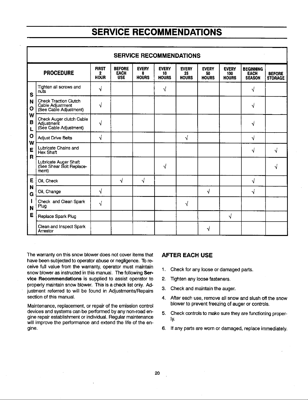
The warranty on thissnow blower does not cover itemsthat
have been subjected to operator abuse or negligence. Tore-
ceive full value from the warranty, operator must maintain
snow blower as instructed inthis manual. The following Ser-
vice Recommendations is supplied to assist operator to
properlymaintain snow blower. This is a check list only. Ad-
justment referred to will be found in Adjustments/Repairs
section of this manual.
Maintenance, replacement, or repair of the emission control
devices and systems can be performed by any non-road en-
gine repair establishment or individual. Regular maintenance
will improve the performance and extend the life of the en-
gine.
AFTER EACH USE
1. Check for any loose or damaged parts.
2. "lighten any loose fasteners.
3. Check and maintain the auger.
4. After each use, remove all snow and slush offthe snow
blower to prevent freezing of auger or controls.
5. Check controls to make sure they arefunctioningproper-
ly.
6. If any parts are worn or damaged, replace immediately.
2O
Page 21
CUSTOMER RESPONSIBILITIES
Some adjustments will need to be made periodically to
properly maintain your snow blower.
All adjustments in ADJUSTMENTS/REPAIRS section of this
manual should be checked at least once each season.
SNOW BLOWER
The following adjustment should be performed more than
once each season.
Auger and Traction Drive Belts shouldbe adjustedafterthe
first2 to 4 hoursof use, again about mid-season and twice
each season thereafter(See ToAdjustBeltsparagraphinthe
Adjustment/Repairsestion).
AS REQUIRED
Auger Gear Box
The auger gear box islubricated atthe factory and shouldnot
require additional lubrication.
If fQrsome reason the lubricant should leak out, or ifthe auger
gear box has been serviced, add Lubriplate GR132 Grease
or equivalent. Maximum 3-1/4 ounces, (92 grams) should be
used.
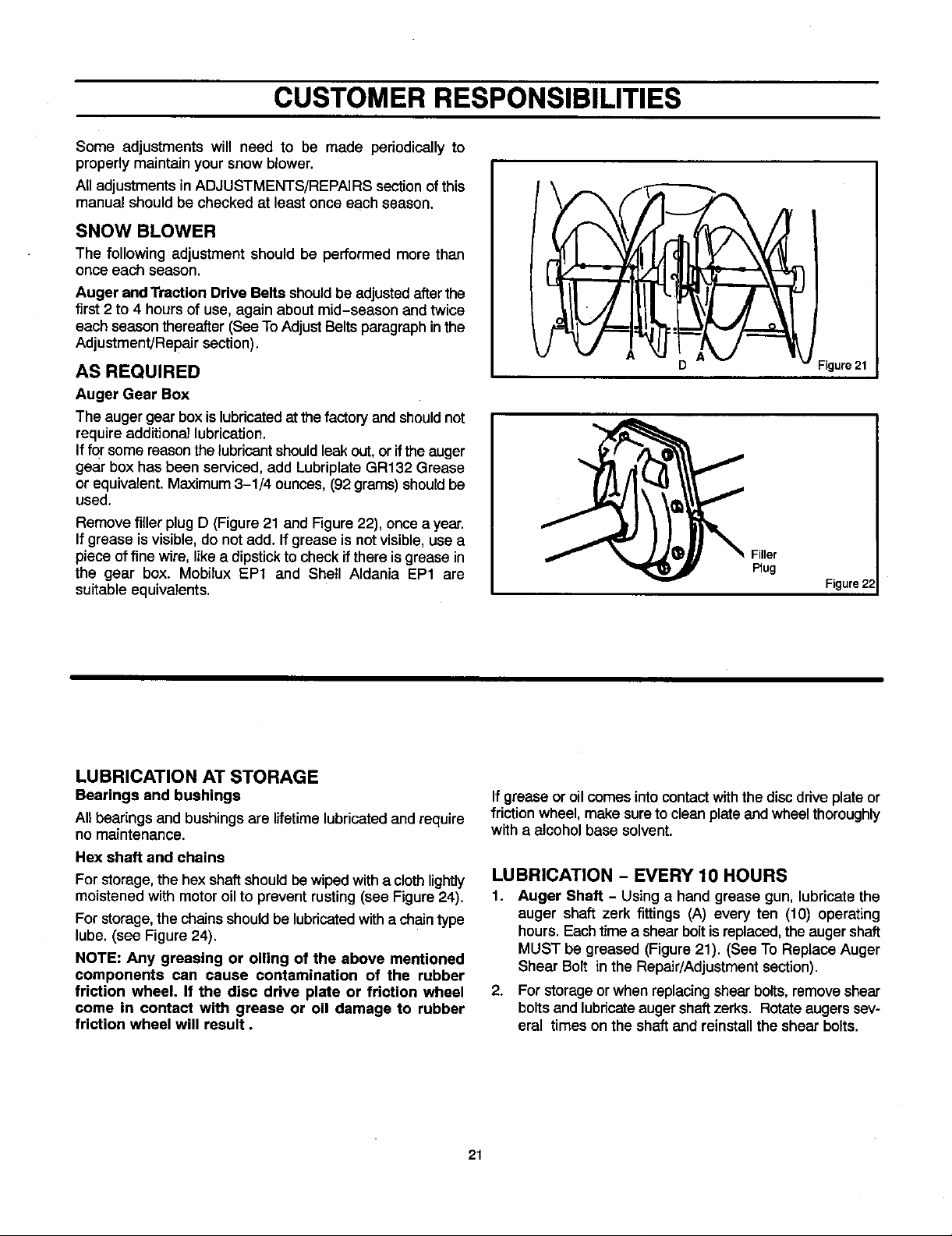
Remove filler plug D (Figure 21 and Figure 22), once a year.
If grease is visible, do not add. If grease is not visible, use a
piece of fine wire, like a dipstick tocheck if there is grease in
the gear box. Mobilux EP1 and Shell Aldania EP1 are
suitable equivalents.
Filler
Plug
Figure 22
LUBRICATION AT STORAGE
Bearings and bushings
All bearings and bushingsare lifetimelubricatedand require
no maintenance.
Hex shaft and chains
For storage, the hex shaftshouldbe wiped witha clothlightly
moistened with motor oil to prevent rusting (see Figure 24).
For storage, the chains should be lubricated witha chain type
lube. (see Figure 24).
NOTE: Any greasing or oiling of the above mentioned
components can cause contamination of the rubber
friction wheel. If the disc drive plate or friction wheel
come in contact with grease or oil damage to rubber
friction wheel will result.
If grease or oil comes into contact withthe disc drive plate or
friction wheel, make sure to clean plate and wheel thoroughly
with a alcohol base solvent.
LUBRICATION - EVERY 10 HOURS
1. Auger Shaft - Usinga hand grease gun, lubricatethe
auger shaft zerk fittings (A) every ten (10) operating
hours. Each time a shear bolt is replaced, the auger shaft
MUST be greased (Figure 21). (See To Replace Auger
Shear Bolt in the Repair/Adjustment section).
2. For storageor when replacing shear bolts, removeshear
bolts and lubricate auger shaft zerks. Rotate augers sev-
eral times on the shaft and reinstall the shear bolts.
21
Page 22

CUSTOMER RESPONSIBILITIES
LUBRICATION - EVERY 25 HOURS
Chute Rotation Gear
Lubricatethe chute rotation gear withautomotivetype oil,
(see Figure 23).
Figure 22
Chains
1. Position speed selector lever infirst (1) forward gear.
2. Stand the snow blower up on the auger housing end.
NOTE: When the crank case if filled with oil, do not
leave the snow blower standing up on the auger
housing for an extended period of time,
3. Remove the bottom panel.
4. Lubricate the chains witha chain type lubricant.
5. Wipe the hexshaft and sprockets with5W30 motoroil,
NOTE: Clean all excess grease or oil found on the
rubber friction wheel or the disc drive plate.
CAUTION: Do not allow grease or oil to contact the
rubber friction wheel or the disc drive plate,
6. Installthe bottom panel,
22
contact with grease or oil
ge to rubber friction wheel
will result,
If grease or oilcome in contact with
the disc drive plate orfriction wheel,
make sure to cJeanthe plate and
wheel thoroughlywith a alcohol base
solvent.
t in
"!
Figure 24
Page 23

CUSTOMER RESPONSIBILITIES
ENGINE
POWER RATINGS
The power ratingsfor an individualengine model are initially
developed by starting with SAE (Society of Automotive
Engineers) code J1940 (Small Engine Power & Torque
Rating Procedure) (Revision 2002-05). Given both the wide
array of products on which our engines are placed, and the
variety of environmental issues applicable to operating the
equipment, it may be thatthe engine you have purchased will
not develop the rated horsepower when used in a piece of
power equipment (actual "on-site" power). This difference is
due to a variety of factors including, but not limited to, the
following: differences in altitude, temperature, barometric
pressure, humidity, fuel, engine lubrication, maximum
governed engine speed, individual engine to engine
variability, design of the particular piece of power equipment,
the manner in which the engine is operated, engine run-in to
reduce friction and clean out of combustion chambers,
adjustments to the valves and carburetor, and other factors.
The power ratings may also be adjusted based on
comparisons to other similar engines utilized in similar
applications, and will therefore not necessarily match the
values derived using the foregoing codes.
TEMPERATURE TYPE OF OIL
0°F (-18 ° C) and above S.A.E. 5W30
0°F (-18 ° C) and below synthetic 5W30
SAE VISCOSITY GRADES
°F 20 0 20 32 40
°C -30 -20 -10 0 10
II I II s s
i l • l l
Oil Fill Cap/Dipstick _ _ b
F 'LL
Check Crankcase Oil Level before starting engine andafter
each 8 hours of continuous use (see Figure 25). Add the
recommendedmotoroil as required.
NOTE: Overfilling the engine can affect performance.
Tighten the oil fill cap securely to prevent leakage.
Change Oil every 50 hoursofoperation or at least once a
year, even ifthe snow blower is notused forfiftyhours_ Use
a clean, highqualitydetergentoil. Fillthe crankcase to FULL
line on dipstick(see Figure25). Be sure originalcontaineris
marked: A.P.I. service"SF" or higher.Do notuseSAE10W40
oil (as it may notprovideproper lubrication).See Chart for oil
recommendations.
To Drain Oil - Positionsnow blower sothatthe oildrain plug
is lowest point on engine. When the engine is warm, remove
oil drain plug and oil fill cap and drain oil into a suitable
container (Figure 26).
Replace oil drain plug andtighten securely. Refill crank case
with the recommended motor oil.
NOTE: OII level must be at FULL mark. -,uC=*ure
Oil Fillcap/Dipstick
Figure 26
25
23
Page 24

ADJUSTMENT/REPAIR
_lb WARNING: Always turn unit off, remove igni-
AUGER HOUSING HEIGHT ADJUSTMENT
TO ADJUST SCRAPER BAR
After considerable use, the metal scraper bar will have a
definite wear pattern. The scraper bar in conjunction with the
skids should always be adjusted to allow one-eighth of an
inch (3 mm) between the scraper bar and the sidewalk or
area to be cleaned.
To adjust the scraper bar, proceed as follows:
1. Position the snow blower on a levelsurface.
2. Loosen the carriagebolts and nuts securing the scraper
3. Adjust the scraper bar to the proper position. Tighten the
4. For extended operation, the scraper bar may be re-
TO ADJUST SKID HEIGHT
This snow blower is equipped with two height adjust skids,
secured to the outside of the auger housing. These elevate
the front of the snow blower.
When removing snow from a hard surface area such as a
paved driveway or walk, adjust the skids upto bring the front
of the snow blower down.
When removing snow from rock or uneven construction,
raise the front of the snow blower by moving the skids down.
This will help to prevent rocks and other debris from being
picked up and thrown by the augers.
tion key and disconnect the spark plugwire be-
fore making any repairs or adjustments.
bar to the auger housing.
carriage bolts and nuts, insuring that the scraper bar is
parallel with the working surface.
versed. If the scraper bar must be replaced because of
wear, remove the carriage bolts and nuts and install a
new scraper bar.
To adjust skids, proceed as follows:
1. Place a block(equalto heightfrom grounddesired) un-
der scraper bar near butnot under skid.
2. Loosen skid mounting nuts (Figure 27) and push the skid
down until it touches the ground. Retightsn mounting
nuts.
3. Set skid on other side at same height.
NOTE: Make sure that snow blower is sat at same height
on both sides.
,_ WARNING: Be certain to maintain proper
debris, if struck by the impeller, may be thrown with
sufficient force to cause personal injury, property dam-
age or damage to the snow blower.
ground clearance for your particular area to be
cleared. Objects such as gravel, rocks or other
Height Adjust Skid
Skid MountingNuts
Figure 27
24
Page 25

ADJUSTMENT/REPAIR
HOW TO REMOVE THE SNOW HOOD
To access the sparkplug, the snow hoodmustbe removed
as follows:
1. Remove the chokecontrol knob (see Figure 28).
2. Remove the safety key.
3. Remove the mounting screws (see Figure 29).
4. Slowlyremovethe snowhood.Make surethatthe prim-
er button hose and the ignition wire are not discon-
nected.
5. The spark plug can now be accessed.
6. To installthe snow hood, firstmake surethat the primer
buttonhose andthe ignitionwire are connected.
7. Mountthe snow hoodto the engineand secure withthe
mountingscrews (see Figure29).
8. Connect the chokecontrol knobwith the'choke shaft on
the carburetor (seeFigure 30 and Figure 31). Make sure
the choke control knob is properly installed, if the choke
control knob is not installed correctly, the choke will not
operate.
Mounting Screws
Snow Hood
Spark
Plug
Hose
Figure 29
Choke Control Knob
9. In_allthe safety key.
Choke Control
Knob
Choke Shaft Figure 30
Figure 28
Carburetor Figure 31
25
Page 26

ADJ USTMENT/REPAIR
BELT ADJUSTMENT
Traction Drive Belt
The tractiondrive belt has constant springpressure anddoes
not require an adjustment. Ifthe traction drive belt is slipping,
replace the belt. See "How To Replace The Belts" in the
Maintenance section.
Auger Drive Belt
If your snowthrower will not discharge snow, check the
control cable adjustment. If it is correct, then check the
condition of the auger drive belt. If it is damaged or loose,
replace it (see Belt Replacement in this section of the
manual),
1. Disconnect spark plug wire.
2. Remove screw from belt cover. Remove belt cover
(see Figure 32).
3. Loosen nut on auger idler pulley and move auger idler
pulley towards belt about 1/8 inch (3 mm) (see
Figure 36).
4. Tighten nut.
5. Have someone engage auger drive clutch. Check ten-
sion on belt (opposite idler pulley). Belt should deflect
about 1/2 inch (12.5 mm) with moderate pressure
Figure 33). Youmay have to move idler pulley more than
once to obtain the correct tension.
Auger
Drive
( -_'J_- p_ Engine
k.j; o Po,ey
.....3. ;,\ 1/2 inch
Idler"-"w"V _w_ _'_f" _'A Deflection
Pulley /A/_ ;A
6. Reinstall belt cover.
7. Whenever belts are adjusted orreplaced, the cables will
need to be adjusted. (See Cable Adjustment in this sec-
tion of the manual).
8. Attach the spark plug wire.
Engaged _
Pulley
\-÷-/--,m.r
Figure 33
26
Page 27

HOW TO REPLACE THE BELTS
ADJUSTM ENT/RI=PAIR
The drive belts are of special constructionand must be
replaced with original factory replacement belts available
from your nearest authorized service center.
Some steps require the assistance of a second person.
How To Remove the Auger Drive Belt
Ifthe augerdrive belt isdamaged, the snowthrower willnot
discharge snow. Replace the damaged belt as follows.
1. Disconnect the spark plug wire.
2. Loosen the bolts on each side of the bottom panel (see
Figure 34).
3. Remove the bottom panel.
4. Remove screw from belt cover. Remove the belt cover
(see Figure 32).
5. Loosen the belt guide. Pullthe belt guide away from the
auger drive pulley (see Figure 36),
6. Pull the idler pulley away from the auger drive belt and
slip the auger drive belt off of the idler pulley.
7. Remove the auger drive belt from theengine pulley. To
remove the auger drive belt, the engine pulley may
have to be partially rotated,
8. Remove the top four bolts that hold together the auger
housing and the motor box. Loosen the.bottom two
bolts, The auger housing and the motor box can now
be split apart for removal of the belt (see Figure 35).
9. Remove the old auger drive belt from the auger drive
pulley. Replace the auger drive belt with an original
factory replacement belt available from an authorized
service center (see Figure 36).
16. Install the belt cover. Tighten screw (See Figure 32).
17. Check theadjustmentofthe cables.See "How To Check
And Adjust The Cables" inthe Maintenancesection,
18. Installthe bottom panel (see Figure 34).
19. Tightenthe bolts on each side of the bottom panel.
20. Connect the sparkplug wire.
Bolt
Bottom Panel
Auger Housing
Figure 34
10. Install the new auger drive belt onto the auger drive
pulley.
NOTE: To assemble the auger housing to the mo-
tor box, have someone hold the auger clutch lever
in the ENGAGED position. This will move the idler
arm and pulley enough to allow the auger drive
pulley to move back into position,
11. Assemble theauger housing to the motor box with the
four bolts thatwere removedin step 8, Tightenthe bot-
tom two bolts.
12. Install the auger drive belt onto the engine pulley.
13. Slip the auger drive belt underthe idler pulley.
14. Adjust theauger drive belt. See "HowToAdjust The Au-
ger Drive Belt" inthe Maintenancesection.
15. Adjust the belt guide. See "How To Adjust The Belt
Guide" inthe Maintenance section,
27
Motor Box
Bolts
Auger
Housing
Figure 35
Page 28

Swing PlateAxle Rod
ADJUSTMENT/REPAIR
Belt Guide
Auger Drive Pulley
Auger Drive Belt
Traction Drive Spring
Traction DriveBelt
Traction Drive Pulley
Engine Pulley
Figure 36
28
Page 29

ADJ USTM ENT/R EPAIR
How To Remove the Traction Drive Belt
If the snow throwerwillnot move forward, checkthe traction
drive belt for wear or damage. If the traction drive belt isworn
11. Install andadjust the auger drive belt. See =HowToRe-
moveThe Auger Drive Belt"inthe Maintenance section.
or damaged, replace the belt as follows.
1. Disconnect the spark plug wire.
12. Adjust the belt guide. See "How To Adjust The Belt
Guide" in the Maintenance section.
2. Remove the auger drive belt. See "How To RemoveThe
Auger Drive Belt" in the Maintenance section.
13. Install the bottom panel (see Figure 34).
3. Remove the e-ring from one end of the swing plate 14. Tighten the bolts on each side ofthe bottom panel.
axle rod. Remove the swing plate axle rod to allow the
the swingplate to pivotforward (see Figure36). 15. Installthe belt cover. Tighten screw (see Figure32),
4.
Remove the traction drive spring.
5.
Remove the old traction drive belt from the traction
16. Check the adjustment ofthe cables. See "How To Check
And Adjust The Cables" inthe Maintenance section.
drive pulley and from the engine pulley. Replace the
traction drive belt withan originalfactory replacement
17. Connect the spark plug wire.
belt available from an authorized servicecenter.
6.
Install the new traction drive belt onto the traction
drive pulley and ontoengine pulley.
7,
Make sure the traction drive idler pulley is properly
aligned withthe traction drive belt.
t
8. Attach the traction drive spring.
9. Installthe swing plate axle rod and secure withthe e-
ring removed earlier.
10. The bottom ofthe swing plate must be positionedbe-
tween the alignment tabs. Make surethe swing plate
is properlysecured (seeFigure 37).
NOTE: If the drive will not engage after the traction
drive belt has been replaced, then check to make
sure that the swing plate is positioned between the
alignment tabs.
29
I
AJignment Tabs
Figure 37
Page 30

BELT GUIDE ADJUSTMENT
1. Remove spark plug wire.
ADJUSTMENT/REPAIR
2. Have someone engage auger drive.
3. Measure the distance between the belt guide and belt.
The distance should be 1/8 inch (3.175 mm) for guide.
See Figure 38.
4, If adjustment is necessary, loosen belt guide mounting
bolt. Move belt guide to the correct position. Tighten
mounting bolt.
5. Reinstall belt cover.
6. Reconnect spark plug wire.
HOW TO CHECK AND ADJUST THE CABLES
Tl_e cables are adjusted at the factory and no adjustment
should be necessary, tf the cables have become stretched
or are sagging adjustment will be necessary.
Whenever belts are adjusted or replaced, the cables will
need to be adjusted.
To check for correct adjustment, unhook "Z" fitting at
clutch lever (see Figure 39).
_- -'_O// BeltGuide
i
Figure 38
"Z"Fitting Control lever
forwardposition
(justcontacting
plastic bumper)
when checking
cable length.
must be in full
1. Move clutch lever to the full forward position (just con-
tacting plastic bumper). Holding cable tight, note posi-
tion of fitting to hole in clutch lever,
2. The center ofthe "Z" fitting should be between the centre
and top of the hole in the clutch lever. Adjust either the
auger drive cable or the traction drive cable as follows.
Auger Drive Cable Adjustment
_k WARNING: Drain the gasoline outdoors, away
1,
2,
3,
from fire or flame.
Remove the gas from the gas tank. Stand the snow
thrower up on the front end of the auger housing.
Push cable through spring to expose the threaded por-
tion of the cable (see Figure 40).
Hold square end of threaded portion with pliers and ad-
just locknutin or out until correct adjustment is reached.
Pull cable back through spring and connect cable.
30
Square
End
Plastic
Bumper
Figure 39
x,,
Cable
Spring
o
Locknut
Figure 40
Page 31

Traction Drive Cable Adjustment
ADJUSTMENT/REPAIR
_lb ARNING: Drain the gasoline outdoors, away
1. Remove the gas from the gas tank. Stand the snow
2. Loosenthe bolts on each side ofthe bottom panel (see
3. Remove the bottom panel.
4. Disconnect the "Z" fitting from the drive lever (see
5. Slide the cable boot offthe cable adjustment bracket
6. Push the bottom of the traction drive cable throughthe
7. Remove the "Z" hook from the cable adjustment
from fire or flame.
thrower up on the front end of the auger housing.
Figure 41).
Figure 39),
(see Figure 42).
cable adjustment bracket untilthe"Z" hook can bere-
moved.
bracket. Move the "Z '° hook down to the next adjust-
ment hole.
8. Pullthe traction drive cable upthroughthe cable ad-
justment bracket.
9, Putthe cable boot overthe cable adjustment bracket.
10, Install the "Z" hook to the traction drive lever (see
Figure39).
11. To check the adjustment, depress the drive lever and
check the length of the drive spring (see Figure 43). In
correct adjustment, the length of the drive spring is
minimum 3 inches (76 mm.)
maximum 3-3/8 inches (85 mm.),
12. Install the bottom panel (see Figure 41).
13. "nghtenthe bolts oneach side ofthe bottom panel.
31
Page 32

ADJUSTMENT/REPAIR
HOW TO ADJUST OR REPLACE
THE FRICTION WHEEL
How To Check The Friction Wheel
If the snow thrower willnot move forward, checkthe traction
drive belt, the traction drive cable orthe friction wheel. If the
friction wheel is worn or damaged, it must be replaced. See
"How To Replace the Friction Wheel" in this section. If the
friction wheel is not worn or damaged, check as follows.
1. Remove the gas from the gas tank. Stand the snow
thrower up on the front end of the auger housing (see
Figure 44).
_Jll= WARNING: Drain the gasoline outdoors, away
2. Disconnect the spark plug wire.
3. Loosen the bolts oneach side ofthe bottom panel (see
4. Remove the bottom panel.
from fire or flame.
Figure44).
5. Tightenthe jam nut.
6. Installthe bottom panel (see Figure 44).
7. Tighten the bolts on each side of the bottom panel,
Bolt
II
5. Position the shift speed lever in the lowest forward
speed.
6.
Note the position ofthe friction wheel (see Figure 45).
The correctdistance "A" from the rightside ofthe fric-
tion wheel to the outside ofthe motorbox is as follows:
Tire Size Distance "A"
12 and 13 inch 4-1/8" (10.5 cm.)
16 inch 4-5/16" (10.95 cm.)
Ifthe friction wheel isnot inthe correct position,adjust
as follows.
How To Adjust The Friction Wheel
1,
Position the shift speed lever in the lowest forward
speed.
2,
Loosen hex jam nut on speed select rod. Remove ball
joint from shifter bracket (see Figure46).
3.
Move the friction wheel against tothe correctposition
(see Figure 45).
Figure 45
Rod
\
Adap_r
4.
Turn the adaptor untilthe ball joint is aligned withthe
mounting hole in the shifter rod (see Figure 46). When
aligned, attach the ball joint to the shifter rod.
er Rod _1
Figure 46
32
Page 33

ADJUSTMENT/REPAIR
How To Replace The Friction Wheel
Ifthe friction wheelisworn or damaged, the snowthrower will
not move forward. The friction wheel must be replaced as
follows.
1. Remove the gas from the gas tank. Stand the snow
thrower up on the front end of the auger housing (4),
(see Figure 44).
_lb ARNING: Drain the gasoline outdoors, away
from fire or flame.
2. Disconnect the spark plug wire.
3. Remove the fasteners that secure the left wheal. Re-
move the left wheel from the axle (see Figure 47)
4. Loosen the bolts on each side of the bottom panel.
5. Remove the bottom panel.
Axle Bort
8,
Remove the fourbolts that holdthe bearings on each
side of the hex shaft (see Figure49).
9.
Remove the hex shaft and bearings.
NOTE: Take special note of the position of the
washers on the hex shaft.
_dJ
Panel
Bolt
Wheel Figure 47
6. Remove the fastenersthat securethe drive sprocket to
the axle (see Figure48).
7. Remove the right wheel, axle, and drive sprocket.
t
49
33
Page 34

ADJUSTMENT/REPAIR
10. Remove thethree fasteners that holdthe friction wheel
to the hub (see Figure 50).
11. Remove the friction wheel from the hub. Slip the fric-
tion wheel offthe hex shaft.
12. Assemble the new friction wheel onto hub withthe fas-
teners removed earlier.
Fasteners
Hex Shaft
Friction
Hub Wheel
\
Washer
\
Washer
15.
Installthe right wheel, axle, and drive sprocket withthe
_.,._ Washer
fasteners removed earlier. Install the chain onto the
drive sprocket (see Figure48).
Figure 51
16.
Check the adjustment of the friction wheel. See "HowTo
Fasteners
Figure 50
Adjust The Friction Wheel" in this section.
17.
Make sure the friction wheel and the disc drive plate are
free from grease or oil.
13. Install the hex shaft and bearings with the four bolts re-
18. Install the bottom panel (see Figure 47).
moved earlier (see Figure51).
19. _ghtan the bolts on each side ofthe bottom panel.
Make sure the washers are properly installed in the
original position. Also, make sure the two washers
are properly aligned with the actuator arms.
20. Installthe left wheel to the axle with the fasteners re-
moved earlier.
14. Make sure the hex shaft turnsfreely. 21. Connect the spark plug wire.
34
Page 35

ADJUSTMENT/REPAIR
AUGER SHEAR BOLT REPLACEMENT
The augers are secured to the auger shaftwith specialbolts
that are designed to break if an object becomes lodged inthe
auger housing. Use of a harderbolt will reduce the protection
provided by the shear bolt. To replace a broken shear bolt,
proceed as follows:
_lb WARNING: To insure safety and performance
levels, only original replacement shear bolts
should be used.
1. Stop engine, disengage all controls, disconnect the
spark plug lead wire, and insure all moving parts have
stopped.
2. Lubricate the auger shaft zerk fittings (see Lubrication
Points in the Maintenance section of this manual).
3,
Align the holein theauger with the holein the auger shaft.
Install new shear bolt, spacer and Iocknut found in the
toolbox located on the belt cover (See Figure 52). "l]ght-
en with the shear boltwrench.
NOTE: For the operator's convlence, the shear bolt
wrenches are located in the toolbox.
NOTE: The spacer fits into the larger hole in the auger
tube.
Shear Bolt Wrench
Shear Pin _
LF _ Spacer
Locknut
Figure 52
SPARK PLUG ADJUSTMENT (SEE FIGURE 53)
NOTICE: This spark ignition system meets all 6.
requirements of the Canadian Interference-Causing
Equipment Regulations.
Check thespark plug everytwenty-five (25) hours.Replace
the spark plug if the electrodesare pittedor burned, if the
porcelain is cracked, or every 100 hoursof use.
1. Clean spark plug and reset gap periodically.
2. Clean area around spark plug base before removal, to
prevent dirt from entering engine.
3. Replace spark plug if electrodes are pitted or burned or
if porcelain is cracked.
4,
Clean sparkplug by carefully scrapingelectrodes (donot
sandblast or use wire brush).
5.
Be sure spark plug is cleanand free of foreign material.
Check electrodes gap with a wire feeler gauge and reset
gap to 0.030" (0.76 mm) if necessary. Ifa new spark plug
is needed, refer to Engine Repair Parts section of this
manual for proper replacement spark plug.
35
Before installing spark plug, coat threads lightly with
graphite grease to insure easy removal.
7.
"nghten plug firmly into engine. If torque wrench is avail-
able, torque plug to 18-23 ft-lbs.
Figure 53
Page 36

STORAGE
OFF SEASON STORAGE
_lb ARNING: Never store engine with fuel in tank
flame, spark or pilot light as on a furnace, water heater,
clothes dryer, etc.
Handle gasoline carefully. It is highly flammable and
careless use could result Inserious fire damageto your
person and/or property.
Drain fuel into approved containers outdoors, away
from open flame.
If the snow blower is to be stored for thirty (30) days or more
at the end of the snow season, the following steps are
recommended to prepare your snow blower for storage.
NOTE: Gasoline must be removed or treated to prevent
gum deposits from forming in the tank, filter, hose, and
carburetor during storage.
1,
4_lb WARNING" Drain gasoline outdoors, away fromfire or flame.
indoors or in enclosed, poorly ventilated enclo-
sures, where fuel fumes may reach an open
To remove gasoline, run engine until tank is empty and
engine stops.Then drain remaining gasoline from carbu-
retor by pressing upward on bowl drain located on the
bottom of carburetor (see Figure 54).
4. Thoroughly clean the snow blower.
5. Lubricate all lubricationpoints (see Lubrication, see Cus-
tomer Responsibilities).
5. Insure that all nuts, bolts, and screws are securely fas-
tened. Inspect all visible moving parts for damage,
breakage, and wear. Replace if necessary.
7. Touch up all rusted orchipped paint surfaces; sand lightly
before painting.
8. Cover the bare metal parts of the blower housing auger,
and the impeller with rust preventative.
9. If possible, store your snow blower indoors and cover it
to give protection from dust and dirt.
10. Store ina clean and dry area, but NOT near a stove, fur-
nace orwater heater which uses apilot light or any device
that can create aspark.
11. If the machine must be stored outdoors, block up the
snow blower and insure the entire machine is off the
ground. Cover the snow blower with a heavy tarpaulin.
If you do not want to remove gasoline use the fuel stabilizer
supplied with unit. Add fuel stabilizer (follow instructions on
fuel stabilizer package) to any gasoline left in the tank to
minimize gum deposits and acids. If the tank is almost empty,
mix stabilizer with fresh gasoline in a separate container and
add some to the tank. ALWAYS FOLLOW INSTRUCTIONS
ON STABILIZER CONTAINER. THEN RUN ENGINE AT
LEAST 10 MINUTES AFTER STABILIZER IS ADDED TO
ALLOW MIXTURE TO REACH CARBURETOR. STORE
SNOW BLOWER IN SAFE PLACE.
2. You can help keep your engine ingood operating condi-
tion by changing oil before storage.
3. Remove the spark plugand pour about 15 ml (1/2 oz) of
engine oil into the cylinder. Replace the spark plug and
crank slowly to distribute the oil.
Bowl Drain
Figure 54
36
Page 37

TROUBLE SHOOTING CHART
PROBLEM LOOK FOR REMEDY
Difficult starting Defective spark plug. Replace defectivespark ptug.
Engine runs erratically Blocked fuel line. Clean fuel line.
Emptygas tank. Check fuel supply,
Stale gasoline. Addfresh gasolinewithfuel stabilizer.
Water or dirtin fuel system. Remove carburetorbowlto drainfuel tank. Refill
withfresh fuel. CAUTION: Do not remove
carburetor bowl when the engine is hot.
' Engine stalls Unit running on CHOKE. Set choke leverto RUN position.
Loss of power Gas cap vent hole is plugged. Remove ice and snowfrom cap. Be surevent
Excessive vibration Loose parts or damaged impeller, Stop engine immediatelyand removespark plug
Unit fails to propel Drive belt loose or damaged. Replace drive belt. Refer to Drive Belt
itself Replacement inAdjustments/Repairs sectionof
hole isclear.
wire. Tighten all bolts and make all necessary
repairs. If vibration continues, have the unit
serviced by a competent repairman.
this manual.
Incorrectadjustmentoftractiondrive Adjust tractiondrive cable. Refer to Cable
cable. Adjustment inAdjustments/Repairs sectionof
Worn or damaged frictiondisc. Replace friction disc. Refer to Friction Wheel
Unit fails to discharge Auger drive belt looseor damaged. Replace oradjustauger drivebelt, Refer to Drive
snow Belt Replacement and Drive Belt Adjustment in
Auger controlcable notadjusted Adjust auger controlcable. Refer to Cable
correctly. Adjustment inAdjustments/Repairs sectionof
Broken shear bolt. Replace shear bolt. Refer to Auger Shear Bolt
Discharge chuteclogged. Stop engine immediatelyand disconnect spark
Foreign object lodged in auger. Stop engineimmediatelyand disconnectspark
this manual.
Replacement inAdjustments/Repairs sectionof
this manual.
Adjuetments/Repairs sectionofthis manual,
this manual.
Replacement inAdjustments/Repairs sectionof
this manual.
plugwire. Refer to the first Warning in Snow
blower Operation inOperation sectionof this
manual. Clean dischargechuteand inside of
auger housing.
plug wire. Refer to the third Warning in Snow
blower Operation in Operation sectionof this
manual. Remove object from auger.
Identifying Your Snow blower
Your new Snow blower has two (2) identifying numbers: (1) unitmodel number: (2) unit serial number. The two preceding
numbers are required to insure that the proper replacement parts are obtained when required, if you have any questions
concerning parts, service, or technical data, contact your nearest Sears Service Department.
For complete warranty information refer to the warranty in the Owner's Information section of this manual.
37
Page 38

CRAFTSMAN 30" SNOW BLOWER C950524312A REPAIRPARTS
CRAFTSMAN 30" CHASSE NEIGE C950524312A PIECESDERECHANGE
ENGINE / MOTEUR
25-2
5
25-3
25-2
\
\
28
16
\
I
17
\
12
20/
22
24 14 J
/ 15
25-1
4
25-4
6
/
11
18
8
/
\
/
9
Ref. Drive Page
3
Ref. Auger Housing Page
38
Page 39

CRAFTSMAN 30" SNOW BLOWER C950524312A REPAIRPARTS
CRAFTSMAN 30" CHASSE NEIGE C950524312A PIECESDERECHANGE
ENGINE / MOTEUR
Key No.
NO8ur le Part No,
sch6ma N° de piTce Description Description
1 6219 CORD, STARTER CORDE DU DEMARREUR
2 ..... ENGINE MOTEUR
3 002x97 BOLT, CARRIAGE 5/16-18 BOULON, PO. 5/16-18
4 028x76 RETAINER, PUSH RONDELLE DE RETENUE
5 710026 NUT 5/16-18 ECROU 5/16-18
6 1501109 PULLEY, ENGINE POULIE MOTRICE DOUBLE
7 17x170 WASHER RONDELLE
8 71063 WASHER RONDELLE-FREIN DI .38
9 001x2O SCREW, 3/8-24Xl.00 VIS, 3/8-24XI.00
10 579932 BELT, V 3L COURROIE TRAPEZOID. V 3L
11 585415 BELT, V 4L COURROIE TRAPEZOID. V 4L
12 1501112 YZ BRACKET ASSEMBLY, IDLER PATFE DE FIXATION, POULIB LIBRE
13 1501065 BUSHING, IDLER BRACKET ENTRETOISE, FIXATION DE POULIE LISRE
14 71060 WASHER RONDELLE
15 710097 SCREW5/16-24XO.75 V[S 5/18-24 X 0.75
16 53704 SPRING RESSORT
17 1502120 PULLEY, IDLER PULLIE LIBRE
18 590 NUT, JAM 3/8-16 CONTRE-ECROU 3/8-16
2O 15012O1 GUIDE, ROD BELT GUIDE DE COURROIE
22 71060 WASHER, SPTLK .31X.58X.08 RONDELLE-FREIN .31X.58X.08
24 710097 SCREW, 5/18-24X 0,75 VIS 5/16-24X 0.75
25 FRAME ASSEMBLY CHASSIS DE MONTAGE, MOTEUR
25-1 1501062E737 PLATE, ENGINE MOUNT PLAQUE DE MONTAGE, MOTEUR
25-2 310169 SCREW 1/4-20 X .63 VIS 1/4-20 X .63
25-3 25x02O SCREW 5/16-18 X .50 VIS 5/16-18 X .50
25-4 1501040E737 FRAME, MOTOR BOX SUPPORT DE MONTAGE, MOTEUR
26 282045 KEY, IGNITION CLE
27 226462 DEFLECTOR, MUFFLER DI_FLECTEUR DE SILENCIEUX
28 810140 SCREW VIS
39
Page 40

CRAFTSMAN 30" SNOW BLOWER C950524312A REPAIRPARTS
CRAFTSMAN 30" CHASSE NEIGE C950524312A PII=CESDERECHANGE
FRAME / BATI
1(36 160
/
111
Ref. Engine Page _ q__
I,
162
91
122_
123 /
91
Ref. Auger
Housing Page
Ref. Drive Page
168
/
103
149 107
4O
Page 41

CRAFTSMAN 30" SNOW BLOWER C950524312A REPAIRPARTS
CRAFTSMAN 30" CHASSE NEIGE C950524312A PIECESDE RECHANGE
FRAME / BATI
Key No.
NO6urle Part No.
sch6ma N° de piece Description
90 1501055E701 COVER, BOTTOM
Description
PANNEAU INFERIEUR
91 310169 SCREW, 1/4-20X .63
103 1501782 YZ IDLER ASSEMBLY, AUGER
105 711682 PIN, HAIR .38DIAX1.64LG
106 761761 PIN, CLEVIS 3/15" DIA
107 155x159 SPRING, TENSION
108 761675 YZ ASSY., SPRING ATTACH
110 585781 BOLT, 3/8-15X1.25 CARR.
111 711617 WASHER, FLAT
122 25x020 SCREW, TAP 5/16-18 X .50
123 25x021 SCREW, TAP 5/16-18 X .75
148 1502120 PULLEY, IDLER
149 590 NUT 3/8-15
160 1502184 COVER, BELT
162 26x306 SCREW, TAP
VIS 1/4-20X ,63
BRAS DE POULIE LISRE. ENTRAINEMENT DES LAMES
GOUPILLE BETA
GOUPILLE
RESSORT DE TENSION
PATrE DE FIXATION POUR RESSORT
BOULON BLOQUANT 3/8-16Xl.25
RONDELLE PLATE
VIS 5/16-18 X .50
VIS 5/16-18 X .75
PULLIE LIBRE
_CROU 3/8-16
CARTER DES COURROIES
VIS
167 71067 WASHER, FLAT
168 1501200 SPACER, AUGER BRACKET
169 760539 LID, TOOL BOX
RONDELLE PLATE
ENTRETOISE, FIXATION DES LAMES CHASSE-NEIGE
COUVERCLE DE BOITE A OUTILS
41
Page 42

CRAFTSMAN 30" SNOW BLOWER C950524312A REPAIR PARTS
CRAFTSMAN 30" CHASSE NEIGE C950524312A PII=CESDERECHANGE
DRIVE / BATI DE MONTAGE DU MOTEUR
/
/ 236
Ref. Wheel
\
Ref. ShiftYoke Page
204 203 '
\
f _ _-_'_ _ 229
Ref. Frame Page /,,_: _,\
\ \
f. Wheel 200 \
Page
221
223
226
\
I \
/
\
225
227
/
230
\
Wheel Page
220
208 q
238
Ref. Wheel \
Page
207
213
213
/
210\238
215
\
22O
218
\
\
212
213
42
218
217
Page 43

CRAFTSMAN 30" SNOW BLOWER C950524312A REPAIRPARTS
CRAFTSMAN 30" CHASSE NEIGE C950524312A PIECESDE RECHANGE
DRIVE / BATI DE MONTAGE DU MOTEUR
Key No.
NOsur le Part No.
sch6ma N ° de piece Description Description
200 1501092 YZ LF AXLE, SWING PLATE YZ PANNEAU ARTICULE
201 879851 CHAIN, ROLLER #420 xl 9.00 CHAINE A GALETS #420 xl 9,00
203 334183 BEARING AND RETAINER, ASSY ROULEMENT AVEC FIXATION
204 579858 WASHER RONDELLE
206 25x020 SCREEN,TAP 5/16-18x0.5 VIS, 5/15-18xo.5
207 1501238 ASS"(, HEX SHAFT ARBRE HEXAGONAL
208 579868 CHAIN, ROLLER #420 xl 8.00 LG CHAINE A GALETS #420 x18.00 LG
210 337029 BEARING, TRUNION CLUTCH R PALIER
212 1501435 WHEEL, FRICTION DISC ROUE DE FRICTION
213 001X38 BOLT BOULON
215 303008 NUT, KEPS HEX 1/4-20 ECROU 6 PANS 1/4-20
217 579859 RING, RE-TEXT ClRCLIP
218 579858 WASHER RONDELLE
220 334163 BEARING AND RETAINER, ,t_Sy ROULEMENT AVEC FIXATION
221 25x020 SCREW, TAP 5/18-18 x .5 VIS, 5/16-18 x .5
223 15Ol115 ASSY. FRICTION PULLEY POULIE, SYSTEME DE FRICTION
225 1501057 YZ LF PLATE, SWINGING YZ PANNEAU ARTICULE
226 1501158 SPACER, FRICTION PULLEY ENTRETOISE DE POULIE, SYSTEME DE FRICTION
227 15x114 NUT, FLANGE LOCK 3/8-24 ECROU A COLLET 3/8--24
229 11x30 RETAINER, RING ClRCLIP
230 1502105 YZ LF ASSY, SPRING LINK YZ TRINGLE D ATTACHE DES RESSORTS
232 11x30 RETAINER, RING CIRCLIP
234 155x112 SPRING, EXTENSION RESSORT D'EXTENSION
236 1501237 WLD. INTERMED SPROCKET 331/7 PIGNON INTERMEDIAIRE 33T/7
238 71074 WASHER, FLAT RONDELLE PLATE
43
Page 44

CRAFTSMAN 30" SNOW BLOWER C950524312A REPAIRPARTS
CRAFTSMAN 30" CHASSE NEIGE C950524312A PIECESDERECHANGE
AUGER HOUSING / VIS SANS FIN
484
485
480
522
4-91
523
\\
544
540
5OO
511
541
525
493
522
J
523
z \ \
Ref. Gear Case Assy
510
\
525
520
524
44
Page 45

CRAFTSMAN 30" SNOW BLOWER C950524312A REPAIRPARTS
CRAFTSMAN 30" CHASSE NEIGE C950524312A PII CESDERECHANGE
AUGER HOUSING / VIS SANS FIN
Key No.
N° surle Part No.
sch6ma N° de piece Description Description
480 583146 PULLEY, 4L 8.40 OD. POULIE 4L 8,40
482 2001022 KEy, SQUARE 3/16 X3/4 CLAVETTE A SECTION CARREE 3/16 X 3/4
484 15x112 NUT, .50-20 HEXWDFLLK ECROU, 6 PANS ,50-20
485 1501158 SPACER, FRICTION PULLEY ENTRETOISE DE POULIE, SYSTEME DE FRICTION
490 582957 YZ RETAINER, BALL BRNG CAPUCHON DE ROULEMENT A BILLES
491 1501389 BEARING, BALL ROULEMENT A BILLES
493 0Olx92 BOLT, HEX 5/16-18X .50 BOULON 6 PANS5/16-18X .50
499 710026 NUT, 5/16-18 HEXWDFLLK ECROU 6 PANS 5/16-18
500 1501695E737 HOUSING, ASSY CARTER DES LAMES CHASSE-NEIGE
510 760659E701 BLADE, SCRAPER LAME RACLEUSE
511 001x45 BOLT,5/16-18}(0.62 BOULON 5/16-18x0.62
514 710026 NUT, 5/18-18 ECROU 5/18-18
520 760591E701 AUGER, ASSY, LH LAME CHASSE-NEIGE (VIS SANS FIN), GAUCHE
521 760592E701 AUGER, ,aSS'(, RH LAME CHASSE-NEIGE (VIS SANS FIN), DROITE
522 9524 SCREW, 1/4-20)(1,75 VIS 1/4-20Xl .75
523 3943 SPACER, SLEEVE ENTRETOIS E
524 73826 NUT, 1/4-20 ECROU 1/4-20
525 53757 BEARING, FLANGE PALER A BRIDE
527 25x021 SCREW, 5/16-18X .75 VlS 5/16-18)( .75
540 309016E701 SKID, HEIGHT ADJUST PATIN REGLABLE
541 340720 BOLT, 5/16-18 X .75 BOULON 5/16-18 X .75
544 710026 NUT, 5/16-18 ECROU 5/16-18
550 1501576 BRUSH, CLEANOUT OUTIL DE NETTOYAGE
551 1501672 CLIP, RETAINER PINCE
552 06x115 SCREW VIS
553 15x146 NUT ECROU
554 578063 BLOCK BLOQUE
-- 1501216 KIT, SHEAR BOLT KIT, BOULON DE CISAILLEMENT
-- 680230 Z WRENCH CU5
45
Page 46

CRAFTSMAN 30" SNOW BLOWER C950524312A REPAIRPARTS
CRAFTSMAN 30" CHASSE NEIGE C950524312A PIIt:CESDEREGHANGE
DISCHARGE CHUTE / DI=FLECTEURDE GOULOTrE
599 583
6OO
6O0
597_
602
594 ""_-588
584
610
609
606
603
\
I----607
Ref. Auger Housing Page
46
Page 47

CRAFTSMAN 30" SNOW BLOWER C950524312A REPAIRPARTS
CRAFTSMAN 30" CHASSE-NEIGE C950524312A PIECES DE RECHANGE
DISCHARGE CHUTE / DEFLECTEUR DE GOULOTTE
Key No.
N° sur le Part No.
schema N ° de piece
582 340720
Description
BOLT,CARRIAGE 5/16 18 X.75
Description
BOULON AUTOBLOQUANT 5/16 18X.75
583 12021
584 71038
588 6711
593 6711
594 71071
695 71060
596 71071
597 57171
599 002x97
600 1602118E701
601 2x100
602 71071
603 71038
604 760268
WASHER, PLASTIC
NUT, 5/16 18 REGHEX NYLOCK
WASHER PLASTIC
WASHER PLASTIC
WASHER FLAT
WASHER SPLIT
WASHER FLAT
KNOB, T 3.00
BOLT, 5/16 18X1.06
CHUTE ASSEMBLY
BOLT, 5/16 18 Xl.00
WASHER, FLAT
NUT, 5/16 18 HEXNYL
FLAP, CHUTE
RONDELLE PLASTIQUE
ECROU 6 PANS 5/16 18 REGHEX NYLOCK
RONDELLE PLASTIQUE
RONDELLE PLASTIQUE
RONDELLE PLATE
RONDELLE FREIN
RONDELLE PLATE
POIGNEE T 3.00
BOULON 5/16 18X1.00
ENSEMBLE DEVERSOIR
BOULON 5/16 16X1.00
RONDELLE PLATE
ECROU 6 PANS 5/16 18 HEXNYL
BAVETrE DE DEVERSOIR
606 1501932 YZ
607 02x101
609 15xl 45
610 337227
611 1501282
CHUTE COLLAR
SCREW, 1/4 20X0.75
NUT, 1/4 20 HEX NYLOCK
RETAINER RING INNER
RETAINER RING OUTER
47
COUVERCLE DE COURONNE DE DEVERSOIR
VIS 1/4 20 X 0.75
ECROU 6 PANS 1/4 20 NYLOCK
COURONNE INTERNE
COURONNE EXTERNE
Page 48

CRAFTSMAN 30" SNOW BLOWER C950524312A REPAIR PARTS
CRAFTSMAN 30" CHASSE NEIGE C950524312A PII=GESDERECHANGE
GEAR CASE/ B0|TER
340
326
/
320
306
/ a21a22 / aiD
323
324
327
J
330
\
305
311
312/
313 . "/
304
301
\
310
300
Key No. Part No.
N° sur le N ° de
5ch6ma piece Description
300 896 CASE, GEAR, RH
301 895 CASE, GEAR, LH
303 910828 SCREW, 5/16-24 X 1.00
304 71100 NUT, 5/16-24
305 330434 SCREW, 5/16-24 X 1,50
306 53749 PLUG, PIPE
310 780151 SEAL, OIL
311 53743 BEARING
312 53748 WASHER, FLAT
313 760527 SHAFT, AUGER OUTPUT
314 897 GASKET, GEAR BOX
315 53730 WORM GEAR
316 73905 KEY, WOODRUFF #91
320 53737 RING, GUAD
321 583126 BEARING, FLANGE
322 48275 WASHER, FLANGE
323 50684 BEARING, ROLLER
324 48275 WASHER, FLAT
326 50795 KEY
527 53732 GEAR, WORM
330 53731 BEARING
340 1501147E701 IMPELLER
-- 333431 10oz TUBE LUBRIPLATE
* (NOT ILLUSTRATED)
* (NON ILLUSTRE)
314
Description
BOITER COTE DROIT
BOITER COTE GAUCHE
VIS, 5/16-24 X 1.00 PO.
I_CROU, 5/16-24
VIS, 5/16-24 X 1.50
PRISE DE PIPE
JOINT/_ LE'VRE
PALIER
RONDELLE PLATE
ARBRE DE VIS SANS FIN
JOINT PLAT
PIGNON
CLAVE77-E DEMI-LUNE No. 91
ANNEAU DE QUADRUPLE
PALIER
RONDELLE
PALIER
RONDELLE, PLATE
CLAVE37-E
PIGNON
PALIER
ARBRE DE LATURBINE
10oz LUBRIPLATE
48
Page 49

CRAFTSMAN 30" SNOW BLOWER C950524312A REPAIR PARTS
CRAFTSMAN 30" CHASSE NEIGE C950524312A PIECESDERECHANGE
WHEELS / ROUE
679
675
671
654
678
655
650 _ "/
/
.652
Ref. Drive Page
655
671
676
/
WHL100A
Key No.
NOsurle
$cl_ma
650
652
653
654
655
671
673
675
676
677
678
879
680
PaN No.
N° de piece
1501583YZ
1501089
01x193
15x145
1501114
017x83
1501138
1501808
577015
15x145
239
73842
1501809
Description
SHAFT, AXLE
SPRKT & RUB
SCREW, 1/4-20 x 1.75
NUT, 1/4-20 HEX NYLOCK
BEAMING, AXLE
WASHER, FLAT
BUSHING, WHEEL
TIRE & RIM, RIGI-_
SCREW, 1/4-20X1.75 HH
NUT, 1/4-20 HEX NYLOCK
RING, RET
PiN, KLIK .25 X 1.38 DIA
TIRE & RIM, LEFT
49
673
680
Description
D'ARBRE, ROUE
ROUE DENTEE MONTAGE
VIS, 1/4-20X 1.75 PO.
€:CROU, 1/4-20
PALIER
RONDELLE PLATE
PALIER,
ROUE MONTAGE, GAUCHE
VIS, 1/4-20)(1,75 PO.
IFCmOU, 1/4-20
RONDELLE DE RETENUE
GOUPILLE/_ ANNEAU
ROUE MONTAGE, DROIT
Page 50

CRAFTSMAN 30" SNOW BLOWER C950524312A REPAIR PARTS
CRAFTSMAN 30" CHASSE NEIGE C950524312A PII_CESDEREGHANGE
HANDLE / POIGNI_E
766 739
735 _\ 766 736
720
738
/
739
738
737
738
740
\
738
741
721
723
724 _ 765
728 /
/ 732 733 /75
730 731 /8
745
722
751
743
J
76,3
Ref. Engine Page
5O
759
_760
745 762
Page 51

CRAFTSMAN 30" SNOW BLOWER C950524312A REPAIR PARTS
CRAFTSMAN 30" CHASSE NEIGE 0950524312A PII:CES DE RECHANGE
HANDLE / POIGNI=E
Key No. Part No.
N° 3urle N° de
sch6ma piece Description
720 310614E701 HANDLE, UPPER
721 7288 SCREW, 3/8-16 X 3
722 71072 WASHER, FLAT
723 71062 WASHER
Description
POIGNEE, PARTIE SUPERIEURE
VIS 3/8-16 X 3
RONDELLE PLATE
RONDELLE
724 71044 NUT, 3/8-16
728 7289 STOP, PLASTIC
730 71007 SCRE3N, 3/8-16 X 2
731 71072 WASHER, FLAT
732 71062 WASHER
733 71044 NUT, 3/8-16
735 5146E701 HANDLE, RIGHT
736 5142E701 HANDLE, LEFT
737 760074 PIN, PIVOT CLUTCH
738 3535 NUT, PUSH ON CAP
739 4049 BUMPER, RECTANGLE
740 1502113 CABLE, DRIVE
741 761872 CABLE, AUGER CLUTCH
743 313441 BRACKET, CABLE ADJUSTER
744 1673 SPRING, AUGER CLUTCH
745 15x145 NUT, 1/4-20
750 1501449E701 HANDLE, LOWER
751 25x021 SCREW, TAP 5/16-18 X .75
750 579860 SPOOL-CABLE, AUGRT CLUTCH
760 1501059 YZ BRACKET, CABLE SPOOL YZ
762 1501122 CABLE, LOWER DRIVE 12"
763 001798 BOLT,HEX 1/4-20 X 1.5
765 308146 BOOT, CLUTCH SPRING
766 333928 GRIP
ECROU 3/8-16
CAPUCHON, PLASTIQUE
VlS 3/8-16 X 2
RONDELLE PLATE
RONDELLE
ECROU 3/8-16
POIGNEE, DROIT
POIGNEE, CAUCHE
AXE DE MANETIE DE COMMANDE
ECROU BORGNE
PATIN RECTANGULAIRE
C._3,BLE,COMMANDE DU SYSTEME DE TRACTION
C/_BLE, COMMANDE DES LAMES CHASSE-NEIGE
PIECE DE REGLAGE DU CABLE, SYSTEME DE TRACTION
RESSORT DE CABLE, COMMANDE DES LAMES
ECROU 1/4-20
POIGNEE, PARTIE INFERIEURE
VIS 5/16-18 X .75
BOBINE DE PASSAGE DE CABLE, COMMANDE DES LAMES
ATrACHE DE LA BOBINE DE PASSAGE DE CABLE
CABLE, PARTIE BASSE 12", COMMANDE DES LAMES
BOULON 1/4-20Xl,5
GAINE DE RESSORT, SYSTEME DE TRACTION
POIGNEE
51
Page 52

CRAFTSMAN 30" SNOW BLOWER C950524312A REPAIRPARTS
CRAFTSMAN 30" CHASSE NEIGE C950524312A PIECESDERECHANGE
CONTROL PANEL / PANNEAU DE COMMANDE
• 779
766
735
771
763
764
761
765
760
Ref. Handle Page
Ref. Handle Page
770
781
782
774
763
764
772
773
784
809
810
52
811
812
813
Page 53

CRAFTSMAN 30" SNOW BLOWER 0950524312A REPAIR PARTS
CRAFTSMAN 30" CHASSE NEIGE C950524312A PIECESDERECHANGE
CONTROL PANEL / PANNEAU DE COMMANDE
Key No.
N°surle Part No,
sch6ma N° de piece Description Description
735 71045 NUT, 3/8-16 HEXJAM ECROU, 3/6-18
760 308905E701 BRACKE_, SHIFT CONTROL SUPPORT OU LEVIER DE COMMANDE
761 762148 CARR. BOLT, 1/4-20 X 2 BOULON, 1/4-20 X 2
763 71059 WASHER, SPLIT RONDELLE-FREIN
764 71034 NUT, 1/4-20 HEX CONTRE-EOROU 1/4-20
765 6056E737 CONTROL PANEL PANNEAU DE COMMANDE
766 3809 CARR. BOLT, 1/4-20 X 0.63 BOULON, 1/4-20 X 0.63 PO.
770 305260E701 SHIFT LEVER ASSY LEVlER DE COMMANDE MONTAGE
771 302900 SCREW, 5/16-18Xl .75 VIS, 5/16-18X1,75 PO.
772 50786 SPRING RESSORT
773 71071 FLATWASHER RONDELLE PLATE
774 71038 NUT, 5/16-18 NYLON HEX FtCROU INDESSERRABLE 5/16-18
779 304437 GRIP POMMEAU
781 71071 WASHER, FLAT .849X.69X.066 RONDELLE PLATE
782 71081 PIN, COTI'ER GOUPILLE, FENDUE
784 1582O19 ROD, SPEED CONTROL TIGE DE COMMANDE DE VITESSE
805 71042 NUT, 5/16-18 E_CROU
806 6352 ADAPTER, SPEED ROD -yz AOAPTATEUR, TIGE DE COMMANDE DE
808 50782 BALLJOINT, STEEL -YZ ROTULE EN AClER -YZ
809 71060 WASHER RONDELLE
810 71042 NUT, 5/16-24 ECROU
811 579944 FLANGED BEARING PALIER
812 1501110 YZ ROD ASS'(, YOKE PANEL LEVlER DE CHANGEMENT DE VlTESSE
813 11X30 RING, RETAINER CIRCLIP
LA VITESSE -YZ
53
Page 54

CRAFTSMAN 30" SNOW BLOWER C950524312A , REPAIRPARTS
CRAFTSMAN 30" CHASSE NEIGE C950524312A PIECESDERECHANGE
CHUTE ROD / GOULOTTE TIGE
856
855
Ref. Handle Assy
/
867
865
854
868
860
864
Ref. Auger Housing Assy
862
861
870
852-9
/
852-5
/
852-8
/
852-11
852-13
852-10
54
852-2
/
852-6
\
869
\
\
/ /
852-7
852-3
Page 55

CRAFTSMAN 30" SNOW BLOWER C950524312A REPAIRPARTS
CRAFTSMAN 30" CHASSE NEIGE C950524312A PII=CESDERECHANGE
CHUTE ROD / GOULO'rTE TIGE
Key No.
N°surle Part No.
sch6ma N° de piece Description
852-1 1501533 YZ ASSEMBLY, YOKE & ROD
Description
ENSEMBLE TRINGLE-CHAPE
852-2 164x37 SPRING
852-3 1501067 GEAR, CHUTE ROTATION 9T
852-5 579493 PIN, CO]-r ER
852-6 1501306E701 BRACKET, CHUTE GEAR
852-7 1501293 PIN, HAIR
852-8 1501075 YZ ASSEMBLY, YOKE ADAPTER YZ
852-9 711082 PIN, HAIR
852-10 578060 PIN, UNIVERSAL JOINT
852-11 578309 PIN, CLEVIS
852-13 578063 HOUSING, UNIVERSAL
854 307399 KNOB, SLEEVE
855 309312 FLA33NASHER
856 73664 NUT, PUSH ON 3/8"
850 1501456 EYE BOLT 3/8-15X5.00
861 148 GROMMET, EYE BOLT
862 1501457 BOOT, EYE BOLT
RESSOP_I"
PIGNON DE ROTATION DU DEVERSOIR
GOUPILLE FENDUE
PATrE DE FIXATION DU PIGNON
GOUPILLE
ENSEMBLE ADAPTATEU R-CHAPE
GOUPILLE BETA
GOUPILLE DE JOINT UNIVERSEL
GOUPILLE DE CHAPE
CAPUCHON DE JOINT UNWERSEL
POIGNEE DE MANIVELLE
RONDELLE PLATE
CAPUCHON 3/8"
BOULON A OEIL 3/8-15X6.00
OBLLET
BOUT]E
863 71045 NUT, 3/8-16 HEXJAM
864 71072 FLA'rWASH ER .406X.81X.065
865 309344 ADAPTER, BOOT
867 71045 NUT, 3/8-16 HEXNYL
868 002x98 BOLT, CARRIAGE 1/4-20 X 1.00
869 15x145 NUT, 1/4-20
870 1501074 YZ CRANK, ASSY CHUTE
55
CONTRE-ECROU 6 PANS 3/8-16 HEXJAM
RONDELLE PLATE .405X.81X.066
ADAPTATEUR
ECROU 5 PANS 3/8-16 HEXNYL
BOULON AUTOBLOQUANT 1/4-20X1.00
ECROU
MANIVELLE DE DEVERSOIR
Page 56

CRAFTSMAN 30" SNOW BLOWER C950524312A REPAIRPARTS
CRAFTSMAN 30" CHASSE NEIGE C950524312A PII=CESDERECHANGE
HEADLIGHT / MONTAGE DU PHARE
621
620
622
633
j,
623
631 625
628
626
Ref. Handle Page
624
Key No.
NOsurle Part No.
sch6ma N° de pl_ce
620 583490
621 762343
622 1501514
623 307781
624 1501455
625 4029 YZ
626 002)(88
627 580527
628 71061
629 71060
630 15x144
631 235
632 71060
633 15x144
634 66426
627
629
630
J
634
Description
HOUSING, HEADLIGHT UPPER
HEADLIGHT, ASSY *
HOUSING, HEADLIGHT LOWER
SCRE-3N,#8X1.75
WIRING HARNESS, HALOGEN
BRACKET, HEADLIGHT
BOLT, CARRIAGE - 5/16-18X2.00
WASHER, SADDLE
WASHER, EXLK .32X.60X.040
WASHER, SPTLK .31X.58X.08
NUT, 5/16-18 REGHEX
SCREW, 5/16-18X2.00
WASHER, SPTLK
NUT, 5/16-18 REGHEX
TIE, CABLE
Description
BOITER SUP_RIEUR OU PHARE
MONTAGE DU PHARE *
BO/TER INFERIEUR DU PHARE
VIS, #8 X 1,75 PO.
FILS ELECTRIQUES DU PHARE, HALOGENE
SUPPORT MONTAGE DU PHARE
BOULON MI_CANIQUE 5/16-18X2,00 PO.
RONDELLE CINTR_E
RONDELLE ,32X,60X,040
RONDELLE FENDUE ,31X,58X,08
E_OROU,5116-18
VIS, 5/16-18X2,00 PO.
RONDELLE FENDUE
I_OROI_I,5/16_18
CABLE DE BRIDE
* Forreplacementbulb,use StandardGEorPhillips#894, * PourI'ampoulede rechange,employezla GEstandardou#894 Phillips.
56
Page 57

CRAFTSMAN 30" SNOW BLOWER C950524312A REPAIRPARTS
CRAFTSMAN 30" CHASSE NEIGE C950524312A PII=GESDERECHANGE
DECALS / AUTOCOLLANTS
t832-
_I_835-
_834
}33
826
Key No.
Nosur le Part No.
schdma Node piece
823 48x5966
824 48x5968
826 48x5958
828 48x5579
829 48x5593
830 48x5594
831 327921
832 48x5565
933 48x5960
834 761048
835 340568
- - 48x5993
- - 401428
[]
Description
DECAL DANGER CHUTE HAND
DECAL DANGER FOOT
DECAL CRAFTSMAN 11.5/30
DECAL THROWN OBJECTS
DECAL DRIVE CLUTCH
DECAL AUGER CLUTCH
DECAL GEAR SELECTOR
DECAL CRAFTSMAN
DECAL CLEAN & CLEAR BRUSH
DECAL TOOLBOX INFORMATION
DECAL SPEED SELECT
DECAL O.P.E.I.
MANUAt OWNER'S
57
Description
AUTOCOLLANT, DANGER MAINS. _:JEOTION
AUTOCOLLANT, DANGER PIEDS
AUTOCOLLANT, CRAFTSMAN 11.5/30
AUTOCOLLANT, PROJECTION D'OBJETS
AUTOCOLLANT, EMBRAYAGE ROUES
AUTOCOLLANT, EMBRAYAGE FRAISE
AUTOCOLLANT. S(:LECTEUR VITESSE
AUTOCOLLANT, CRAFTSMAN
AUTOCOLLANT, BROSSE ,_ NETFOYER/DC:BLAYER
AUTOCOLLANT, INSTRUCTIONS BOh'E/%. OUT]LS
AUTOCOLLANT, SELECTEUR VITESSE
AUTOCOLLANT, O.P.E.L
MANUEL D'UTILISATION
Page 58

BRIGGSANDSTRATTONENGINE21Cl14-0370-E1
MOTEURBRIGGSANDSTRA'rroN21Cl14-0370.E1
1019 LABEL KIT 1
1351 f
3o7_
55_
5251 523
REPAIRPARTS
PIECESDERECHANGE
718_
1281 _1
287
15
524
746
742_
12
22_
1095 VALVE GASKET SET
12
Les assemblages comprennent toutes ]es pi_ces illustrdes dans les encadrements.
Assemblies Include all parts shown In frames.
58
Page 59

BRIGGSANDSTRATrONENGINE21Cl14-0370-E1
MOTEURBRIGGSANDSTRATrON21Cl14-0370-E1
Key No.
Nosur le Part No.
sch6ma N° de piece Description
1 697702 Cylinder Assembly
2 698340 Kit-Bushing/Seal (Magneto Side)
3 *391086 Seal-Oil (Magneto Side)
7 *_.697690 Gasket-Cytinder Head
12 *694963 Gasket-Crankcase
15 695757 Plug-Oil Drain
16 696412 Crankshaft
18 696914 Cover-Crankcase
19 698340 _t-Bushing/Seai (PTO Side)
20 *391086 Seal-Oil (PTO Side)
21 281658 Cap-Oil Fill
22 695174 Screw (Crankcase Cover/Sump)
24 222698 Key-Flywheel
25 697693 Piston Assembly (Standard)
....... Note .....
697695: PistonAssembly (.020"Oversize)
26 697692 RingSet (Standard)
....... Note .....
697698: Ring Set (.020" Oversize)
27 690975 Lock-Piston Pin
28 696581 Pin-Piston
29 694691 Rod-Connecting
30 694692 Dipper-Connecting Rod
32 690976 Screw (Connecting Rod)
46 790496 Camshaft
51 .A*.694874 Gasket-Intake
51A .A.,694875 Gasket-intake
69 691685 Plug-Oil Drain
122 _.,694876 Spacer-Carburetor
146 690979 Key-'l] ming
219 693578 Gear-Governor
220 691724 Washer (Governor Gear)
267 691693 Screw (DipstickTube)
306 697240 Shield-Cylinder
307 691660 Screw (Cylinder Shield)
356 695438 Gasket Set-Engine
523 790477 Dipstick
524 691876 Seal-O Ring (DipstickTube)
525 790478 Tube-Dipstick
529 791822 Grommet
552 694674 Bushing-Governor Crank
718 690959 Pin-Locating
718A 695178 Pin-Locating
741 691288 Gear-_ming
742 692564 Retainer-E Ring
746 694679 Gear-Idler
868 *A696968 Seal-Valve
883 ,/.695398 Gasket-Exhaust
998 696683 Pipe-Oil
1019 790459 Kit-Label
1022 ,/.690971 Gasket-Rocker Cover
1095 695449 Gasket Set-VaNe
1351 790017 Stud (Cylinder Shield)
Description
Cylindre
Kit-entrstoise/joint (face magndto)
Joint & huile (face magneto)
Jointde culasse
Joint de bioc-cylindre
Vie de vidange
Viiebrequin
Carter de vilebrequin
Kit -entretoise/ioint (face prisede force)
Joint _.huile (face prise de force)
Bouchon - remplissage d'huile
Vie (carter de vilebrequin/cuve)
Cl6 - volant d'inertie
Piston (standard)
Remarque .....
697695: Piston (0,020" surdimensionn_)
Jeu de segments (standard)
Remarque .....
697698: Jeu de segments (0,020" surdimansionn_)
Verrouillage- axe de piston
Goupille - piston
Tringlede raccord
Plongeur-tringle de raccord
Vis- (tringlede raocord)
Arbre& came
Joint - alimentation
Joint - alimentation
Vie de vidange
Entretoise - carburateur
CI_ de r6glage
Engrenage degouvemeur
Rondelle (engrenage de gouverneur)
Vie (tube de jauge)
Bouclierde cylindre
Vie (bouclierde cylindre)
Jeu de ioints - moteur
Jauge
Joint torique (tube de jauge)
Tube - jauge
Passe-ills
Entretoise - maniveUe de gouvemeur
Goupille demontage
Goupille demontage
Engrenage - r_glage
Bague de retenue
Poulie libred'engrenage
Joint de soupape
Joint d'echappement
Conduite - huile
Kit d'6tiquettes
Joint - eache-culbuteurs
Jeu de joints - soupape
Geujon(gaJnedecyllndre)
59
REPAIRPARTS
PIECESDERECHANGE
Page 60

BRIGGSANDSTRATrONENGINE21C114-0370-E1
MOTEURBRIGGSANDSTRA'rroN21C114.0370-E1
REPAIRPARTS
PIi:CESDERECHANGE
1275
o14=6) 1171_ _)
122 51A_
95 7 0
117
369 t
105
_ 137_
632
337
=5C_
121 CARBURETOR OVERHAUL KIT
122 51A
105
117
633
127 0 137 (_
1127
°33°
Lee assemblages comprennent routes lee pi_css illustr6es dans les encadrements.
Assemblies include all parts shown in frames.
6O
Page 61

BRIGGSANDSTRATrONENGINE21C114-0370-E1
MOTEURBRIGGSANDSTRATTON21Cl14.0370.E1
Key No.
Nosurle Part No.
sch6ma N°de piece Description
5 697233 Head-Cylinder
7 *4697690 Gasket-Cylinder Head
11 696750 Tube-Breather
13 690360 Screw (Cylinder Head)
33 499596 Valve-Exhaust
34 697464 Valve-Intake
35 694865 Spring-Valve (Intake)
36 694865 Spring-Valve (Exhaust)
42 499586 Keeper-Valve
45 690977 Tappet-Valve
51 ._o_694874 Gasket-Intake
61A ._,.694875 Gasket-Intake
96 690718 Screw (Throttle Valve)
97 696387 Shaft-Throttle
98 e695408 Kit-Idle Speed
104 e694918 Pin-Float Hinge
105 e696136 Valve-Float Needle
108 696736 Valve-Choke
109 696735 Shaft-Choke
117 e696134 Jet-Main (Standard)
116 696135 Jet-Main (High Altitude)
121 696146 Kit-Carburetor Overhaul
122 _,.694876 Spacer-Carburetor
125 696737 Carburetor
127 e690727 Plug-Welch
130 696139 Valve-Throttle
133 694914 Float-Carburetor
135 696142 Tube-Fuel Transfer
137 eO695426 Gasket-Float Bowl
192 690083 Adjuster-Rocker Arm
337 491055 Plug-Spark
369 695422 Spring-Float Bowl
383 19374 Wrench-Spark Plug
632 695917 Spring/Link-Mechanical Governor
633 e,690998 Seal-Choke/Throttle Shaft
635 691909 Boot-Spark Pug
798 697967 Screw (Rocker Arm)
868 _A690968 Seal-Valve
883 *_695396 Gasket-Exhaust
914 693732 Screw (Rocker Cover)
975 696138 Bowl-Float
977 696147 Gasket Set-Carburetor
1022 *A690971 Gasket-Rocker Cover
1023 698042 Cover-Rocker
1026 695177 Rod-Push
1029 690972 Arm-Rocker
1100 690973 Pivot-Rocker Arm
1127 695407 Screw (Float Bowl)
1171 696754 Stud (Rocker Cover)
1275 696757 Nut (Rocker Cover)
61
Description
Culasse
Joint de culasse
Tube reniflard
Vis (Culasse)
Soupape d'dchappement
Soupape d'alimentation
Ressortde valve (d'alimentation)
Ressortde valve (d'_chappement)
Blocage - valve
Soupape - valve
Joint d'alimentation
Joint d'alimentation
Vis (valve d'acc_l_rateur)
Arbre d'acc_l_rateur
Kit- ralenti
Axe - charni_rede niveau
Valve -Aiguille de niveau
Valve de starter
Arbre de starter
Gicleurprincipal(Standard)
Gicleurprincipal(haute altitude)
Kitde remplacemnt de carburateur
Entretoisede carburateur
Carburateur
Pastilled'obturation
Valve d'accdlSrateur
Niveau de carburateur
Condultede carburant
Joint - cuve ducarburateur
Piece de reglage -culbuteur
Bougie d'allumage
Ressort - cuve du carburateur
Cle &bougie
RessortJLiaison-gouvemeur
Joint - starter/arbre d'acc_ldrateur
Protecteurde caoutchouc- bougie d'allumage
Vis (cu]buteur)
Joint - valve
Joint - dchappement
Vis(cache-culbuteurs)
Cuve du carburateur
Jeu de joints- carburateur
Joint - carterdes culbuteurs
Carterdes culbuteurs
Tringle a pression
Culbuteur
Pivot - culbuteur
Vis (cuve du carburateur)
Goujon (carter de oulbuteur)
I_crou (carter de culbuteur)
REPAIRPARTS
PIECESDERECHANGE
Page 62

BRIGGSANDSTRA'I-rONENGINE21Cl14.0370-E1 , REPAIRPARTS
MOTEURBRIGGSANDSTRATTON21Cl14-0370-E1PIECESDERECHANGE
1119
613 _ 613Aq'_,
334
599@ 55
597_
397_ 73_
3O9
1005
1070
%
456 _6899_ _
455
121
1211
1036 EMISSIONS LABEL
g30
332
_2 @
55
190_
3o_
Assemblies include all parts shown in frames,
Lee assemblages comprennent toutes les pi_ces Illustr6es dans lee encadrements,
62
78
Page 63

BRIGGSANDSTRATI'ONENGINE21C114-0370-E1
MOTEURBRIGGSANDSTRATrON21C114-0370-E1
Key No.
NO$ur le Part No.
sch6ma N° de pl_ce Description
23 695485 Flywheel
37 699047 Guard-Flywheel
55 696710 Housing-Rewind Starter
58 693389 Rope-Starter (Cutto Required Length)
60 695740 Grip-Starter Rope
65 697725 Screw (Rewind Starter)
78 695724 Screw (Flywheel Guard)
187 698080 Line-Fuel (Molded)
190 692127 Screw (Fuel Tank)
300 699211 Muffler
304 791479 Housing-Blower
305 691108 Screw (Blower Housing)
309 698112 Motor-Starter
332 694685 Nut (Flywheel)
333 495859 Armature-Magneto
334 691061 Screw (Magneto Armature)
356 692603 Wire-Stop (Rocker Switch)
455 697226 Cup-Flywheel
456 692299 Plate-Pawl Friction
459 281505 PawI-Rachet
474 791743 Alternator
578 790481 Wire Assembly
592 690800 Nut (RewindStarter)
597 691696 Screw (Pawl Friction Plate)
601 95162 Clamp-Hose
608 699335 Starter-Rewind
613 695312 Screw (Muffler)
613A 696705 Screw (Muffler)
635 691909 Boot-Spark Plug
689 691855 Spring-Friction
697 698113 Screw (Starter Motor)
727 697465 Cover-Starter Drive
732 691097 Screw (Starter Drive Cover)
851 692424 TerminaJ-Spark Plug
853 790455 Wire-Adapter
883 .A695398 Gaskst-Exhaust
930 696709 Guard-Rewind
967 694261 Cap-Fuel
972 694260 Tank-Fuel
1005 694684 Fan-Flywheel
1036 790466 Label-Emissions
1070 690364 Screw (FlywheelFan)
1119 691183 Screw (Alternator)
1210 498144 Pulley/SpringAssembly (Pulley)
1211 498144 Pulley/SpringAssembly (Spring)
Description
Volantd'inertie
Carter (volant d'inertie)
Carter (d_marreur & rappel)
Corde de lanceur &rappel
(Iongueur surdemande ou standard)
Poign_e de lancaur & rappel
Vis (d_marreur & rappel)
Vis (Carter de volant d'inertiel)
Conduite de carburant (moulde)
Vis (R(_servoir d'essence
SUencieux
Carter du chasse-neige
Vis (carter du chasse-neige)
Moteur de d_marreur
€:crou (volant d'inertie)
Armature du magndto
Vis (armature du magneto)
Butte de c&ble (commutateur & bascule)
Cache - volant d'inertie
Plaque - friction & cliquet
Cliqust
Alternateur
Faisceau de c&bles
I_crou (d_marreur &rappel)
Vis (Plaque defriction & cliqust)
Pinca &tubulure
D_marreur &rappel
Vis (silencieux)
Vie (silencieux)
Protecteur de caoutchouc - bougie d'allumage
Ressort - friction
Vis (moteur du ddmarreur)
Carter - entrai'nement du d_marreur
Vis (Carter de I'entrainement du d_marreur)
Termial - Bougie
Adaptateur de cable
Joint - (_chappemeot)
Carter -lanceur & rappel
Bouchon - r_servoir d'essence
R_servoir d'essence
Veotilsteur - volant d'inertie
E_tiquette_missions
Vis (ventilateur du volant d'inertie)
Vis (alternateur)
Jeu de poulie et ressort (poulie)
Jeu de poulie et ressort (ressort)
REPAIRPARTS
PIECESDERECHANGE
63
Page 64

BRIGGSANDSTRATrONENGINE21C114-0370-E1
MOTEURBRIGGSANDSTRATrON21C114.0370-E1
,72? 828_ 11_
99o_
1288
1288A
978 _ /
781
REPAIRPARTS
PII=CESDERECHANGE
1288 _)
347
1251 _252
1230
222
615 O
804A
1881 _
604
289
Assemblies include all pa,rtsshown inframes.
Les assemblages comprennent toutes les pieces inuefr_es dane lee encadrements.
64
Page 65

BRIGGSANDSTRATrONENGINE21C114-0370-E1
MOTEURBRIGGSANDSTRATrON21C114.0370-E1
Key No.
N°surle Part No.
sch6ma N° de piece Description
11 696750 Tube-Breather
53 696753 Stud (Carburetor)
188 690877 Screw (Control Bracket)
209 695491 Spring-Governor (PosRionin No 6 Hole)
222 694866 Bracket-Control
227 694864 Lever-Governor Control
281 697268 Panel-Control
347 698338 Switch-Hocker
472 790472 Knob-Choke Shaft
505 691251 Nut (Governor Control Lever)
562 691119 Bolt (Governor Control Lever)
528 696751 Hose-Primer
564 790282 Screw (ControlCover)
604 790473 Cover-Control
604A 696758 Cover-Control
616 694675 Crank-Governor
663 790282 Screw (ControlPanel)
725 696756 Shield-Heat
731 790470 Hood-Snow
731A 790454 Hoed-Snow
892 *_696749 Switch-Key
976 790221 Primer-Carburetor
990 695756 Key Set
1196 696692 Screw (Snow Hood)
1230 696747 Stud (Control Bracket)
1251 696762 Shield-Snow
1251A 790471 Shield-Snow
1252 696763 Screw (Snow Shield)
1288 696757 Nut (Snow Hood)
1288A 698111 Nut (Snow Hood)
1298 698111 Nut (Heat Shield)
1352 790026 Nut (Spark Plug Shield)
Description
Tube reniflard
Goujon (carburateur)
Vie (supportdes commandes)
Ressortder_gulateur(positionnerautrouNo.6)
Support des commandee
Levierde ccmrnande du gouvemeur)
Panneau des commandes
Commutateur_ bascule
Bouton - arbre du starter
F:crou(levier de commande du gouvemeur)
Boulon (levierde commande du gouvemeur)
Conduite - boutond'amorce
Vie (Carter des commandes)
Carter des commandes
Carter des commandes
Manivelle du gouverneur
Vie (panneau de garnissage)
I_cranthermique
Carter - neige
Carter - neige
CI_ de contact
Boutond'amorce - carburateur
Jeu de clds
Vie (carter _ neige)
Goujon (supportdes commandes)
I_cran_ neige
I_cran_ neige
Vis (ecran &neige)
16crou(_cran _ neige)
16crou(dcran _ neige)
Ecrou (_cran thermique)
Ecrou (_cran & bougie)
REPAIRPARTS
PII CESDERECHANGE
65
Page 66

NOTES
66
Page 67

Just Call:
1-800-4-MY-HOME ®
(1-800-469-4663)
24 hours a day, 7 days a week
For the repair of major brand appliances in your own home ...
no matter who made it, no matter who sold itY
For your nearest Sears Parts & Service location,
to bring in products like vacuums, lawn equipment and electronics.
For Sears Parts & Service, to order the replacement parts,
accessories and owner's manuals that you need to do-it-yourself.
www.sears.ca
To purchase or inquire about a Sears Maintenance Agreement, call:
1-800-361-6665
9 a.m. - 8 p.m. Mon. - Fri. EST, 9 a.m. - 4 p.m. Sat.
Pour service en francais:
1-800-LE-FOYER Mc
(1-800-533-6937)
www.sears.ca
SEARS
HomeCentral
k
_rM Trademarks ofSears, Roebuck and Co. used under license by Seers Canada
® MC
Marque depos_e/ Marque de commerce de Sears, Roebuck and Co. utilisee en vertu d'une licence de Sears Canada
67
 Loading...