

Page 1

Operator’s Manual
Model No. C950-52301-0
Dual Stage Snowthrower, 11.5 TP, 24 Inch
CAUTION: Before using this product, read the manual
and follow all its Safety Rules and Operating Instructions.
Sears Canada Inc., Toronto, Ontario M5B 2C3
Visit our Craftsman website: www.sears.ca/craftsman
80006828
Revision -
Page 2

Thank you for purchasing this quality-built CRAFTSMAN snowthrower. We’re pleased that you’ve placed your condence
in the CRAFTSMAN brand. When operated and maintained according to the instructions in this manual, your CRAFTSMAN
product will provide many years of dependable service.
This manual contains safety information to make you aware of the hazards and risks associated with snowthrowers and
how to avoid them. This snowthrower is designed and intended only for snow throwing and is not intended for any other
purpose. It is important that you read and understand these instructions throroughly before attempting to start or operate
this equipment. This snowthrower requires nal assembly before use. Refer to the Assembly section for instructions
on nal assembly procedures. Follow the instructions completely. Save these instructions for future reference.
Snowthrower:
Model Number ______________________________
Revision _____
Serial Number ______________________________
Engine:
Model Number
______________________________
Revision
_____
Serial Number ______________________________
Date Purchased: ______________________________
Store Where Purchased: ______________________________
City: ______________________________
Province: ______________________________
Telephone: ______________________________
NOTICE: Record this information about your snowthrower so that you will be able to provide it in case of loss or theft.
2
Page 3

Table of Contents
Operator Safety ............................................................................. 4
Hazard Symbols and Meanings ................................................. 4
Control Symbols on Equipment ................................................. 4
Safety Alert Symbols and Signal Words .................................... 5
Safety Decals ............................................................................ 9
Features and Controls .................................................................. 10
Snowthrower Controls ............................................................... 10
Engine Controls ......................................................................... 11
Operation ....................................................................................... 12
Before Operating Snowthrower ................................................. 12
Safety System Tests .................................................................. 12
Operate the Snowthrower .......................................................... 12
Stop the Snowthrower ............................................................... 13
Easy-TurnTM Traction Control ...................................................... 13
Check the Oil (Before Starting Engine) ...................................... 14
Fuel Recommendations ............................................................ 14
High Altitude .............................................................................. 14
Adding Fuel ............................................................................... 15
Start the Engine ......................................................................... 15
Stop the Engine ......................................................................... 16
Clear a Clogged Discharge Chute ............................................. 17
Operating Tips ........................................................................... 17
Maintenance ................................................................................. 18
Maintenance Chart .................................................................... 18
Emissions Control Statement .................................................... 18
Engine Maintenance ................................................................. 18
Skid Shoe Height Adjustment .................................................... 19
Auger Control Cable Adjustment ............................................... 20
Auger Shear Bolt Replacement ................................................. 21
Check the Tires ......................................................................... 21
O-Season Storage................................................................... 22
Troubleshooting ............................................................................ 23
Warranties ...................................................................................... 25
Specifications ................................................................................ 28
en
3
Page 4
Operator Safety
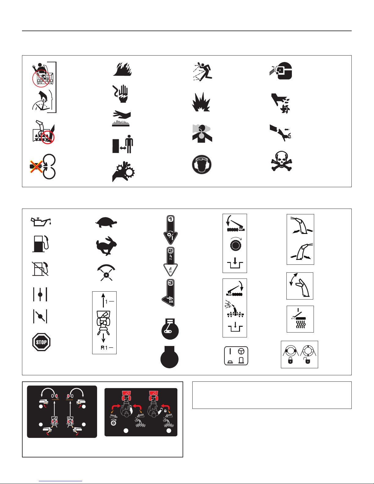
Hazard Symbols and Meanings
Rotating
Impeller
Rotating
Auger
Rotating
Parts
Control Symbols on Equipment
Oil
Fuel
Fuel
Shuto
Choke
O
Choke
On
Stop
Slow
Fast
Auger
Clutch
Forward
Neutral
Reverse
Fire
Shock
Hot
Surface
Safe
Distance
Rotating
Gears
STOP
Engine
On-O
ChokeRun
Engine
Primer
Engine
Run
Engine
Stop
Thrown
Objects
Explosion
Toxic
Fumes
Ear
Protection
Traction
Control
Auger
Control
Electric
Start
Eye
Protection
Moving
Parts
Kickback
Hazardous
Chemical
Discharge
Chute
Chute
Deector
Heated
Hand
Grips
Wheel
Lock
2
1
Easy-Turn™
Traction Control
2
1
1
Free-Hand™ Control
4
NOTE: Not all control symbols shown on this page will appear
on your snowthrower. See Features and Controls section for
the applicable symbols.
2
Page 5
Operator Safety
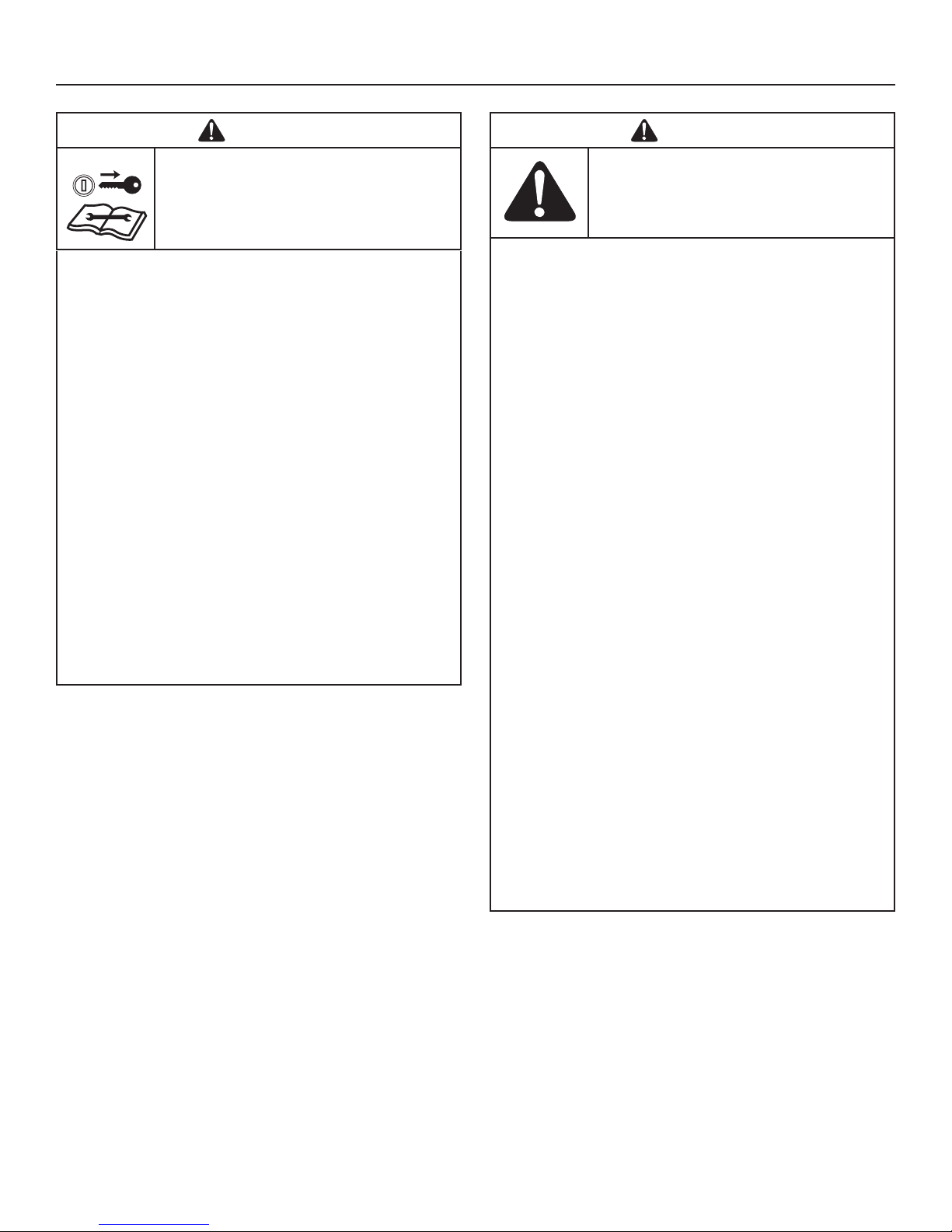
Safety Alert Symbol and Signal Words
The safety alert symbol and signal word (DANGER,
WARNING, CAUTION, or NOTICE) is used to indicate the
likelihood and potential severity of personal injury and/or damage
to the product. In addition, a hazard symbol may be used to
represent the type of hazard.
DANGER indicates a hazard which, if not avoided, will
result in death or serious injury.
WARNING indicates a hazard which, if not avoided, could
result in death or serious injury.
CAUTION indicates a hazard which, if not avoided, could
result in minor or moderate injury.
NOTICE indicates a situation that could result in
damage to the product.
WARNING
Certain components in this product and its related accessories
contain chemicals known to the State of California to cause
cancer, birth defects, or other reproductive harm. Wash hands
after handling.
WARNING
The engine exhaust from this product contains chemicals
known to the State of California to cause cancer, birth defects,
or other reproductive harm.
WARNING
• Hand contact with the rotating impeller inside the discharge
chute is the most common cause of injury associated with
snowthrowers.
• This snowthrower is capable of amputating hands and feet,
and throwing objects. Read and observe all the safety instructions in this manual. Failure to do so could result in death or
serious injury.
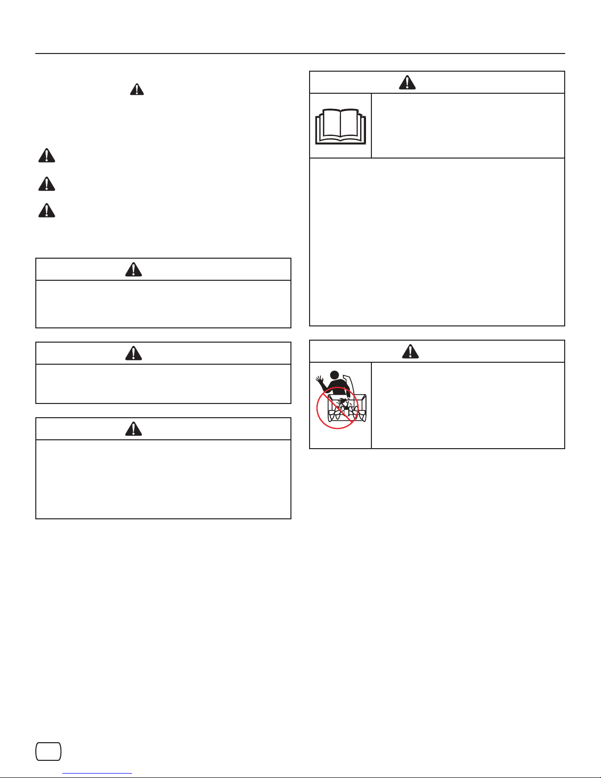
WARNING
Read, understand, and follow all the
instructions on the snowthrower and in the
operator’s manual before operating this unit.
Failure to observe the safet y instructions in this
manual could result in death or serious injury.
• Be thoroughly familiar with the controls and the proper use of
the snowthrower.
• Make sure you are properly trained before operating the
snowthrower.
• Know how to stop the unit and disengage the controls quickly.
• Never allow anyone to operate the snowthrower without
proper instruction.
• Always follow the instructions in the operator’s manual, if the
snowthrower will be stored for an extended period.
• Maintain or replace safety and instruction labels as neces-
sary.
• Never attempt to make major repairs on the snowthrower un-
less you have been properly trained. Improper servicing of the
snowthrower can result in hazardous operation, equipment
damage, and voiding of the product warranty.
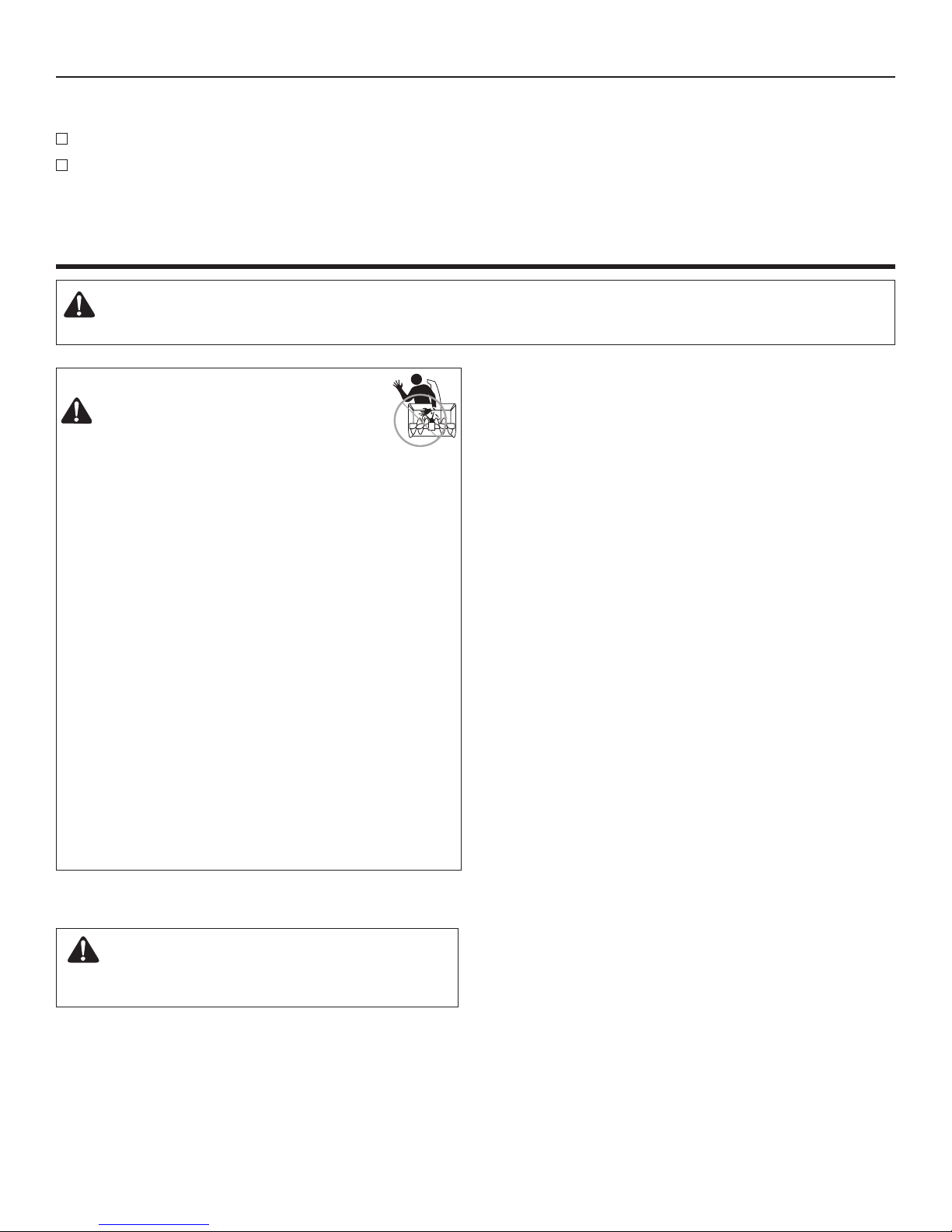
DANGER
Discharge chute contains rotating impeller
to throw snow. Never clear or unclog the
discharge chute with your hands. Fingers can
quickly become caught in the impeller. Always
use a clean-out tool.
Failure to observe these safety instructions
will result in traumatic amputation or severe
laceration.
en
5
Page 6
Operator Safety
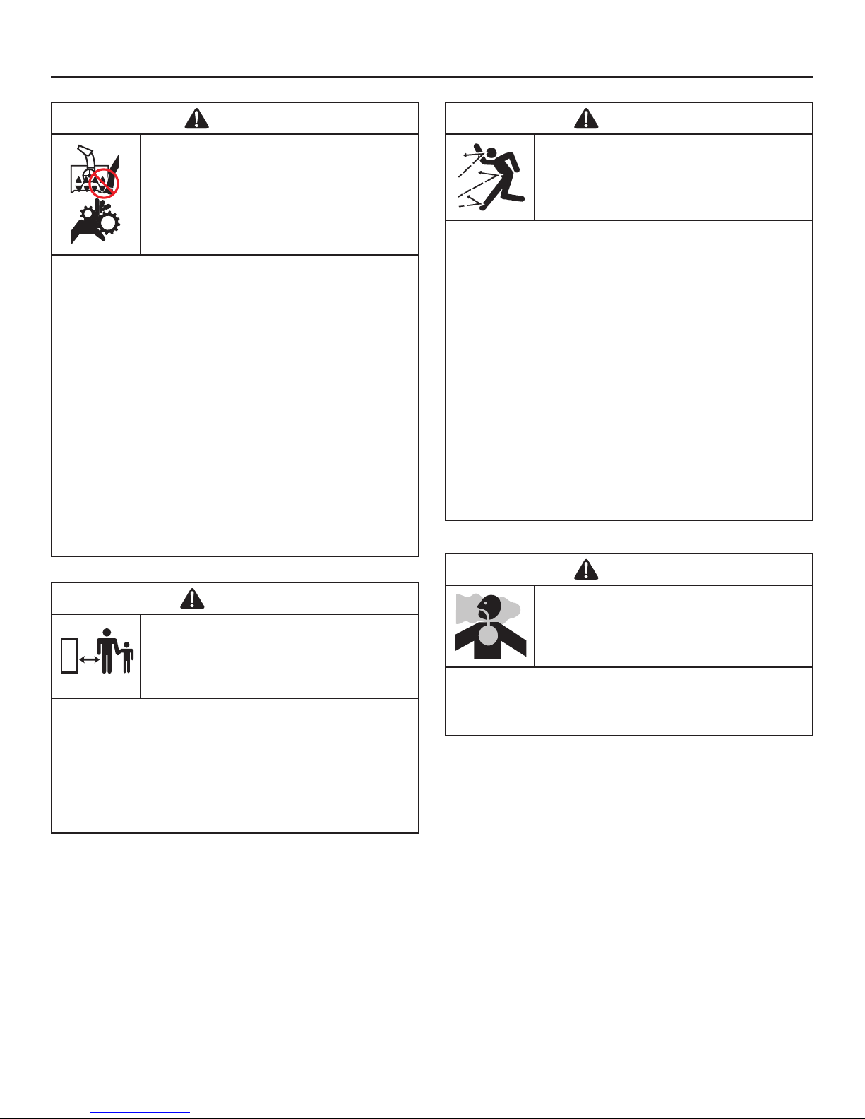
DANGER
Keep hands, feet, and clothing away from
rotating parts. Rotating parts can contact
or entangle hands, feet, hair, clothing, or
accessories.
Failure to observe these safety instructions
will result in traumatic amputation or severe
laceration.
• Whenever cleaning, repairing, or inspecting the snowthrower,
make sure the engine is OFF, spark plug wire is disconnected,
and all moving parts have stopped.
• Do not put hands or feet near or under rotating parts. Keep
clear of the discharge opening at all times.
• Never operate the snowthrower without proper guards, and
other safety devices in place and working.
• Never leave the snowthrower unattended while engine is run-
ning. Always disengage the auger and traction controls, stop
engine, and remove keys.
• Keep all loose clothing away from the front of the snowthrower
and auger. Scarves, mittens, dangling drawstrings, loose
clothes, and pants can quickly become caught in the rotating
device and amputation will occur. Tie up long hair and remove
jewelry.
• Run the machine a few minutes after discharging snow to pre-
vent freeze-up of the collector/impeller.
• Disengage power to the collector/impeller when snowthrower
is transported or not in use.
WARNING
Objects can be picked up by auger and thrown
from chute. Never discharge snow toward
bystanders or allow anyone in front of the
snowthrower. Failure to observe these safety
instructions will result in death or serious injury.
• Always wear safety glasses or eye shields during operation,
and while performing an adjustment or repair.
• Always be aware of the direction the snow is being thrown.
Nearby pedestrians, pets, or property may be harmed by objects being thrown.
• Be aware of your environment while operating the
snowthrower. Don’t run over items such as gravel, doormats,
newspapers, toys, and rocks hidden under snow, as they can
all be thrown from the chute or jam in the auger.
• Use extreme caution when operating on or crossing gravel
drives, walks, or roads.
• Adjust the collector housing height to clear gravel or crushed
rock surface.
• Never operate the snowthrower near glass enclosures, automobiles, window wells, drop-os, and the like without proper
adjustment of the discharge chute angle.
• Familiarize yourself with the area in which you plan to operate
the snowthrower. Mark o boundaries of walkways and drive-
ways.
WARNING
Tragic accidents can occur if the operator is
not alert to the presence of children. Children
are often attracted to the unit and the operating
activity. Never assume the children will remain
where you last saw them.
• Keep children out of the area during operation. Children are
often attracted to the equipment. Be mindful of all persons
present.
• Be alert and turn unit o if children enter the area.
• Never allow children to operate the unit.
• Use extra care when approaching blind corners, shrubs,
trees, or other objects that may obscure vision. Children may
be present.
WARNING
Engines give o carbon monoxide, an
odorless, colorless, poison gas. Breathing
carbon monoxide can cause nausea, fainting,
or death.
• Start and run engine outdoors.
• Do not run the engine in an enclosed area, even if doors or
windows are open.
6
Page 7
Operator Safety
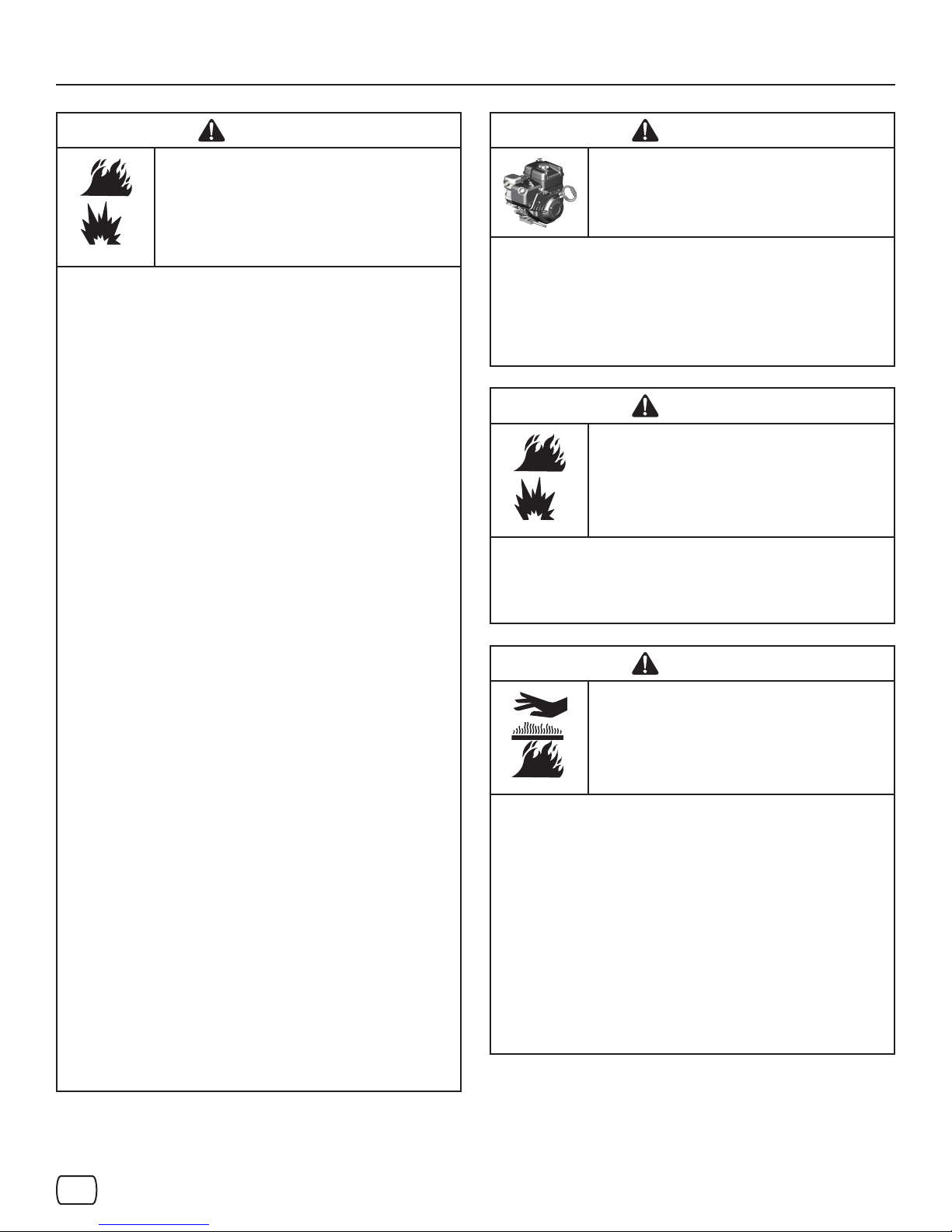
WARNING
Fuel and its vapors are extremely ammable
and explosive. Always handle fuel with
extreme care.
Failure to observe these safety instructions can
cause a re or explosion which will result in
severe burns or death.
WHEN ADDING FUEL
• Turn o engine and let cool at least 2 minutes before removing
the fuel cap and adding fuel.
• Fill fuel tank outdoors or in a well ventilated area.
• Do not overll the fuel tank. To allow for the expansion of gasoline, do not ll above the bottom of the fuel tank neck.
• Keep fuel away from sparks, open ames, pilot lights, heat,
and other ignition sources.
• Check fuel lines, cap, and ttings frequently for cracks or
leaks. Replace if necessary.
• Use an approved fuel container.
• If fuel spills, wait until it evaporates before starting engine.
WHEN STARTING ENGINE
• Ensure that spark plug, muer, fuel cap, and air cleaner (if
equipped) are in place and secured.
• Do not crank the engine with the spark plug removed.
• If fuel is spilled, do not attempt to start the engine, but move
the snowthrower away from the area of the spill, and avoid
creating any source of ignition, until the fuel vapors have dissipated.
• Do not over-prime the engine. Follow the engine starting instructions in this manual.
• If the engine oods, set choke (if equipped) to OPEN/RUN position, move throttle (if equipped) to FAST position and crank
until engine starts.
WHEN OPERATING EQUIPMENT
• Do not tip the snowthrower at an angle which causes the fuel
to spill.
• Do not choke the carburetor to stop the engine.
• Never run the engine with the air cleaner assembly (if
equipped) or the air lter (if equipped) removed.
WHEN CHANGING OIL
• If you drain the oil from the top oil ll tube, the fuel tank must
be empty or fuel can leak out and result in a re or explosion.
WHEN TRANSPORTING EQUIPMENT
• Transport with fuel tank EMPTY, or with fuel shut-o valve
OFF.
WHEN STORING GASOLINE OR EQUIPMENT WITH FUEL
IN TANK
• Store away from furnaces, stoves, water heaters, or other appliances that have pilot light or other ignition source because
they can ignite fuel vapors.
WARNING
Safe operation of the snowthrower requires the
proper care and maintenance of the engine.
• Disengage all clutches and shift into neutral before starting the
engine may cause personal injury.
• Let the engine adjust to outdoor temperatures before starting
to clear snow.
• Use a grounded three-wire plug for all snowthrowers equipped
with electric drive motors or electric starting motors.
WARNING
Starting engine creates sparking.
Sparking can ignite nearby ammable gases.
Explosion and re could result.
• If there is natural or LP gas leakage in area, do not start
engine.
• Do not use pressurized starting uids because vapors are
ammable.
WARNING
Running the engine produces heat. Engine
parts, especially muer, become extremely
hot.
Failure to observe these safety instructions
could result in severe thermal burns on
contact.
• Never touch a hot engine or muer. Allow muer, engine cylinder, and ns to cool before touching.
• Remove debris from muer area and cylinder area.
• Install and maintain in working order a spark arrester before
using equipment on forest-covered, grass-covered, or brushcovered unimproved land.
• It is a violation of California Public Resource Code, Section 4442, to use or operate the engine on any forest-covered,
brush-covered, or grass-covered land unless the exhaust sys-
tem is equipped with a spark arrester, as dened in Section
4442, maintained in eective working order. Other states or
federal jurisdictions may have similar laws. Contact the original equipment manufacturer, retailer, or dealer to obtain a
spark arrester designed for the exhaust system installed on
this engine.
en
7
Page 8
Operator Safety
WARNING
This snowthrower must be properly maintained
to ensure safe operation and performance.
Failure to observe the safety instructions in this
manual could result in death or serious injury.
• When performing any maintenance or repairs on the
snowthrower, shut OFF the engine, disconnect spark plug
wire, and keep the wire away from the plug to prevent someone from accidently starting the engine.
• Check shear bolts and other hardware at frequent intervals for
proper tightness.
• Keep nuts and bolts tight and keep snowthrower in good con-
dition.
• Never tamper with safety devices. Check their proper opera-
tion regularly and make necessary repairs if they are not functioning properly.
• Components are subject to wear, damage, and deteriora-
tion. Frequently check components and replace with recommended parts, when necessary.
• Check control operation frequently. Adjust and service as re-
quired.
• Use only factory authorized replacement parts, or like, parts
when making repairs.
• Always comply with factory specications on all settings and
adjustments.
• Use only factory authorized, or like, attachments and acces-
sories such as wheel weights, counterweights, or cabs.
• Never attempt to make any adjustments while the engine is
running (except when specically recommended by the fac-
tory).
WARNING
This snowthrower is only as safe as the
operator. If it is misused, or not properly
maintained, it can be dangerous. Remember
you are responsible for your safety and those
around you.
• Keep the area of operation clear of all persons, particularly
small children and pets.
• Thoroughly inspect the area where the snowthrower will be
used and remove all doormats, sleds, boards, wires, and
other foreign objects.
• Do not operate the snowthrower without wearing adequate
winter clothing.
• Wear footwear that will improve footing on slippery surfaces.
• Use caution to avoid slipping or falling especially when operat-
ing the snowthrower in reverse.
• Never operate the snowthrower without good visibility or light.
Always be sure of your footing, and keep a rm hold on the
handles.
• Do not clear snow across the face of slopes. Use extreme
caution when changing direction on slopes. Do not attempt to
clear steep slopes.
• Do not overload the machine capacity by attempting to clear
snow too quickly.
• Never operate the snowthrower at high transport speeds on
slippery surfaces. Look behind the snowthrower and use care
when operating in reverse.
• Do not use the snowthrower on surfaces above ground level
such as roofs of residences, garages, porches, or other such
structures or buildings.
• Operators should evaluate their ability to operate the
snowthrower safely enough to protect themselves and others
from injury.
• The snowthrower is intended to remove snow only. Do not use
the snowthrower for any other purpose.
• Do not carry passengers.
• After striking a foreign object, shut OFF the engine, discon-
nect the cord on electric motors, thoroughly inspect the
snowthrower for any damage, and repair the damage before
restarting and operating the snowthrower.
• If the snowthrower vibrates abnormally, shut OFF the engine.
Vibration is generally a warning of trouble. See an authorized
dealer if necessary for repairs.
• For models equipped with electric starting motors, disconnect
the power cord after the engine starts.
8
Page 9
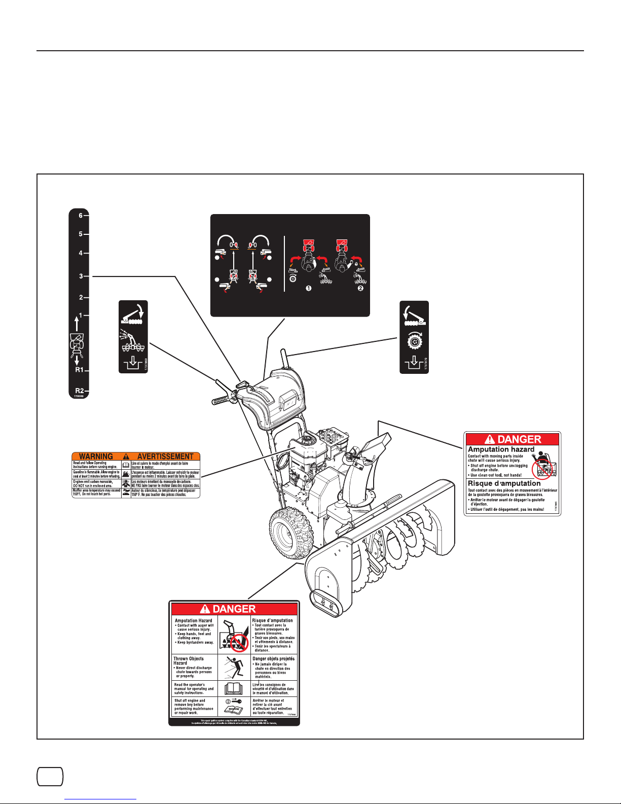
Safety Decals
Operator Safety
Before operating your snowthrower, read the safety decals
installed on your snowthrower. The cautions and warnings
are for your safety. To avoid a personal injury or damage to
your snowthrower, understand and follow all the safety decals.
Part No. 1754679
Main Dash Decal
Part No. 1751582
Shift Decal
Part No. 1737869
Auger Control Decal
2
1
2
1
If any safety decals become worn or damaged and cannot
be read, order replacement decals from your local dealer.
1754679
Part No. 1737870
Traction Control Decal
Part No. 278297
Engine Decal
Product ID Number &
Serial Number Decal
(Rear of Motor Box)
Figure 1
en
Part No. 1737865
Chute Danger Decal
Part No. 1737866
Auger Danger Decal
9
Page 10
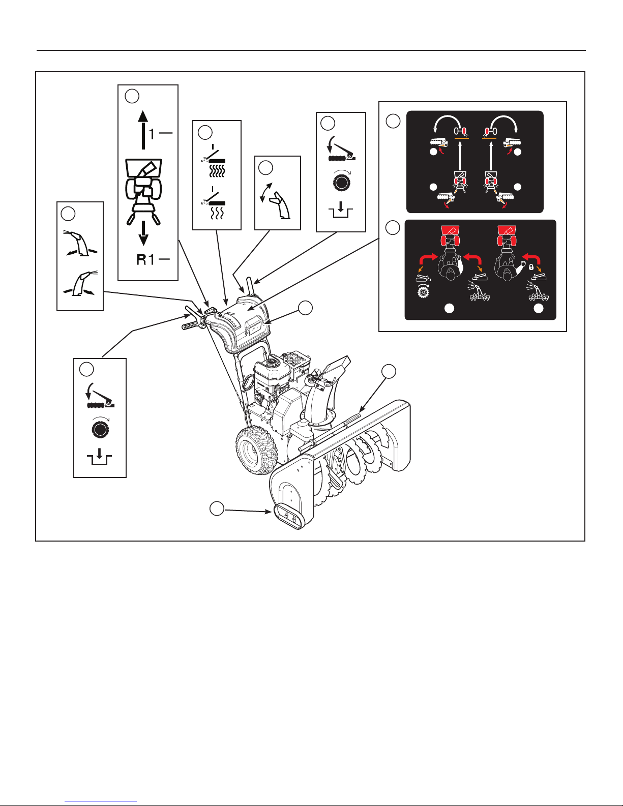
Features and Controls
A
G
E
K
2
2
D
1
1
C
F
J
B
H
1
2
Figure 2
SNOWTHROWER CONTROLS
A. Speed Select Lever — Allows the operator to select forward
and reverse speeds (see Figure 2). To shift, move speed se lect lever to desired position.
NOTICE: Do not move speed select lever while Traction
Control is engaged. This may result in severe damage
to the drive system.
B. Auger Control Lever — Used to engage and disengage the
auger and impeller. To engage push down, to disengage re-
lease.
C. Chute Rotation Switch — Used to rotate the discharge
chute to the left or right.
D. Deector Control Switch — Used to control the angle of the
chute deector (up or down).
10
I
E. Easy-TurnTM Traction Control — When engaged, allows the
operator to release one drive wheel, but allows the other
wheel to continue driving for easy turning.
F. Free-HandTM Control — After engaging the traction control
(left hand) and auger control (right hand), allows the operator
to release the auger control lever to use the other controls.
G. Traction Control Lever — Used to propel snowthrower for-
ward or reverse. Push down to engage, release to disengage.
See also, “Free-Hand Control”.
H. Clean-Out Tool — Used to remove snow and debris from the
discharge chute and the auger housing.
I. Skid Shoes — Used to adjust the ground clearance of the
auger housing.
Page 11
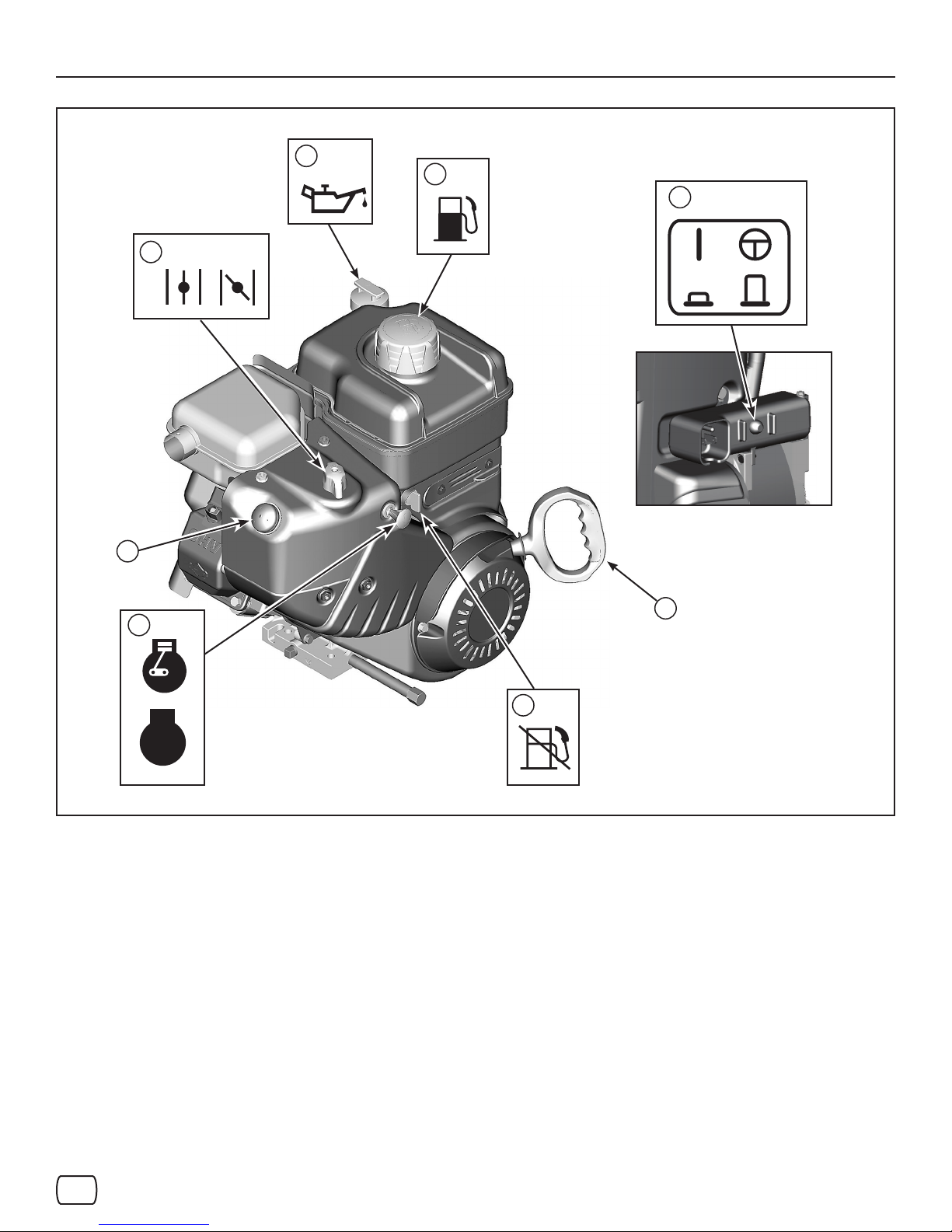
Features and Controls
G
F
B
A
C
E
D
H
STOP
Figure 3
SNOWTHROWER CONTROLS (Continued)
J. Headlight — Used to operate the snowthrower in poor light-
ing conditions.
K. Grip Warmer Switch — Used to warm the hand grips
(On/O).
ENGINE CONTROLS
A. Choke Control Knob — Used to start a cold engine (see
Figure 3).
B. Electric Start Button — Used to start the engine using the
electric starter.
C. Primer Button — Used to inject fuel directly into the carbure tor manifold to ensure fast starts in cool weather.
D. Safety Key — Must be inserted to start engine. Pull out to
stop. Do not turn safety key.
E. Starter Cord Handle — Used to start the engine manually.
F. Fuel Tank and Cap — Fill the fuel tank to approximately
1-1/2 in. (38 mm) below the top of the neck to allow for fuel
expansion.
G. Oil Fill Cap (Extended Dipstick)
H. Fuel Shut-O Valve (if equipped) — Used to turn the fuel
supply o for out-of-season storage.
en
11
Page 12
Operation
BEFORE OPERATING SNOWTHROWER
Check the fasteners. Make sure all fasteners are tight.
Read this Operator’s Manual and Operator Safety before
operating your snowthrower. Compare the illustrations with
your snowthrower to familiarize yourself with the location of
various controls and adjustments. Save this manual for future reference.
WARNING: The operation of any snowthrower can result in foreign objects being thrown into the eyes, which
can result in severe eye damage. Always wear safety glasses or eye shields before beginning snowthrower
operation. We recommend standard safety glasses or Wide Vision Safety Mask over spectacles.
SAFETY SYSTEM TESTS
WARNING
Amputation Hazard
This snowthrower is equipped with several mechanical
safety systems designed to keep the operator safe while
using the unit. Check the operation of these systems
regularly using the safety system tests listed. If the unit
fails to operate as described, DO NOT operate it. See your
authorized dealer for service immediately.
Test 1 – Auger/Impeller Control
With the engine running:
• Press down on the auger control lever. (The auger/impeller
should rotate.)
• Release the auger control lever. (The auger/impeller should
stop within 5 seconds.)
Test 2 – Traction Drive Control
With the engine running and speed control in 1st gear:
• Press down on the traction control lever. (The unit should
move forward.)
• Release the traction control lever. (The unit should stop.)
Test 3 - Free Hand Control
With the engine running:
• Engage the auger and traction control levers, then release
the auger control lever. (Both controls should remain
engaged.)
• Next, release the traction control lever. (Both controls should
release.)
OPERATE THE SNOWTHROWER
CAUTION: Operation with a Snow Cab. Wind may
blow exhaust gasses back towards the operator. If
you notice the smell of exhaust, change direction of
operation.
NOTICE: Do not throw snow toward a building as hidden objects
could be thrown with sucient force to cause damage.
1. Start the engine. See Start the Engine in this section.
2. Press the chute rotation switch (C, Figure 2) to rotate the dis-
charge chute left or right.
NOTE: This snowthrower was shipped WITH OIL in the engine.
See “Before Starting Engine” instructions in the Operation
section of this manual before starting engine.
NOTICE: Before operating, make sure the area in front of the
snowthrower is clear of bystanders or obstacles.
3. Press the deector control switch (D) to control the angle of
the chute deector.
4. Fully press and hold the auger control lever (B) to engage
the auger rotation. Releasing the auger control lever will
disengage the auger - unless the Free-Hand™ control is activated.
5. Fully press and hold the traction/Free-Hand™ control lever
(G) to engage the traction drive and begin moving the snowthrower. To disengage the traction drive, completely release
the lever.
6. When BOTH levers are pressed, the Free-Hand™ control is
activated. This allows you to release the auger control lever to
use the other controls. The auger will continue to run until the
traction/Free-Hand™ control lever is released.
NOTE: Always release the traction control lever before moving
the speed select lever.
7. Use the speed select lever (A) to select the forward drive
speed. Set the speed select lever to one of the following positions as determined by snow conditions:
1-2 Wet, Heavy, Slushy, Extra Deep
3 Moderate
4-5 Very Light
6 Transport
NOTE: When clearing wet, heavy, snow, it is recommended that
the ground speed of the unit be reduced, maintained full throttle
and do not attempt to clear the full width of the unit.
8. Press the grip warmer switch (K) to heat the hand grips.
9. To stop moving forward, release the traction control lever (G).
10. To move the snowthrower backwards, move the speed select
lever into either rst or second reverse position and engage
the traction control lever.
12
Page 13
STOP THE SNOWTHROWER
1. Release the traction control lever (C, Figure 2).
2. Pull out the safety key (D, Figure 3).
3. Keep the safety key out of the reach of children.
Operation
2
2
WARNING: Never run engine indoors or in
an enclosed, poor ventilated area. Engine
exhaust contains CARBON MONOXIDE, an
ODORLESS and DEADLY GAS.
• Keep hands, feet, hair, and loose clothing
away from any moving parts on engine and
snowthrower.
• Temperature of muer and nearby areas can
exceed 150°F (66°C). Avoid these areas.
• DO NOT allow children or young teenagers to
operate or be near snowthrower while it is
operating.
WARNING: Read Operator’s Manual before
operating machine. This machine can be
dangerous if used carelessly.
• Never operate the snowthrower without all
guards, covers, shields in place.
• Never direct discharge towards windows or
allow bystanders near machine while engine is
running.
• Stop the engine whenever leaving the operating
position.
• Disconnect spark plug before unclogging the
impeller housing or the discharge chute and
before making repairs or adjustments.
• When leaving the machine, remove the safety key.
To reduce the risk of re, keep the machine clean
and free from spilled gas, oil, and debris.
1
Figure 4
1
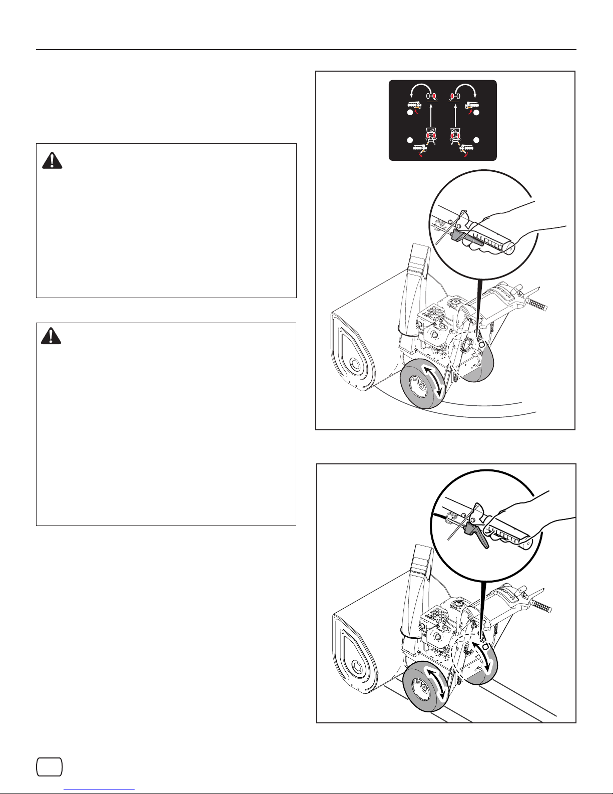
EASY-TURNTM TRACTION CONTROL
For easy turning when using the snowthrower, squeeze the EasyTurn™ lever.
Engaging the Easy-Turn™ lever releases the left or right traction
wheel, but allows the opposite wheel to continue driving. Figure 4
shows the left Easy-Turn lever engaged.
Releasing the Easy-Turn™ lever automatically engages both
drive wheels for full traction (see Figure 5).
NOTE: The Easy-TurnTM will be more dicult to activate under a
heavy load. Activate the lever before beginning a turn.
en
Figure 5
13
Page 14
Operation
CHECK THE OIL (BEFORE STARTING ENGINE)
NOTE: The engine was shipped from the factory lled with oil.
Check the level of the oil. Add oil as needed.
1. Make sure the unit is level. Use a high quality detergent oil
classied “For Service SF, SH, SJ, SL, or higher”.
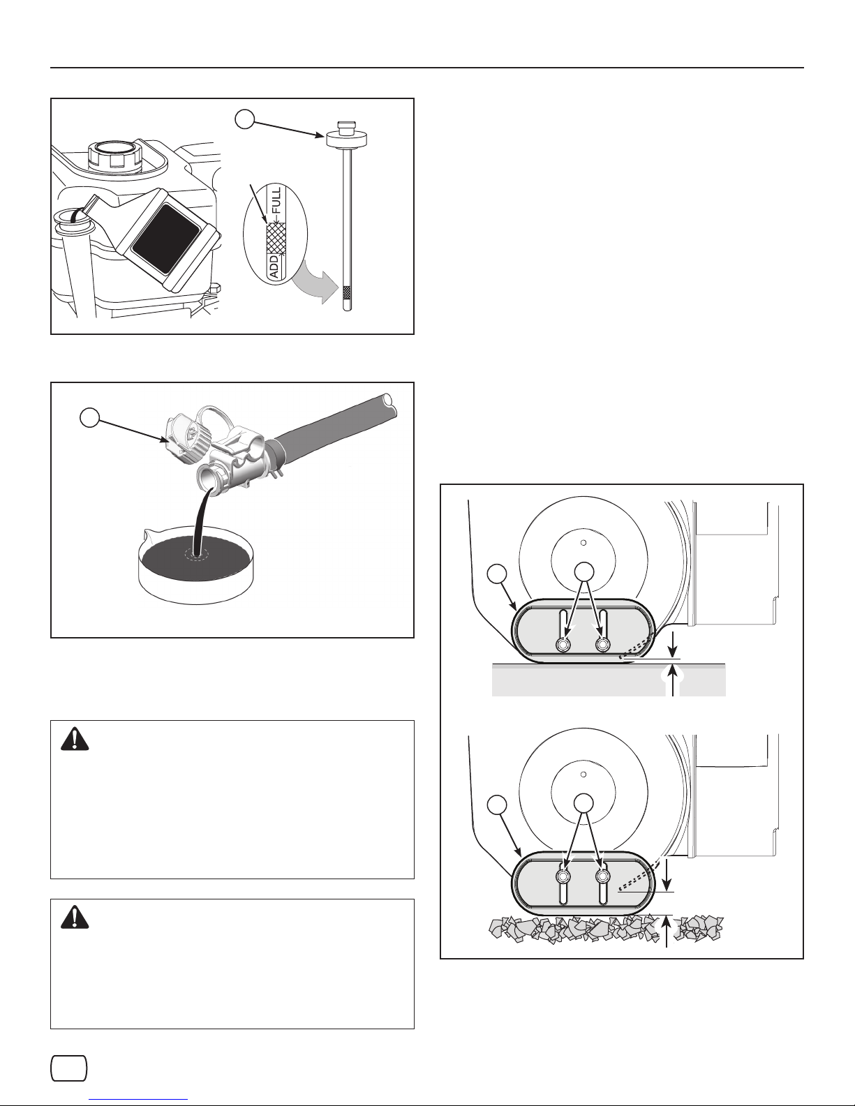
2. Remove the oil ll cap/dipstick (A, Figure 6) and wipe with a
clean cloth.
3. Insert the oil ll cap/dipstick and turn clockwise to tighten.
4. Remove the oil ll cap/dipstick and check the oil.
NOTE: Do not check the level of the oil while the engine runs.
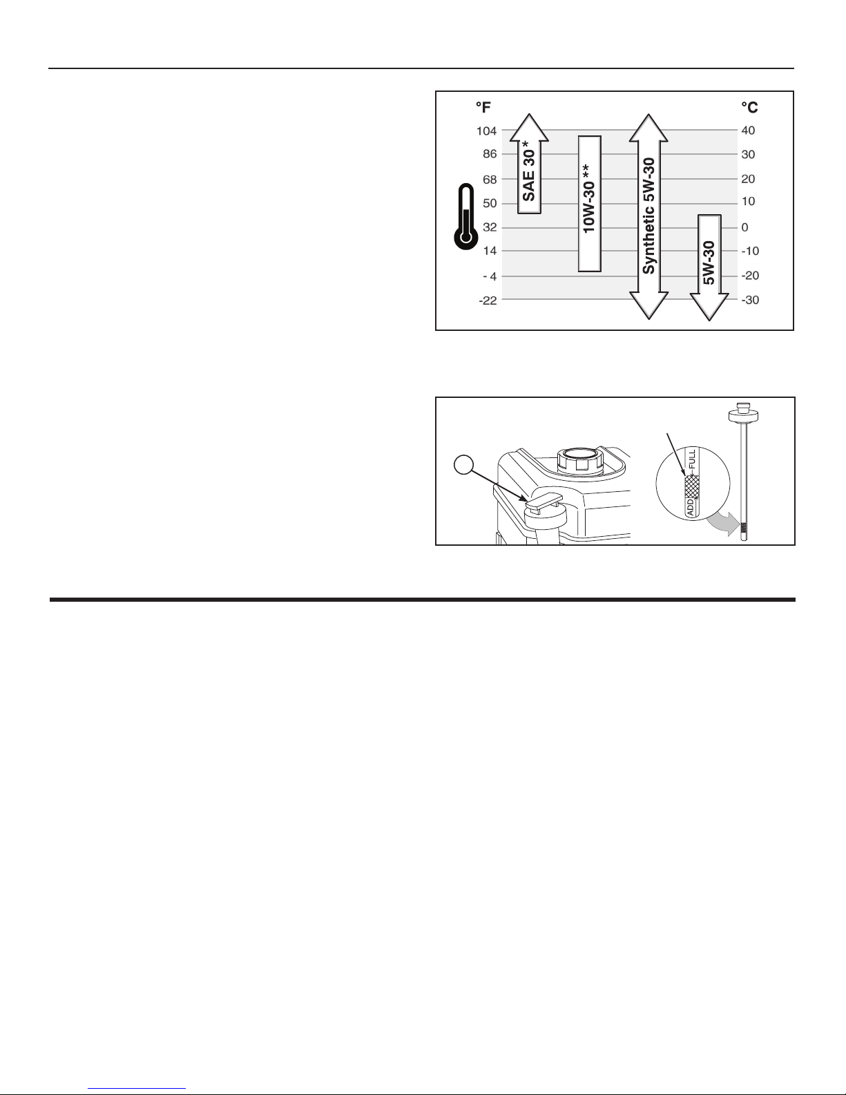
5. If necessary, add oil until the oil reaches the FULL mark
on the oil ll cap/dipstick. Do not add too much oil.
6. Tighten the oil ll cap/dipstick securely each time you check
the oil level.
NOTE: For extreme cold operating conditions of 0°F (-18°C)
and below, use a synthetic 5W30 motor oil for easier starting.
NOTE: S.A.E. 5W30 motor oil may be used to make starting
easier in areas where the temperature is 20°F (-7°C) to 0°F
(-18°C). Synthetic 5W30 is acceptable for all temperatures.
DO NOT mix oil with gasoline. See Chart for oil recommendations.
* Below 40°F (4°C) the use of SAE 30 will result in hard starting.
** Above 80°F (27°C) the use of 10W-30 may cause increased oil con-
sumption. Check oil level more frequently.
FULL
A
FUEL RECOMMENDATIONS
Fuel must meet these requirements:
• Clean, fresh, unleaded gasoline.
• A minimum of 87 octane/87 AKI (91 RON). High altitude
use, see below.
• Gasoline with up to 10% ethanol (gasohol) is acceptable.
CAUTION: Do not use unapproved gasolines, such as E15 and
E85. Do not mix oil in gasoline or modify the engine to run on
alternate fuels. Use of unapproved fuels will damage the engine
components and void the engine warranty.
To protect the fuel system from gum formation, mix a fuel stabilizer into the fuel. See Storage. All fuel is not the same. If starting or performance problems occur, change fuel providers or
change brands. This engine is certied to operate on gasoline.
The emissions control system for this engine is EM (Engine
Modications).
Figure 6
HIGH ALTITUDE
At altitudes over 5,000 feet (1524 meters), a minimum 85 octane/85 AKI (89 RON) gasoline is acceptable. To remain emissions compliant, high altitude adjustment is required. Operation
without this adjustment will cause decreased performance, increased fuel consumption, and increased emissions. See an
authorized Briggs & Stratton Dealer for high altitude adjustment
information.
Operation of the engine at altitudes below 2,500 feet (762 meters) with high altitude adjustment is not recommended.
14
Page 15
Operation
ADDING FUEL
WARNING
Fuel and its vapors are extremely ammable
and explosive.
Fire or explosion can cause severe burns or
death.
When Adding Fuel
• Turn engine o and let engine cool at least 2 minutes
before removing the fuel cap.
• Fill fuel tank outdoors or in well-ventilated area.
• Do not overll fuel tank. To allow for expansion of the fuel,
do not ll above the bottom of the fuel tank neck.
• Keep fuel away from sparks, open ames, pilot lights,
heat, and other ignition sources.
• Check fuel lines, tank, cap, and ttings frequently for
cracks or leaks. Replace if necessary.
• If fuel spills, wait until it evaporates before starting engine.
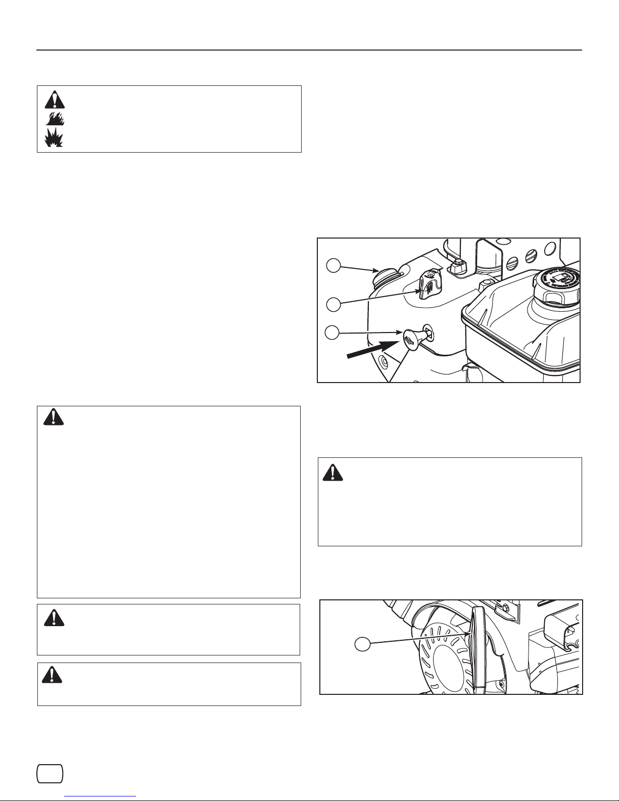
START THE ENGINE
Be sure that engine oil is at FULL mark on the oil ll cap/dipstick. The
snowthrower engine is equipped with an A.C. electric starter and recoil
starter. Before starting the engine, be certain that you have read the following information.
If engine oods, set the choke to the OPEN/RUN position and crank
until the engine starts.
Start the engine as follows:
1. Check the oil level. See Check the Oil section.
2. Make sure equipment drive controls are disengaged.
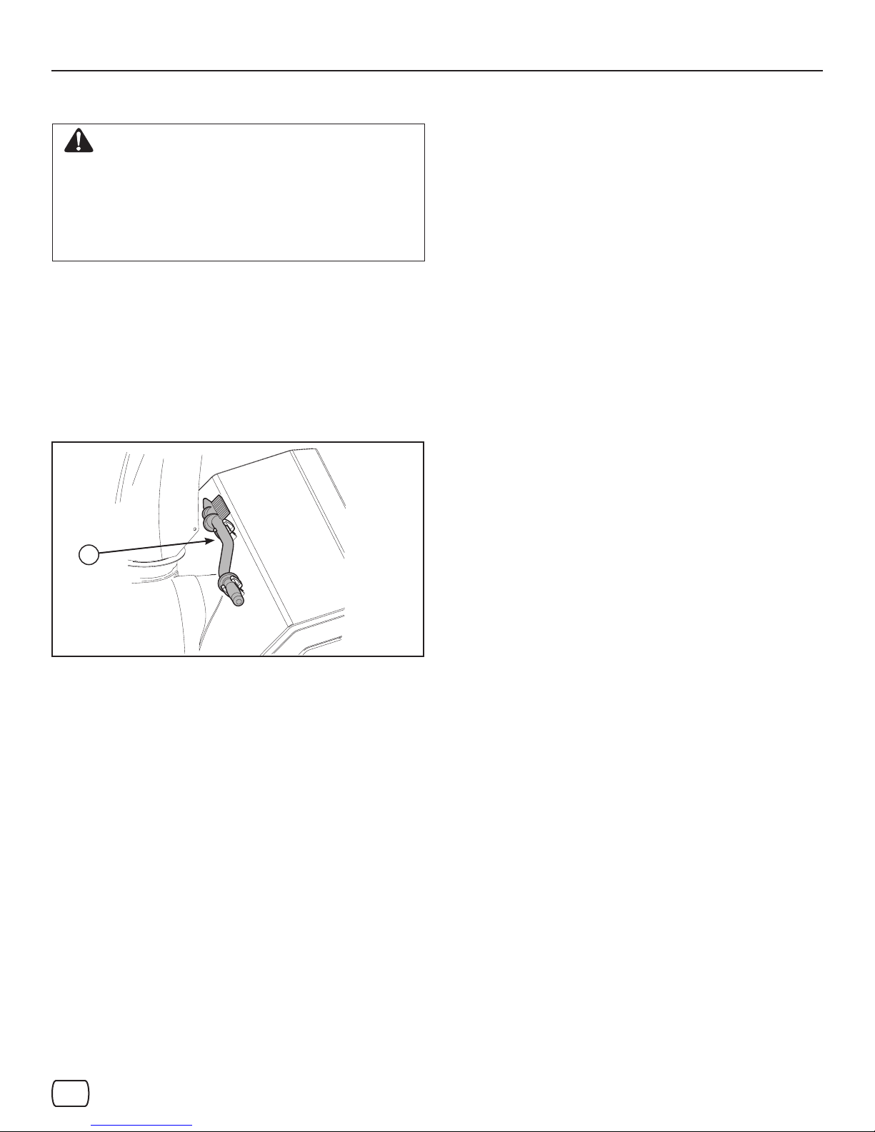
3. Insert the safety key (A, Figure 7) into the safety key slot
and push fully in to the RUN position.
4. Turn the choke control knob (B) to the CHOKE position.
NOTE: Do not use the choke to start a warm engine.
5. Push the primer button (C) two times.
NOTE: Do not use the primer to start a warm engine.
NOTE: Ensure that electric extension cord is removed from the
power receptacle.
C
B
A
Figure 7
WARNING: The electric starter is equipped with a
three−wire power cord and plug designed to operate
on AC house hold current. The power cord must be
properly grounded at all times to avoid the possibility
of electric shock which can cause injury to the
operator. Follow all instructions carefully as set forth:
Make sure your house has a three−wire grounded
system.
If you are not sure, ask a licensed electrician. If your
house does not have a three−wire grounded system,
do not use this electric starter under any condition.
If your house has a three−wire grounded system but
a three-hole receptacle is not available to connect the
electric starter, have a three−hole receptacle installed
by a licensed electrician.
WARNING: To connect power cord, always
connect the power cord rst to the switch box
located on the engine and then plug the other end
into a three−hole grounded receptacle.
WARNING: To disconnect the power cord,
always unplug the end connected to the three−
hole grounded receptacle rst.
6. Rewind Start: Firmly hold the starter cord handle (A, Figure 8).
Pull the starter cord handle slowly until resistance is felt, then pull
rapidly.
WARNING: Rapid retraction of the starter cord
(kickback) will pull your hand and arm toward
the engine faster than you can let go. Broken
bones, fractures, bruises, or sprains could result.
When starting engine, pull the starter cord slowly
until resistance is felt and then pull rapidly to avoid
kickback.
NOTE: If the engine does not start after three attempts, see
an authorized dealer.
A
Figure 8
en
en
15
Page 16
Operation
7. Electric Start: First connect the extension cord to the
power cord receptacle and then into a wall receptacle. If additional extension cord is required, make sure it is three-wire.
WARNING: If the extension cord is damaged,
it must be replaced by the manufacturer (or its
service agent) or a similarly qualied person
to avoid a hazard.
8. Electric Start: Depress the starter push button (A, Figure 9).
After you start the engine, rst disconnect the extension cord
from the wall receptacle and then from the power cord receptacle (B).
A
B
STOP THE ENGINE
Before stopping the engine for a few minutes to help dry o
any moisture on the engine.
WARNING: Gasoline and vapors are extremely
ammable and explosive. Fire or explosion can
cause severe burns or death. DO NOT choke
the carburetor to stop the engine.
1. Remove the safety key (A, Figure 7).
2. Keep the safety key out of the reach of children.
NOTE: Do not lose the safety key. Keep the safety key in a
safe place. The engine will not start without the safety/ignition key.
Figure 9
IMPORTANT: To extend the life of the starter, use
short starting cycles (ve seconds maximum). Wait
one minute between starting cycles.
NOTE: If the engine does not start after three attempts, see
an authorized dealer.
16
Page 17
Operation
CLEAR A CLOGGED DISCHARGE CHUTE
WARNING: Hand contact with the rotating
impeller inside the discharge
chute is the most common cause of injury
associated with snowthrowers. Never clear or
unclog discharge chute with your hands, or while
engine is running. Fingers can quickly become
caught and traumatic amputation or severe
laceration can result.
• SHUT OFF THE ENGINE!
• Wait 10 seconds to be sure that the impeller blades
have stopped rotating.
• Always use a clean-out tool, not your hands.
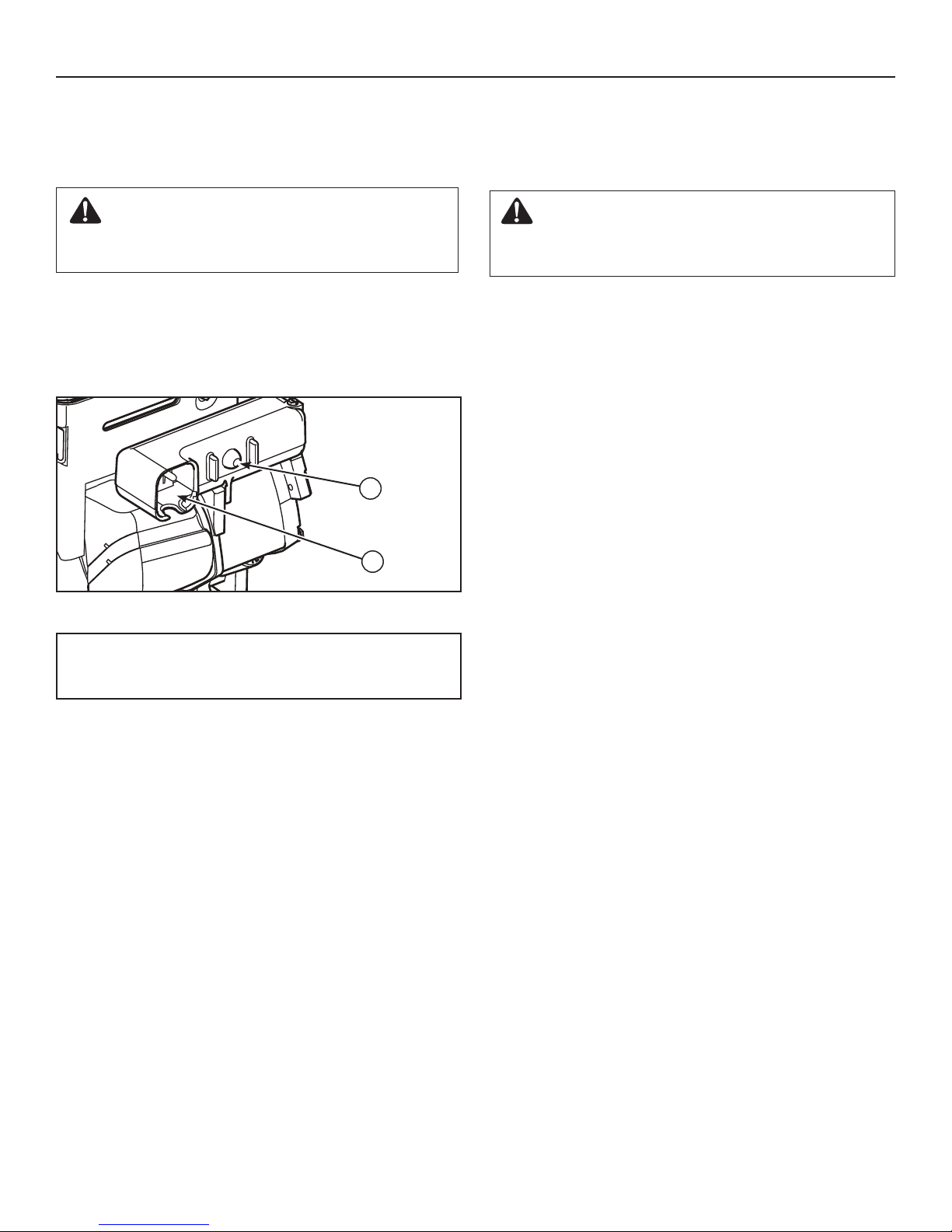
A clean-out tool (A, Figure 10) is attached to either the handle or
the top of the auger housing. Use the clean-out tool to remove
snow from the auger housing.
A
OPERATING TIPS
1. Most ecient snowthrowing is accomplished when snow
is removed immediately after it falls.
2. For complete snow removal, slightly overlap each swath previously taken.
3. Snow should be discharged downwind whenever possible.
4. For normal usage, set the skids 1/8 inch (3 mm) below the
scraper bar. For extremely hard-packed snow surfaces,
the skids may be adjusted upward to ensure cleaning ef-
ciency.
5. On gravel or crushed rock surfaces, the skids should be
set at 1-1/4 inch (32 mm) below the scraper bar (see “Adjust Skid Height” in the Maintenance section of this manual). Rocks and gravel must not be picked up and thrown
by the machine.
6. After the snowthrowing job has been completed, allow the
engine to idle for a few minutes, to melt snow and ice accumulated on the engine.
7. Clean the snowthrower thoroughly after each use.
8. Remove ice and snow accumulation and all debris from
the entire snowthrower, and ush with water (if possible)
to remove all salt or other chemicals. Wipe snowthrower
dry.
9. Before starting snowthrower, always inspect augers and
impeller for ice accumulation and/or debris, which could
result in snowthrower damage.
10. Check oil level before every start. Make sure the oil is at
the FULL mark on the oil ll cap/dipstick.
Figure 10
en
17
Page 18

Maintenance
MAINTENANCE CHART
SNOWTHROWER
After Each Use
Remove the snow and slush o snowthrower to prevent
freezing of controls
Every 8 Hours or Daily
Perform snowthrower safety tests
Every 25 Hours or Annually *
Check tire pressure
Check snowthrower for loose hardware
See Dealer Annually to
Lubricate control levers and linkages
Lubricate deector hinge
Lubricate deector motor (if equipped)
Lubricate chute rotation gear (if equipped)
EMISSIONS CONTROL STATEMENT
Maintenance, replacement, or repair of the emissions control
devices and systems may be performed by any non-road engine repair establishment or individual. However, to obtain “no
charge” emissions control service, the work must be performed
by a factory authorized dealer. See the Emissions Warranty.
ENGINE
First 5 Hours
Change engine oil
Every 8 Hours or Daily
Check engine oil level
Every 50 Hours or Annually *
Change engine oil
Check muer and muer guard.
See Dealer Annually to
Replace spark plug
Check valve clearance
* Not required unless there are problems with engine
performance.
Drain Oil – Position snowthrower so that the oil drain plug (A,
Figure 12) is lowest point on engine. When the engine is warm,
remove oil drain plug and oil ll cap and drain oil into a suitable
container.
Replace oil drain plug and tighten securely. Rell crankcase
with the recommended motor oil.
ENGINE MAINTENANCE
Check Crankcase Oil Level - Before starting engine and after
each 8 hours of continuous use. Add the recommended motor
oil as required.
NOTE: Over lling the engine can aect performance. Tighten
the oil ll cap securely to prevent leakage.
Change Oil - Every 50 hours of operation or at least once a
year, even if the snowthrower is not used for fty hours. Use
a clean, high quality detergent oil. Fill the crankcase to FULL
line on dipstick (A, Figure 11). Be sure original container is
marked: A.P.I. service “SF” or higher. Do not use SAE10W40
oil (as it may not provide proper lubrication). See Chart for oil
recommendations.
* Below 40°F (4°C) the use of SAE 30 will result in hard starting.
** Above 80°F (27°C) the use of 10W-30 may cause increased oil con-
sumption. Check oil level more frequently.
18
Page 19
A
Full
Figure 11
A
Maintenance
This snowthrower is equipped with two height adjust skids,
secured to the outside of the auger housing. These elevate the
front of the snowthrower.
When removing snow from a hard surface area such as a paved
driveway or walk, adjust the skids up to bring the front of the
snowthrower down.
When removing snow from rock or uneven construction, raise
the front of the snowthrower by moving the skids down. This will
help to prevent rocks and other debris from being picked up and
thrown by the augers.
1. Determine how much clearance you want between the scraper
bar at the bottom of the auger housing and the ground. If
clearing a gravel surface, enough ground clearance is needed
to prevent the unit from picking up rocks.
2. Place a block equal to the desired ground clearance under the
scraper bar.
3. Loosen the skid shoe mounting nuts (A, Figure 13) and push
the skid shoe (B) down until it touches the ground. Re-tighten
mounting nuts.
4. Set the skid shoe on the other side at the same height.
Figure 12
SKID SHOE HEIGHT ADJUSTMENT
DANGER: Amputation Hazard
The discharge chute contains a rotating impeller to
throw snow. Fingers can quickly become caught and
traumatic amputation or severe laceration will result.
Hand contact with the rotating impeller inside the
discharge chute is the most common cause of injury
associated with snowthrowers.
Turn the engine OFF, wait for all moving parts to
stop, and remove the engine key before performing
any maintenance or repairs.
WARNING: Thrown Objects Hazard
Objects such as gravel, rocks, or other debris, if
struck by the impeller, may be thrown with sucient
force to cause personal injury, property damage, or
damage to the snowthrower.
Be sure to set the skid shoes at the proper height
to maintain ground clearance for the type of surface
being cleared.
B
A
1/8” - 3/16″
(3 mm - 5 mm)
B
A
1″
(2,5 cm)
Figure 13
en
19
Page 20
Maintenance
AUGER CONTROL CABLE ADJUSTMENT
WARNING: Do not over-tighten, as this may lift the
lever and cause the auger drive to be engaged
without depressing the auger drive control.
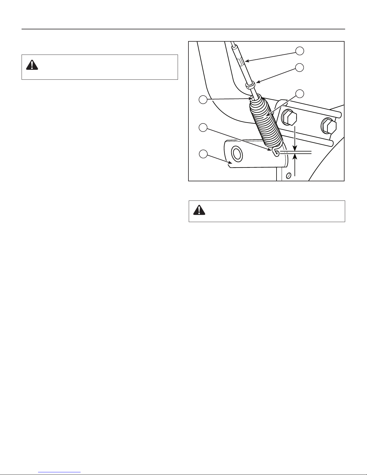
1. With the auger control lever released, the hook (A, Figure 14)
should barely touch the lever (B) without raising it. There can
be a maximum of 1/32 in. (0.8 mm) clearance.
2. To adjust, loosen the nut (C) by holding the adjusting ats (D)
and turning the nut. Then, turn the adjusting ats and hold
the adjustment screw (E). The adjustment screw is a phillips
screw and the head can be held or turned by inserting a
screwdriver through the spring (F).
3. Hold the adjusting ats and tighten the nut.
4. Start the engine and check the auger. The auger must not be
engaged unless the auger control lever is depressed.
5. With the engine running, fully depress the auger drive control
lever. The auger should engage and run normally.
D
C
F
E
A
1/32”
B
Figure 14
(0.8mm)
WARNING: The auger must stop within 5 seconds.
If it does not, see an authorized dealer.
6. Release the auger control lever.
7. If the auger does not operate properly, stop the engine and
recheck the auger control cable adjustment.
8. If the drive linkage is properly adjusted, the tension of the
auger drive belt may require an adjustment. See an authorized
dealer.
20
Page 21
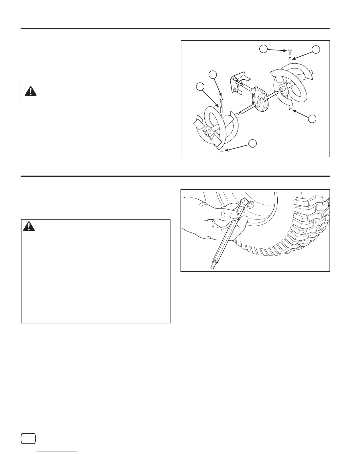
AUGER SHEAR BOLT REPLACEMENT
The augers are secured to the auger shaft with special bolts that
are designed to break if an object becomes lodged in the auger
housing. Use of a harder bolt will reduce the protection provided
by the shear bolt.
Maintenance
A
A
B
WARNING: To ensure safety and performance
levels, only original replacement shear bolts
should be used.
1. Stop the engine, disengage all controls, disconnect the spark
plug lead wire, and make sure all moving parts have stopped.
2. Align the hole in the auger with the hole in the auger shaft. In-
stall new shear bolt (A, Figure 15), spacer (B) and locknut (C)
found in the parts bag or toolbox located on the belt cover.
NOTE: The spacer ts into the larger hole in the auger tube.
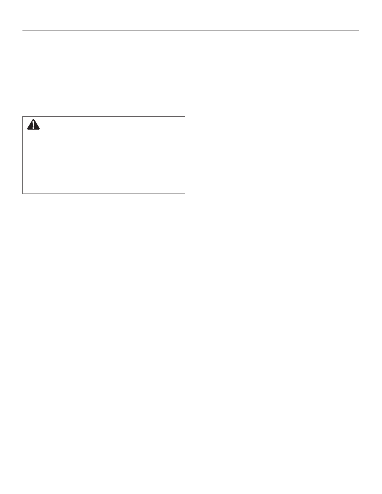
CHECK THE TIRES
Check tires for damage. Check the air pressure in the tires with an
accurate gauge (see Figure 16).
CAUTION: Avoid Injury! Explosive separation of
tire and rim parts is possible when they are ser-
viced incorrectly.
• Do not attempt to mount a tire without the proper
equipment and experience to perform the job.
• Do not inate the tires above the maximum
pressure.
• Do not weld or heat a wheel and tire assembly.
Heat can cause an increase in air pressure
resulting in an explosion. Welding can
structurally weaken or deform the wheel.
• Do not stand in front or over the tire assembly
when inating. Use appropriate tool that allows
you to stand to one side.
B
C
C
Figure 15
Figure 16
NOTICE: Check side of tire for maximum tire pressure. DO
NOT exceed maximum.
en
21
Page 22
Maintenance
OFF-SEASON STORAGE
If the unit will be stored for thirty (30) days or more at the end of
the season, the following steps are recommended to prepare it
for storage. Always refer to the operator’s manual for important
details if the unit is to be stored for an extended period.
NOTE: Fuel must be removed or treated to prevent gum
deposits from forming in the tank, lter, hose, and carburetor
during storage.
DANGER: Fire and Explosion Hazard
Gasoline is highly ammable and its vapors
are explosive. Fumes may travel to a distant
ignition source and an explosion and/or re
may result.
Handle gasoline carefully. Never store the unit,
with fuel in the tank, indoors or in a poorly
ventilated enclosure where fuel fumes could
reach an open ame, spark, pilot light, such as
a furnace, water heater, or clothes dryer.
• Thoroughly clean the unit.
• Lubricate all lubrication points (see authorized dealer).
• Make sure all nuts, bolts, and screws are securely fastened.
Inspect all visible moving parts for damage, breakage, and
wear. Replace if necessary.
• Touch up all rusted or chipped paint surfaces; sand lightly
before painting.
• Cover the bare metal parts of the snowthrower housing
auger, and the impeller with rust preventative.
• If possible, store your unit indoors and cover it to give
protection from dust and dirt.
• If the machine must be stored outdoors, cover with a heavy
tarpaulin.
To Return to Service:
• Fill the fuel tank with a fresh fuel.
• Make sure all fasteners are tight.
• Make sure all guards, shields, and covers are in place.
22
Page 23

PROBLEM LOOK FOR REMEDY
Auger does not stop
within 5 seconds after
right control lever is
released.
Discharge chute or
deector does not work
(electric).
Discharge chute or
deector does not work
(remote-manual).
Engine fails to start. Key is o. Push key in to the ON position.
Engine starts hard or
runs poorly.
Excessive vibration. Loose parts or damaged
Free-Hand™ control is
ACTIVE.
Free-Hand™ control is
not working correctly (fails
Safety Test 3).
Auger control cable out of
adjustment (fails Safety
Test 1).
Auger belt guide out of
adjustment.
Electrical failure. See authorized dealer.
Discharge chute
or deector out of
adjustment or needs
lubrication.
Failure to prime a cold
engine.
Fuel shut-o valve is
CLOSED position (if
equipped).
Out of fuel. Fill fuel tank.
Choke OFF - cold engine. Turn choke ON, set throttle to FAST.
Engine ooded. Turn choke to OFF; try starting.
No spark. See authorized dealer.
Water in fuel, or old fuel. Drain tank. (Dispose of fuel at an authorized hazardous waste
Cord not plugged in or
malfunctions (Electric
Start models).
Fuel mixture too rich. Move choke to OFF position.
Spark plug faulty, fouled,
or gapped incorrectly.
Fuel cap vent is blocked. Clear vent.
impeller/auger.
Release both auger control and traction/Free-Hand™ control
levers to stop auger.
See authorized dealer.
Adjust auger control cable. Refer to “Auger Control Cable
Adjustment” in the Maintenance section of this manual. Make
sure auger control passes Safety Test 1.
See authorized dealer.
See authorized dealer.
Press primer button twice and start.
Turn valve to OPEN position.
facility.) Fill with fresh fuel.
Plug in cord or replace defective cord.
See authorized dealer.
Stop engine immediately. See authorized dealer.
Troubleshooting
en
23
Page 24

Troubleshooting
PROBLEM LOOK FOR REMEDY
Snowthrower forward
and reverse motion
does not stop when
traction control lever is
released.
Snowthrower veers to
one side.
Scraper bar does not
clean hard surface.
Snowthrower fails to
move at slow speeds.
Snowthrower fails
to move forward or
reverse at any speed.
Unit fails to discharge
snow.
Traction control out of
adjustment (fails Safety
Test 2).
Tire pressure not equal. Check tire pressure.
One wheel is set in freewheeling mode. (Traction
lock pin is in the OUTER
hole.) Models with wheel
pins or locks.
Skid shoes improperly
adjusted.
Traction control out of
adjustment.
Drive belt loose or
damaged.
Traction control out of
adjustment.
Worn or damaged friction
disc.
Auger control cable out of
adjustment.
Auger drive belt loose or
damaged.
Broken shear bolt. Replace shear bolt. Refer to “Auger Shear Bolt Replacement” in
Discharge chute clogged
with snow.
Foreign object lodged in
auger.
See authorized dealer.
Make sure the left traction lock pin is in the INNER holes (to
engage the traction drive).
Adjust skid shoes as needed.
Move speed select lever one speed faster. If that doesn’t work, see
authorized dealer.
See authorized dealer.
See authorized dealer.
See authorized dealer.
Adjust auger control cable. Refer to “Auger Control Cable
Adjustment” in the Maintenance section of this manual.
See authorized dealer.
the Maintenance section of this manual.
Stop engine immediately. Always use the clean-out tool to clear a
clogged discharge chute, not your hands. Clean discharge chute
and inside of auger housing. Refer to “Warnings” in Operator
Safety section.
Stop engine immediately. Always use the clean-out tool to clear a
clogged chute, not your hands. Remove object from auger. Refer
to “Warnings” in Operator Safety section.
24
Page 25

Warranties
Craftsman Limited Warranty
General: Craftsman products are warranted to be free from defects in materials or workmanship for a specic time period as set-out below (the “Warranty Period”). Warranties extend to the original purchaser of a Craftsman product only.
Purchases made through an online auction or through any website other than www.sears.ca are excluded. The relevant
Warranty Period commences on the original date of purchase. Within this period, Sears Canada, Inc. will, at its sole op-
tion, repair or replace any products or components which fail in normal use. Such repairs or replacement will be made at no
charge to the customer for parts or labor, provided that the customer shall be responsible for any transportation cost.
Exclusions: This warranty does not cover failures due to normal wear, abuse, misuse, neglect (including but not limited to
the use of stale fuel, dirt, abrasives, moisture, rust, corrosion, or any adverse reaction due to improper storage or use habits), improper maintenance or failure to follow maintenance guidelines and/or instructions, failure to operate the product in
accordance with the owner’s manual or any additional instructions or information provided at the time of purchase or in subsequent communications with the original purchaser, accident or unauthorized alterations or repairs made or attempted by
others. Also excluded from warranty coverage – except as provided below - are the following: maintenance, adjustments,
components subject to wear including but not limited to: cosmetic components, belts, blades, blade adapters, bulbs, tires,
lters, guide bars, lubricants, seats, grips, recoil assemblies, saw chains and bars, trimmer lines and spools, spark plugs,
starter ropers and tines, and discoloration resulting from ultraviolet light. Any product missing the model and/or serial num-
ber identication label will be disqualied from coverage under this warranty.
Repairs: Repairs have a 90 day warranty. If the defective product is still within the Warranty Period, then the new warranty
is 90 days from the date of repair or to the end of the original Warranty Period, whichever period is longer.
Disclaimers: THE WARRANTIES AND REMEDIES CONTAINED HEREIN ARE EXCLUSIVE AND IN LIEU OF ALL
OTHER WARRANTIES, WHETHER ORAL OR WRITTEN (OTHER THAN AS STATED HEREIN), AND WHETHER EXPRESS, IMPLIED OR STATUTORY, INCLUDING BUT NOT LIMITED TO ANY. THIS WARRANTY GIVES YOU SPECIFIC
LEGAL RIGHTS, WHICH MAY VARY FROM PROVINCE TO PROVINCE.
IN NO EVENT SHALL SEARS BE LIABLE FOR ANY INCIDENTAL, SPECIAL, INDIRECT OR CONSEQUENTIAL DAMAGES, WHETHER RESULTING FROM THE USE, MISUSE OR INABILITY TO USE THE PRODUCT OR FROM DEFECTS
IN THE PRODUCT. THE EXCLUSIONS IN THIS PARAGRAPH SHALL NOT APPLY IN JURISDICATIONS WHERE APPLICABLE LAW DOES NOT ALLOW FOR THE EXCLUSION OF INCIDENTAL OR CONSEQUENTIAL DAMAGES. IN
SUCH JURISDICTIONS, THIS PARAGRAPH SHALL NOT APPLY, BUT THE REMAINING PROVISIONS OF THIS DOCUMENT SHALL REMAIN VALID.
Sears retains the exclusive right to repair or replace the product or oer a full refund of the purchase price at its sole discretion. SUCH REMEDY SHALL BE YOUR SOLE AND EXCLUSIVE REMEDY FOR ANY BREACH OF WARRANTY.
Customer Responsibilities: In additional to complying with all suggested maintenance guidelines and instructions, customers’ obligations shall include but shall not be limited to: operating the product in accordance with the owner’s manual
or any additional instructions or information provided at the time of purchase or in subsequent communications to the purchaser from time to time, exhibit reasonable care in the use, operation, maintenance, general upkeep and storage of the
product. Failure to comply with these requirements will void any applicable warranty.
List of Applicable Warranty Periods: The following list contains the applicable Warranty Period for your Craftsman prod-
uct and is based on a combination of the type of product or component and the intended and actual use of the product or
component:
1. 90 days: Craftsman products intended for use or actually used for commercial, institutional, professional or income-
producing purposes.
2. 2 years: Craftsman riding lawn mowers, yard and garden tractors, walk behind mowers, tillers, brush cutters, snow
blowers, handheld blowers, backpack blowers, hedge trimmers and electrical products for noncommercial, nonprofes-
sional, non-institutional, or non-income-producing use, except for those components which are part of engine systems
manufactured by third party engine manufacturers for which the purchase has received an separate warranty with
product information supplied at the time of purchase.
en
25
Page 26

Warranties
3. 1 year: Craftsman power cutters, stump grinders, pole pruners, gas chain saws, electric chain saws, trimmer attach-
ments, baggers and pole saws for noncommercial, nonprofessional, non-institutional, or non-income-producing use.
4. 90 days: All defective batteries, which will be replaced during this 90-day Warranty Period.
5. 60 days: Additional Warranty Period of 60 days will apply to adjustments and worn products or components BUT
DOES NOT INCLUDE WEAR OR ADJUSTMENTS for products used for commercial, institutional, professional or in-
come-producing purposes. Wear items include but are not limited to: belts, blades, tires, spark plugs, air lters,
chains, shear bolts, skid plates, scraper bars, drift cutters, ropes, tines, collection bags and pulleys.
As the Warranty Period runs from the date of purchase and NOT from the date that a product is delivered, opened, assembled or rst used, please ensure during this time period that your product or component has been assembled and tested for
correction operation regardless of when you intend to actually use it. Claims made after the Warranty Period has expired
will not be honored.
Proof of Purchase/Documentation: Warranty coverage is conditioned upon the original purchaser furnishing Sears Canada or its authorized third party service provider if applicable, with the original sales receipt or other adequate written proof
of the original purchase date and identication of the product. In the event that the original purchaser is unable to provide
a company of the original sales receipt, Sears Canada Inc. reserves the right to determine in its sole discretion what other
written proof of the original purchase date and identication of the product is acceptable.
Revision: 03/13/2009
Maintenance Agreement
The Craftsman Warranty plus a Maintenance Agreement, provide maximum value for Sears products. Contact your nearest
Sears store for details.
26
Page 27
en
27
Page 28

Specications
ENGINE:
Brand Briggs & Stratton®
Model Series Professional Series
Gross Torque 11.5 T.P. @ 3060 rpm
Type 4-Cycle - OHV
Displacement 15.26 cu in. (250 cc)
Starting System Recoil, 110V Electric w/Cord
Alternator 9 Amp Reg
Spark Plug Gap 0.030 in. (0,76 mm)
Oil Capacity 20 oz (0,59 liters)
Engine Oil Mineral 5W30
Fuel Tank Volume Nylon 3.2 qts (3,0 liters)
Ignition System This spark ignition system complies
with Canadian standard ICES-002.
AUGER/IMPELLER:
Clearing Width 24.0 in. (61 cm)
Intake Height 19.75 in. (50,2 cm)
Auger/Impeller Diameter 12.0 in. (30,5 cm)
Number of Impeller Blades 3
TM
CHUTE:
Chute Deector Electric
Chute Rotation Electric 200°
DRIVE SYSTEM:
Drive Type Friction Disc - PRO Easy-Turn
Drive Speeds 6 Forward Speeds, 2 Reverse
Tire Size 16 x 4.8 in. (41 x 12 cm)
Tire Ination See the sidewall of the tire for proper ination.
TM
Power Rating
The gross power rating for individual gasoline engine models is labeled in accordance with SAE (Society of Automotive Engi-
neers) code J1940 Small Engine Power & Torque Rating Procedure, and is rated in accordance with SAE J1995. Torque values
are derived at 2600 RPM for those engines with “rpm” called out on the label and 3060 RPM for all others; horsepower values are
derived at 3600 RPM. The gross power curves can be viewed at www.BRIGGSandSTRATTON.COM. Net power values are taken
with exhaust and air cleaner installed whereas gross power values are collected without these attachments. Actual gross engine
power will be higher than net engine power and is aected by, among other things, ambient operating conditions and engine-to-
engine variability. Given the wide array of products on which engines are placed, the gasoline engine may not develop the rated
gross power when used in a given piece of power equipment. This dierence is due to a variety of factors including, but not limited
to, the variety of engine components (air cleaner, exhaust, charging, cooling, carburetor, fuel pump, etc.), application limitations,
ambient operating conditions (temperature, humidity, altitude), and engine-to-engine variability. Due to manufacturing and capacity limitations, Briggs & Stratton may substitute an engine of higher rated power for this engine.
28
Page 29

Repair Parts
PTS - 1
Page 30

Handles & Controls Group
NOTE: Unless noted otherwise,
use the standard hardware torque
specification chart.
CRAFTSMAN 24" C950-52301-0
PTS - 2
Page 31

Handles & Controls Group
PART NO. DESCRIPTIONREF NO QTY.
CRAFTSMAN 24" C950-52301-0
CAPSCREW, Hex Head, 3/8-16 x 2, GR5 0010 1923701SM 1
SPRING, 1/2 Dia. x 3/4 0050 50786MA 1
WASHER, 3/8 x 13/16 OD 0060 1918266SM 1
NUT, Hex Lock, ESNA Light, 3/8-16 0070 1919439SM 1
LEVER, Clutch, LH 0080 1739782AYP 1
SPEED LEVER ASSEMBLY 0100 1736836YP 1
CAPSCREW, Hex Head, 1/4-20 x 1-3/4, GR5 0120 1921962SM 6
BRACKET, Controls 0130 1737684YP 1
ROD, Speed Select 0140 1737331YP 1
NUT, Hex Flange Whiz Lock Small, 5/16-18 0150 1931277SM 3
NUT, Hex, 5/16-24 0170 2820263SM 2
BALL JOINT, Quick Release 0190 1739290YP 1
WIRING HARNESS 0230 1752981YP 1
* FUSE, Mini, 10 Amp 0230-10 ----- 1
HARNESS, Heated Hand Grip, ON/OFF 0233 1752164YP 1
NUT, Hex Nylock Flange, 1/4-20 0235 5025391SM 3
NUT, Hex Lock, ESNA Light, 1/4-20 0300 1920397SM 4
BRACKET, Light 0320 1753046YP 2
SCREW, Torx, 1/4-20 x 5/8 0325 880845YP 2
CONTROL PANEL ASSEMBLY 0330 1753269BTYP 1
SCREW, Pan Head Torx, Taptite, 1/4-20 x 3/4 0340 1960556SM 4
BOLT, Shoulder, Hex Washer Head, 1/4 x 1-9/32 0360 1750554YP 2
BOLT, Carriage, 5/16-18 x 3/4 0370 340720MA 3
SUPPORT, Dash 0390 1739500AYP 1
CABLE, Steering Control 0395 1737510YP 2
CABLE, Auger Drive 0400 1737544YP 1
LEVER, Clutch, RH 0410 1739783AYP 1
NUT, Hex Lock, Nylon Insert, 10-24 0420 1933896SM 2
HAND GRIP, Heated 1" Dia. x 5-1/4 Lg 0430 1738124YP 2
SCREW, 1/8-20 x 1/8 0435 703044 4
SPACER, Stepped 0440 1736542YP 2
SCREW, #10C x 1-1/2 0445 7073145YP 2
SPACER, 17/64 ID x 3/8 OD x 11/32 Lg 0450 1678392SM 2
BRACE, Shift 0460 1737552YP 1
HANDLE, Upper, Right 0470 1737531AYP 1
HANDLE, Upper, Left 0480 1737532AYP 1
BOLT, Carriage, Locking, 5/16-18 x 2-1/4 0490 1750299YP 2
HANDLE, Lower 0500 1737274AYP 1
KNOB, Wing, 5/16-18 0510 7035744YP 4
WASHER, Locking, Internal Teeth, 5/16 0515 7090391SM 4
LIGHT, Halogen 0520 762343MA 1
BOLT, Carriage, 5/16-18 x 3/4, G5 0530 1737687YP 4
NUT, Hex KEPS, Conical Washer, 5/16-18 0535 1960684SM 4
Footnotes
Note* See your local hardware store for replacement bulbs and fuses.
PTS - 3
Page 32

Handles & Controls Group
NOTE: Unless noted otherwise,
use the standard hardware torque
specification chart.
CRAFTSMAN 24" C950-52301-0
PTS - 4
Page 33

Handles & Controls Group
PART NO. DESCRIPTIONREF NO QTY.
CRAFTSMAN 24" C950-52301-0
CABLE, Traction Drive 0560 1737511YP 1
BRACKET, Pivot, Free Hand 0590 1733505ASM 1
SPACER, Powdered Metal 0600 1733095SM 1
ROD & SPRING ASSEMBLY 0610 1736363YP 1
SPRING, Compression, 017/32 ID x 2-1/4 Lg 0630 2108360SM 1
BRACKET, Mounting, Dash, R.H. 0640 1739663AYP 1
ROD, Hold Down, 5/32 Dia., 5-5/8 Lg 0650 1736360YP 1
CABLE TIE, 7" 0670 7012080SM 5
KNOB, Slot Speed 0680 1733192SM 1
WASHER, 1/4 x 5/8 OD 0700 1921319SM 6
TIE, Self Locking 0720 1737275YP 1
SCREW, Round Head Phillips, #10-24 x 3/4 0750 1960589SM 1
NUT, Hex Lock, Nylon, #10C 0760 7091290SM 1
SCREW, Hex Washer Head, Taptite, 1/4-20 x 3/4 0780 1925592SM 1
BOLT, Carriage, 5/16-18 x 1-3/4, G5 0790 1931338SM 1
BOLT, Carriage, Short Neck, 1/4-20 x 3/4, G5 0930 7091530SM 1
SWITCH, Heated Hand Grip 0970 1752242YP 1
BRACKET, HHG Switch 0980 1739861AYP 1
POD, Chute Rotation, RH 1010 1739483AYP 1
POD, Deflector Control, LH 1020 1739484AYP 1
SCREW, Pan Head Torx, Taptite, 1/4-20 x 3/4 1030 1960556SM 5
BRACKET, Dash Mounting, LH 1080 1739664AYP 1
Footnotes
Note* See your local hardware store for replacement bulbs and fuses.
PTS - 5
Page 34

Engine & Frame Group
NOTE: Unless noted otherwise,
use the standard hardware torque
specification chart.
CRAFTSMAN 24" C950-52301-0
PTS - 6
Page 35

Engine & Frame Group
PART NO. DESCRIPTIONREF NO QTY.
CRAFTSMAN 24" C950-52301-0
* ENGINE, 11.5TP Briggs & Stratton (Engine Model: 15C114-0153-F8) 0010 15C114-0153-F8 1
CAP, Fuel 0010-10 792647 1
GUARD, Muffler (Incl. Ref. No. 0010-30) 0010-20 797003 1
SCREW, Tapping, Hex Washer Head 0010-30 810214 3
CORD, Electric 0020 6219MA 1
CAPSCREW, Hex Head, Trilobular, 3/8-16 x 1-1/4 0050 75246GS 4
PULLEY ASSEMBLY 0080 1737509YP 1
LOCKWASHER, Spring 5/16 0100 703116 1
CAPSCREW, Hex Head, 5/16-24 x 1-3/4, G8 0110 1750393YP 1
KEY, Parallel 0115 2157427SM 1
V-BELT, Multi Speed 0120 1737220YP 1
PULLEY ASSEMBLY 0125 1733968YP 1
BELT, Auger, V4L 38.10 MF 05-10B 0130 585416MA 1
STOP, Belt 0140 1737377YP 1
NUT, Hex KEPS, Conical Washer, 5/16-18 0170 1960684SM 1
BOLT, Carriage, 5/16-18 x 1 G5 0171 1931335SM 1
WASHER, 1/4 x 1-1/4 x 1/16 0176 1960151SM 1
SPACER, Powdered Metal 0177 1733095SM 1
BELLCRANK 0178 1737329YP 1
BRACKET, Lower 0179 1737328AYP 1
BRACKET, Support, Auger Idler 0180 1737297YP 1
BRACKET, Guide Wheel 0190 1737347AYP 1
CAPSCREW, Hex Head, 1/4-20 x 1-1/2 G5 0191 1922837SM 1
SPOOL CABLE, Auger Control 0192 579860MA 1
NUT, Lock, Serrated, 1/4-20 0193 192432GS 2
IDLER, Plastic, Ball Bearing 0200 1502120MA 1
NUT, Hex Jam, 3/8-16 0210 1960251SM 1
BOLT, Carriage, 3/8-16 x 1-1/4 0220 585781MA 1
WASHER, Thrust 0225 1670971SM 1
IDLER, Auger 0230 1737296YP 1
WASHER, 1/2” Flat 0250 1960027SM 2
BRACKET & HUB ASSEMBLY, Spring 0260 1733451SM 1
PIN, Hair 0270 0031X6MA 2
PIN, Clevis 0280 1736381YP 1
PANEL, Bottom 0290 1737221AYP 1
SCREW, Hex Washer Head Taptite, 1/4-20 x 5/8 0300 1927429SM 7
SPRING, Torsional 0310 1737350YP 1
FRAME BOX 0320 1737106ZYP 1
PLATE, Engine Mount 0330 1754138ZYP 1
SCREW, Hex Washer Head Taptite, 5/16-18 x 3/4 0350 1664847SM 19
COVER, Belt 0360 1750551YP 1
SCREW, Hex Washer Head, SEMS, Taptite, 1/4-20 x 3/4 0370 1751355YP 2
COTTER PIN, 1/4" Self Locking 0420 7023590SM 1
Footnotes
Note* To verify your specific engine model, please reference the ID Tag located on your engine. See your local Briggs &
Stratton distributor for parts and service.
PTS - 7
Page 36

Auger Drive Group
NOTE: Unless noted otherwise,
use the standard hardware torque
specification chart.
CRAFTSMAN 24" C950-52301-0
PTS - 8
Page 37

Auger Drive Group
PART NO. DESCRIPTIONREF NO QTY.
CRAFTSMAN 24" C950-52301-0
GEAR CASE ASSEMBLY 0070 704363 1
KEY, Square, 3/16 x 3/4 0080 2001022MA 1
IMPELLER 0090 1739094AYP 1
HUB, Impeller 0100 1739073YP 1
SCREW, Hex Washer Head, Taptite, 5/16-18 x 5/8 0110 1930601SM 3
SET SCREW, Socket Head, 5/16-18 x 1/2 0130 7090848SM 3
PULLEY 0150 1501211MA 1
CAPSCREW, Hex Head, 1/4-20 x 1-3/4 0160 9524MA 2
NUT, Hex Center Lock, 1/4-20 0170 73826MA 2
SPACER, Sleeve, 1/4 x 1/2 0190 3943MA 2
AUGER, LH, 24" (Includes Ref. No. 0220-40) 0220 1738299BTYP 1
AUGER, RH, 24" (Includes Ref. No. 0220-40) 0230 1738300BTYP 1
FITTING, Grease 0220-40 10104MA 1
KIT, Shear Bolt (Includes Ref. Nos. 0160, 0170 & 0190) -- 1501216MA 1
Footnotes
PTS - 9
Page 38

Auger Housing Group
NOTE: Unless noted otherwise,
use the standard hardware torque
specification chart.
CRAFTSMAN 24" C950-52301-0
PTS - 10
Page 39

Auger Housing Group
PART NO. DESCRIPTIONREF NO QTY.
CRAFTSMAN 24" C950-52301-0
HOUSING, Auger, 24" 0010 1687773YP 1
CLAMP 0020 1736620YP 2
SCREW, Truss Head Torx, #10-24 x 3/8 0030 1960569SM 2
NUT, Nylock, 10 x 24 0040 15X146MA 2
BRUSH, Cleanout 0060 1736094YP 1
BEARING, Auger Shaft 0070 53757MA 2
CAPSCREW, Hex Washer Head, Taptite, 5/16-18 x 3/4 0080 1664847SM 4
BOLT, Carriage, Short Neck, 3/8-16 x 1-1/4, GR5 0090 7091790YP 4
NUT, Hex Flange, 3/8-16 0100 7091619SM 4
NUT, Hex Flange, Serrated Lock, 5/16-18 0110 710026MA 7
SKID, Height Adjust 0150 1750222YP 2
BLADE, Scraper, 24" 0160 1738335AYP 1
RETAINER, Ball Bearing 0170 1756809YP 1
BEARING, Ball 0180 1705897SM 1
CAPSCREW, Hex Head, 5/16-18 x 5/8 0190 001X45MA 3
PLUG, Panel 0200 760040MA 2
BOLT, Carriage, 5/16-18 x 5/8, G5 0210 7090799SM 4
DRIFT CUTTER 0220 1733102ASM 2
BOLT, Carriage, 5/16-18 x 3/4 0230 340720MA 2
NUT, Wing, 5/16-18 0240 711604MA 2
Footnotes
PTS - 11
Page 40

Traction Drive Group
NOTE: Unless noted otherwise,
use the standard hardware torque
specification chart.
CRAFTSMAN 24" C950-52301-0
PTS - 12
Page 41

Traction Drive Group
PART NO. DESCRIPTIONREF NO QTY.
CRAFTSMAN 24" C950-52301-0
* TRANSMISSION, General Transmission H2 0200 1733972YP 1
BRACKET 0210 1737267AYP 2
CAPSCREW, Hex Head, 3/8C x 2-3/4 GR5 0220 7091557SM 4
NUT, Hex Jam, 3/8-16 0230 1960251SM 4
ROD, Speed Select 0240 1737330YP 1
COTTER PIN, 1/4" Self Locking 0250 7023590SM 2
TUBE, Support 0260 1737310YP 1
GEAR, Drive 0300 1737311YP 2
AXLE 0310 1737309YP 2
NUT, Hex Flange, Whiz Lock Large, 3/8-16 0320 1928352SM 4
RETAINER, Bearing 0330 1736396YP 2
BEARING, Ball 0340 53263MA 2
RING, Retaining 0350 1737742YP 2
RETAINER, Bolt 3/8" 0355 7013847YP 4
SCREW, Hex Washer Head Taptite, 5/16-18 X 3/4 0420 1664847SM 4
BOLT, Carriage, FH GR 5, 3/8-16 x 3/4 0430 1737686YP 4
WASHER, Flat, 3/8 0450 703184 2
Footnotes
Note* See Transmission Assembly Group for detailed service parts.
PTS - 13
Page 42

Transmission SERVICE PARTS - General Transmission H2
NOTE: Unless noted otherwise,
use the standard hardware torque
specification chart.
CRAFTSMAN 24" C950-52301-0
PTS - 14
Page 43

Transmission SERVICE PARTS - General Transmission H2
PART NO. DESCRIPTIONREF NO QTY.
TRANSMISSION, Complete General Transmission H2 0200 1733972YP 1
SPRING, Traction, 8.75 Inches 0200-1 1739646YP 2
SCREW, 5 X 25 0200-2 1739645YP 1
WASHER, 5.3 X 15 X 1.2.ipt 0200-3 1739641YP 1
LEVER 0200-4 1739642YP 1
CAM, Control 0200-5 1739644YP 1
SPRING, Variator 0200-6 1739640YP 1
SHIFT ARM 0200-7 1739625YP 1
PULLEY ASSEMBLY 0200-8 1739624YP 1
SCREW, M8x20 left 0200-9 1739622YP 1
WASHER, 25 X 35 X 1.5 0200-10 1739636YP 1
BEARING, 6005 2RS 0200-11 1739639YP 1
GEAR 0200-12 1739648YP 2
RETAINER 0200-13 1739647YP 2
WASHER, 0.8 X 27 X 3 0200-14 1739623YP 1
SCREW, 4 X 16 0200-15 1739643YP 4
NUT 0200-16 1739626YP 2
BOLT, Allen-Head, CHC M5 X 1.2 0200-17 1739629YP 2
PIN 0200-18 1739632YP 2
WASHER, Starlock 0200-19 1739634YP 4
CRAFTSMAN 24" C950-52301-0
Footnotes
PTS - 15
Page 44

Wheels & Tires Group
NOTE: Unless noted otherwise,
use the standard hardware torque
specification chart.
CRAFTSMAN 24" C950-52301-0
PTS - 16
Page 45

Wheels & Tires Group
PART NO. DESCRIPTIONREF NO QTY.
CRAFTSMAN 24" C950-52301-0
WHEEL & TIRE ASSEMBLY, 4.80-8, LH (Includes Ref. 0010-20) 0010 1754243YP 1
WHEEL & TIRE ASSEMBLY, 4.80-8, RH (Includes Ref. 0010-20) 0020 1754245YP 1
VALVE STEM & CAP 0010-20 2172353SM 1
BOLT, Hex, 1/4-20 x 1-3/4, G5 0060 577015MA 2
NUT, Hex, Nylock, 1/4-20 0070 15X145MA 2
Footnotes
PTS - 17
Page 46

Decals Group
NOTE: Unless noted otherwise,
use the standard hardware torque
specification chart.
CRAFTSMAN 24" C950-52301-0
PTS - 18
Page 47

Decals Group
PART NO. DESCRIPTIONREF NO QTY.
CRAFTSMAN 24" C950-52301-0
DECAL, Danger Chute, FR/ENG 0040 1737865YP 1
DECAL, Danger Foot, FR/ENG 0050 1737866YP 1
DECAL, Auger Control Symbols 0060 1737869YP 1
DECAL, Traction Control Symbols 0070 1737870YP 1
DECAL, Handle Operation 0080 1754679YP 1
DECAL, Gear Shift 0095 1751582YP 1
DECAL, Do Not Shift 0330 1755585YP 1
DECAL, 1150/24 0340 704353 1
DECAL, Craftsman, Rear Stripe 0350 1750853YP 1
DECAL, Hood Stripe 0360 1750850YP 1
Footnotes
PTS - 19
Page 48

Discharge Chute Group
NOTE: Unless noted otherwise,
use the standard hardware torque
specification chart.
CRAFTSMAN 24" C950-52301-0
PTS - 20
Page 49

Discharge Chute Group
PART NO. DESCRIPTIONREF NO QTY.
CRAFTSMAN 24" C950-52301-0
PINION 0010 1728967SM 1
SCREW, Torx Button Head, M5 x .8 x 14 0030 1739621YP 3
WASHER, Flat, 1/4 0035 7091552SM 3
SCREW, Hex Washer Head, Taptite, 1/4-20 x 3/4 0040 1925592SM 1
COVER, Electric Chute Rotation 0050 1737455YP 1
RETAINER, Spout 0060 7011938SM 3
SCREW, Hex Washer Head, Plastite, 10-14 x 5/8 0070 1960001SM 6
SWITCH, Chute Rotation 0090 1737378YP 1
DECAL, Hinge 0150 1733601SM 2
CHUTE 0160 1738045ZYP 1
MOTOR, Spout Rotator 0200 1739309YP 1
GEAR 0230 1737465AYP 1
ADAPTER, Chute Ring 0240 1737411YP 1
BOLT, Carriage, 1/4-20 x 3/4 0250 703101 7
NUT, Hex Flange, ESNA, 1/4-20 0260 2860694SM 7
BRACKET, Weld Stud 0290 1738267BMYP 1
MOTOR, Chute Deflector 0300 1737941YP 1
SCREW, Truss Head Torx, 1/4-20 x 3/4 0310 1960715SM 2
NUT, Hex Flange, ESNA, 1/4-20 0320 1960694SM 2
SWITCH / COVER 0330 1737379YP 1
WASHER, Rubber 0340 1738244YP 1
NUT, Left Handed 0350 1738245YP 1
WASHER, Flat, 1/4 0360 71067MA 1
Footnotes
PTS - 21
Page 50

15C114--0151--F8
48 SHORT BLOCK
847
287
742
746
1036 EMISSIONS LABEL
523
842
524
18
1058 OPERATOR’S MANUAL
584
585
684
227
562
505
12
1329 REPLACEMENT ENGINE
1
718
552
2
3
15
1330 REPAIR MANUAL
616
615
307A
306
307
998
1427
219
220
22
25
29
27
32
20
26
28
27
21
46
16
24
741
377
332
MSC000678- 2 Assemblies include all parts shown in frames. 09/16/2013
22
Page 51

15C114--0151--F8
REF. PART REF. PART REF. PART
NO. NO. DESCRIPTION NO. NO. DESCRIPTION NO. NO. DESCRIPTION
1 794188 Cylinder Assembly
2 796961 Kit--Bushing/Seal
(Magneto Side)
3 299819s Seal--Oil
(Magneto Side)
12 699485 Gasket--Crankcase
15 691686 Plug--Oil Drain
16 797070 Crankshaft
18 699804 Cover--Crankcase
20 692550 Seal--Oil
(PTO Side)
21 281658s Cap--Oil Fill
22 799318 Screw
(Crankcase
Cover/Sump)
24 796335 Key--Flywheel
(Steel)
25 791786 Piston Assembly
(Standard)
-- -- -- -- -- -- -- N o t e -- -- -- -- -791791 Piston
Assembly
(.020” Oversize)
26 791787 Ring Set
(Standard)
-- -- -- -- -- -- -- N o t e -- -- -- -- -791792 Ring Set
(.020” Oversize)
27 690975 Lock--Piston Pin
28 690229 Pin--Piston
29 791783 Rod--Connecting
32 791784 Screw
(Connecting Rod)
46 693404 Camshaft
48 N/A Short Block
(Not Available
At This Printing)
219 693578 Gear--Governor
220 691724 Washer
(Governor Gear)
227 794367 Lever--
Governor Control
287 699629 Screw
(Dipstick Tube)
306 695710 Shield--Cylinder
307 699483 Screw
(Cylinder Shield)
(M4x11.1mm)
307A 790557 Screw
(Cylinder Shield)
(M4x16.6mm)
332 792723 Nut
(Flywheel)
377 690979 Key--Woodruff
505 691251 Nut
(Governor
Control Lever)
523 798469 Dipstick
524 281370s Seal--Dipstick Tube
552 692346 Bushing--
Governor Crank
562 691119 Bolt
(Governor
Control Lever)
584 791759 Cover--
Breather Passage
585 791760
615 692576 Retainer--
616 692547 Crank--Governor
684 793369 Screw
718 592860 Pin--Locating
741 695087 Gear--Timing
742 692564 Retainer--E Ring
746 790278 Gear--Idler
842 795015 Seal--O Ring
847 798468 Dipstick/Tube
998 696683 Pipe--Oil
1036 Label--Emissions
1058
279128TRI Operator’s Manual
1329 N/A Replacement Engine
1330 272147 Repair Manual
1427 695757 Cap--Pipe
Gasket-Breather Passage
Governor Shaft
(Breather
Passage Cover)
(Dipstick Tube)
Assembly
(Available from a
Briggs & Stratton
Authorized Dealer)
(Not Available
At This Printing)
Carburetor Overhaul Kit -- Reference 121
Engine Gasket Set -- Reference 358
MSC000678- 3 Assemblies include all parts shown in frames. 09/16/2013
Valve Gasket Set -- Reference 1095
23
Page 52

15C114--0151--F8
337
1026
635
5
34
238
36
40
33
40
45
155
35
238
1022
1023
1022
1029
192
830
914A
914
619
122
1034
993
7
869
13
51A
51A
MSC000678- 4 Assemblies include all parts shown in frames. 09/16/2013
24
Page 53

15C114--0151--F8
REF. PART REF. PART REF. PART
NO. NO. DESCRIPTION NO. NO. DESCRIPTION NO. NO. DESCRIPTION
5 791720 Head--Cylinder
7 791716 Gasket--Cylinder Head
13 699482 Screw
(Cylinder Head)
33 499642 Valve--Exhaust
34 795443 Valve--Intake
35 691304 Spring--Valve
(Intake)
36 691304 Spring--Valve
(Exhaust)
40 692194 Retainer--Valve
45 690977 Tappet--Valve
51A 791718 Gasket--Intake
122 791717 Spacer--Carburetor
155 797442 Plate--Cylinder Head
192 797440 Adjuster--Rocker Arm
238 691300 Cap--Valve
337 691043 Plug--Spark
619 699481 Screw
(Cylinder Head Plate)
635 692076 Boot--Spark Plug
830 797441 Stud--Rocker Arm
869 691155 Seat--Valve
914 699481 Screw
(Rocker Cover)
(M6x15.8mm)
914A 797444 Screw
(Rocker Cover)
M6x9.5mm)
993 694088 Gasket--
Cylinder Head Plate
1022 691890 Gasket--Rocker Cover
1023 499924 Cover--Rocker Arm
1026 790287 Rod--Push
1029 797443 Arm--Rocker
1034 691343 Guide--Push Rod
Carburetor Overhaul Kit -- Reference 121
Engine Gasket Set -- Reference 358
MSC000678- 5 Assemblies include all parts shown in frames. 09/16/2013
Valve Gasket Set -- Reference 1095
25
Page 54

15C114--0151--F8
125
51A
187
51
95
130
528
97
127
133
104
692
975
137
105
276
98
108
318
472
209
109
365
122
51A
51A
187A
601
601
117
118
276
276
972
957
190
MSC000678- 6 Assemblies include all parts shown in frames. 09/16/2013
26
Page 55

15C114--0151--F8
REF. PART REF. PART REF. PART
NO. NO. DESCRIPTION NO. NO. DESCRIPTION NO. NO. DESCRIPTION
51 791718 Gasket--Intake
51A 791718 Gasket--Intake
95 691636 Screw
(Throttle Valve)
97 797628 Shaft--Throttle
98 797156 Kit--Idle Speed
104 797622 Pin--Float Hinge
105 797139 Valve--Float Needle
108 796993 Valve--Choke
109 791954 Shaft--Choke
117 590906 Jet--Main
(Standard)
118 590440 Jet--Main
(High Altitude)
(5000/9000 Feet)
122 791717 Spacer--Carburetor
125 590907 Carburetor
127 797633 Plug--Welch
130 797630 Valve--Throttle
133 797136 Float--Carburetor
137 798932 Gasket--Float Bowl
187 798907 Line--Fuel
(Formed)
187A 791766 Line--Fuel
(Cut to
required length)
190 699220 Screw
(Fuel Tank)
209 693206 Spring--Governor
(Yellow)
276 797632 Washer--Sealing
318 798649 Screw
(Mounting Bracket)
365 699484 Screw
(Carburetor)
472 791948 Knob--Choke Shaft
528 793006 Hose--Primer
601 791850 Clamp--Hose
(Green)
692 797624 Spring--Detent
957 799719 Cap--Fuel Tank
972 799863 Tank--Fuel
975 798931 Bowl--Float
Carburetor Overhaul Kit -- Reference 121
Engine Gasket Set -- Reference 358
MSC000678- 7 Assemblies include all parts shown in frames. 09/16/2013
Valve Gasket Set -- Reference 1095
27
Page 56

15C114--0151--F8
333
222
190
209
608
632
188
1230
851
334
635
474
1119
458
58
578
592
501
526
493A
65A
309
735
813318
697
727
1054
732
MSC000678- 8 Assemblies include all parts shown in frames. 09/16/2013
28
Page 57

15C114--0151--F8
REF. PART REF. PART REF. PART
NO. NO. DESCRIPTION NO. NO. DESCRIPTION NO. NO. DESCRIPTION
58 693389 Rope--Starter
65A 690837 Screw
(Rewind Starter)
(#10--32x.27mm)
188 699479 Screw
(Control Bracket)
190 699220 Screw
(Fuel Tank)
209 693206 Spring--Governor
(Yellow)
222 793100 Bracket--Control
309 798884 Motor--Starter
318 798649 Screw
(Mounting Bracket)
333 796964 Armature--Magneto
334 699477 Screw
(Magneto Armature)
458 699334 Kit--Rope/Handle
474 698314 Alternator
493A 691117 Bracket--Mounting
501 698315 Regulator
526 690297 Screw
(Regulator)
578 791956 Wire Assembly
592 690800 Nut
(Rewind Starter)
608 797430 Starter--Rewind
632 692653 Spring/Link--
Mechanical Governor
635 692076 Boot--Spark Plug
697 795012 Screw
(Starter Motor)
727 698039 Cover--Starter Drive
732 699200 Screw
(Starter Drive Cover)
735 795901 Cord--Starter
813 690635 Clamp
851 493880s Terminal--Spark Plug
1054 280275 Tie--Cable
1119 699772 Screw
(Alternator)
1230 699847 Stud
(Control Bracket)
Carburetor Overhaul Kit -- Reference 121
Engine Gasket Set -- Reference 358
MSC000678- 9 Assemblies include all parts shown in frames. 09/16/2013
Valve Gasket Set -- Reference 1095
29
Page 58

15C114--0151--F8
731A
976
1196A
731
1196
892
23
990
663
11
493
318
610
528
163
281
604
564
604A
332
455
304
65
1005
1070
37
78
832
300
1251
1251A
1252
1252A
836
883
613
305
MSC000678- 10 Assemblies include all parts shown in frames. 09/16/2013
30
Page 59

15C114--0151--F8
REF. PART REF. PART REF. PART
NO. NO. DESCRIPTION NO. NO. DESCRIPTION NO. NO. DESCRIPTION
11 695745 Tube--Breather
23 798882 Flywheel
37 699661 Guard--Flywheel
65 699228 Screw
(Rewind Starter)
(M5x6.3mm)
78 699205 Screw
(Flywheel Guard)
163 696024 Gasket--Air Cleaner
281 793122 Panel--Control
300 798173 Muffler
304 699598 Housing--Blower
305 699481 Screw
(Blower Housing)
318 798649 Screw
(Mounting Bracket)
332 792723 Nut
(Flywheel)
455 797431 Cup--Flywheel
493 695744 Bracket--Mounting
528 845267 Hose--Primer
564 699854 Screw
(Control Cover)
604 790473 Cover--Control
604A 793134 Cover--Control
610 794614 Arrestor--Intake
613 791972 Screw
(Muffler)
663 699854 Screw
(Control Panel)
731 794589 Hood--Snow
731A 793643 Hood--Snow
832 797003 Guard--Muffler
836 699854 Screw
(Muffler Guard)
883 691893 Gasket--Exhaust
892 791944 Switch--Key
976 793382 Primer--Carburetor
990 794696 Key Set
1005 794273 Fan--Flywheel
1070 699201 Screw
(Flywheel Fan)
1196 699854 Screw
(Snow Hood)
(M5x10.8mm)
1196A 798785 Screw
(Snow Hood)
(#10--24x.65)
1251 796421 Shield--Snow
1251A 790556 Shield--Snow
1252 699234 Screw
(Snow Shield)
(M5x11.1mm)
1252A 699491 Screw
(Snow Shield)
(M6x11mm)
Carburetor Overhaul Kit -- Reference 121
Engine Gasket Set -- Reference 358
MSC000678- 11 Assemblies include all parts shown in frames. 09/16/2013
Valve Gasket Set -- Reference 1095
31
Page 60

15C114--0151--F8
121 CARBURETOR OVERHAUL KIT
104
51
51A
3
12
7
20
127A
134
137A
358 ENGINE GASKET SET
51
51A
163
163A
163
585
276A
633
633A
883
993
1022
1095 VALVE GASKET SET
51
7
585
51A
993
1022
MSC000678- 12 Assemblies include all parts shown in frames. 09/16/2013
32
Page 61

15C114--0151--F8
REF. PART REF. PART REF. PART
NO. NO. DESCRIPTION NO. NO. DESCRIPTION NO. NO. DESCRIPTION
3 299819s Seal--Oil
(Magneto Side)
7 698210 Gasket--Cylinder Head
12 699485 Gasket--Crankcase
20 692550 Seal--Oil
(PTO Side)
51 692555 Gasket--Intake
51A 791718 Gasket--Intake
104 797622 Pin--Float Hinge
121 792006 Kit--
Carburetor Overhaul
127A 691739 Plug--Welch
134 398188 Kit--Needle/Seat
137A 798932 Gasket--Float Bowl
163 696024 Gasket--Air Cleaner
276A 271716 Washer--Sealing
358 791797 Gasket Set--Engine
585 791760 Gasket--
Breather Passage
633 691321 Seal--
Choke/Thottle Shaft
633A 693867 Seal--
Choke/Thottle Shaft
883 691893 Gasket--Exhaust
993 694088 Gasket--
Cylinder Head Plate
1022 691890 Gasket--Rocker Cover
1095 791798 Gasket Set--Valve
Carburetor Overhaul Kit -- Reference 121
Engine Gasket Set -- Reference 358
MSC000678- 13 Assemblies include all parts shown in frames. 09/16/2013
Valve Gasket Set -- Reference 1095
33
Page 62

PTS - 34
Page 63

Manual de l’opérateur
Modèle n° C950-52301-0
Soueuse à neige mono-étagée,
11,5 couple de puissance, 24 pouces
MISE EN GARDE : Avant d’utiliser ce produit, lire le manuel et suivre
toutes ses consignes de sécurité et ses instructions d’utilisation.
Sears Canada Inc., Toronto, Ontario M5B 2C3
Consulter le site Web de Craftsman : www.sears.ca/craftsman
Page 64

Merci d’avoir acheté cette soueuse à neige CRAFTSMAN. Nous sommes heureux que vous ayez placé votre conance
dans la marque CRAFTSMAN. Si vous utilisez et entretenez ce produit CRAFTSMAN conformément aux instructions du
manuel, vous pourrez l’utiliser pendant de nombreuses années.
Ce manuel contient des informations relatives à la sécurité an que vous connaissiez les dangers et risques qui sont
liés aux soueuses à neige et la façon de les éviter. Cette soueuse à neige est conçue et est destiné uniquement
pour éliminer la neige et ne peut être utilisée pour aucune autre raison. Il est important que vous lisiez et compreniez
ces instructions en profondeur avant de tenter de démarrer ou d’utiliser l’équipement. Un assemblage de nition est
nécessaire avant d’utiliser la soueuse à neige. Veuillez vous reporter à la rubrique Assemblage an d’obtenir les
directives pour l’assemblage de nition. Veuillez suivre attentivement les directives. Sauvegardez ces instructions pour
votre référence.
Soueuse à neige:
Numéro de modèle ______________________________
Révision _____
Numéro de série ______________________________
Moteur:
Numéro de modèle
Révision
______________________________
_____
Numéro de série ______________________________
Date d’achat: ______________________________
Adresse du magasin d’achat: ______________________________
Ville: ______________________________
Province: ______________________________
Téléphone: ______________________________
REMARQUE: Noter les renseignements ci--dessous pour l’identication de la machine en cas de perte ou de vol.
2
Page 65

Table des matières
Sécurité de l’utilisateur ................................................................. 4
Symboles de risque et leur signification ..........................................4
Symboles de contrôle sur l’équipement ...........................................4
Symboles d’alerte de sécurité et mots-indicateurs ..........................5
Autocollants de sécurité ..................................................................9
Fonctions et commandes ............................................................. 10
Commandes de la souffleuse à neige ...........................................10
Commandes du moteur .................................................................11
Fontionnement .............................................................................. 12
Avant d’utilisation souffleuse à neige .............................................12
Tests du système sécurité .............................................................12
Utilisation de la souffleuse à neige ................................................12
Arrêter la souffleuse à neige ..........................................................13
Commande de traction Easy Turn™ .............................................13
Contrôler le niveau d’huile (avant de démarrer le moteur) ............14
Recommandations concernant le carburant ..................................14
Haute altitude ................................................................................14
Plein d’essence .............................................................................15
Démarrage du moteur ...................................................................15
Arrêt le moteur ...............................................................................16
Dégagement de l’éjecteur bloqué .................................................17
Conseils d’fontionnement ..............................................................17
Entretien ........................................................................................ 18
Tableau de maintenance ...............................................................18
Contrôle des émissions .................................................................18
Entretien du moteur ......................................................................18
Réglage de la hauteur des patins .................................................19
Réglage du câble de commande de la tarière ...............................20
Remplacement du boulon de cisaillement pour tarière .................21
Vérication des pneus ...................................................................21
Remisage hors saison ...................................................................22
Dépannage ..................................................................................... 23
Garanties ........................................................................................ 25
Spécifications ................................................................................ 28
fr
3
Page 66

Sécurité de l’utilisateur
Symboles de risque et leur signification
Feux
Impulseur
rotatif
Choc
Surface
chaude
Tarière
rotative
Distance
de sécurité
Pièces
tournantes
Engrenages
rotatifs
Symboles de contrôle sur l’équipement
Huile
Carburant
Arrêt
carburant
Starter en
position
Arrêt
Starter en
position
Marche
Arrêt
Lent
Rapide
Tarière
d’embrayage
Marche
avant
Neutre
Marche
arrière
STOP
Moteur
Marche-
Arrêt
Starter-
Marche
Amorceur
de moteur
Moteur en
marche
Moteur à
l’arrêt
Objets
projetés
Explosion
Vapeurs
toxiques
Protection
des oreilles
Commande
de traction
Commande
de la tarière
Démarreur
électrique
Protection
des yeux
Pièces
amovibles
Eet de
recul
Produits
chimiques
dangereux
Conduit
d’éjecteur
Déecteur
de goulotte
Poignées
chauantes
Blocage
de roue
1
Commande de traction
Commande Free-Hand™
Easy-Turn™
4
REMARQUE : Les symboles de commande illustrés sur
cette page n’apparaîtront pas tous sur votre soueuge
à neige. Voir la section Fonctions et commandes pour
les symboles qui s’appliquent.
2
Page 67

Symboles d’alerte de sécurité et mots-indicateurs
Le symbole d’alerte de sécurité et mot de signalisation
(DANGER, AVERTISSEMENT, MISE EN GARDE ou AVIS) sont
utilisés pour indiquer la probabilité ou potentiel de la gravité de
blessure corporelle et/ou dommage au produit. En plus, un
symbole de danger peut être utilisé pour représenter un type de
danger.
DANGER indique un danger qui, si non évité, résultera à la
mort ou blessure grave.
AVERTISSEMENT indique un danger qui, si non évité, peut
résulter à la mort ou blessure grave.
MISE EN GARDE indique un danger qui, si non évité, peut
résulter à une blessure mineure.
AVIS indique une situation pouvant endommager le pro-
duit.
AVERTISSEMENT
Certains composants de ce produit et de ses accessoires contiennent des produits chimiques reconnus par l’État de Californie
comme étant cause de cancer, d’anomalies congénitales ou
d’autres effets néfastes sur la fonction de reproduction. Se net-
toyer les mains après la manipulation.
Sécurité de l’utilisateur
AVERTISSEMENT
Lisez, comprenez et suivez toutes les instructions sur la souffleuse à neige dans le manuel
de l’opérateur avant de faire fonctionner cette
machine.
La faillite d’observer les instructions de sécurité
dans ce manuel peut résulter à la mort ou une
blessure grave.
• Familiarisez-vous bien avec les commandes et l’utilisation appropriée de la soueuse à neige.
• Assurez-vous de vous être convenablement entraîné avant
d’utiliser la soueuse à neige.
• Sachez comment arrêter l’appareil et déclencher les com-
mandes rapidement.
• Ne permettez jamais à quiconque d’utiliser la soueuse à
neige sans avoir reçu d’instruction appropriée.
• Suivez toujours les instructions du manuel de l’utilisateur au
cas où la soueuse de neige aurait été remisée pendant une
période prolongée.
• Veuillez maintenir ou remplacer les étiquettes de sécurité et
d’instructions si nécessaire.
• Ne tentez jamais de faire des réparations majeures sur la
soueuse à neige à moins d’avoir été convenablement formé
pour le faire. L’entretien inadéquat de la soueuse à neige
peut résulter à un fonctionnement dangeureux, dommage à
l’équipement et l’invalidation de la garantie du produit.
AVERTISSEMENT
L’échappement du moteur de cet appareil contient des produits
chimiques connus selon l’État de la Californie de causer le
cancer, des anomalies congénitales ou autre effet nuisible à la
reproduction.
AVERTISSEMENT
• Mettre les mains en contact avec la turbine à l’intérieur de la
goulotte d’éjection est la cause la plus commune d’accidents
corporels associés aux soueuses à neige.
• Cette soueuse à neige est capable d’amputer les mains ou
les pieds et de projeter des objets. Lisez et observez toutes les
instructions de sécurité dans ce manuel. Ne pas s’y conformer
peut entraîner de sérieuses blessures, voire la mort.
DANGER
Le conduit d’éjection contient un impulseur
rotatif pour éjecter la neige. Ne débouchez ou
ne dégagez jamais le conduit d’éjection avec
vos mains. Les doigts peuvent facilement être
prises dans l’impulseur. Utilisez toujours un
outil de nettoyage.
La faillite d’observer ces instructions de sécurité résultera à une amputation traumatique ou
dilacératon grave.
fr
5
Page 68

Sécurité de l’utilisateur
AVERTISSEMENT
Gardez les mains, les pieds et les vêtements
loin des pièces rotatives. Les pièces rotatives
peuvent contacter ou enchevêtrer les mains,
les pieds, les cheveux, les vêtements ou ac-
cessoires.
La faillite d’observer ces instructions de sécu-
rité résultera à une amputation traumatique ou
dilacératon grave.
• Toutes les fois que vous nettoyez, réparez ou inspectez la
soueuse à neige, assurez-vous que le moteur soit ARRÊTÉ,
que le câble de la bougie soit débranché et que toutes les
pièces mobiles soit arrêtées.
• Ne mettez ni les mains ni les pieds près ou en dessous des
pièces tournantes. Toujours se tenir à l’écart de l’ouverture
d’éjection.
• N’utilisez jamais la soueuse à neige sans que les protections adéquates et tous les autres dispositifs de sécurité ne
soient en place et en état de marche.
• Ne laissez jamais la soueuse à neige sans surveillance pendant que le moteur tourne. Toujours débrayer les commandes
de tarière et de traction, arrêter le moteur et retirer les clés.
• Gardez tout vêtement ample éloigné du devant de la soueuse à neige et de la tarière. Les foulards, les mitaines, les cordons pendantes, les vêtements lâches et pantalons peuvent
rapidement être prises dans le dispositif rotatif et une amputation se produira. Attachez les cheveux longs et enlevez les
bijoux.
• Faites tourner la machine quelques minutes après avoir
déblayé la neige pour empêcher le collecteur ou la turbine de
geler.
• Débrayez le collecteur ou la turbine quand la soueuse à
neige est transportée ou n’est pas utilisée.
AVERTISSEMENT
Les objets peuvent être ramassés par la
tarière et projetés du conduit. Ne rejetez
jamais de la neige vers des spectateurs et ne
permettez à personne de se placer devant
la soueuse à neige. La faillite d’observer
ces instructions de sécurité dans ce manuel
résultera à la mort ou blessure grave.
• Portez toujours des lunettes de sécurité ou des masques de
protection pendant l’utilisation et lors de réglages ou de réparations.
• Soyez attentif de la direction d’où la neige est éjectée. Les
piétons tous près, les animaux domestiques ou les propriétés
peuvent être endommagés par la projection des objets.
• Soyez conscient de votre environnement lors de l’utilisation
de la soueuse à neige. Ne passez pas par-dessus des éléments tels que du gravier, des tapis, des journaux, des jouets
ou des roches cachées sous la neige, dans la mesure où ils
peuvent être tous rejetés par la goulotte ou se bloquer dans la
tarière.
• Soyez très prudent lors du fonctionnement sur ou traversant
les voies d’accès, les trottoirs ou les routes de gravel.
• Ajustez la hauteur du boîtier de collection pour dégager le
gravel ou toutes autres matières rocheuses.
• N’utilisez jamais la soueuse à neige près d’enceintes vi-
trées, d’automobiles, de puits de fenêtre, de fossés et de tout
ce qui peut s’y comparer, sans avoir procédé à un réglage
adéquat de l’inclinaison de la goulotte d’éjection.
• Familiarisez-vous avec la zone dans laquelle vous prévoyez
d’utiliser la soueuse à neige. Marquez les bornes des voies
d’accès et des trottoirs.
AVERTISSEMENT
Des accidents tragiques peuvent se produire
lorsque l’opérateur n’est pas averti de la
présence d’enfants. Les enfants sont souvent
attirés par la machine et le soufflage de neige.
Ne supposez jamais que les enfants resteront
là où vous les avez vus pour la dernière fois.
• Gardez les enfants éloignés de la zone pendant l’utilisation.
Les enfants sont souvent attirés par l’équipement. Soyez at-
tentif des personnes présentes.
• Faire preuve de vigilance et arrêter la machine si des enfants
pénètrent dans la zone.
• Ne jamais laisser les enfants se servir de la machine.
• Prenez bien soin lorsque vous approché des coins sans visibilités, les arbustes, les arbres ou les autres objets qui vous
cachent la vue. Les enfants peuvent être présents.
AVERTISSEMENT
Les moteurs émettent du monoxyde de carbone, un gaz toxique sans odeur ni couleur.
Respirer du monoxyde de carbone peut provoquer des nausées, des évanouissements, voire
même la mort.
• Démarrez et faites tourner le moteur à l’extérieur.
• Ne faites pas fonctionner le moteur dans un endroit enfermé,
même si les portes ou les fenêtres sont ouvertes.
6
Page 69

Sécurité de l’utilisateur
AVERTISSEMENT
Le carburant et ses vapeurs sont extrêmement
inflammables et explosifs. Veuillez bien prendre
soin avec précaution du carburant.
Le fait de ne pas observer ces instructions
de sécurité peut être cause d’incendie ou
d’explosion entraînant de graves brûlures, voire
la mort.
LORS DE L’ADDITION DU CARBURANT
• Arrêtez le moteur et laissez refroidir pour au moins 2 minutes
avant d’enlever le bouchon de réservoir pour ajouter le carburant.
• Remplissez le réservoir de carburant dehors ou dans un en-
droit bien ventilé.
• Ne remplissez pas trop le réservoir de carburant. Pour permettre l’expansion de l’essence, ne remplissez pas au-dessus
le bas du cou du réservoir de carburant.
• Gardez le carburant loin des étincelles, des ammes nues, des
lampes témoins, de chaleur et d’autres sources d’allumage.
• Vériez souvent les lignes de carburant, le bouchon et les accessoires pour ssures et fuites. Remplacez si nécessaire.
• Utilisez un réservoir de carburant approuvé.
• Si le carburant renverse, attendez jusqu’à ce qu’il soit va-
porisé avant de mettre en marche le moteur.
MISE EN MARCHE DU MOTEUR
• Assurez-vous que la bougie d’allumage, le silencieux, le
bouchon de carburant et ltre à air (si équippé) sont en place
et bien xés.
• Lorsque la bougie d’allumage est enlevée, ne mettez pas en
marche le moteur.
• Si du carburant se répand, ne tentez pas de démarrer le
moteur, mais éloignez la soueuse à neige de la zone du
déversement et évitez de créer toute source d’inammation
jusqu’à ce que les vapeurs de carburant se soient dissipées.
• N’amorcez pas trop le moteur. Suivez les instructions dans ce
manuel pour mettre le moteur en marche.
• Si le moteur est noyé, veuillez régler le volet de départ (si
équippé) à la position OUVERT / MARCHE, déménager
l’accélateur (si équippé) à la position RAPIDE et mettre en
marche le moteur.
LORS DU FONCTIONNEMENT D’ÉQUIPEMENT
• N’inclinez pas la soueuse à neige à un angle qui cause le
carburant de renverser.
• N’étouez pas le carburateur pour arrêter le moteur.
• Si l’assemblage d’épurateur (si équippé) ou le ltre à air est
enlevé, veuillez ne pas mettre en marche le moteur.
LORS DU CHANGEMENT D’HUILE
• Si vous écoulez l’huile du dessus du tube d’huile de remplis-
sage, le réservoir de carburant doit être vide ou le carburant
peut s’écouler et peut résulter en feux ou explosion.
LORS DE LA TRANSPORTATION D’ÉQUIPEMENT
• Transportez lorsque le réservoir est VIDE, ou lorsque la soup-
ape d’arrêt est fermée.
AVEC LE CARBURANT DANS LE RÉSERVOIR
• Entreposez loin des fournaises, des poêles, des chaue-eaux
ou autres appareils qui ont une amme d’allumage ou autre
source d’allumage qui peut allumer les vapeurs de carburant.
AVERTISSEMENT
Le fonctionnement sans danger de la souffleuse à neige demande un soin et entretien
vigilant.
• Débrayer toutes les manettes et passer au point mort avant de
démarrer le moteur peut être cause de dommages corporels.
• Laissez le moteur s’ajuster à la température extérieure avant
de commencer de déblayer la neige.
• Utilisez un branchement à trois ls avec mise à la terre pour
toutes les soueuses à neige équipées de moteur à traction
électrique ou de moteur à démarrage électrique.
AVERTISSEMENT
La mise en marche du moteur créée une gerbe
d’étincelles.
L’étencelle peut mettre le feu au gaz inflammable tout près.
Explosion et feu peu en résulter.
• Si il y a une fuite de pétrole liquéé PL dans l’endroit où vous
êtes, n’essayez pas de mettre le moteur en marche.
• N’utilisez pas des uides sous pression à cause des vapeurs
sont inammables.
AVERTISSEMENT
La mise en marche du moteur produit de la
chaleur. Les pièces du moteur, en particulier le
silencieux, devient extrèmement chaud.
Ne pas observer ces instruction de sécurité
peut résulter à des brûlures thermiques graves
au contact.
• Ne touchez jamais un moteur ou un silencieux chaud. Laissez le silencieux, le cylindre de moteur et les ailettes refroidir
avant de toucher.
• Enlevez tous débris de la section du silencieux et de la section
du cylindre.
• Veuillez installer et entretenir en bon état le pare-étincelles
avant d’utiliser l’équipement sur une terre brute de couverture
de forêt, de gazon ou de brousse.
• L’utilisation ou le fonctionnement du moteur sur des terrains
forestiers, broussailleux ou herbeux constituent une violation de la Section 4442 du Code des ressources publiques
de Californie, à moins que le système d’échappement ne soit
équipé d’un pare-étincelles maintenu en bon état de marche,
comme le dénit la Section 4442. D’autres états ou juridictions fédérales peuvent avoir des lois similaires. Contactez le
fabriquant, détaillant ou revendeur d’origine de l’équipement
pour obtenir un pare-étincelles conçu pour le système
d’échappement installé sur ce moteur.
fr
7
Page 70

Sécurité de l’utilisateur
AVERTISSEMENT
Cette souffleuse à neige doit être proprement
entretenue pour assurer un fonctionnement et
une performance en toute sécurité. La faillite
d’observer les instructions de sécurité dans ce
manuel peut résulter à la mort ou une blessure
grave.
• Lors de tout entretien ou réparation sur la soueuse à neige,
coupez le moteur, débranchez le l de bougie et gardez-le
éloigné de la bougie pour empêcher quiconque de démarrer
accidentellement le moteur.
• Vériez à intervalles fréquents que les boulons de cisaillement
et la visserie soient convenablement serrés.
• Gardez les écrous et les boulons serrés et gardez la soueuse à neige en bon état.
• Ne touchez pas les dispositifs de sécurité. Vérier régulière-
ment leur bon fonctionnement et réparer le cas échéant.
• Les composants sont sujets à s’user, s’endommager et à
se détériorer. Vériez fréquemment les composants et remplacez les pièces recommandés au besoin.
• Vérifiez la commande de fonctionnement fréquemment.
Ajuster et réparer le cas échéant.
• Lors de réparations, utilisez uniquement des pièces de rechange d’origine homologuées ou identiques.
• Conformez toujours avec les spécications du fabricant sur
tous les réglages et ajustements.
• Utilisez uniquement des accessoires homologués par le
fabricant ou identiques, comme par exemple les masses
d’équilibrage, les contrepoids ou les modules de conduite).
• N’essayez jamais de faire des ajustements pendant que le
moteur est en marche (à l’exception de la recommendation
spécique du fabricant).
AVERTISSEMENT
Cette souffleuse à neige est aussi sûre que
son utilisateur puisse l’être. Si mal utilisé ou
mal entretenu, ceci peut être dangereux.
Souvenez-vous que vous êtes responsable
pour votre sécurité et de ceux près de vous.
• Maintenez la zone d’intervention débarrassée de toutes personnes, en particulier des petits enfants et des animaux domestiques.
• Inspectez attentivement la zone où la soueuse à neige sera
utilisée et retirez tous les tapis, luges, planches, ls de fer et
autres objets inopportuns.
• N’utilisez pas la soueuse à neige sans porter de vêtements
d’hiver adéquats.
• Portez des chaussures permettant d’avoir une meilleure prise
sur les surfaces glissantes.
• Faites preuve de prudence pour éviter de glisser ou de
tomber lorsque vous faites fonctionner la soueuse à neige
en marche arrière.
• N’utilisez jamais la soueuse à neige sans bonne visibilité ou
éclairage. Toujours garder un bon équilibre et tenir fermement
les poignées.
• Ne déblayez pas la neige de la surface des pentes. Utilisez
une précaution extrême lors du changement de direction sur
les pentes. Ne pas tenter de déblayer des pentes raides.
• Ne surchargez pas la capacité de la machine en essayant de
déblayer la neige trop vite.
• N’utilisez jamais la soueuse à neige à des vitesses de déplacement élevées sur des surfaces glissantes. Regardez
derrière la soueuse à neige et faites preuve de prudence
lors des marches arrière.
• N’utilisez pas la soueuse à neige sur des surfaces suré-
levées comme les toits de résidence, de garage, de véranda
ou de toute autre structure ou bâtiment comparable.
• Les utilisateurs devraient évaluer leur capacité à utiliser la
soueuse à neige de manière susamment sûre pour éviter
de se blesser soi-même ou autrui.
• La soueuse à neige est destinée à déblayer uniquement la
neige. N’utilisez pas la soueuse à neige pour toute autre rai-
son.
• Ne transportez pas des passagers.
• Après avoir heurté un objet étranger, COUPEZ le moteur, débranchez le cordon d’alimentation des moteurs électriques,
inspectez attentivement la soueuse à neige pour détecter
d’éventuels dégâts et réparez-les avant de redémarrer et
d’utiliser la soueuse à neige.
• Si la soueuse à neige vibre anormalement, COUPEZ le
moteur. Toute vibration est généralement un avertissement
de problème. Veuillez voir un concessionnaire agéé pour de
réparation nécessaire.
• Pour des modèles munis avec des moteurs de démarrage
électrique, débranchez le cordon d’alimentation après que le
moteur est mis en marche.
8
Page 71

Autocollantes de sécurité
Sécurité de l’utilisateur
Avant de mettre en marche votre soueuse à neige, lisez
les étiquettes autocollantes de sécurité sur votre soueuse
à neige. Les précautions et les avertissements sont pour
votre sécurité. Pour éviter des blessures personels ou du
dommage à votre soueuse à neige, veuillez comprendre
et suivre les directives de sécurité sur les décalcomanies.
Pièce No. 1754679
Décal. Tableau de bord
Pièce No. 1751582
Étiquette vitesses
2
1
2
1
Si n’importe quelle décalcomanie de sécurité devient usée
ou endommagée et ne peut être lu, commandez des décal-
comanies de remplacement de votre concessionnaire agréé.
1754679
Pièce No. 1737870
Étiquette de la commande
de traction
Part No. 1737869
Étiquette de la commande de tarière
Pièce No. 278297
Étiquette du moteur
Numéro d’identication du
produit et étiquette du
numéro de série (Arrière
du carter du moteur)
Pièce No. 1737865
Étiquette Danger
de la goulotte
Pièce No. 1737866
Étiquette Danger de
la tarière
Figure 1
fr
9
Page 72

Fonctions et commandes
A
G
E
K
2
2
D
1
1
C
F
J
B
H
1
2
Figure 2
COMMANDES DE LA SOUFFLEUSE À NEIGE
A. Levier de changement de vitesse — Permet à l’utilisateur
de sélectionner les vitesses avant et arrière (voir Figure 2).
Pour changer de vitesse, déplacer le levier à une position
désirée.
REMARQUE : Ne pas déplacer le levier de sélection de
vitesse pendant que la commande de traction est em-
brayée. Ceci peut résulter à un dommage grave au sys-
tème d’entraînement.
B. Levier de commande de la tarière — Utiliser pour em-
brayer et débrayer la tarière et l’impulseur. Pour embrayer,
pousser vers le bas. Pour débrayer, relâcher.
C. Commutateur de la rotation du conduit — Utiliser pour
tourner le conduit d’éjection vers la gauche ou la droite.
D. Commutateur de déecteur de goulotte — Utilisé pour
commander l’angle du déecteur de goulotte (en haut ou en
bas).
10
I
E. Commande de traction Easy Turn™ — Quand elle est em brayée, permet à l’utilisateur de débrayer une roue tractrice
tout en permettant à l’autre roue de continuer à rouler pour fa
ciliter les virages.
F. Free-Hand
commande d’entraînement (gauche) et la commande de
tarière (droite), permet à l’opérateur de relâcher la manette
de commande de tarière pour utiliser d’autres commandes.
G. Levier de commande de traction — Utilisé pour propulser
la soueuse à neige en marche avant ou arrière. Appuyer
pour embrayer, relâcher pour débrayer. Voir également «
Commande Free-Hand ».
H. Outil de nettoyage — Utilisez pour enlever la neige et débris
du conduit d’éjection et du boîtier de tarière.
I. Patins — Utilisés pour régler le dégagement au sol du carter
de tarière.
TM
Commande — Après avoir embrayé la
Page 73

Fonctions et commandes
G
F
B
A
C
E
D
H
STOP
Figure 3
COMMANDES DE LA SOUFFLEUSE À NEIGE (Suite)
J. Phares — Utiliser pour faire fonctionner la soueuse à neige
dans des conditions de pauvre visibilité.
K. Commutateur de poignées chauantes — Utilisé pour
réchauer les poignées (MARCHE/ARRÊT).
COMMANDES DU MOTEUR
A. Bouton de commande du volet de départ — Utiliser pour
faire fonctionner le moteur (voir Figure 3).
B. Bouton de démarrage électrique — Utiliser pour la mise en
marche du moteur en utilisant le démarreur électrique.
C. Bouton d’amorceur — Utiliser pour injecter l’essence dans
le manifold du carburateur pour assurer un départ rapide dans
des températures froides.
D. Clé de sécurité — Doit être inséré pour faire fonctionner le
moteur. Retirez pour arrêter. Ne tournez pas la clé de sécurité.
E. Cordon de démarreur — Utiliser pour mettre en marche le
moteur manuellement.
F. Réservoir de carburant et bouchon — Remplissez le
réservoir à peu près 38 mm (1-1/2 po) dessous le haut du cou
pour permettre l’expansion du carburant.
G. Bouchon d’huile de remplissage (jauge d’huile allongé)
H. Soupape d’arrêt du carburant — Utiliser pour fermer
l’alimentation du carburant pour entreposage hors-saison.
fr
11
Page 74

Fonctionnement
AVANT D’UTILISATION SOUFFLEUSE À NEIGE
Contrôler la visserie. Vérier que toute la visserie est
bien serrée.
Lire le Manuel d’instructions et les Sécurité de
l’opérateur avant d’utiliser la soueuse à neige.
comparer les illustrations avec la soueuse à neige
pour se familiariser avec l’emplacement de ses
commandes et réglages. Conserver ce manuel pour
toute consultation ultérieure.
AVERTISSEMENT: L’utilisation de toute soueuse à neige peut provoquer la projection d’objets dans les yeux et
causer de graves lésions oculaires. Toujours porter des lunettes de sécurité ou autre protection oculaire avant
d’utiliser la soueuse à neige. Nous conseillons le port de lunettes de sécurité standard ou d’un masque de
sécurité Wide Vision par-dessus des lunettes correctrices.
TESTS DU SYSTÈME DE SÉCURITÉ
AVERTISSEMENT
Danger d’amputation
Cette soueuse à neige est équipée de plusieurs
systèmes mécaniques de sécurité conçus pour la sécurité
de l’opérateur pendant qu’il utilise cette machine. Vérier
régulièrement le fonctionnement de ces systèmes en
utilisant la liste des tests du système de sécurité. Si
la machine ne fonctionne pas comme décrit, NE PAS
l’utiliser. Contacter votre revendeur agréé pour une
maintenance immédiate.
Test 1 - Commande de tarière/turbine
Alors que le moteur tourne :
• pousser le levier de commande de tarière vers le bas. (La
tarière/turbine devrait tourner.)
• Relâcher le levier de commande de tarière. (La tarière/
turbine devrait s’arrêter dans les 5 secondes.)
Test 2 - Commande d’entraînement de traction
Pendant que le moteur tourne et que la commande de vitesse
est enclenchée sur la première :
• Pousser le levier de commande d’entraînement de traction
vers le bas. (L’unité devrait se déplacer vers l’avant.)
• Relâcher le levier de commande de traction. (L’unité devrait
s’arrêter.)
Test 3 - Commande Free Hand
Alors que le moteur tourne :
• Embrayer les leviers de commande de tarière et de
traction, puis relâcher le levier de commande de tarière. (Les
deux commandes doivent rester embrayées.)
• Puis relâcher le levier de commande de traction. (Les deux
commandes doivent être relâchées.)
UTILISATION DE LA SOUFFLEUSE À NEIGE
AVERTISSEMENT : Fonctionnement avec cabine
de soueuse à neige. Le vent risque souer les
gaz d’échappement vers l’opérateur. En cas d’odeur
d’échappement, changer le sens de fonctionnement.
AVIS : Ne pas rejeter la neige en direction d’un bâtiment, des
objets enfouis pouvant être jetés avec susamment de force
pour causer des dégâts.
1. Démarrer le moteur du tracteur. Voir Démarrage du moteur
dans cette section.
2. Appuyez sur le commutateur de rotation de goulotte (C,
Figure 2) pour tourner le conduit d’éjection à la droite ou la
gauche.
REMARQUE : Cette soueuse à neige est livrée AVEC DE
L’HUILE dans le moteur. Voir les instructions « Avant de
démarrer le moteur » dans la section Fonctionnement de ce
manuel avant de démarrer le moteur.
AVIS : Avant de la faire fonctionner, assurez-vous que l’espace
devant la soueuse à neige est débarrassé de toute personne
ou d’autres obstacles.
3. Appuyez sur le commutateur du déecteur de goulotte (D)
pour commander l’angle du déecteur de goulotte.
4. Appuyer comp lètement sur le levier de commande de tarière
(B) et le maintenir enfoncé pour to embrayer la rotation de
tarière. Relâcher le levier de commande de tarière débrayera
la tarière à moins que la commande Free-Hand™ n’ait été
activée.
5. Appuyer complètement le levier de commande de traction/
Free-Hand™ (G) et le maintenir enfoncé pour embrayer
l’entraînement de traction et commencer à déplacer la
soueuse à neige. Pour débrayer l’entraînement de traction,
relâcher complètement le levier.
6. Lorsque les DEUX leviers sont appuyés, la commande FreeHand™ est activée. Ceci permet à l’opérateur de relâcher
le levier de commande de tarière an d’utiliser les autres
commandes. La tarière continura à tourner jusqu’à ce que la
commande Free-Hand™ est relâchée.
REMARQUE : Toujours relâcher le levier de commande de traction
avant de déplacer le levier de sélection de vitesses.
7. Utiliser le levier de changement de vitesse (A) pour
sélectionner la vitesse d’entraînement vers l’avant. Régler
le levier de sélection de vitesse sur l’une des positions
suivantes comme le déterminent les conditions de neige :
1-2 Mouillée, lourde, fondue, très profonde
3 Modérée
4-5 Très légère
6 Transport
REMARQUE : Il est recommandé, lors du dégagement de neige
lourde et mouillée, de diminuer la vitesse de déplacement de
l’unité, de maintenir le plein régime et de ne pas essayer de
dégager toute la largeur de l’unité.
8. Appuyez sur l’interrupteur du chaue poignée (K) pour
réchauer les poignées.
9. Pour arrêter d’avancer, relâcher le levier de commande de
traction (G).
10. Pour déplacer la soueuse à neige en marche arrière,
mettre le levier de sélection de vitesse dans la première ou
deuxième position de marche arrière et embrayer le levier de
commande de traction.
12
Page 75

ARRÊTER LA SOUFFLEUSE À NEIGE
1. Relâcher le levier de commande de traction (C, Figure 2).
2. Sortir la clé de sécurité (D, Figure 3).
3. La maintenir hors de portée des enfants.
Fonctionnement
2
2
AVERTISSEMENT : Ne jamais faire tourner le moteur
a l’intérieur ou dans des endroits clos et mal
ventilés. Les gaz d’échappement du moteur
contiennent du MONOXYDE DE CARBONE, un GAZ
INODORE et MORTEL.
• Garder les mains, les pieds, les cheveux et les
vêtements amples à l’écart des pièces en mouvement
du moteur et de la soueuse à neige.
• La température du silencieux et de son voisinage peut
dépasser 66 °C (150 °F). Éviter ces zones.
• NE PAS laisser d’enfants ni de jeunes adolescents
utiliser ni s’approcher de la soueuse à neige
durant la marche.
AVERTISSEMENT : Lire le manuel d’instruction avant
d’utiliser la machine. Une utilisation imprudente de
cette machine peut s’avérer dangereuse.
• Ne jamais utiliser la soueuse à neige sans tous ses
capots, grilles et autres protections en place.
• Ne jamais diriger l’éjection vers des fenêtres ni laisser des
personnes s’approcher de la machine alors que le
moteur est en marche.
• Toujours arrêter le moteur avant de quitter la position de
conduite.
• Débrancher la bougie avant de déboucher le carter de vis
sans n ou la goulotte d’éjection et avant d’eectuer des
réglages ou réparations.
• Avant de quitter la machine, enlever la clé de contact. Pour
réduire le risque de feu, garder la machine propre et
exempte d’éclaboussures d’essence, d’huile et autres débris.
1
1
Figure 4
COMMANDE DE TRACTION EASY-TURN™
Pour tourner plus facilement quand on utilise la soueuse à
neige, serrer le levier Easy-Turn™.
Embrayer le levier Easy-Turn™ libère la traction de la roue
gauche ou droite, mais permet à la roue opposée de continuer à
fonctionner. La Figure 4 montre le levier Easy-Turn gauche embrayé.
Relâcher le levier Easy-Turn™ embraye automatiquement les
deux roues d’entraînement en pleine traction (voir Figure 5).
REMARQUE : la commande Easy-Turn™ sera plus dicile à ac-
tiver avec une charge élevée. Activer le levier avant d’entamer un
virage.
fr
Figure 5
13
Page 76

Fonctionnement
CONTRÔLER LE NIVEAU D’HUILE
(AVANT DE DÉMARRER LE MOTEUR)
REMARQUE : Le moteur est livré d’usine rempli d’huile.
Contrôler le niveau d’huile. Compléter le niveau le cas
échéant.
1. S’assurer que la machine est de niveau. Utiliser une huile
détergente de haute qualité classée « Service SF, SH, SJ,
SL ou plus ».
2. Ouvrir le bouchon-jauge d’huile (A, Figure 6) et l’essuyer avec
un chion propre
3. Remettre le bouchon-jauge d’huile en place et tourner dans
le sens des aiguilles d’une montre pour serrer.
4. Ouvrir le bouchon-jauge d’huile et vérier le niveau d’huile.
REMARQUE : Ne pas vérier le niveau d’huile durant la
marche du moteur.
5. Le cas échéant, ajouter de l’huile jusqu’au repère FULL
(Plein) sur le bouchon-jauge d’huile. Ne pas ajouter trop
d’huile.
6. Bien serrer le bouchon-jauge d’huile après chaque contrôle
du niveau d’huile.
REMARQUE : Par très grand froid, au dessous de -18 °C (0
°F), utiliser une huile moteur 5W30 synthétique pour faciliter le
démarrage.
REMARQUE : L’huile moteur S.A.E. 5W30 peut être utilisée
pour faciliter le démarrage par des températures de -7 à -18
°C (20 à 0 °F). L’huile synthétique 5W30 est utilisable à toutes
températures. NE PAS mélanger l’huile avec l’essence. Voir
les huiles recommandées dans le tableau ci-contre.
Synthétique 5W-30
* Sous 4 °C (40 °F) l’utilisation de SAE 30 résultera à une diculté de
mise en marche.
** Au-dessus 27 °C (80 °F) l’utilisation de 10W-30 peut causer une
augmentation de consomption d’huile. Vériez le niveau d’huile plus
fréquemment.
FULL
A
RECOMMANDATIONS CONCERNANT LE
CARBURANT
Le carburant doit répondre aux critères suivants:
• Essence fraîche, propre, sans plomb.
• Un indice minimum d’octane de 87/87 AKI (91 RON). En
cas d’utilisation en altitude, voir ci-après.
• L’essence contenant jusqu’à 10 % d’éthanol (bioéthanol)
est acceptable.
ATTENTION: ne pas utiliser d’essence non approuvée,
comme la E15 et la E85. Ne pas mélanger d’huile à l’essence
ni modier le moteur pour fonctionner avec des carburants
alternatifs. L’utilisation de carburants non autorisés endo magera le moteur et annulera la garantie moteur.
Pour protéger le système d’admission d’essence contre la
formation de gomme, mélanger un stabilisateur à l’essence.
Voir le stockage. Tous les carburants ne sont pas les mêmes.
En cas de dicultés à démarrer ou de problèmes de fonctionnement, changer de fournisseur ou de marque d’essence.
Ce moteur est certié pour fonctionner à l’essence. Le système de contrôle des émissions de ce moteur est EM (Modications Moteur).
Figure 6
HAUTE ALTITUDE
À des altitudes supérieures à 1524mètres, une essence ayant
un indice minimum de 85 octane/85 AKI (89 RON) est acceptable. Pour rester conforme aux normes d’émissions, un
réglage pour haute altitude est nécessaire. Le fonctionnement
sans eectuer ce réglage entraîne une réduction de la perfor-
mance et une augmentation de la consommation d’essence et
des émissions. Consulter un Réparateur Agréé Briggs & Strat-
ton pour plus d’informations sur le réglage pour haute altitude.
Le fonctionnement du moteur à une altitude inférieure à 762
mètres avec le réglage haute altitude n’est pas recommandé.
14
Page 77

Fonctionnement
PLEIN D’ESSENCE
AVERTISSEMENT
Le combustible et ses vapeurs sont
extrêmement inammables et explosifs.
Un incendie ou une explosion peut entraîner
des blessures très graves ou même la mort.
Pour faire le plein
• Couper le moteur et le laisser refroidir au moins 2 minutes
avant d’ouvrir le bouchon du réservoir.
• Remplir le réservoir de carburant à l’extérieur ou dans
un local extrêmement bien ventilé.
• Ne pas trop remplir le réservoir. Pour permettre la dilatation
du carburant, ne pas remplir plus haut que le bas du col
du réservoir.
• Maintenir le carburant à l’écart des étincelles, des ammes
directes, des veilleuses, de la chaleur et des autres sources
d’étincelles.
• Contrôler que les durites, le réservoir, le bouchon et les
raccords de carburant ne présentent ni ssures ni fuites.
Remplacer si nécessaire.
• Si du carburant a été renversé, attendre son évaporation
complète avant de démarrer le moteur.
DÉMARRAGE DU MOTEUR
Assurez-vous que l’huile est à la marque FULL (Plein) du
bouchon d’huile/jauge. La soueuse à neige est muni avec un CA
démarreur électrique et un démarreur manuel. Avant de mettre
en marche le moteur, assurez-vous de bien lire le renseignement
suivant.
Si le moteur es noyé, réglez le volet de départ à la position
OUVERT/MARCHE et continuez d’essayer de mettre le moteur en
marche.
AVERTISSEMENT : Le démarreur électrique est
muni avec un cordon d’alimentation avec une
che trilaire concu pour fonctionner à partir d’un
CA de maison. Le cordon d’alimentation doit être mis à
la terre en tout temps pour éviter la possibilité de choc
électrique qui peut causer une blessure à
Suivez attentivement les instructions suivent :
Assurez-vous que votre maison a un système trilaire
mis à la terre.
Si vous n’êtes pas certain, demandez un électricien
licencié. Si votre maison n’a pas un système trilaire mis
à la terre, n’utilisez pas un démarreur électrique sous
cette condition.
Si votre maison a un système trilaire mis à la terre
mais une prise de courant trilaire n’est pas disponible
pour connecter le démarreur électrique, ayez une prise
trilaire installée par un électricien licencié.
l’opérateur.
Démarrer le moteur comme suit :
1. Vériez le niveau d’huile. Veuillez voir la section « Contrôler
le niveau d’huile. »
2. Assurez-vous que les commandes d’entraînement de
l’équipement sont débrayées.
3. Insérez la clé de sécurité (A, Figure 7) dans la rainure de
clavette et poussez complètement dans la position MARCHE.
4. Tourner le bouton du starter (B) sur la position CHOKE.
REMARQUE : N’utilisez pas le volet de départ pour commencer le
moteur lorsque qu’il est chaud.
5. Poussez le bouton d’amorceur (C) deux fois.
REMARQUE : Ne pas utiliser l’amorceur pour faire démarrer un
moteur chaud.
REMARQUE : Assurez-vous que le cordon de raccordement
électrique est sortie de la prise de courant.
C
B
A
Figure 7
6. Démarreur à rappel : Tenez fermement le cordon du démarreur
(A, Figure 8). Tirez le cordon du démarreur lentement jusqu’à ce
que la résistance est ressenti, puis tirez rapidement.
AVERTISSEMENT : Une rétraction rapide du
cordon de démarreur (eet de rebond) tirera la
main ou le bras de l’opérateur vers le moteur plus
rapidement que l’on ne peut relâcher le cordon
de démarreur. Des os cassés, des fractures, des
blessures, ou des foulures peuvent en résulter.
Lors du mise en marche du moteur, tirez le
cordon démarreur lentement jusqu’à ce qu’une
résistance est ressenti et puis tirez rapidement
pour éviter un impulsion de retour.
REMARQUE : Si le moteur ne marche pas après les premiers
trois tentatives, consultez un revendeur agréé.
AVERTISSEMENT : Pour connecter le cordon
d’alimentation, connectez toujours le cordon
d’alimentation premièrement au boîtier d’interrupteur
situé sur le moteur et puis branchez l’autre bout dans une
prise trilaire mise à la terre.
AVERTISSEMENT : Pour déconnecter le
cordon d’alimentation, débranchez toujours le
bout branché dans la prise trilaire mise à la terre
premièrement.
fr
A
Figure 8
15
Page 78

Fonctionnement
7. Démarrage électrique : Connecter d’abord la rallonge à
la prise du cordon d’alimentation et ensuite dans une prise
murale. Si un autre cordon de raccordement est nécessaire,
assurez-vous qu’il est trilaire.
AVERTISSEMENT : Si le cordon de
raccordement estendommagé, il doit être
remplacé par le manufacturier (ou son agent
agréé) ou par une personne qualiée pour
éviter le danger.
8. Démarrage électrique : Appuyez le bouton de démarrage
(A, Figure 9). Après la mise en marche du moteur,
déconnectez premièrement le cordon de raccordement de la
prise murale et après de la prise du cordon d’alimentation (B).
A
B
ARRÊT LE MOTEUR
Avant d’arrêter le moteur, laissez-le fonctionner pour quelques
minutes pour sécher l’humidité sur le moteur.
AVERTISSEMENT : L’essence et les vapeurs
sont extrèmement ammables et explosifs.
Un incendie ou une explosion peut provoquer des
brûlures graves voire la mort. N’étouez pas le
carburateur pour arrêter le moteur.
1. Sortir la clé de sécurité (A, Figure 7).
2. La maintenir hors de portée des enfants.
REMARQUE : Ne perdez pas la clé de sécurité. Gardez la clé
de sécurité dans un endroit sûr. Le moteur ne fonctionnera pas
sans la clé de sécurité.
Figure 9
IMPORTANT : Pour prolonger la durée de vie du
démarreur, utiliser des cycles de démarrage courts (cinq
secondes maximum). Attendez une minute entre les
cycles de démarrage.
REMARQUE : Si le moteur ne marche pas après les premiers
trois tentatives, consultez un revendeur agréé.
16
Page 79

Fonctionnement
DÉGAGEMENT DE L’ÉJECTEUR BLOQUÉ
DANGER : Le contact des mains avec l’impulseur
rotatif dans le conduit d’éjection est la cause
la plus commune des blessures associés avec des
soueuses à neige. Ne dégagez ou débloqué jamais le
conduit d’éjection avec vos mains ou pendant la mise
en marche du moteur. Les doigts peuvent facilement
être pris piège et une amputation traumatique ou
dilacération grave en résultera.
• ARRÊTEZ LE MOTEUR !
• Attendez 10 secondes pour être certain que les ailettes
de l’impulseur ont arrêté de tourner.
• Utilisez toujours un outil de nettoyage et pas vos mains.
Un outil de nettoyage (A, Figure 10) est attaché à la poigné ou
au-dessus du boîtier de la tarière. Utilisez l’outil de nettoyage pour
enlever la neige du boîtier de la tarière.
A
CONSEILS DE FONCTIONNEMENT
1. L’enlèvement ecace de la neige est accomplie lorsque la
neige est enlevée immédiatement après la tombé.
2. Pour l’enlèvement complète de la neige, veuillez recouvrir
partiellement la section traitée.
3. La neige devrait être déchargée au sens du vent lorsque
possible.
4. Pour usage normal, baissez les patins à 3 mm (1/8 po) sous
la barre de raclage. Pour des surfaces de neige extrèmement
compacte, les patins peuvent être ajustés plus haut pour
assurer un nettoyage ecace.
5. Sur des surfaces rocheuses ou de gravier, les patins devront
être placés à 32 mm (1-1/4 po) sous la barre de raclage
(veuillez voir « Réglage de la hauteur des patins » dans la
section d’Entretien dans ce manuel). Les pierres et le gravel
ne doivent pas être ramassés et projetés par la machine.
6. Après l’enlèvement de la neige est accomplie, laissez le
moteur reposer pour quelques minutes, pour fondre la neige
et la glace accumulés sur le moteur.
7. Nettoyez la soueuse à neige complètement après chaque
usage.
8. Enlevez l’accumulation de la glace et de la neige et tous
débris de la soueuse à neige entièrement et nettoyez à
grande eau (si possible) pour enlever tous sel ou autres
produits chimiques. Séchez la soueuse à neige.
9. Avant de commencer la soueuse à neige, inspectez
toujours la tarière et l’impulseur pour accumulation de glace
et/ou débris qui peut résulter au dommage à la soueuse à
neige.
10. Vériez à chaque fois le niveau d’huile avant la mise en
marche. Assurez-vous que l’huile est à la marque FULL
(Plein) sur le bouchon d’huile/jauge d’huile.
Figure 10
fr
17
Page 80

Entretien
TABLEAU DE MAINTENANCE
SOUFFLEUSE À NEIGE
Après chaque utilisation
Retirer la neige et débourber la soueuse à neige pour
éviter le gel des commandes
Toutes les 8 heures ou chaque jour
Eectuer les tests de sécurité de la soueuse à neige
Toutes les 25 heures ou tous les ans *
Vérier la pression des pneus
Vérier la soueuse à neige pour qu’il n’y ait pas
d’éléments desserrés
Voir le revendeur tous les ans pour
Lubrier les leviers de contrôle et la tringlerie
Lubrier les charnières de déecteur
Lubrier le moteur de déecteur (si la machine en est
équipée)
Lubrier l’engrenage de rotation de goulotte (si la
machine en est équipée)
MOTEUR
Les 5 premières heures
Changer l’huile du moteur
Toutes les 8 heures ou chaque jour
Vérier le niveau d’huile du moteur
Toutes les 50 heures ou tous les ans *
Changer l’huile du moteur
Vérier le silencieux et le protecteur de silencieux
Voir le revendeur tous les ans pour
Remplacer la bougie d’allumage
Vérier le dégagement de la valve
* Non nécessaire à moins qu’il y ait des problèmes de
performance du moteur.
CONTRÔLE DES ÉMISSIONS
L’entretien, le remplacement ou la réparation des dispositifs et des
systèmes de contrôle des émissions gazeuses peut être eectué
par tout établissement ou individu spécialisé dans la réparation
des moteurs autres que les moteurs automobiles. Néanmoins,
pour que les réparations soient prises en charge par Briggs &
Stratton au titre de la garantie, l’intervention doit être eectuée par
un Réparateur Agréé. Voir la garantie des émissions.
ENTRETIEN DU MOTEUR
Vériez le niveau de l’huile du carter moteur – Avant la mise
en marche du moteur et après chaque 8 heures d’utilisation
continuelle. Ajoutez l’huile de moteur recommendé au besoin.
REMARQUE : Trop remplir le moteur peut aecter la
performance. Serrez bien le bouchon d’huile pour empêcher
l’échappement.
Changez l’huile – Tout les 50 heures de fonctionnement ou au
moins une fois par année, même si la soueuse à neige n’est
pas utilisée pour cinquante heures. Utilisez de l’huile détergente
propre de haute qualité. Remplissez le carter moteur à la ligne
FULL (Plein) du jauge d’huile (A, Figure 11). Assurez-vous que
le contenu original et marqué : A.P.I. qualité « SF » ou plus
haut. N’utilisez pas de l’huile SAE10W40 (car la lubrication
n’est peut-être pas susante). Veuillez voir le tableau pour
recommendations d’huile.
Videz l’huile – Positionnez la soueuse à neige de sorte que le
bouchon de vidange d’huile (A, Figure 12) est au point le plus bas
sur le moteur. Lorsque le moteur est chaud, enlevez le bouchon
de vidange d’huile et le bouchon d’huile et videz l’huile dans un
récipient approprié.
Remplacez le bouchon de vidange d’huile et serrez solidement.
Remplissez le carter moteur avec de l’huile de moteur
recommendé.
Synthétique 5W-30
* Sous 4 °C (40 °F) l’utilisation de SAE 30 résultera à une diculté de
mise en marche.
** Au-dessus 27 °C (80 °F) l’utilisation de 10W-30 peut causer une
augmentation de consomption d’huile. Vériez le niveau d’huile plus
fréquemment.
18
Page 81

A
B
Figure 11
Entretien
Cette soueuse à neige est munie avec deux patins ajustables
pour hauteur, attachez à l’extérieur du boîtier de la tarière. Ceuxci élèvent le devant de la soueuse à neige.
Lors de l’enlèvement de la neige d’une surface dur tels que les
voies d’accès ou les trottoirs pavés, ajuster les patins vers le haut
pour incliner le devant de la soueuse à neige vers le bas.
Lors de l’enlèvement de la neige d’un endroit rocheuse et non
nivelé, élever le devant de la soueuse à neige en déplaçant
les patins vers le bas. Ceci aidera à empêcher les pierres et les
autres débris dêtre ramassés et rejetés par les tarières.
1. Déterminer combien de dégagement vous désirez entre la
barre de raclage se trouvant en bas du carter de tarière et le
sol. Lors du déblayage d’une surface de graviers, un
dégagement susant du sol est nécessaire pour empêcher la
machine de ramasser des pierres.
2. Placer un bloc égal au dégagement de sol voulu sous la
barre de raclage.
A
Figure 12
RÉGLAGE DE LA HAUTEUR DES PATINS
DANGER: Danger d’amputation
Le conduit d’éjection contient un impulseur rotatif
pour éjecter la neige. Les doigts peuvent facilement
être pris piège et une amputation traumatique ou
dilacération grave en résultera. Le contact des mains
avec la turbine rotative dans la goulotte d’éjection est
la cause la plus courante de blessure associée aux
soueuses à neige.
Couper le moteur, attendre que toutes les pièces
mobiles s’arrêtent et retirer la clé de contact avant de
procéder à un entretien ou à des réparations.
3. Desserrer les écrous de montage du patin (A, Figure 13) et
pousser le patin (B) vers le bas jusqu’à ce qu’il touche le sol.
Resserrer les écrous de montage.
4. Régler le patin de l’autre côté à la même hauteur.
B
A
1/8” - 3/16″
(3 mm - 5 mm)
B
A
AVERTISSEMENT: Danger de projection d’objets
Les objets tels que le gravel, les pierres, ou les
autres débris, si frappés par l’impulseur, peuvent
être projetés avec une force susamment pour
causer des blessures personnels, des dommages aux
propriétés ou du dommage à la soueuse à neige.
S’assurer de régler les patins à la hauteur correcte
pour maintenir un dégagement au sol susant pour
le type de surface à déblayer.
fr
1″
(2,5 cm)
Figure 13
19
Page 82

Entretien
RÉGLAGE DU CÂBLE DE COMMANDE DE LA
TARIÈRE
D
AVERTISSEMENT : Ne resserrez pas trop, car ceci
peut lever le levier et causer l’entraînement de la
tarière à être embrayé sans la dépression du levier
de commande de la tarière.
1. Le levier de la tarière relâché, le crochet (A, Figure 14)
devrait à peine toucher le levier (B) sans le lever. Il peut avoir
un maximum de 0,8 mm (1/32 po) d’espace libre.
2. Pour ajuster, desserrer l’écrou (C) en maintenant les méplats
d’ajustement (D) et en tournant l’écrou. Après, tournez les
méplats d’ajustement et tenez l’écrou d’ajustement (E). La
vis de réglage est une vis cruciforme et sa tête peut être
tenue ou tournée en insérant un tournevis dans le ressort (F).
3. Tenez les méplats d’ajustement et serrez l’écrou.
4. Mise en marche du moteur et vérication de la tarière. La
tarière ne doit pas être embrayée à moins que le levier de
commande de la tarière est abaissé.
5. Avec le moteur en marche, abaissez complètement le levier
de commande de la tarière. La tarière devrait être embrayée
et en fonction normale.
C
F
E
A
0,8 mm
B
Figure 14
AVERTISSEMENT : La tarière doit s’arrêter dans
les 5 secondes. Si ce n’est pas le cas, consultez
un revendeur agréé.
6. Relâchez le levier de commande de la tarière.
7. Si la tarière ne fonctionne pas convenablement, arrêtez le
moteur et vériez une nouvelle fois le réglage du câble de
commande de tarière.
8. Si la tringlerie d’entraînement est bien ajustée, la tension de la
courroie d’entraînement de la tarière requiers possiblement un
ajustement. Consultez un revendeur agréé.
(1/32 po)
20
Page 83

REMPLACEMENT DU BOULON DE
CISAILLEMENT POUR TARIÈRE
Les tarières sont xées à l’arbre de la tarière avec des boulons
spéciaux de cisaillement qui sont conçues pour briser si un
objet devient pris dans le boîtier de la tarière. L’utilisation d’un
boulon plus dur réduira la nécessité de protection du boulon de
cisaillement.
AVERTISSEMENT : Pour assurer des niveaux de
sécurité et de performance, utilisez uniquement les
boulons de cisaillement d’origine.
Entretien
A
A
B
B
1. Arrêtez le moteur, débrayer toutes les commandes,
déconnectez le câble de la bougie, et assurez-vous que
toutes les pièces en mouvement soit arrêtées.
2. Alignez le trou de la tarière avec le trou de l’arbre de la
tarière. Installez un nouveau boulon de cisaillement (A,
Figure 15), bague d’espacement (B) et contre-écrou (C)
se trouvent dans le sac à pièces ou la boîte à outils qui se
trouve au dessus du couvre-courroie.
REMARQUE : La bague d’espacement s’insert dans le plus
grand trou du tube de la tarière.
VÉRIFICATION DES PNEUS
Vériez les pneus pour dommage. Vériez la pression d’air des
pneus avec un jauge (veuillez voir Figure 16).
ATTENTION : Évitez les blessures! La séparation
explosive des pièces de pneu et de jante est possible
lorsque ceux-ci sont mal entretenus.
• N’essayez pas de monter une roue sans l’équipement
approprié et l’expérience pour exécuter le travail.
• Ne gonez pas les pneus plus que la pression
maximum.
• Ne soudez ou ne chauez pas la roue complète. La
chaleur peut causer une augmentation de pression
d’air résultant à une explosion. Le soudage peut faiblire
ou déformer la structure de la roue.
• Ne restez pas debout devant ou ne penchez pas audessus de la roue complète lors du gonage. Utilisez
des outils appropriés qui vous permet de tenir debout
latéralement.
C
C
Figure 15
Figure 16
AVIS : Vériez le anc du pneu pour pression d’air maximum.
Veuillez ne pas excéder le maximum.
fr
21
Page 84

Entretien
REMISAGE HORS SAISON
Si la machine doit être remisée pendant trente (30) jours
ou plus à la n de la saison, les étapes suivantes sont
recommandées pour la préparer pour le remisage. Toujours se
référer au manuel de l’utilisateur pour des détails importants si
la machine doit être remisée pendant une période prolongée.
REMARQUE : Le carburant doit être retiré ou traité pour
empêcher que des dépôts de gomme ne se forment dans
le réservoir, le ltre, le boyau et le carburateur pendant le
remisage.
AVERTISSEMENT: Danger d’incendie et
d’explosion
L’essence est extrêmement inammable et
ses vapeurs sont explosives. Les émanations
peuvent se propager jusqu’à une source d’ignition
éloignée et peuvent causer une explosion et/ou un
incendie.
Manipuler l’essence avec prudence. Ne jamais
remiser la machine avec du carburant dans le
réservoir, à l’intérieur ou dand d’une enceinte mal
aérée ou les émanations pourraient atteindre une
amme nue, une étincelle ou une veilleuse, telle
que celle d’une chaudière, un chaue-eau ou une
sécheuse à linge.
• Nettoyer soigneusement la machine.
• Lubrier tous les points de lubrications (voir la section
Entretien).
• S’assurer que tous les écrous, les boulons et les vis sont
xés solidement. Inspecter toutes les pièce amovibles pour
dommage, brisure et usure. Remplacer si nécessaire.
• Retoucher toutes les surfaces rouillées ou écaillées; ponçer
légèrement avant de peindre.
• Couvrir les pièces nues de métal du boîtier de la tarière de la
soueuse à neige, et de l’impulseur avec un antirouille.
• Si possible, remiser votre machine à l’intérieur et la couvrir
pour la protéger de la poussière et de la saleté.
• Si la machine doit être remisée à l’extérieur, couvrir d’une
épaisse toile de bâche.
Pour retourner la machine pour un entretien :
• Remplir le réservoir de carburant avec du carburant
récemment acheté.
• S’assurer de bien serrer toutes les xations.
• S’assurer que les protections, les éléments protecteurs et les
carters soient en place.
22
Page 85

PROBLÈME VÉRIFIEZ QUE SOLUTION
La tarière s’arrête dans
les 5 secondes suivant le
relâchement du levier de
commande droit.
La commande Free-Hand™ est
ACTIVE.
La commande Free-Hand™ ne
fonctionne pas correctement (ne
réussit pas à passer le test de
sécurité 3).
Câble de commande de tarière
déréglé (ne réussit pas à passer
le test de sécurité 1).
Dépannage
Relâchez à la fois la commande de tarière et les
leviers de commande de traction/Free-Hand™ pour
arrêter la tarière.
Consultez un revendeur agréé.
Réglez le câble de commande de tarière. Se reporter
à « Réglage du câble de commande de la tarière »
dans la section Entretien de ce manuel. Assurez-
vous que la commande de tarière passe avec succès
le test de sécurité 1.
Rouleau de guidage de la
courroie de transmission de la
vis déréglé.
La goulotte d’éjection ou le
déecteur ne fonctionne pas
(commande électrique).
La goulotte d’éjection ou
le déecteur ne fonctionne
pas (commande à distancemanuelle).
Le moteur ne réussit pas à
démarrer.
Le moteur démarre
dicilement ou tourne mal.
Vibrations excessives. Pièces détachées ou turbine/
Panne électrique. Consultez un revendeur agréé.
La goulotte d’éjection ou le
déecteur sont déréglés ou
nécessitent d’être lubriés.
La clé manque. Tournez la clé sur la positon MARCHE.
Impossibilité de démarrer au
starter un moteur froid.
La soupape d’arrêt de carburant
est sur la position FERMÉ (si la
machine en est équipée).
Panne de carburant. Remplissez le réservoir de carburant.
Starter en position ARRÊT -
moteur froid.
Moteur noyé. Tournez le starter sur ARRÊT; essayez de démarrer.
Pas d’étincelle. Consultez un revendeur agréé.
Eau dans le carburant ou
carburant usagé.
Cordon électrique non branché
ou mauvais fonctionnement
(modèles à démarrage
électrique).
Mélange trop riche. Tournez le starter sur la position ARRÊT.
Bougie défaillante, encrassée ou
dont l’écartement des électrodes
est mal réglé.
La calotte d’aération est
bloquée.
tarière endommagée.
Consultez un revendeur agréé.
Consultez un revendeur agréé.
Appuyez deux fois sur le bouton d’amorce et
démarrez.
Tournez la soupape sur la position OUVERT.
Tournez le starter sur MARCHE, réglez la manette de
gaz sur RAPIDE.
Videz le réservoir. (Débarrassez-vous du carburant
dans un dépôt de déchets dangereux). Remplissez
avec du carburant récemment acheté.
Brancher le cordon électrique ou le remplacer s’il est
défectueux.
Consultez un revendeur agréé.
Dégagez les orices de ventilation.
Arrêtez immédiatement le moteur. Consultez un
revendeur agréé.
fr
23
Page 86

Dépannage
PROBLÈME VÉRIFIEZ QUE SOLUTION
La soueuse à neige en
marche avant ou arrière ne
s’arrête pas quand le levier
de commande de traction
est débrayé.
La soueuse à neige tire
d’un côté.
La barre-grattoir ne nettoie
pas les surfaces en dur.
La fraiseuse à neige ne
réussit pas à se déplacer à
faible vitesse.
La fraiseuse à neige ne
réussit pas à se déplacer
en marche avant ou arrière
quelle que soit la vitesse.
La machine refuse d’éjecter
la neige.
Commande de traction déréglée
(ne réussit pas à passer le test
de sécurité 2).
Pression des pneus inégale. Vérier la pression des pneus.
Une roue est réglée en mode
roue libre. (La goupille de
verrouillage de traction est dans
le trou EXTÉRIEUR). Modèles
équipés de goupilles de roue.
Patins mal réglés. Réglez le cas échéant les patins.
La commande de traction est
déréglée.
Courroie d’entraînement lâche
ou bien endommagée.
La commande de traction est
déréglée.
Disque de friction usé ou
endommagé.
Câble de commande de tarière
déréglé.
Courroie d’entraînement
de tarière lâche ou bien
endommagée.
Boulon de cisaillement cassée. Remplacer la boulon de cisaillement. Se reporter
Goulotte d’éjection obstruée par
de la neige.
Objet étranger logé dans la
tarière.
Consultez un revendeur agréé.
Assurez-vous que la goupille de verrouillage de
traction gauche soit bien dans les trous INTÉRIEURS
(pour embrayer l’entraînement de traction).
Amenez le levier de sélection de vitesse à la vitesse
supérieure. Si rien ne change, consultez un revendeur
agréé.
Consultez un revendeur agréé.
Consultez un revendeur agréé.
Consultez un revendeur agréé.
Réglez le câble de commande de tarière. Se reporter
à « Réglage du câble de commande de la tarière »
dans la section Entretien de ce manuel.
Consultez un revendeur agréé.
à « Remplacement du boulon de cisaillement pour
tarière » dans la section Entretien de ce manuel.
Arrêtez immédiatement le moteur. Toujours utiliser
un outil de nettoyage pour déboucher une goulotte
d’éjection obstruée, et non les mains. Nettoyez la
goulotte d’éjection et l’intérieur du carter de tarière.
Se reporter à « Avertissements » dans la section
Sécurité de l’opérateur.
Arrêtez immédiatement le moteur. Toujours utiliser
un outil de nettoyage pour déboucher une goulotte
d’éjection obstruée, et non les mains. Retirez l’objet
de la tarière. Se reporter à « Avertissements » dans la
section Sécurité de l’opérateur.
24
Page 87

Garanties
Garantie limitée de Craftsman
Généralités : Les produits Craftsman sont garantis contre tout défaut de matériaux ou de fabrication pendant une période
de temps précise, telle qu’établie ci-dessous (la « période de garantie »). En outre, cette garantie est oerte uniquement à
l’acheteur initial du produit Craftsman. Les achats eectués par l’entremise d’un encan en ligne ou sur tout site Web autre
que www.sears.ca sont exclus. La période de garantie débute à la date de l’achat initial. Au cours de cette période, Sears
Canada, Inc. s’engage, à sa seule discrétion, à réparer ou à remplacer tout produit ou composant de produit défectueux
dans des conditions d’utilisation normale. La réparation ou le remplacement sera eectué pour le client sans frais de
pièces ni de main-d’œuvre, à condition que le client prenne à sa charge les frais de transport.
Exclusions: La présente garantie ne couvre pas les défectuosités dues à l’usure normale, l’utilisation inappropriée ou
abusive, la négligence (y compris, mais sans s’y restreindre, l’utilisation d’essence éventée, la poussière, les abrasifs,
l’humidité, la rouille, la corrosion ou tout autre eet indésirable, imputable à un entreposage ou à des habitudes d’utilisation
inappropriés), un mauvais entretien, le non-respect des consignes ou directives d’entretien, l’utilisation de l’appareil contrairement aux instructions fournies dans le manuel d’entretien ou aux consignes ou informations données à l’acheteur initial,
au moment de l’achat ou au cours de communications subséquentes avec lui, un accident ou encore une modication ou
des réparations non autorisées, eectuées ou tentées par d’autres. Sont également exclus de la couverture de la garantie – sauf indication fournie ci-dessous – les éléments suivants : travaux d’entretien, réglages, composants sujets à l’usure,
y compris mais sans s’y restreindre : les composants esthétiques, courroies, lames, adaptateurs de lame, ampoules,
pneus, ltres, barres de guidage, lubriants, sièges, poignées, logements de cordon de démarrage, chaînes et barres de
scie, bobines et ls de tondeuse à fouet, bougies, cordes de démarrage et dents, ainsi que les décolorations résultant de
l’exposition aux rayons ultraviolets. Tout produit ne portant pas son étiquette d’identication avec son numéro de modèle
ou de série sera exclu de la protection oerte par la présente garantie.
Réparations : Les réparations sont garanties pendant une période de 90 jours. Si le produit défectueux est toujours couvert par la garantie, la nouvelle garantie est de 90 jours à compter de la date de la réparation ou jusqu’à la n de la période
de garantie initiale, selon la plus longue des deux échéances.
Restrictions : LES GARANTIES ET RECOURS DÉFINIS DANS LES PRÉSENTES SONT EXCLUSIFS ET REMPLACENT
TOUTE AUTRE GARANTIE, QU’ELLE SOIT VERBALE OU ÉCRITE (AUTRE QUE CELLES ÉNONCÉES DANS LES
PRÉSENTES) OU QU’ELLE SOIT EXPRESSE, IMPLICITE OU PRÉVUE PAR LA LOI, SANS SE RESTREINDRE À AUCUNE. LA PRÉSENTE GARANTIE VOUS CONFÈRE DES DROITS JURIDIQUES PRÉCIS, POUVANT DIFFÉRER D’UNE
PROVINCE À L’AUTRE.
SEARS NE POURRA EN AUCUN CAS ÊTRE TENUE RESPONSABLE DE TOUT DOMMAGE ACCESSOIRE, SPÉCIAL, INDIRECT OU CONSÉCUTIF, QUI RÉSULTERAIT DE L’UTILISATION, DU MÉSUSAGE OU DE L’INCAPACITÉ
D’UTILISER LE PRODUIT OU QUI DÉCOULERAIT DE DÉFECTUOSITÉS DU PRODUIT. LES EXCLUSIONS
DU PRÉSENT PARAGRAPHE NE S’APPLIQUENT PAS DANS LES TERRITOIRES OÙ LA LOI NE PERMET PAS
L’EXCLUSION DES DOMMAGES ACCESSOIRES OU CONSÉCUTIFS. DANS CES TERRITOIRES, LE PRÉSENT
PARAGRAPHE SERA SANS EFFET, MAIS LES AUTRES DISPOSITIONS DU PRÉSENT DOCUMENT DEMEURERONT
VALIDES.
Sears conserve le droit exclusif de réparer ou de remplacer le produit ou encore d’orir un remboursement complet de son
prix d’achat, à sa seule discrétion. CE RECOURS SERA LE SEUL ET UNIQUE RECOURS DONT VOUS DISPOSEREZ
EN CAS D’INEXÉCUTION QUELLE QU’ELLE SOIT DE LA GARANTIE.
Responsabilités du client : En plus d’observer toutes les consignes et directives d’entretien, le client doit s’acquitter,
entre autres, des obligations suivantes : utiliser le produit conformément aux consignes de la notice d’entretien et aux
directives ou informations additionnelles fournies à l’acheteur au moment de l’achat ou à l’occasion de communications
subséquentes; faire preuve d’un soin raisonnable pour l’utilisation, le fonctionnement, l’entretien général, le maintien en bon
état et l’entreposage du produit. Le manquement à ces obligations entraînera une annulation de la garantie applicable.
fr
25
Page 88

Garanties
Liste des périodes de garantie applicables : La liste ci-dessous indique la période de garantie applicable aux divers produits Craftsman qu’elle couvre; la période accordée tient compte du type de produit ou de composants et du type
d’utilisation prévue ou eective de l’appareil ou du composant :
1. 90 jours – Produits Craftsman devant être ou étant eectivement utilisés à des ns commerciales, institutionnelles,
professionnelles ou lucratives.
2. 2 ans - Les produits de marque Craftsman suivants : tondeuses à conducteur porté, tracteurs de jardin, tondeuses à
contrôle arrière, motobêches, débroussailleurs, soueuses à neige, soueuses portatives, soueuses dorsales,
taille-bordures et produits électriques à usage non commercial, non professionnel, non institutionnel ou non lucratif,
sauf les composants faisant partie de systèmes de moteur fabriqués par des tiers pour lesquels l’acheteur a reçu une
garantie séparée ainsi que des renseignements sur le produit, au moment de l’achat.
3. 1 an - Produits de marque Craftsman suivants : couteaux électriques, broyeuses de souches, ébranchoirs, scies à
chaîne à essence, scies à chaîne électriques, accessoires de taille-bordures, sacs et scies à long manche utilisées à
des ns non commerciales, non professionnelles, non institutionnelles et non lucratives.
4. 90 jours - Toutes les batteries défectueuses, qui seront remplacées pendant une période de garantie de 90 jours.
5. 60 jours - Une période de garantie additionnelle de 60 jours s’appliquera pour le réglage ou l’usure de produits ou de
composants MAIS CETTE GARANTIE EXCLUT L’USURE ET LE RÉGLAGE de produits utilisés à des ns commer-
ciales, institutionnelles, professionnelles ou lucratives. Les articles sujets à l’usure englobent, sans s’y restreindre :
les courroies, lames, pneus, bougies, ltres à air, chaînes, boulons de cisaillement, plaques de protection, barres de
raclage, coupe-congères, cordons, dents, sacs collecteurs et poulies.
Étant donné que la période de garantie débute à la date d’achat et NON à la date à laquelle le produit est livré, l’emballage
ouvert et l’appareil assemblé ou utilisé la première fois, assurez-vous que votre produit ou composant est assemblé et mis
à l’essai pour en vérier le bon fonctionnement, quel que soit le moment où vous prévoyez commencer à l’utiliser réellement. Les réclamations présentées après l’expiration de la garantie ne seront pas acceptées.
Preuve d’achat et documents : La protection de la garantie est conditionnelle à la présentation par l’acheteur initial,
à Sears Canada ou à son fournisseur de service autorisé s’il y a lieu, de la facture ou de toute autre preuve d’achat appropriée indiquant la date de l’achat et désignant le produit. Dans le cas où l’acheteur initial serait dans l’impossibilité de
fournir une copie de sa facture, Sears Canada Inc. se réserve le droit d’établir, à sa seule discrétion, quelle autre preuve
écrite de la date d’achat initial et de la désignation du produit est acceptable.
Rév. 03/13/2009
Contrat d’entretien
La Garantie Craftsman, plus un contrat d’entretien sont la meilleure protection des produits Sears. Consulter
le magasin Sears le plus proche pour tous les détails.
26
Page 89

fr
27
Page 90

Spécications
MOTEUR :
Marque Briggs & Stratton®
Séries du modèle Professional Series
Couple de serrage brut 11,5 T.P. @ 3060 rpm
Type 4-Cycle - OHV
Cylindrée 250 cc (15,26 po3)
Démarrage du système Lanceur, Électrique 110V w/Cord
Alternateur 9 Amp Reg
Écartement des électrodes 0,76 mm (0,030 in.)
Capacité d’huile 0,59 litre (28 oz)
Huile moteur Minéral 5W30
Volume du réservoir de carburant Nylon 3,0 litres (3,2 qts)
Dispositif d’allumage Ce dispositif d’allumage par étincelle est conforme
à la norme canadienne ICEA-002.
TARIÈRE/TURBINE :
Largeur de dégagement 61 cm (24,0 po)
Hauteur d’entrée 50,2 cm (19,75 po)
Diamètre de la tarière/turbine 30,5 cm (12,0 po)
Nombre de lames de tarière 3
TM
GOULOTTE :
Déecteur de goulotte Électrique
Rotation de la goulotte Électrique 200°
SYSTÈME D’ENTRAÎNEMENT :
Type d’entraînement Disque de friction - PRO Easy-Turn
Vitesses d’entraînement 6 vitesses marche avant, 2 vitesses marche arrière
Dimensions des pneus 41 x 12 cm (16 x 4,8 in.)
Gonage des pneus Voir le anc du pneu pour connaître le gonage approprié.
TM
Puissances nominales
La puissance brute de chaque modèle de moteur à essence est indiquée conformément à la norme SAE (Society of Automotive Engineers) Code J1940, Puissance des petits moteurs et de procédure de couple nominal, et est classée conformément à la norme SAE J1995. Les valeurs de couple sont calculées à 2600 t/mn pour les moteurs dont l’étiquette porte la
mention « rpm » et à 3060 t/mn pour tous les autres ; les valeur en cv sont dérivées à 3600 t/mn. Les courbes de puissance
brute peuvent être consultées sur le site www.BRIGGSandSTRATTON.COM. Les valeurs données pour la puissance nette
sont mesurées avec l’échappement ou le ltre à air installé tandis que les valeurs données pour la puissance brute sont
recueillies sans ces accessoires. La puissance brute réelle du moteur sera plus élevée que la puissance nette du moteur
et elle aectée, entre autres, par les conditions atmosphériques de fonctionnement et les variations d’un moteur à l’autre.
Étant donnée la gamme étendue de produits sur lesquels les moteurs sont placés, il se peut que le moteur à essence ne
développe pas la puissance nominale brute quand il est utilisé sous une version spécique d’alimentation électrique. Cette
diérence est due à diérents facteurs, y compris, mais sans toutefois s’y limiter, la diversité des composants du moteur
(ltre à air, échappement, chargement, refroidissement, carburateur, pompe à carburant, etc.), la limite des applications, les
conditions atmosphériques de fonctionnement (température, humidité, altitude) et les variations entre les moteurs. En raison des limites de fabrication et de capacité, Briggs & Stratton peut remplacer le moteur de cette série par un moteur d’une
puissance nominale supérieure.
28
Page 91

fr
29
Page 92

 Loading...