

Craftsman C950-52122-0 Owner's Manual
1753057
Revision A
Sears Canada Inc., Toronto, Ontario M5B 2C3
Visit our Craftsman website: www.sears.ca/craftsman
Owner’s
Manual
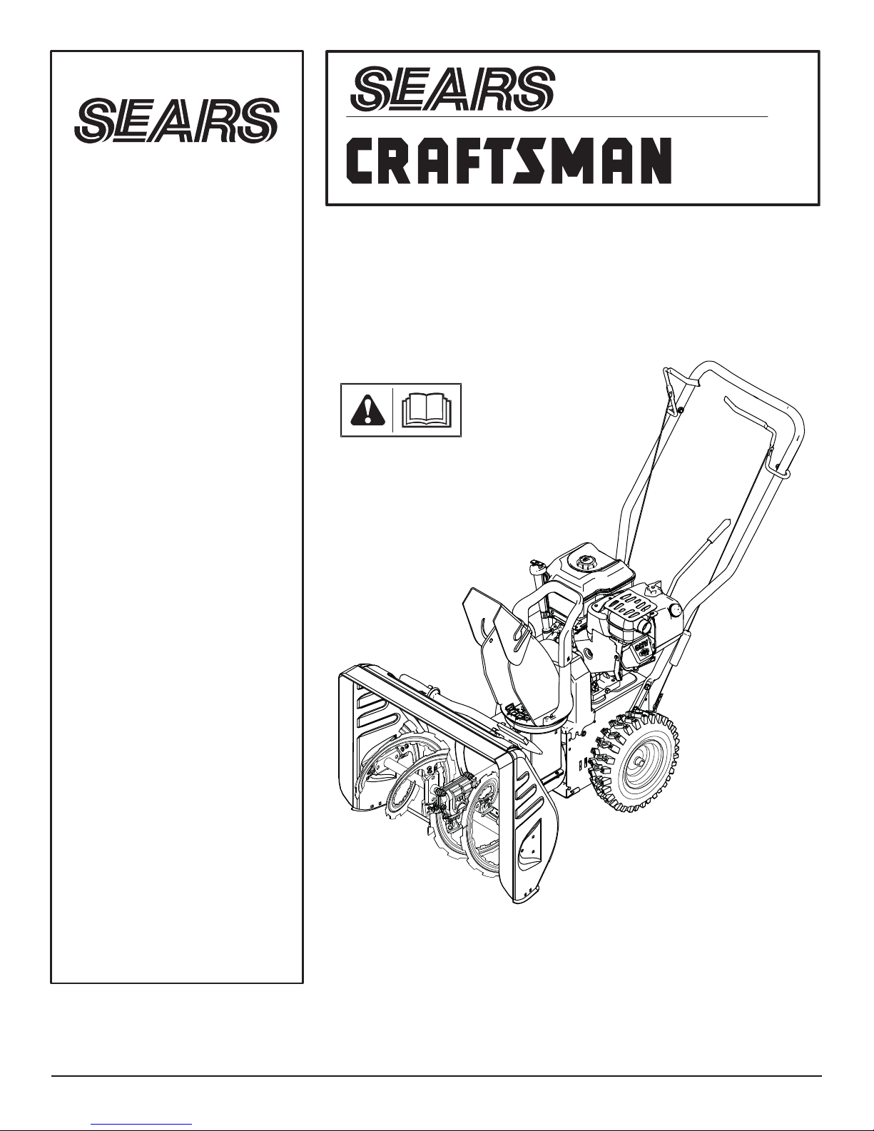
DUAL STAGE
Model
C950-52122-0
8.0 T.P. 24 inch
SNOWTHROWER
CAUTION:
You must read and
understand this owner’s
manual before operating
unit.
Serial No. ______________

2

3
TABLE OF CONTENTS
General Information
Thank you for purchasing this quality-built CRAFTSMAN snowthrower. We’re pleased that you’ve placed your confidence in the
CRAFTSMAN brand. When operated and maintained according to the instructions in this manual, your CRAFTSMAN product will
provide many years of dependable service.
This manual contains safety information to make you aware of the hazards and risks associated with snowthrowers and how to
avoid them. This snowthrower is designed and intended only for snow throwing and is not intended for any other purpose. It is important that you read and understand these instructions thoroughly before attempting to start or operate this equipment. Save
these instructions for future reference.
Contents ......................................................................................................................3
Operator Safety...........................................................................................................4
Features and Controls .............................................................................................10
Operation...................................................................................................................12
Safety System Test ...................................................................................................12
Maintenance..............................................................................................................17
Troubleshooting........................................................................................................21
Warranties.................................................................................................................23
Specifications ...........................................................................................................26
Product Reference Data
When contacting your authorized dealer for replacement parts, service, or information you MUST have these numbers.
Snowthrower
Model Number _________________________
Revision __________
Serial Number ______________________________
Engine
Model Number
_________________________
Revision __________
Serial Number ______________________________
Date Purchased ____________________
4
OPERATOR SAFETY
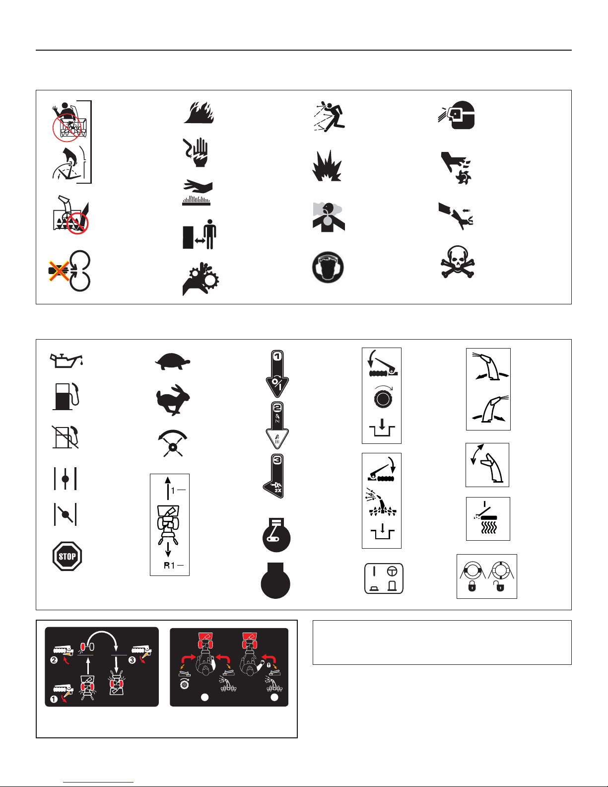
Hazard Symbols and Meanings
Rotating
Impeller
NOTE: Not all control symbols shown on this page will
appear on your snowthrower. See Features and Controls
section for the applicable symbols.
Rotating
Auger
Rotating
Parts
Fire
Shock
Hot
Surface
Safe
Distance
Rotating
Gears
Thrown
Objects
Explosion
Toxic
Fumes
Ear
Protection
Eye
Protection
Moving
Parts
Kickback
Hazardous
Chemical
Control Symbols on Equipment
Oil
Fuel
Fuel
Shutoff
Choke
Off
Choke
On
Stop
Slow
Fast
Auger
Clutch
Electric
Start
Engine
On-Off
ChokeRun
Traction
Control
Auger
Control
Discharge
Chute
Chute
Deflector
Heated
Hand
Grips
Forward
Neutral
Reverse
Engine
Primer
Engine
Run
Engine
Stop
Wheel
Lock
1
2
Free-Hand™ Control
Easy-Turn™
Traction Control
STOP
5
OPERATOR SAFETY
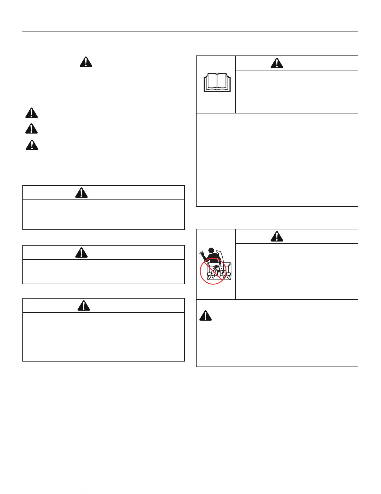
The safety alert symbol and signal word (DANGER,
WARNING, CAUTION, or NOTICE) is used to indicate the likelihood
and potential severity of personal injury and/or damage to the
product. In addition, a hazard symbol may be used to represent the
type of hazard.
Safety Alert Symbol and Signal Words
DANGER indicates a hazard which, if not avoided, will result
in death or serious injury.
WARNING indicates a hazard which, if not avoided, could
result in death or serious injury.
CAUTION indicates a hazard which, if not avoided, could
result in minor or moderate injury.
NOTICE indicates a situation that could result in damage
to the product.
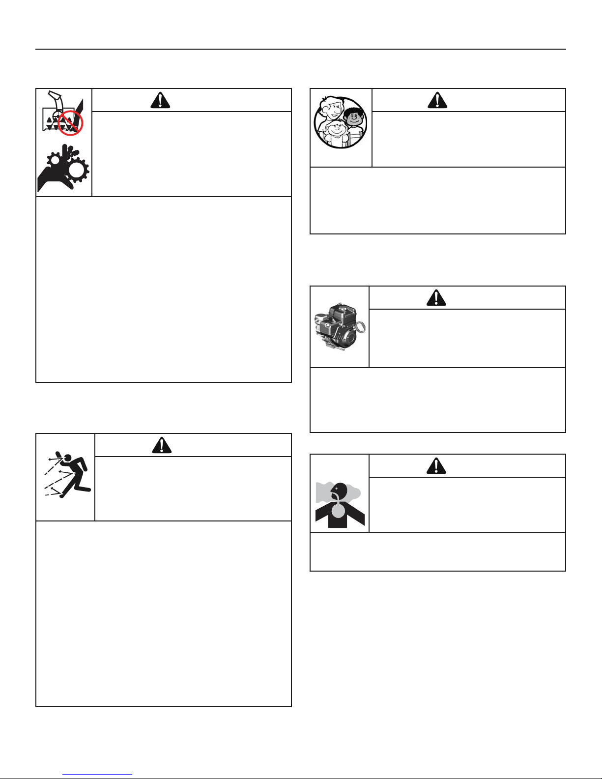
DANGER
• Hand contact with the rotating impeller inside the discharge
chute is the most common cause of injury associated with
snowthrowers.
• This snowthrower is capable of amputating hands and feet,
and throwing objects. Read and observe all the safety
instructions in this manual. Failure to do so will result in
death or serious injury.
WARNING
Certain components in this product and its related accessories
contain chemicals known to the state of California to cause
cancer, birth defects, or other reproductive harm. Wash hands
after handling.
WARNING
The engine exhaust from this product contains chemicals
known to the State of California to cause cancer, birth defects,
or other reproductive harm.
• Be thoroughly familiar with the controls and the proper use of the
snowthrower.
• Make sure you are properly trained before operating the
snowthrower.
• Know how to stop the unit and disengage the controls quickly.
• Never allow anyone to operate the snowthrower without proper
instruction.
• Always follow the instructions in the operator’s manual, if the
snowthrower will be stored for an extende d period.
• Maintain or replace safety and instruction labels as necessary.
• Never attempt to make major repairs on the snowthrower unless
you have been properly trained. Improper servicing of the
snowthrower can result in hazardous operation, equipment
damage, and voiding of the product warranty.
DANGER
Read, understand, and follow all the
instructions on the snowthrower and in the
operator’s manual before operating this unit.
Failure to observe the safet y instructions in
this manual will result in death or serious
injury.
Read the Manual
TO SAFELY CLEAR A CLOGGED DISCHARGE CHUTE
DANGER: Hand contact with the rotating impeller inside
the discharge chute is the most common cause of
injury associated with snowthrowers. Never use your
hands to clean out the discharge chute.
FOLLOW THESE INSTRUCTIONS:
1. Shut OFF the engine.
2. Wait 10 seconds to be sure the impeller blades have stopped
rotating.
3. Always use a clean-out tool, not your hands.
DANGER
Discharge chute contains rotating impeller to
throw snow. Never clear or unclog the
discharge chute with your hands. Fingers can
quickly become caught in the impeller. Always
use a clean-out tool.
Failure to observe these safety instructions
will result in traumatic amputation or severe
laceration.
Discharge Chute
6
OPERATOR SAFETY
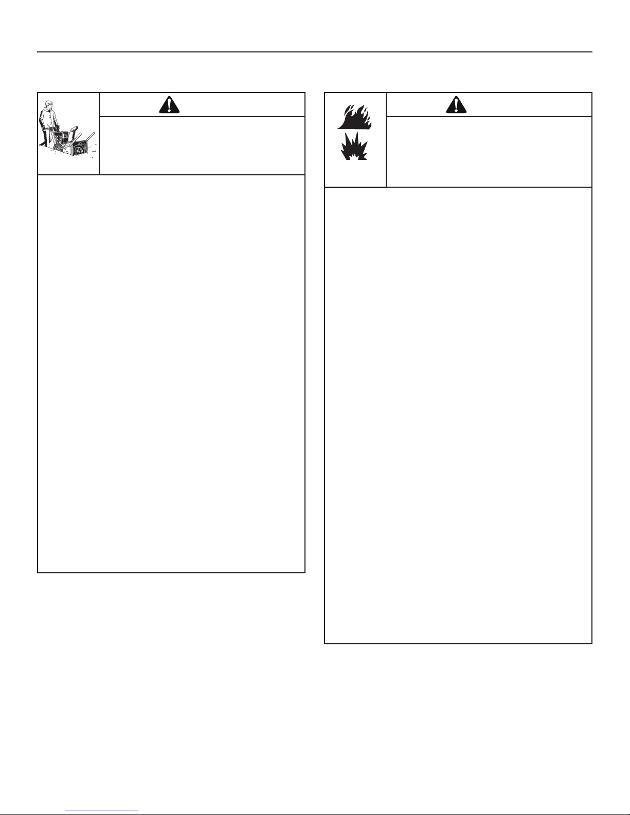
WHEN ADDING FUEL
• Turn off engine and let cool at least 2 minutes before removing
the fuel cap and adding fuel.
• Fill fuel tank outdoors or in a well ventilated area.
• Do not overfill the fuel tank. To allow for the expansion of gasoline,
do not fill above the bottom of the fuel tank neck.
• Keep fuel away from sparks, open flames, pilot lights, heat, and
other ignition sources.
• Check fuel lines, cap, and fittings frequently for cracks or leaks.
Replace if necessary.
• Use an approved fuel container.
• If fuel spills, wait until it evaporates before starting engine.
WHEN STARTING ENGINE
• Ensure that spark plug, muffler, fuel cap, and air cleaner (if
equipped) are in place and secured.
• Do not crank the engine with the spark plug removed.
• If fuel is spilled, do not attempt to start the engine, but move the
snowthrower away from the area of the spill, and avoid creating
any source of ignition, until the fuel vapors have dissipated.
• Do not over-prime the engine. Follow the engine starting
instructions in this manual.
• If the engine floods, set choke (if equipped) to OPEN/RUN
position, move throttle (if equipped) to FAST position and crank
until engine starts.
WHEN OPERATING EQUIPMENT
• Do not tip the snowthrower at an angle which causes the fuel to
spill.
• Do not choke the carburetor to stop the engine.
• Never run the engine with the air cleaner assembly (if equipped)
or the air filter (if equipped) removed.
WHEN CHANGING OIL
• If you drain the oil from the top oil fill tube, the fuel tank must be
empty or fuel can leak out and result in a fire or explosion.
WHEN TRANSPORTING EQUIPMENT
• Transport with fuel tank EMPTY, or with fuel shut-off valve OFF.
WHEN STORING GASOLINE OR EQUIPMENT WITH FUEL
IN TANK
• Store away from furnaces, stoves, water heaters, or other
appliances that have pilot light or other ignition source because
they can ignite fuel vapors.
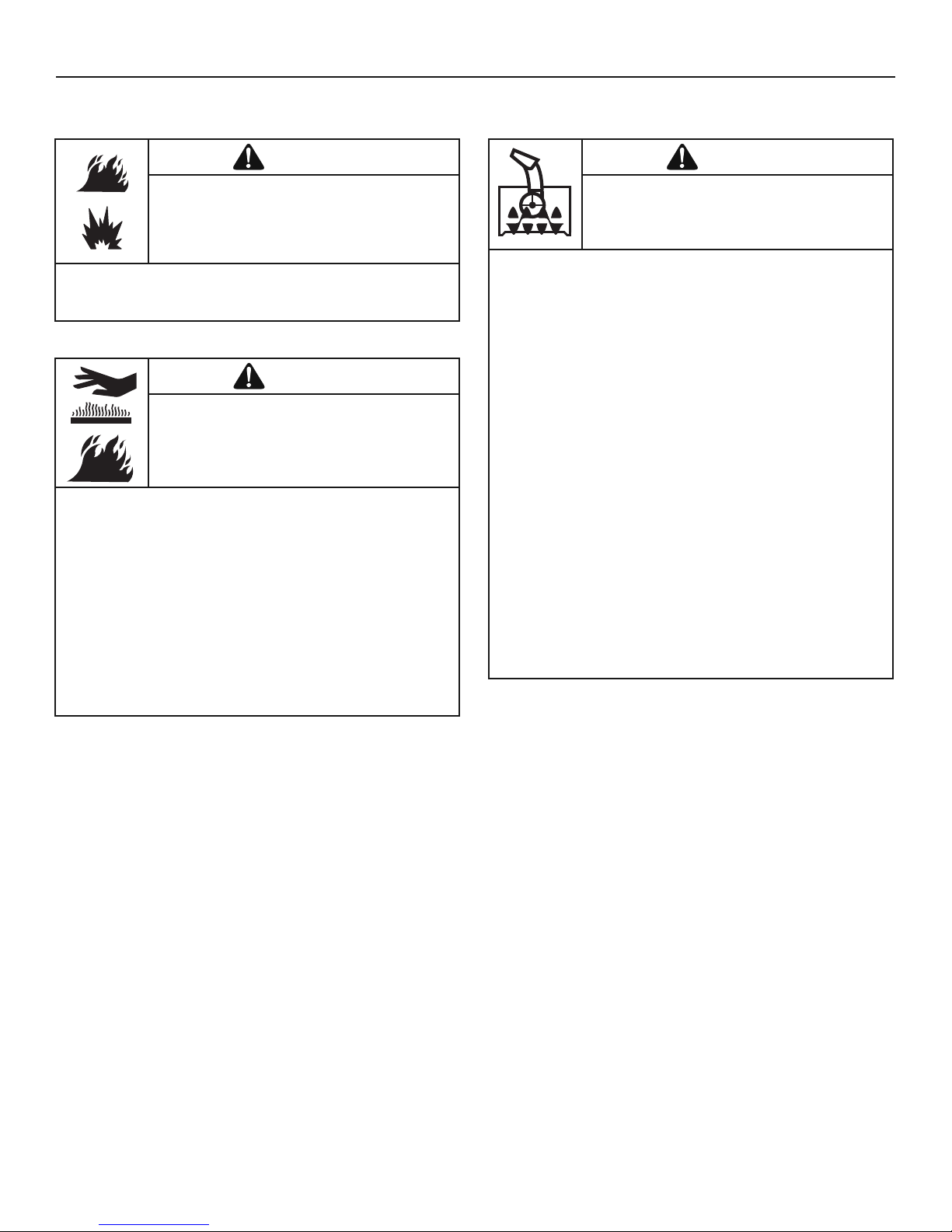
DANGER
Fuel and its vapors are extremely flammable
and explosive. Always handle fuel with extreme
care.
Failure to observe these safety instructions can
cause a fire or explosion which will result in
severe burns or death.
Fuel Handling
• Keep the area of operation clear of all persons, particularly small
children and pets.
• Thoroughly inspect the area where the snowthrower will be used
and remove all doormats, sleds, boards, wires, and other foreign
objects.
• Do not operate the snowthrower without wearing adequate winter
clothing.
• Wear footwear that will improve footing on slippery surfaces.
• Use caution to avoid slipping or falling especially when operating
the snowthrower in reverse.
• Never operate the snowthrower without good visibility or light.
Always be sure of your footing, and keep a firm hold on the
handles.
• Do not clear snow across the face of slopes. Use extreme caution
when changing direction on slopes. Do not attempt to clear steep
slopes.
• Do not overload the machine capacity by attempting to clear
snow too quickly.
• Never operate the snowthrower at high transport speeds on
slippery surfaces. Look behind the snowthrower and use care
when operating in reverse.
• Do not use the snowthrower on surfaces above ground level such
as roofs of residences, garages, porches, or other such structures
or buildings.
• Operators should evaluate their ability to operate the snowthrower
safely enough to protect themselves and others from injury.
• The snowthrower is intended to remove snow only. Do not use the
snowthrower for any other purpose.
• Do not carry passengers.
• After striking a foreign object, shut OFF the engine, disconnect
the cord on electric motors, thoroughly inspect the snowthrower
for any damage, and repair the damage before restarting and
operating the snowthrower.
• If the snowthrower vibrates abnormally, shut OFF the engine.
Vibration is generally a warning of trouble. See an authorized
dealer if necessary for repairs.
• For models equipped with electric starting motors, disconnect the
power cord after the engine starts.
DANGER
This snowthrower is only as safe as the
operator. If it is misused, or not properly
maintained, it can be dangerous. Remember
you are responsible for your safety and that of
those around you.
Operation and Equipment Safety
7
OPERATOR SAFETY
• Keep children out of the area during operation. Children are often
attracted to the equipment. Be mindful of all persons present.
• Be alert and turn unit off if children enter the area.
• Never allow children to operate the unit.
• Use extra care when approaching blind corners, shrubs, trees, or
other objects that may obscure vision. Children may be present.
DANGER
Tragic accidents can occur if the operator is
not alert to the presence of children. Children
are often attracted to the unit and the
operating activity. Never assume that children
will remain where you last saw them.
Children
• Start and run engine outdoors.
• Do not run the engine in an enclosed area, even if doors or
windows are open.
DANGER
Engines give off carbon monoxide, an odorless,
colorless, poison gas.
Breathing carbon monoxide can cause nausea,
fainting, or death.
Engine Safety
• Disengage all clutches and shift into neutral before starting the
engine.
• Let the engine adjust to outdoor temperatures before starting to
clear snow.
• Use a grounded three-wire plug-in for all snowthrowers equipped
with electric drive motors or electric starting motors.
DANGER
Safe operation of the snowthrower requires the
proper care and maintenance of the engine.
Failure to observe the safety instructions in this
manual will result in death or serious injury.
• Always wear safety glasses or eye shields during operation, and
while performing an adjustment or repair.
• Always be aware of the direction the snow is being thrown.
Nearby pedestrians, pets, or property may be harmed by objects
being thrown.
• Be aware of your environment while operating the snowthrower.
Don’t run over items such as gravel, doormats, newspapers, toys,
and rocks hidden under snow, as they can all be thrown from the
chute or jam in the auger.
• Use extreme caution when operating on or crossing gravel drives,
walks, or roads.
• Adjust the collector housing height to clear gravel or crushed rock
surface.
• Never operate the snowthrower near glass enclosures,
automobiles, window wells, drop-offs, and the like without proper
adjustment of the discharge chute angle.
• Familiarize yourself with the area in which you plan to operate the
snowthrower. Mark off boundaries of walkways and driveways.
DANGER
Objects can be picked up by auger and thrown
from chute. Never discharge snow toward
bystanders or allow anyone in front of the
snowthrower. Failure to observe these safety
instructions will result in death or serious
injury.
Thrown Objects
• Whenever cleaning, repairing, or inspecting the snowthrower,
make sure the engine is OFF, spark plug wire is disconnected,
and all moving parts have stopped.
• Do not put hands or feet near or under rotating parts. Keep clear
of the discharge opening at all times.
• Never operate the snowthrower without proper guards, and other
safety devices in place and working.
• Never leave the snowthrower unattended while engine is running.
Always disengage the auger and traction controls, stop engine,
and remove keys.
• Keep all loose clothing away from the front of the snowthrower
and auger. Scarves, mittens, dangling drawstrings, loose clothes,
and pants can quickly become caught in the rotating device and
amputation will occur. Tie up long hair and remove jewelry.
• Run the machine a few minutes after discharging snow to prevent
freeze-up of the collector/impeller.
• Disengage power to the collector/impeller when snowthrower is
transported or not in use.
DANGER
Keep hands, feet, and clothing away from
rotating parts. Rotating parts can contact or
entangle hands, feet, hair, clothing, or
accessories.
Failure to observe these safety instructions will
result in traumatic amputation or severe
laceration.
Moving Parts
8
OPERATOR SAFETY
• When performing any maintenance or repairs on the
snowthrower, shut OFF the engine, disconnect spark plug wire,
and keep the wire away from the plug to prevent someone from
accidently starting the engine.
• Check shear bolts and other hardware at frequent intervals for
proper tightness to be sure the snowthrower is in safe working
condition.
• Keep nuts and bolts tight and keep snowthrower in good
condition.
• Never tamper with safety devices. Check their proper operation
regularly and make necessary repairs if they are not functioning
properly.
• Components are subject to wear, damage, and deterioration.
Frequently check components and replace with recommended
parts, when necessary.
• Check control operation frequently. Adjust and service as
required.
• Use only factory authorized replacement parts, or equivalent,
when making repairs.
• Always comply with factory specifications on all settings and
adjustments.
• Only authorized service locations should be utilized for major
service and repair requirements.
• Use only attachments and accessories approved by the factory
(such as wheel weights, counterweights, or cabs).
• Never attempt to make any adjustments while the engine is
running (except when specifically recommended by the factory).
WARNING
This snowthrower must be properly maintained
to ensure safe operation and performance.
Failure to observe the safety instructions in this
manual could result in death or serious injury.
Maintenance and Storage
• If there is natural or LP gas leakage in area, do not start engine.
• Do not use pressurized starting fluids because vapors are
flammable.
WARNING
Starting engine creates sparking.
Sparking can ignite nearby flammable gases.
Explosion and fire could result.
• Never touch a hot engine or muffler. Allow muffler, engine
cylinder, and fins to cool before touching.
• Remove debris from muffler area and cylinder area.
• Install and maintain in working order a spark arrester before using
equipment on forest-covered, grass-covered, or brush-covered
unimproved land.
• It is a violation of California Public Resource Code, Section 4442,
to use or operate the engine on any forest-covered, brushcovered, or grass-covered land unless the exhaust system is
equipped with a spark arrester, as defined in Section 4442,
maintained in effective working order. Other states or federal
jurisdictions may have similar laws. Contact the original
equipment manufacturer, retailer, or dealer to obtain a spark
arrester designed for the exhaust system installed on this engine.
WARNING
Running the engine produces heat. Engine
parts, especially muffler, become extremely hot.
Failure to observe these safety instructions
could result in severe thermal burns on contact.
Engine Safety (Continued)
9
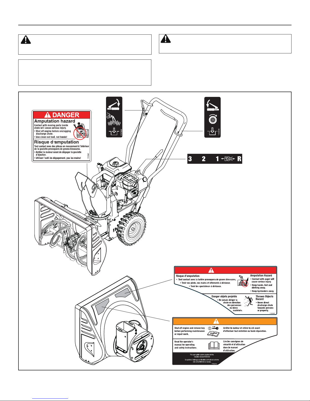
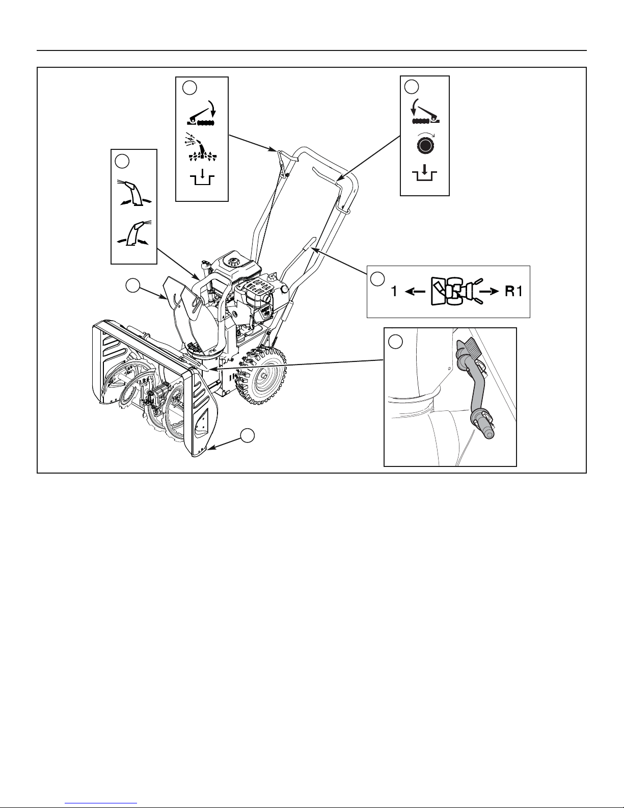
Figure 1
Look for this symbol to indicate important safety
pre cautions. This symbol indicates: “Attention! Become
Alert! Your Safety Is At Risk.”
WARNING: If any safety decals become worn or
damaged and cannot be read, order replacement decals
from your local dealer.
OPERATOR SAFETY
Before operating your snowthrower, read the safety decals
as shown on your snowthrower. The cautions and warnings
are for your safety. To avoid a personal injury or damage to
your snowthrower, understand and follow all the safety decals.
Part No. 1737865
Chute Danger Decal
Part No. 1752826
Shift Decal
Part No. 1752422
Auger Danger Decal
Product ID Number &
Serial Number Decal
(Rear of Motor Box)
Part No. 1752919
Engine Decal
Part No. 1737869
Auger Control Decal
Part No. 1737870
Traction Control Decal
WARNING
DANGER
AVERTISSEMENT
10
Figure 2
SNOWTHROWER CONTROLS
A. Chute Rotation Handle — Used to change direction of the snow
discharge.
B. Auger Control Lever — Used to engage and disengage the
auger and impeller. To engage push down, to disengage release.
C. Traction Control Lever — Used to propel snowthrower for-
ward or reverse. Push down to engage, release to disengage.
D. Speed Select Lever — Allows the operator to use one of four (3)
forward and (1) reverse speeds (see Figure 2). To shift, move speed
select lever to desired position.
NOTICE: Do not move speed select lever while Traction
Control Lever is engaged. This may result in severe damage to drive system.
E. Clean-Out Tool — Used to remove snow and debris from the dis-
charge chute and the auger housing.
F. Skid Shoe — Used to adjust ground clearance of auger housing.
G. Chute Deflector Wing Nut — Used to control the angle of the
chute deflector (up or down).
FEATURES AND CONTROLS
G
F
A
B
C
E
D

FEATURES AND CONTROLS
11
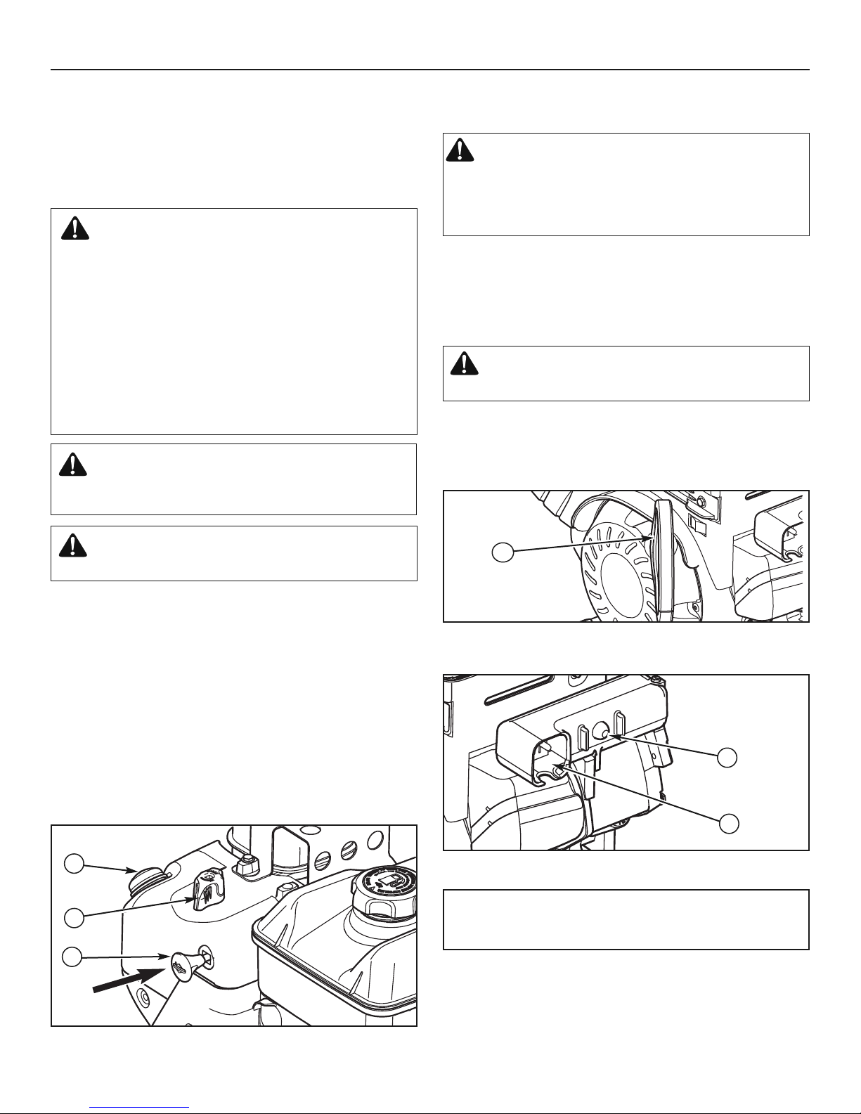
ENGINE CONTROLS
A. Choke Control Knob — Used to start a cold engine (see Figure 3).
B . Oil Fill Cap (Extended Dipstick)
C. Fuel Tank and Cap — Fill the fuel tank to approximately 1-1/2 in.
(38 mm) below the top of the neck to allow for fuel expansion.
D. Fuel Shut-Off Valve (if equipped) — Used to turn the fuel supply
off for out-of-season storage.
Figure 3
E. Starter Cord Handle — Used to start the engine manually.
F. Safety Key — Must be inserted to start engine. Pull out to stop. Do
not turn safety key.
G. Primer Button — Used to inject fuel directly into the carburetor
manifold to ensure fast starts in cool weather.
H. Electric Start Button — Used to start the engine using the electric
starter.
G
B
A
E
C
F
D
H
STOP
12
BEFORE OPERATING SNOWTHROWER
■ Check the fasteners. Make sure all fasteners are tight.
■ Read this OPERATOR’S MANUAL and OPERATOR SAFETY before
operating your snowthrower. Compare the illustrations with your
SNOWTHROWER to familiarize yourself with the location of various controls and adjustments. Save this manual for future reference.
NOTE: This snowthrower was shipped WITH OIL in the
engine. See “Check The Oil (Before Starting Engine)”
instructions in the OPERATION section of this manual before
starting engine.
OPERATION
OPERATE THE SNOWTHROWER
The most effective use of the snowthrower will be established by experience, taking into consideration the terrain, wind conditions, and building
location which will determine the direction of the discharge chute.
NOTICE: Do not throw snow toward a building as hidden objects
could be thrown with sufficient force to cause damage.
1. Start the engine. See “Start The Engine” in this section.
2. Rotate the handle (A, Figure 2) to set the direction (left or right) of the
discharge chute.
3. Adjust the snow chute deflector. Loosen the wing nut (G) on the side
of the snow chute and raise the chute deflector for more distance, or
lower it for less distance. Then tighten the wing nut.
WARNING: The operation of any snowthrower can result in foreign objects being thrown into the eyes, which can result in
severe eye damage. Always wear safety glasses or eye shields before beginning snowthrower operation. We recommend
standard safety glasses or Wide Vision Safety Mask over spectacles.
CAUTION: Before operating, make sure the area in front
of the snowthrower is clear of bystanders or obstacles.
NOTE: Always release the traction control lever before moving
the speed select lever.
4. Use the speed select lever (D, Figure 2) to select the forward drive
speed. Set the speed select lever to one of the following positions as
determined by snow conditions:
1 Wet, Heavy, Slushy, Extra Deep
2 Moderate
3 Very Light, Transport
NOTE: When clearing wet, heavy, snow, it is recommended that
the ground speed of the unit be reduced, maintain full throttle,
and do not attempt to clear the full width of the unit.
5. Engage the auger drive clutch lever (A, Figure 4).
DOWN Engage Position
UP Disengage Position
6. Engage the traction drive clutch lever (B). As the snowthrower starts
to move, maintain a firm hold on the handles and guide the
snowthrower along the cutting path. Do not attempt to push the
snowthrower.
7. To stop forward motion, release the traction drive clutch lever (B).
Figure 4
B
A
SAFETY SYSTEM TEST
WARNING
Amputation Hazard
This snowthrower is equipped with several mechanical safety
systems designed to keep the operator safe while using the unit.
Check the operation of these systems regularly using the safety
system tests listed. If the unit fails to operate as described, DO NOT
operate it. See your authorized dealer for service immediately.
Test 1 – Auger/Impeller Control
With the engine running:
• Press down on the auger control lever. (The auger/impeller should rotate.)
• Release the auger control lever. (The auger/impeller should stop within 5
seconds.)
Test 2 – Traction Drive Control
With the engine running and speed control in 1st gear:
• Press down on the traction control lever. (The unit should move forward.)
• Release the traction control lever. (The unit should stop.)

13
OPERATION
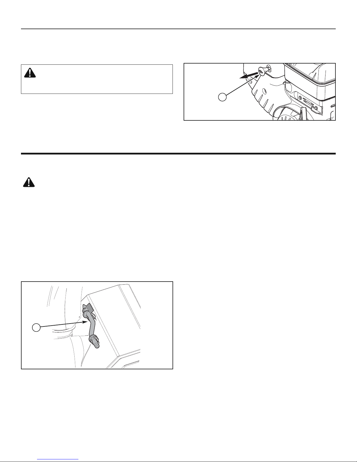
STOP THE SNOWTHROWER
1. Release the traction drive clutch lever (B, Figure 4).
2. Remove the safety key (A Figure 11). Keep the safety key out of the
reach of children.
WARNING: Read Operator’s Manual before operating
machine. This machine can be dangerous if used
carelessly.
• Never operate the snowthrower without all guards,covers,
shields in place.
• Never direct discharge towards windows or allow
bystanders near machine while engine is running.
• Stop the engine whenever leaving the operating
position.
• Disconnect spark plug before unclogging the impeller
housing or the discharge chute and before making
repairs or adjustments.
• When leaving the machine, remove the safety key. To
reduce the risk of fire, keep the machine clean and free
from spilled gas, oil, and debris.
8. To stop the auger, release the auger drive clutch lever (A).
9. To move the snowthrower backwards, move the speed select lever
(D, Figure 2) into reverse (R), and engage the traction drive clutch lever
(B, Figure 4).
WARNING: Never run engine indoors or in an enclosed,
poor ventilated area. Engine exhaust contains CARBON
MONOXIDE, an ODORLESS and DEADLY GAS.
• Keep hands, feet, hair, and loose clothing away from
any moving parts on engine and snowthrower.
• Temperature of muffler and nearby areas can exceed
150°F (66°C). Avoid these areas.
• DO NOT allow children or young teenagers to operate or
be near snowthrower while it is operating.
CHECK THE OIL (BEFORE STARTING
ENGINE)
NOTE: The engine was shipped from the factory filled with oil.
Check the level of the oil. Add oil as needed.
1. Make sure the unit is level. Use a high quality detergent oil classified
“For Service SF, SH, SJ, SL, or higher”.
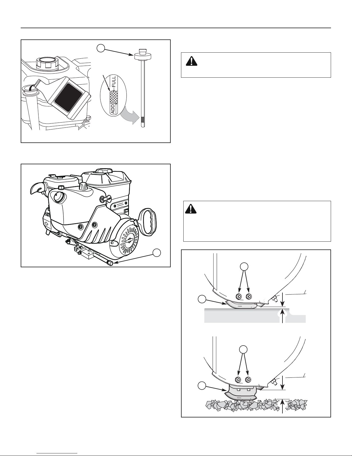
2. Remove the oil fill cap/dipstick (A, Figure 5) and wipe with a clean cloth.
3. Insert the oil fill cap/dipstick and turn clockwise to tighten.
4. Remove the oil fill cap/dipstick and check the oil.
NOTE: Do not check the level of the oil while the engine runs.
5. If necessary, add oil until the oil reaches the FULL mark on the oil fill
cap/dipstick. Do not add too much oil.
6. Tighten the oil fill cap/dipstick securely each time you check the oil
level.
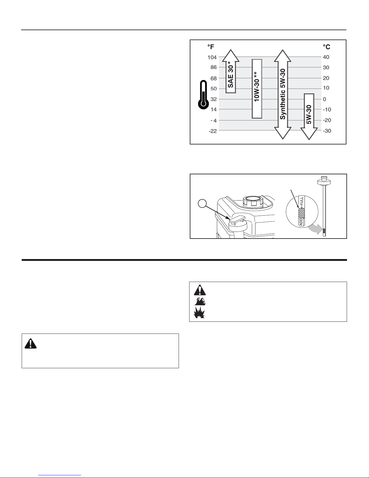
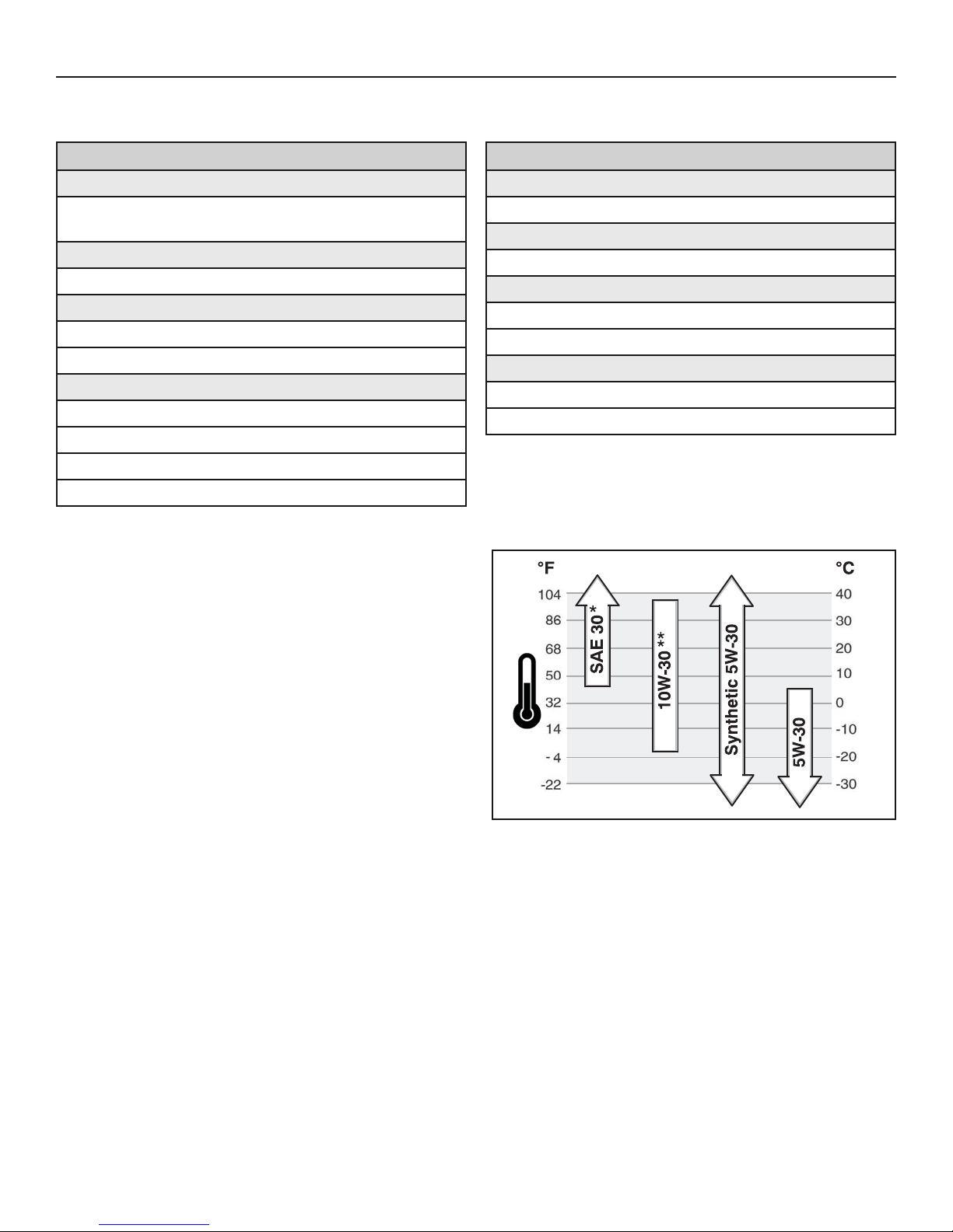
NOTE: For extreme cold operating conditions of 0°F (-18°C) and
below, use a synthetic 5W30 motor oil for easier starting.
NOTE: S.A.E. 5W30 motor oil may be used to make starting
easier in areas where the temperature is 20°F (-7°C) to 0°F
(-18°C). Synthetic 5W30 is acceptable for all temperatures.
DO NOT mix oil with gasoline. See Chart for oil recommendations.
FULL
Figure 5
A
OPERATION
* Below 40°F (4°C) the use of SAE 30 will result in hard starting.
** Above 80°F (27°C) the use of 10W-30 may cause increased oil consumption. Check
oil level more frequently.
14
FUEL RECOMMENDATIONS
Fuel must meet these requirements:
• Clean, fresh, unleaded gasoline.
• A minimum of 87 octane/87 AKI (91 RON). High altitude use,
see below.
• Gasoline with up to 10% ethanol (gasohol) or up to
15% MTBE (methyl tertiary butyl ether) is acceptable.
CAUTION: Do not use unapproved gasolines, such as
E85. Do not mix oil in gasoline or modify the engine to
run on alternate fuels. This will damage the engine com
ponents and void the engine warranty.
To protect the fuel system from gum formation, mix a fuel stabilizer
into the fuel. All fuel is not the same. If starting or performance
problems occur, change fuel providers or change brands. This engine is certified to operate on gasoline. The emissions control system for this engine is EM (Engine Modifications).
ADDING FUEL
WARNING
Fuel and its vapors are extremely flammable
and explosive.
Fire or explosion can cause severe burns or
death.
When Adding Fuel
• Turn engine off and let engine cool at least 2 minutes
before removing the fuel cap.
• Fill fuel tank outdoors or in well-ventilated area.
• Do not overfill fuel tank. To allow for expansion of the fuel,
do not fill above the bottom of the fuel tank neck.
• Keep fuel away from sparks, open flames, pilot lights,
heat, and other ignition sources.
• Check fuel lines, tank, cap, and fittings frequently for
cracks or leaks. Replace if necessary.
• If fuel spills, wait until it evaporates before starting engine.
15
OPERATION
Start the engine as follows:
1. Check the oil level. See the “Check the Oil” section.
2. Make sure equipment drive controls are disengaged.
3. Insert the safety key (A, Figure 6) into the safety key slot and push
fully in to the RUN position.
4. Turn the choke control knob (B) to the CHOKE position.
NOTE: Do not use the choke to start a warm engine.
5. Push the primer button (C) two times.
NOTE: Do not use the primer to start a warm engine.
NOTE: Ensure that electric extension cord is removed from the
power receptacle.
START THE ENGINE
Be sure that engine oil is at FULL mark on the oil fill cap/dipstick. The snowthrower
engine is equipped with an A.C. electric starter and recoil starter. Before starting the
engine, be certain that you have read the following information.
If engine floods, set the choke to the OPEN/RUN position and crank until the engine starts.
WARNING: The electric starter is equipped with a
three−wire power cord and plug designed to operate on AC
house hold current. The power cord must be properly
grounded at all times to avoid the possibility of electric
shock which can cause injury to the operator. Follow all
instructions carefully as set forth:
Make sure your house has a three−wire grounded system.
If you are not sure, ask a licensed electrician. If your house does
not have a three−wire grounded system, do not use this electric
starter under any condition.
If your house has a three−wire grounded system but a three-hole
receptacle is not available to connect the electric starter, have a
three−hole receptacle installed by a licensed electrician.
WARNING: To connect power cord, always connect the
power cord first to the switch box located on the
engine and then plug the other end into a three−hole
grounded receptacle.
WARNING: To disconnect the power cord, always
unplug the end connected to the three−hole grounded
receptacle first.
6. Rewind Start: Firmly hold the starter cord handle (A, Figure 7). Pull the
starter cord handle slowly until resistance is felt, then pull rapidly.
WARNING: Rapid retraction of the starter cord (kickback)
will pull your hand and arm toward the engine faster
than you can let go. Broken bones, fractures, bruises,
or sprains could result. When starting engine, pull the
starter cord slowly until resistance is felt and then pull
rapidly to avoid kickback.
NOTE: If the engine does not start after three attempts, see
authorized dealer.
7. Electric Start: First connect the extension cord to the power cord
receptacle and then into a wall receptacle. If additional extension cord is
required, make sure it is three-wire.
WARNING: If the extension cord is damaged, it must
be replaced by the manufacturer (or its service agent)
or a similarly qualified person to avoid a hazard.
A
B
C
Figure 6
Figure 8
IMPORTANT: To extend the life of the starter, use short
starting cycles (five seconds maximum). Wait one minute
between starting cycles.
NOTE: If the engine does not start after three attempts, see
authorized dealer.
Figure 7
A
B
8. Electric Start: Depress the starter push button (A, Figure 8). After you
start the engine, first disconnect the extension cord from the wall receptacle
and then from the power cord receptacle (B).
A
16
OPERATION
CLEAR A CLOGGED DISCHARGE CHUTE
WARNING: Hand contact with the rotating impeller
inside the discharge chute is the most common cause of
injury associated with snowthrowers. Never clear or
unclog discharge chute with your hands, or while engine
is running. Fingers can quickly become caught and
traumatic amputation or severe laceration can result.
OPERATING TIPS
1. Most efficient snowthrowing is accomplished when snow is removed
immediately after it falls.
2. For complete snow removal, slightly overlap each swath previously taken.
3. Snow should be discharged downwind whenever possible.
4. For normal usage, set the skids 1/8 inch (3 mm) below the scraper
bar. For extremely hard-packed snow surfaces, the skids may be adjusted upward to ensure cleaning efficiency.
5. On gravel or crushed rock surfaces, the skids should be set at 1-1/4
inch (32 mm) below the scraper bar (see “Adjust Skid Height” in the
MAINTENANCE section of this manual). Rocks and gravel must not
be picked up and thrown by the machine.
6. After the snowthrowing job has been completed, allow the engine to
idle for a few minutes, to melt snow and ice accumulated on the
engine.
7. Clean the snowthrower thoroughly after each use.
8. Remove ice and snow accumulation and all debris from the entire
snowthrower, and flush with water (if possible) to remove all salt or
other chemicals. Wipe snowthrower dry.
9. Before starting snowthrower, always inspect augers and impeller for
ice accumulation and/or debris, which could result in snowthrower
damage.
10. Check oil level before every start. Make sure the oil is at the FULL
mark on the oil fill cap/dipstick.
Figure 10
A
• SHUT OFF THE ENGINE!
• Wait 10 seconds to be sure that the impeller blades have
stopped rotating.
• Always use a clean-out tool, not your hands.
A clean-out tool (A, Figure 10) is attached to either the handle or the top of the
auger housing. Use the clean-out tool to remove snow from the auger housing.
STOP THE ENGINE
Before stopping the engine, allow it to run for a few minutes to help dry off
any moisture on the engine.
WARNING: Gasoline and vapors are extremely
flammable and explosive. Fire or explosion can
cause severe burns or death. DO NOT choke the
carburetor to stop the engine.
1. Remove the safety key (A). Keep the safety key out of the reach of
children.
Figure 9
NOTE: Do not lose the safety key. Keep the safety key in a safe
place. The engine will not start without the safety/ignition key.
A
17
EMISSIONS CONTROL STATEMENT
Maintenance, replacement, or repair of the emissions control devices and
systems may be performed by any non-road engine repair establishment or
individual. However, to obtain “no charge” emissions control service, the
work must be performed by a factory authorized dealer. See the Emissions
Warranty.
ENGINE MAINTENANCE
Check Crankcase Oil Level - Before starting engine and after each 8
hours of continuous use. Add the recommended motor oil as required.
NOTE: Over filling the engine can affect performance. Tighten
the oil fill cap securely to prevent leakage.
Change Oil - Every 50 hours of operation or at least once a year, even if
the snowthrower is not used for fifty hours. Use a clean, high quality
detergent oil. Fill the crankcase to FULL line on dipstick (A, Figure 11). Be
sure original container is marked: A.P.I. service “SF” or higher. Do not use
SAE10W40 oil (as it may not provide proper lubrication). See Chart for
oil recommendations.
Drain Oil – Position snowthrower so that the oil drain plug (A, Figure 12)
is lowest point on engine. When the engine is warm, remove oil drain plug
and oil fill cap and drain oil into a suitable container.
Replace oil drain plug and tighten securely. Refill crankcase with the recommended motor oil.
* Below 40°F (4°C) the use of SAE 30 will result in hard starting.
** Above 80°F (27°C) the use of 10W-30 may cause increased oil consumption. Check
oil level more frequently.
MAINTENANCE
MAINTENANCE CHART
SNOWTHROWER
After Each Use
Remove the snow and slush off snowthrower to prevent
freezing of controls
Every 8 Hours or Daily
Perform snowthrower safety tests
Every 25 Hours or Annually *
Check tire pressure
Check snowthrower for loose hardware
See Dealer Annually to
Lubricate control levers and linkages
Lubricate deflector hinge
Lubricate deflector motor (if equipped)
Lubricate chute rotation gear (if equipped)
ENGINE
First 5 Hours
Change engine oil
Every 8 Hours or Daily
Check engine oil level
Every 50 Hours or Annually *
Change engine oil
Check muffler and muffler guard.
See Dealer Annually to
Replace spark plug
Check valve clearance
* Not required unless there are problems with engine
performance.
18
Figure 11
Full
Figure 12
A
A
MAINTENANCE
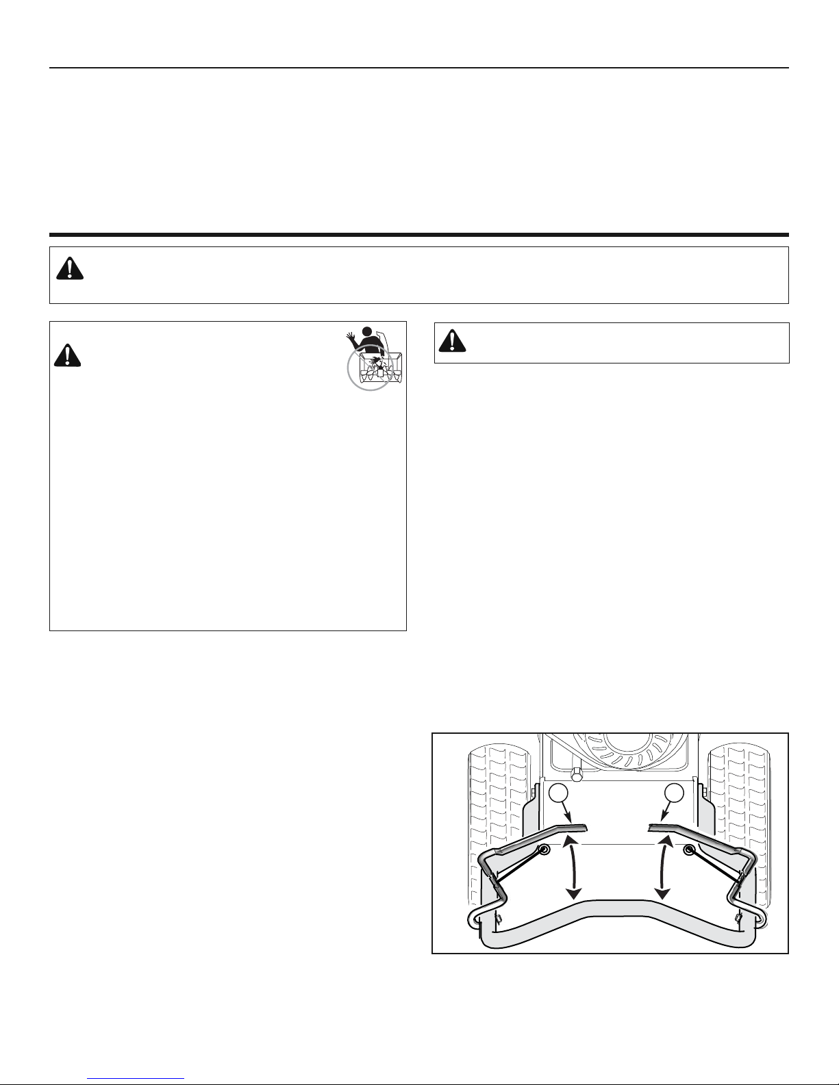
This snowthrower is equipped with two height adjust skids, secured to the
inside of the auger housing. These elevate the front of the snowthrower.
When removing snow from a hard surface area such as a paved driveway
or walk, adjust the skids up to bring the front of the snowthrower down.
When removing snow from rock or uneven construction, raise the front of
the snowthrower by moving the skids down. This will help to prevent rocks
and other debris from being picked up and thrown by the augers.
To adjust skids, proceed as follows:
1. Place a block (equal to height from ground desired) under scraper bar
near but not under skid.
2. Loosen skid mounting nuts (A, Figure 13) and push the skid down
(B) until it touches the ground. Retighten mounting nuts.
3. Set skid on other side at same height.
NOTE: Make sure that snowthrower is set at same height on
both sides.
Figure 13
WARNING: Be certain to maintain proper ground
clearance for your particular area to be cleared.
Objects such as gravel, rocks, or other debris, if struck
by the impeller, may be thrown with sufficient force to
cause personal injury, property damage, or damage to
the snowthrower.
ADJUST SKID HEIGHT
WARNING: Always turn unit off, remove ignition key,
and disconnect the spark plug wire before making
any repairs or adjustments.
A
A
B
B
1/8” - 3/16″
(3 mm - 5 mm)
1″
(2,5 cm)
19
MAINTENANCE
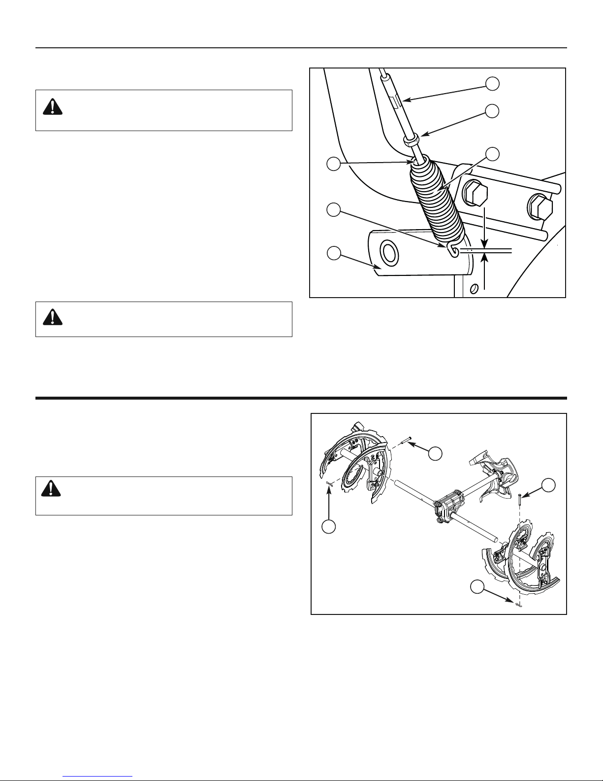
1. With the auger control lever released, the hook (A, Figure 14)
should barely touch the lever (B) without raising it. There can
be a maximum of 1/32 in. (0.8 mm) clearance.
2. To adjust, loosen the nut (C) by holding the adjusting flats (D)
and turning the nut. Then, turn the adjusting flats and hold the
adjustment screw (E). The adjustment screw is a phillips screw
and the head can be held or turned by inserting a screwdriver
through the spring (F).
3. Hold the adjusting flats and tighten the nut.
4. Start the engine and check the auger. The auger must not be
engaged unless the auger control lever is depressed.
5. With the engine running, fully depress the auger drive control
lever. The auger should engage and run normally.
1/32"
(0.8mm)
A
B
C
D
E
F
WARNING: Do not over-tighten, as this may lift the
lever and cause the auger drive to be engaged
without depressing the auger drive control.
Figure 14
AUGER CONTROL CABLE ADJUSTMENT
WARNING: The auger must stop within 5 seconds. If it
does not, see an authorized dealer.
8. If the drive linkage is properly adjusted, the tension of the
auger drive belt may require an adjustment. See an authorized
dealer.
AUGER SHEAR PIN REPLACEMENT
The augers are secured to the auger shaft with special shear pins
that are designed to break if an object becomes lodged in the
auger housing. Use of a harder grade shear pin will reduce the
protection provided by the shear pin.
WARNING: Do not go near the discharge chute or
auger when the engine is running. Do not run the
engine if any cover or guard is removed.
Under most circumstances, if the auger strikes an object which
could cause damage to the unit, the shear pin will break. This protects the gear box and other parts from damage. The shear pins
(A, Figure 15) are located on the auger shaft. Replace a broken
shear pin as follows.
1. Stop the engine, disengage all controls, disconnect the spark
plug lead wire, and make sure all moving parts have stopped.
2. Tap out the broken shear pin with a pin punch.
3. Align the hole in the auger with the hole in the auger shaft. Install a new shear pin (A, Figure 15) and cotter pin (B). Bend
the ends of the cotter pin down.
IMPORTANT: Do not replace shear pins with anything
other than the correct grade replacement shear pin. Use
of bolts, screws, or harder grade shear pins can result in
equipment damage.
Figure 15
B
B
A
A
6. Release the auger control lever.
7. If the auger does not operate properly, stop the engine and
recheck the auger control cable adjustment.
OFF-SEASON STORAGE
If the unit will be stored for thirty (30) days or more at the end of the
season, the following steps are recommended to prepare it for
storage. Always refer to the operator's manual for important details
if the unit is to be stored for an extended period.
NOTE: Fuel must be removed or treated to prevent gum
deposits from forming in the tank, filter, hose, and carburetor
during storage.
DANGER: Fire and Explosion Hazard
Gasoline is highly flammable and its vapors are explosive.
Fumes may travel to a distant ignition source and an explosion
and/or fire may result.
Handle gasoline carefully. Never store the unit, with fuel in the
tank, indoors or in a poorly ventilated enclosure where fuel
fumes could reach an open flame, spark, pilot light, such as a
furnace, water heater, or clothes dryer.
• Thoroughly clean the unit.
• Lubricate all lubrication points (see authorized dealer).
• Make sure all nuts, bolts, and screws are securely fastened.
Inspect all visible moving parts for damage, breakage, and wear.
Replace if necessary.
• Touch up all rusted or chipped paint surfaces; sand lightly before
painting.
• Cover the bare metal parts of the snowthrower housing auger,
and the impeller with rust preventative.
• If possible, store your unit indoors and cover it to give protection
from dust and dirt.
• If the machine must be stored outdoors, cover with a heavy
tarpaulin.
To Return to Service:
• Fill the fuel tank with a fresh fuel.
• Make sure all fasteners are tight.
• Make sure all guards, shields, and covers are in place.
20
MAINTENANCE
Figure 16
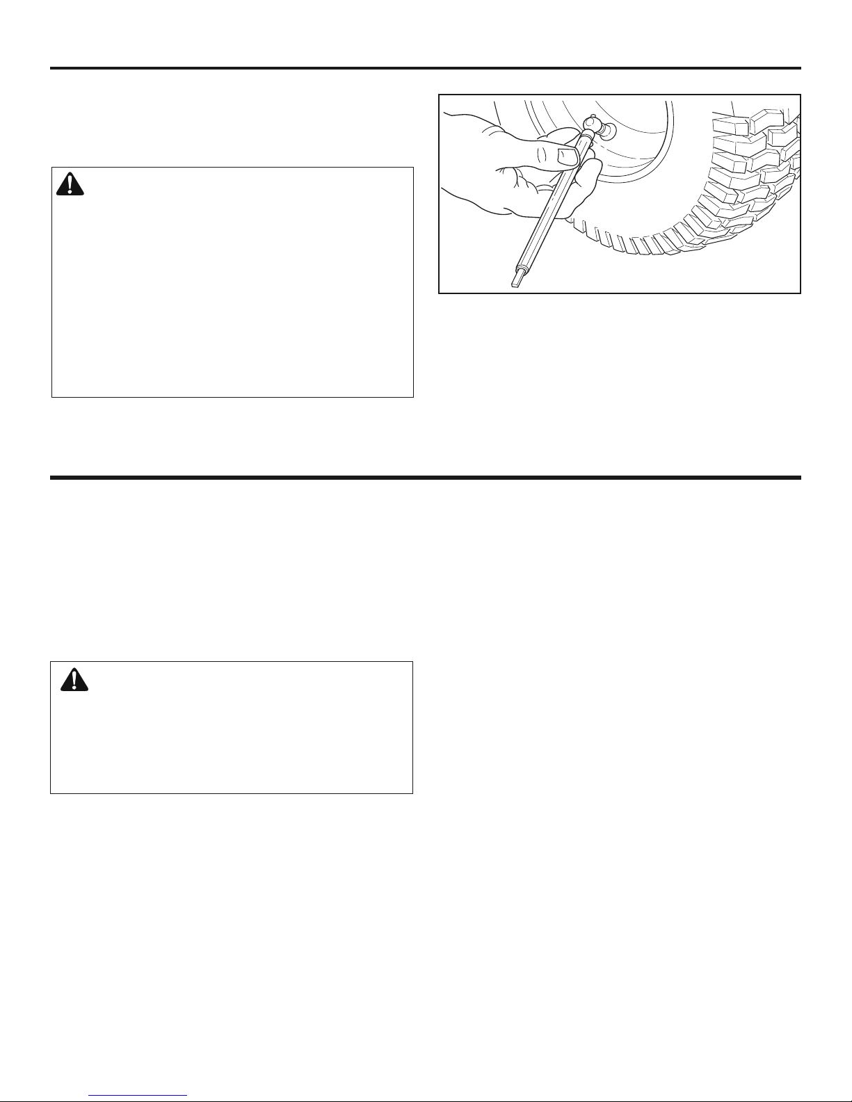
CHECK THE TIRES
Check tires for damage. Check the air pressure in the tires with an
accurate gauge (see Figure 16).
CAUTION: Avoid Injury! Explosive separation of tire
and rim parts is possible when they are serviced
incorrectly.
• Do not attempt to mount a tire without the proper
equipment and experience to perform the job.
• Do not inflate the tires above the maximum pressure.
• Do not weld or heat a wheel and tire assembly. Heat can
cause an increase in air pressure resulting in an
explosion. Welding can structurally weaken or deform the
wheel.
• Do not stand in front or over the tire assembly when
inflating. Use appropriate tool that allows you to stand to
one side.
NOTICE: Check side of tire for maximum tire pressure. DO
NOT exceed maximum.

21
TROUBLESHOOTING
PROBLEM LOOK FOR REMEDY
Auger does not stop
within 5 seconds after
right control lever is
released.
Free-Hand™ control is
ACTIVE.
Release both auger control and traction/Free-Hand™ control
levers to stop auger.
Free-Hand™ control is
not working correctly (fails
Safety Test 3).
See authorized dealer.
Auger control cable out of
adjustment (fails Safety
Test 1).
Adjust auger control cable. Refer to “Auger Control Cable
Adjustment” in the Maintenance section of this manual. Make sure
auger control passes Safety Test 1.
Auger belt guide out of
adjustment.
See authorized dealer.
Discharge chute or
deflector does not work
(electric).
Electrical failure. See authorized dealer.
Discharge chute or
deflector does not work
(remote-manual).
Discharge chute or
deflector out of
adjustment or needs
lubrication.
See authorized dealer.
Engine fails to start. Key is off. Push key in to the ON position.
Failure to prime a cold
engine.
Press primer button twice and start.
Fuel shut-off valve is
CLOSED position (if
equipped).
Turn valve to OPEN position.
Out of fuel. Fill fuel tank.
Choke OFF - cold engine. Turn choke ON, set throttle to FAST.
Engine flooded. Turn choke to OFF; try starting.
No spark. See authorized dealer.
Water in fuel, or old fuel. Drain tank. (Dispose of fuel at an authorized hazardous waste
facility.) Fill with fresh fuel.
Cord not plugged in or
malfunctions (Electric
Start models).
Plug in cord or replace defective cord.
Engine starts hard or
runs poorly.
Fuel mixture too rich. Move choke to OFF position.
Spark plug faulty, fouled,
or gapped incorrectly.
See authorized dealer.
Fuel cap vent is blocked. Clear vent.
Excessive vibration. Loose parts or damaged
impeller/auger.
Stop engine immediately. See authorized dealer.

22
TROUBLESHOOTING
PROBLEM LOOK FOR REMEDY
Snowthrower forward
and reverse motion
does not stop when
traction control lever is
released.
Traction control out of
adjustment (fails Safety
Test 2).
See authorized dealer.
Snowthrower veers to
one side.
Tire pressure not equal. Check tire pressure.
One wheel is set in freewheeling mode. (Traction
lock pin is in the OUTER
hole.) Models with wheel
pins or locks.
Make sure the left traction lock pin is in the INNER holes (to
engage the traction drive).
Scraper bar does not
clean hard surface.
Skid shoes improperly
adjusted.
Adjust skid shoes as needed.
Snowthrower fails to
move at slow speeds.
Traction control out of
adjustment.
Move speed select lever one speed faster. If that doesn’t work, see
authorized dealer.
Snowthrower fails to
move forward or
reverse at any speed.
Drive belt loose or
damaged.
See authorized dealer.
Traction control out of
adjustment.
See authorized dealer.
Worn or damaged friction
disc.
See authorized dealer.
Unit fails to discharge
snow.
Auger control cable out of
adjustment.
Adjust auger control cable. Refer to “Auger Control Cable
Adjustment” in the Maintenance section of this manual.
Auger drive belt loose or
damaged.
See authorized dealer.
Broken shear bolt. Replace shear bolt. Refer to “Auger Shear Bolt Replacement” in the
Maintenance section of this manual.
Discharge chute clogged
with snow.
Stop engine immediately. Always use the clean-out tool to clear a
clogged discharge chute, not your hands. Clean discharge chute
and inside of auger housing. Refer to “Warnings” in Operator
Safety section.
Foreign object lodged in
auger.
Stop engine immediately. Always use the clean-out tool to clear a
clogged chute, not your hands. Remove object from auger. Refer to
“Warnings” in Operator Safety section.

23
Craftsman Limited Warranty
General: Craftsman products are warranted to be free from defects in materials or workmanship for a specific time period
as set-out below (the “Warranty Period”). Warranties extend to the original purchaser of a Craftsman product only. Purchases made through an online auction or through any website other than www.sears.ca are excluded. The relevant Warranty Period commences on the original date of purchase. Within this period, Sears Canada, Inc. will, at its sole option,
repair or replace any products or components which fail in normal use. Such repairs or replacement will be made at no
charge to the customer for parts or labor, provided that the customer shall be responsible for any transportation cost.
Exclusions: This warranty does not cover failures due to normal wear, abuse, misuse, neglect (including but not limited to
the use of stale fuel, dirt, abrasives, moisture, rust, corrosion, or any adverse reaction due to improper storage or use
habits), improper maintenance or failure to follow maintenance guidelines and/or instructions, failure to operate the product in accordance with the owner’s manual or any additional instructions or information provided at the time of purchase or
in subsequent communications with the original purchaser, accident or unauthorized alterations or repairs made or attempted by others. Also excluded from warranty coverage – except as provided below - are the following: maintenance,
adjustments, components subject to wear including but not limited to: cosmetic components, belts, blades, blade adapters,
bulbs, tires, filters, guide bars, lubricants, seats, grips, recoil assemblies, saw chains and bars, trimmer lines and spools,
spark plugs, starter ropers and tines, and discoloration resulting from ultraviolet light. Any product missing the model
and/or serial number identification label will be disqualified from coverage under this warranty.
Repairs: Repairs have a 90 day warranty. If the defective product is still within the Warranty Period, then the new warranty
is 90 days from the date of repair or to the end of the original Warranty Period, whichever period is longer.
Disclaimers: THE WARRANTIES AND REMEDIES CONTAINED HEREIN ARE EXCLUSIVE AND IN LIEU OF ALL
OTHER WARRANTIES, WHETHER ORAL OR WRITTEN (OTHER THAN AS STATED HEREIN), AND WHETHER EXPRESS, IMPLIED OR STATUTORY, INCLUDING BUT NOT LIMITED TO ANY. THIS WARRANTY GIVES YOU SPECIFIC
LEGAL RIGHTS, WHICH MAY VARY FROM PROVINCE TO PROVINCE.
IN NO EVENT SHALL SEARS BE LIABLE FOR ANY INCIDENTAL, SPECIAL, INDIRECT OR CONSEQUENTIAL DAMAGES, WHETHER RESULTING FROM THE USE, MISUSE OR INABILITY TO USE THE PRODUCT OR FROM DEFECTS IN THE PRODUCT. THE EXCLUSIONS IN THIS PARAGRAPH SHALL NOT APPLY IN JURISDICTIONS
WHERE APPLICABLE LAW DOES NOT ALLOW FOR THE EXCLUSION OF INCIDENTAL OR CONSEQUENTIAL DAMAGES. IN SUCH JURISDICTIONS, THIS PARAGRAPH SHALL NOT APPLY, BUT THE REMAINING PROVISIONS OF
THIS DOCUMENT SHALL REMAIN VALID.
Sears retains the exclusive right to repair or replace the product or offer a full refund of the purchase price at its sole discretion. SUCH REMEDY SHALL BE YOUR SOLE AND EXCLUSIVE REMEDY FOR ANY BREACH OF WARRANTY.
Customer Responsibilities: In additional to complying with all suggested maintenance guidelines and instructions, customers’ obligations shall include but shall not be limited to: operating the product in accordance with the owner’s manual or
any additional instructions or information provided at the time of purchase or in subsequent communications to the purchaser from time to time, exhibit reasonable care in the use, operation, maintenance, general upkeep and storage of the
product. Failure to comply with these requirements will void any applicable warranty.
List of Applicable Warranty Periods: The following list contains the applicable Warranty Period for your Craftsman product and is based on a combination of the type of product or component and the intended and actual use of the product or
component:
1. 90 days: Craftsman products intended for use or actually used for commercial, institutional, professional or income-
producing purposes.
2. 2 years: Craftsman riding lawn mowers, yard and garden tractors, walk behind mowers, tillers, brush cutters, snow
blowers, handheld blowers, backpack blowers, hedge trimmers and electrical products for noncommercial, nonprofessional, non-institutional, or non-income-producing use, except for those components which are part of engine systems
manufactured by third party engine manufacturers for which the purchase has received an separate warranty with
product information supplied at the time of purchase.
WARRANTIES

24
3. 1 year: Craftsman power cutters, stump grinders, pole pruners, gas chain saws, electric chain saws, trimmer attach-
ments, baggers and pole saws for noncommercial, nonprofessional, non-institutional, or non-income-producing use.
4. 90 days: All defective batteries, which will be replaced during this 90-day Warranty Period.
5. 60 days: Additional Warranty Period of 60 days will apply to adjustments and worn products or components BUT
DOES NOT INCLUDE WEAR OR ADJUSTMENTS for products used for commercial, institutional, professional or income-producing purposes. Wear items include but are not limited to: belts, blades, tires, spark plugs, air filters,
chains, shear bolts, skid plates, scraper bars, drift cutters, ropes, tines, collection bags and pulleys.
As the Warranty Period runs from the date of purchase and NOT from the date that a product is delivered, opened, assembled or first used, please ensure during this time period that your product or component has been assembled and
tested for correction operation regardless of when you intend to actually use it. Claims made after the Warranty Period
has expired will not be honored.
Proof of Purchase/Documentation: Warranty coverage is conditioned upon the original purchaser furnishing Sears
Canada or its authorized third party service provider if applicable, with the original sales receipt or other adequate written
proof of the original purchase date and identification of the product. In the event that the original purchaser is unable to
provide a company of the original sales receipt, Sears Canada Inc. reserves the right to determine in its sole discretion
what other written proof of the original purchase date and identification of the product is acceptable.
Revision: 03/13/2009
Maintenance Agreement
The Craftsman Warranty plus a Maintenance Agreement, provide maximum value for Sears products. Contact your nearest Sears store for details.
WARRANTIES
25

26
ENGINE:
Brand Briggs & Stratton®
Model Series Snow Series
TM
Gross Torque* 8.0 T.P. @ 3060 rpm
Type 4-Cycle - OHV
Displacement 12.5 cu in. (205 cc)
Starting System Recoil, 110V Electric w/Cord
Spark Plug Gap 0.030 in. (0,76 mm)
Spark Plug, EMS “Q” 691043
Oil Capacity 20 oz (0,59 liters)
Hydraulic Fluid Mineral 5W30
Fuel Tank Volume 3.2 qts (3,0 liters)
Ignition System This spark ignition system complies
with Canadian standard ICES-002.
AUGER/IMPELLER:
Clearing Width 24 in. (61,0 cm)
Intake Height 20 in. (51,0 cm)
Auger/Impeller Diameter 10 in. (25,4 cm)
Number of Impeller Blades 3
CHUTE:
Chute Deflector Manual
Chute Rotation 200° Manual @ Chute
DRIVE SYSTEM:
Drive Type Friction Disc - Traction Lock Pin
Drive Speeds 3 Forward Speeds, 1 Reverse
Tire Size 10 x 4 in. (25,4 x 10,2 cm)
Tire Inflation See the sidewall of the tire for proper inflation.
Power Rating
The gross power rating for individual gas engine models is labeled in accordance with SAE (Society of Automotive Engineers) code
J1940 (Small Engine Power & Torque Rating Procedure), and rating performance has been obtained and corrected in accordance with
SAE J1995 (Revision 2002-05). Torque values are derived at 3060 RPM; horsepower values are derived at 3600 RPM. Net power values
are taken with exhaust and air cleaner installed whereas gross power values are collected without these attachments. Actual gross engine
power will be higher than net engine power and is affected by, among other things, ambient operating conditions and engine-to-engine
variability. Given the wide array of products on which engines are placed, the gas engine may not develop the rated gross power when
used in a given piece of power equipment. This difference is due to a variety of factors including, but not limited to, the variety of engine
components (air cleaner, exhaust, charging, cooling, carburetor, fuel pump, etc.), application limitations, ambient operating conditions
(temperature, humidity, altitude), and engine-to-engine variability. Due to manufacturing and capacity limitations, Briggs & Stratton may
substitute an engine of higher rated power for this Series engine.
SPECIFICATIONS

Repair Parts
PTS - 1
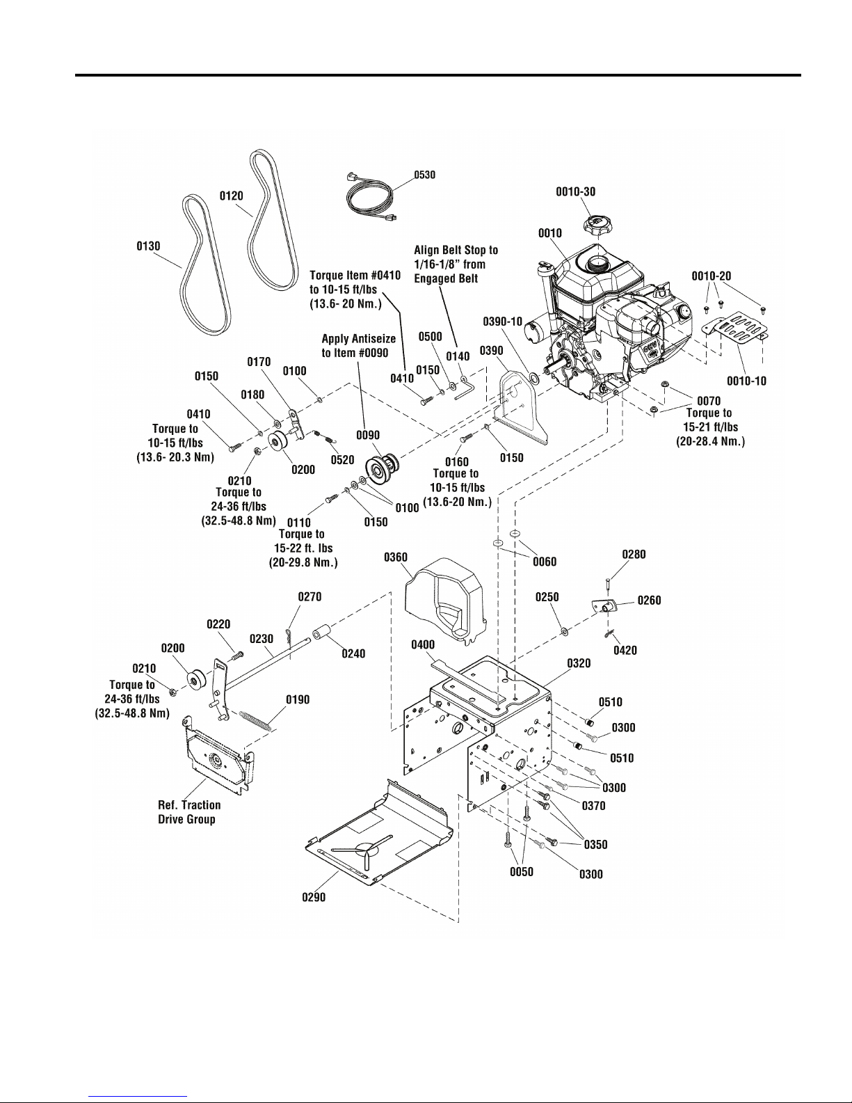
Engine Group
NOTE: Unless noted otherwise,
use the standard hardware torque
specification chart.
CRAFTSMAN 24" C950-52122-0
PTS - 2

Engine Group
PART NO. DESCRIPTIONREF NO QTY.
CRAFTSMAN 24" C950-52122-0
* ENGINE, 8TP Briggs & Stratton, Snow Series (Engine Model: 12A113-0154-E8) 0010 12A113-0154-E8 1
GUARD, Muffler, Plate 0010-10 797003 1
SCREW, Hex Head, Muffler Guard 0010-20 699234 3
* CAP, Fuel 0010-30 795027 1
BOLT, 5/16-18 x 1-1/2" Short Square Neck Carriage GR 5 0050 1931337SM 4
PUSHNUT, 1/4 0060 028X76MA 4
NUT, Hex Flange, ESNA, 5/16-18 0070 1739305YP 4
PULLEY, Engine 0090 1501109MA 1
WASHER, 5/16 0100 1919381SM 3
CAPSCREW, Hex Head, 5/16-24 x 1-1/4, G5 0110 1921982SM 1
V-BELT, Traction Drive, 3L 33.13 0120 1733324SM 1
BELT, Auger 0130 1751417YP 1
BELT GUIDE 0140 1739070YP 1
LOCKWASHER, Spring, 5/16 0150 1917356SM 4
CAPSCREW, Hex Head, 5/16-24 x 3/4, G5 0160 1921515SM 1
BRACKET, Idler 0170 1501112YZMA 1
BUSHING, Idler Bracket 0180 1501065MA 1
SPRING, External, Auger 7/16 ID x 5-1/8 x 3/4 W 0190 165X159MA 1
IDLER, Plastic Ball Bearing 0200 1502120MA 2
NUT, Hex Centerlock Jam, 3/8-16 0210 1960251SM 2
CARRIAGE BOLT, 3/8-16 x 1-1/4 0220 585781MA 1
IDLER ASSEMBLY, Auger 0230 1501226YZMA 1
SPACER, Auger Idler 0240 1501200MA 1
WASHER, 1/2” Flat 0250 1960027SM 1
ARM, Control 0260 1733451SM 1
PIN, Hair 3/8 x 1-5/8 0270 0031X6MA 1
PIN, Clevis 0280 1736381YP 1
PANEL, Bottom 0290 1740906ASM 1
CAPSCREW, Hex Washer Head, Taptite, 1/4-20 x 5/8 0300 1927429SM 10
FRAME BOX 0320 1751698BNYP 1
CAPSCREW, Hex Washer Head, Taptite, 5/16-18 x 3/4 0350 1664847SM 6
COVER, Belt 0360 1751525YP 1
SCREW, Hex Washer Head, 1/4-20 x 3/4 0370 1751355YP 2
PLATE, Seal 0390 1733868BZYP 1
SEAL, Foam 0390-10 1733898SM 1
STRIP, Seal 0400 1750172YP 1
BOLT, Hex 5/16-24 x 1 0410 910828MA 2
PIN, Cotter, Self Locking, 1/4" 0420 7023590SM 1
WASHER, Flat, 3/8 x 7/8 0500 7091528SM 1
THREADED INSERT, Open End, 5/16-18 0510 1752526YP 4
SPRING, Extension, Idler 0520 165X164MA 1
CORD, Electric 0530 6219MA 1
Footnotes
Note* See your local Briggs & Stratton distributor for parts and service.
PTS - 3
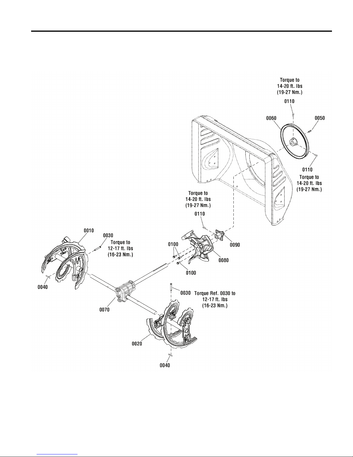
Auger Drive Group
NOTE: Unless noted otherwise,
use the standard hardware torque
specification chart.
CRAFTSMAN 24" C950-52122-0
PTS - 4
 Loading...