

Craftsman C944.526460 Owner's Manual

I
Sears
I
,
owner s
manual
MODEL NO.
C944.526460
CAUTION:
Read RULES for
Safe OPERATION
and INSTRUCTIONS
Carefully
CRAFTSMAN
22", 7 H.P. SNOW THROWER
• Assembly
• Operating
• Maintenance
• Repair Parts
IMPORTANT
RULES FOR SAFE OPERATION
TRAINING
1. Read the operating and service instruction manual
carefully. Be thoroughly familiar with the controls
and the proper use of the equipment. Know how to
stop the unit and disengage the controls quickly.
2. Never allow children to operate the equipment.
Never allow adults to operate the equipment with-
out proper instruction.
3. Keep the area of operation clear of all persons,
particularly small children and pets.
4. Exercise caution to avoid slipping or falling, espec-
ially when operating in reverse.
PREPARATION
1. Thoroughly inspect the area where the equipment
is to be used and remove all doormats, sleds, boards,
wires, and other foreign objects.
2. Disengage all clutches and shift into neutral before
starting the engine.
3. Do not operate the equipment without wearing
adequate winter outer garments. Wear footwear
which will improve footing on slippery surfaces. Do
not wear long scarfs or loose fitting clothing which
may become entangled in machinery.
4. Handle fuel with care; it is highly flammable.
(a) Use an approved fuel container.
(b) Never add fuel to a running engine or hot engine.
(c) Fill fuel tank outdoors with extreme care. Never
fill fuel tank indoors.
(d) Replace gasoline cap securely and wipe up
spilled fuel.
5. Use a grounded three-wire plug-in for all units
equipped with electric starting motors.
6. Adjust the impeller housing height to clear gravel
or crushed rock surface.
7. Never attempt to make any adjustments while the
engine is running (except where specifically recom-
mended by manufacturer).
8. Let engine and machine adjust to outdoor tempera-
tures before starting to clear snow.
OPERATION
1. Do not put hands or feet near or under rotating
parts. Keep clear of the discharge opening at all
times.
2. Exercise extreme caution when operating on or
crossing gravel drives, walks, or roads. Stay alert
for hidden hazards or traffic. Do not carry pass-
engers.
3. After striking a foreign Object, stop the engine,
remove the wire from the spark plug, thoroughly
inspect the snow thrower for any damage, and .re-
pair the damage before restarting and operating
the snow thrower.
4. If t:le unit should 'start to vibrate abnormally, stop
the engine and check immediately for the cause.
Vibration is generally a warning of trouble.
5. Stop the engine whenever you leave the operating
position, before unclogging the impeller housing
or discharge guide, and when making any repairs,
adjustments, or inspections.
6. Take all possible precautions when leaving the
unit: shift into neutral, disengage the drive (prim-
ary) clutch, shut off the engine, and remove the
key.
7. When cleaning, repairing, or inspecting, make
certain the impeller and all moving parts have
stopped. Disconnect the spark plug wire, and keep
the wire away from the plug to prevent accidental
starti ng. Disconnect the cord on electric starter
motor.
8. Do not run the engine indoors, except when start-
ing the engine and for transporting the snow
thrower in or out of the building. Open the outside
doors; exhaust fumes are dangerous.
9. Do not clear snow across the face of slopes.
Exercise extreme caution when changing direction
on slopes. Do not attempt to clear steep slopes.
10. Never operate the snow thrower without proper
guards, plates, or other safety protective devices
in place.
11. Never operate the snow thrower near glass en-
closures, automobiles, window wells, drop ofts, etc.
without proper adjustment of the snow discharge
angle. Keep children and pets away.
12. Do not overload the machine capacity by attempt-
ing to clear snow at too fast a rate.
13. Never operate the machine at high transport
speeds on slippery surfaces. Use care when
backing.
14. Never direct discharge at bystanders or allow
anyone in front of the unit.
15. Disengage power to the impeller when snow
thrower is transported or not in use.
16. Use only attachments and accessories approved
by the manufacturer of snow thrower (such as
electric starter kits, cabs, etc.).
17. Never operate the snow thrower without g.ood vis-
ibility or light. Always be sure of your footing, and
keep a firm hold on the handles. Walk; never run.
MAINTENANCE AND STORAGE
1. Check shear bolts, engine mounting bolts, etc. at
frequent intervals for proper tightnes~ .to be sure
the equipment is in safe working conditIOn.
2. Never store the machine with fuel in the fuel tank
inside a building where open flame or spar~s a:e
present. Allow the engine to cool before storing In
any enclosure.
3. Always refer to owner's manual in.structions for
important details if the snow throwerISto be stored
for an extended period.
4. Run the machine a few minutes after throwing snow
to prevent freeze up of the impeller.
craftsman quality snow removal equipment
For one year from purchase date, Simpsons-Sears will replace, Free of Charge,
any part or parts including the engine, found, upon examination to be defective
under normal use and service, by reason of defects in material and workman-
ship. The warranty is void if the unit has been the subject of misuse.
A modern low cost maintenance agreement is available on this product, to
extend the guarantee. Contact your nearest Simpsons-Sears Store.
Compliance with radio interference regulations certified, replace spark plug
with resistor spark plug only.
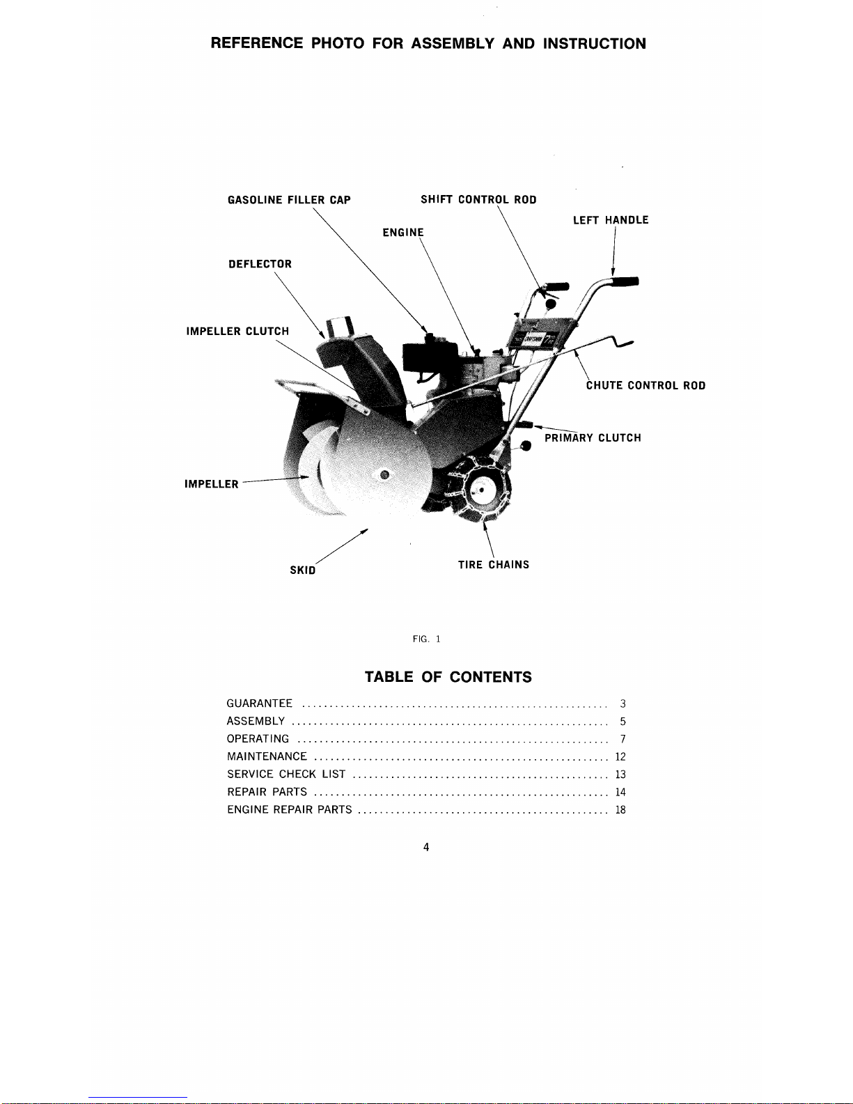
DEFLECTOR
IMPEllERClUT\
LEFT HANDLE
J
~
~. PRIMARY CLUTCH
/
SKID
GUARANTEE 3
ASSEMBLY 5
OPERATING 7
MAINTENANCE 12
SERVICE CHECK LIST 13
REPAIR PARTS 14
ENGINE REPAIR PARTS 18

For shipping purposes, the handles and operating
controls of your snow thrower have not been assembled
to the unit. The carton of parts, in which this owner's
manual was found, contains all components and hard-
ware necessary to complete the assembly.
NOTE: The terms Left Hand (L.H.) and Right Hand
(R.H). refer to your left and right hands when you
stand in the operator's position behind the unit.
ATTENTION: FOR EASIER ASSEMBLY, TILT SNOW
THROWER FORWARD SO THAT IT RESTS ON SAFETY
BAR AS SHOWN (FIG. 2).
HANDLE ASSEMBLY
1. Slide lower two holes of R.H. handle over weld
screws on R.H. side of snow thrower chassis (Fig.
3). Assemble formed washer to upper weld screw,
and secure handle with two
3fs
-16 flange nuts.
Tighten finger tight only.
2. Assemble L.H. handle to snow thrower in same
manner.
~ RIGHT HANDLE
~.:y /
CHASSIS
r'
0
FORMED WASHER
!
~I
~~~~f*
c'
rn~
\ "'"· -J
\ WELD SCREWS
@
FLANGE NUTS
3. Assemble handle plate to handles (Fig. 4), using
four 5/16-18 x 1
¥.i
carriage bolts and four 5/16-18
flange nuts. Tighten securely.
4. Tighten four
3fs
-16 flange nuts securely against
lower end of both handles (Fig. 3).
FIG. 4
SHIFT CONTROL ROD ASSEMBLY (Fig. 5 to 8)
1. Assemble one
3fs
-16 flange nut (A) to end of shift
control rod having the longest threaded portion.
Flange of nut must face toward threaded end of
shift control rod as shown (Fig. 5 and 6). Thread
the nut the full length of the threads.
TRANSMISSION CONTROL BRACKET
(C)
'Z' SLOT
HANDLE PLATE
LOCATING PIN
SHIFT CONTROL ROD
SHIFT CONTROL ROD________ A
TRANSMISSION CONTROL BKT. /
TRANSMISSION ~..... ~~
SHIFT~~.
/
~~\
~
~
\\.
FIG. 6
2. Position other end of shift control rod up through
slot in top of handle plate, so that locating pin on
rod engages the "Z" slot in handle plate (Fig. 5).
Swing transmission control bracket upwards (Fig.
6), and insert lower end of shift control rod into
hole in transmission control bracket (Fig. 5 and 6).
3. Assemble one
3fs
-16 flange nut (B), with flange up,
to lower end of shift control rod (Fig. 6). Do not
tighten nut.
4. IMPORTANT: Position transmission shift lever in
neutral position (Fig. 7), approximately in the centre
of slot in rear cover. Rotate wheels of unit; wheels
should turn freely if neutral has been obtained. Shift
lever may have to be moved up or down slightly
from centre of slot in order to obtain neutral.
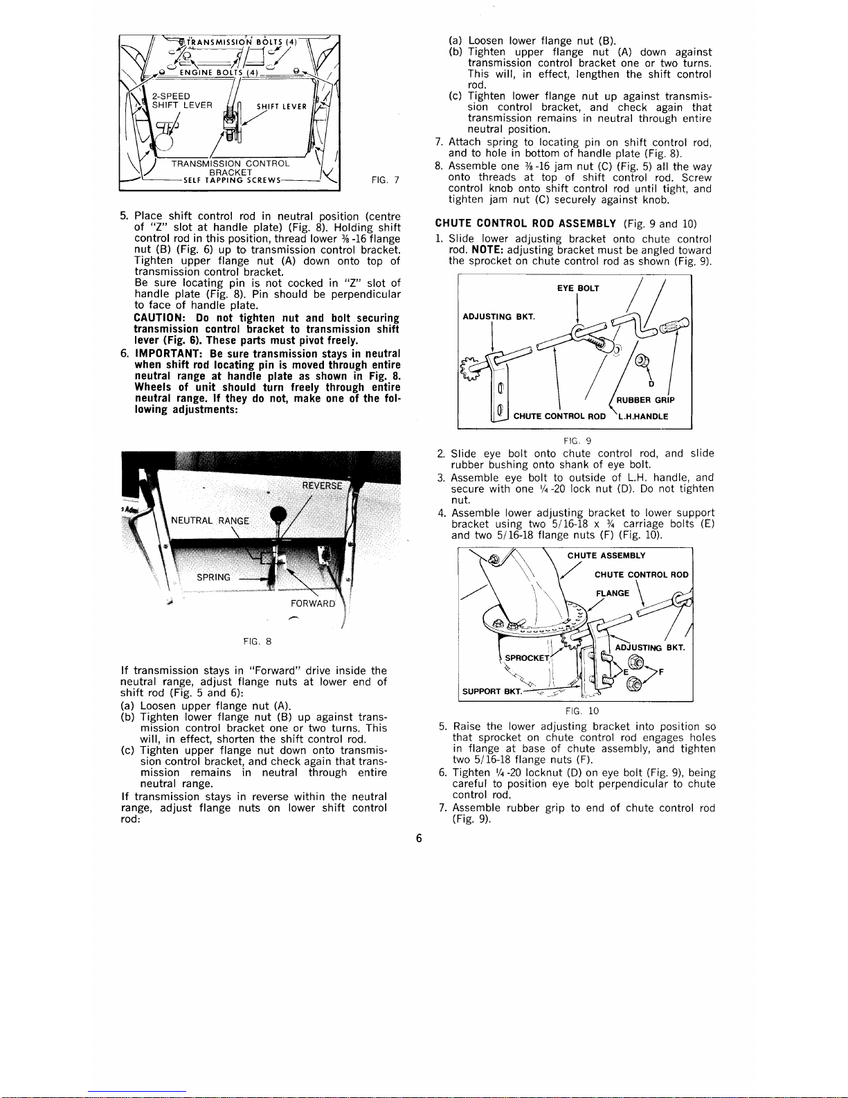
TRANSMISSION BOLTS (4)
;J2~==li
Q;:;
~;'~;E::~Bi~IFT":ER
L
TRANSMISSION CONTROL
BRACKET
SElF TAPPING SCREWS
5. Place shift control rod in neutral position (centre
of
"l"
slot at handle plate) (Fig. 8). Holding shift
control rod in this position, thread lower
3fB
-16 flange
nut (B) (Fig. 6) up to transmission control bracket.
Tighten upper flange nut (A) down onto top of
transmission control bracket.
Be sure locating pin is not cocked in
"l"
slot of
handle plate (Fig. 8). Pin should be perpendicular
to face of handle plate.
CAUTION: Do not tighten nut and bolt securing
transmission control bracket to transmission shift
lever (Fig. 6). These parts must pivot freely.
6. IMPORTANT: Be sure transmission stays in neutral
when shift rod locating pin is moved through entire
neutral range at handle plate as shown in Fig. 8.
Wheels of unit should turn freely through entire
neutral range. If they do not, make one of the fol-
lowing adjustments:
If transmission stays in "Forward" drive inside the
neutral range, adjust flange nuts at lower end of
shift rod (Fig. 5 and 6):
(a) Loosen upper flange nut (A).
(b) Tighten lower flange nut (B) up against trans-
mission control bracket one or two turns. This
will, in effect, shorten the shift control rod.
(c) Tighten upper flange nut down onto transmis-
sion control bracket, and check again that trans-
mission remains in neutral through entire
neutral range.
If transmission stays in reverse within the neutral
range, adjust flange nuts on lower shift control
rod:
(a) Loosen lower flange nut (B).
(b) Tighten upper flange nut (A) down against
transmission control bracket one or two turns.
This will, in effect, lengthen the shift control
rod.
(c) Tighten lower flange nut up against transmis-
sion control bracket, and check again that
transmission remains in neutral through entire
neutral position.
7. Attach spring to locating pin on shift control rod,
and to hole in bottom of handle plate (Fig. 8).
8. Assemble one
3/B
-16 jam nut (C) (Fig. 5) all the way
onto threads at top of shift control rod. Screw
control knob onto shift control rod until tight, and
tighten jam nut (C) securely against knob.
CHUTE CONTROL ROD ASSEMBLY (Fig. 9 and 10)
1. Slide lower adjusting bracket onto chute control
rod. NOTE: adjusting bracket must be angled toward
the sprocket on chute control rod as shown (Fig. 9).
EYE BOLT
/1
ADJUSTING BKT.
1 ~ / .
1 ~~~
\
/
~ ~
I rn
I
ffi
CHUTE CONTROL ROD L.H.HANDLE
FIG. 9
2. Slide eye bolt onto chute control rod, and slide
rubber bushing onto shank of eye bolt.
3. Assemble eye bolt to outside of L.H. handle, and
secure with one
1/4
-20 lock nut
(0).
Do not tighten
nut.
4. Assemble lower adjusting bracket to lower support
bracket using two 5/16-18 x%carriage bolts (E)
and two 5/16-18 flange nuts (F) (Fig. 10).
SPROCKE~Y
,)1\
SUPPORT BKT. ". ~
FIG. 10
5. Raise the lower adjusting bracket into position
SO
that sprocket on chute control rod engages holes
in flange at base of chute assembly, and tighten
two 5/16-18 flange nuts (F).
6. Tighten
1/4
-20 locknut (D) on eye bolt (Fig. 9), being
careful to position eye bolt perpendicular to chute
control rod.
7. Assemble rubber grip to end of chute control rod
(Fig. 9).
CHECKING CHUTE OPERATION (Fig. 10)
If sprocket teeth tend to jam in holes in flange at
base of chute assembly, lower the sprocket slightly by
loosening the two 5/16-18 flange nuts (F) and lowering
the lower adjusting bracket.
If sprocket teeth skip across holes in flange, raise the
sprocket by loosening two nuts (F) and raising the
lower adjusting bracket slightly. Tighten nuts (F)
securely.
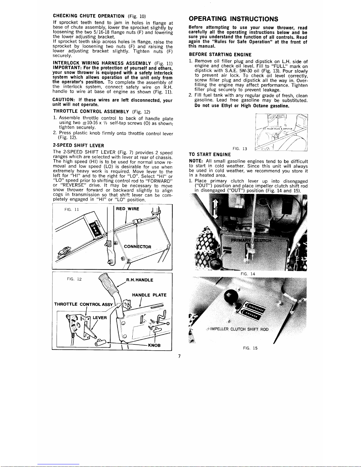
INTERLOCK WIRING HARNESS ASSEMBLY (Fig. 11)
IMPORTANT: For the protection of yourself and others,
your snow thrower is equipped with a safety interlock
system which allows operation of the unit only from
the operator's position. To complete the assembly of
the interlock system, connect safety wire on R.H.
handle to wire at base of engine as shown (Fig. 11).
CAUTION: If these wires are left disconnected, your
unit will not operate.
THROTTLE CONTROL ASSEMBLY (Fig. 12)
1. As~emble throttle control to back of handle plate
uSing two#10-16 x
112
self-tap screws
(0)
as shown'
tighten securely. '
2. Press plastic knob firmly onto throttle control lever
(Fig. 12).
2-SPEED SHIFT LEVER
The 2-SPEED SH IFT LEVER (Fig. 7) provides 2 speed
ranges which are selected with lever at rear of chassis.
The high speed (H I) is to be used for norma I snow re-
moval and low speed (LO) is desirable for use when
extremely heavy work is required. Move lever to the
left for "H I" and to the right for "LO". Select "H I" or
"LO" speed prior to shifting control rod to "FORWARD"
or "REVERSE" drive. It may be necessary to move
snow thrower forward or backward slightly to align
cogs in transmission so that shift lever can be com-
pletely engaged in "HI" or "LO" position.
Before attempting to use your snow thrower, read
carefully all the operating instructions below and be
sure you understand the function of all controls. Read
again the "Rules for Safe Operation" at the front of
this manual.
BEFORE STARTING ENGINE
1. Remove oil filler plug and dipstick on L.H. side of
engine and check oil level. Fill to "FULL" mark on
dipstick with S.A.E. 5W-30 oil (Fig. 13). Pour slowly
to prevent air lock. To check oil level correctly,
screw filler plug and dipstick all the way in. Over-
filling the engine may affect performance. Tighten
filler plug secur:ely to prevent leakage.
2. Fill fuel tank with any regular grade of fresh, clean
gasoline. Lead free gasoline may be substituted.
Do not use Ethyl or High Octane gasoline.
J
~.'\ll'lill
_rT
---------:::l1
_____..... Oll Flll' ....R PlU .." • O.IPST ..'.~'. .
/' ;Y'
/_ _ -"l
, ; .'=:i2J;Y' '.
o
'~/?
~"'.//-
/
FIG. 13
TO START ENGINE
NOTE: All small gasoline engines tend to be difficult
to start in cold weather. Since this unit will always
be used in cold weather, we recommend you store it
in a heated area.
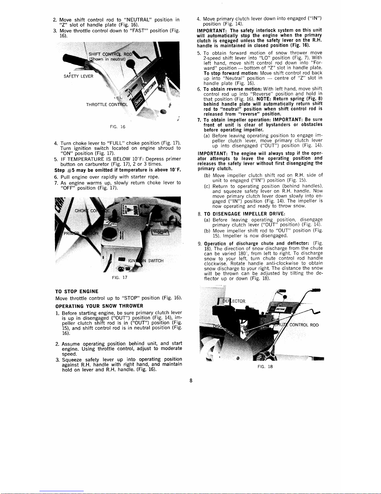
1. Place primary clutch lever up into disengaged
("OUT") position and place impeller clutch shift rod
in disengaged ("OUT") position (Fig. 14 and 15).
2. Move shift control rod to "NEUTRAL" position in
"Z" slot of handle plate (Fig. 16).
3. Move throttle control down to "FAST'" position (Fig.
16).
4. Turn choke lever to "FULL" choke position (Fig. 17).
Turn ignition switch located on engine shroud to
"ON" position (Fig. 17).
5. IF TEMPERATURE IS BELOW loaF: Depress primer
button on carburetor (Fig. 17), 2 or 3 times.
Step #5 may be omitted if temperature is above loaF.
6. Pull engine over rapidly with starter rope.
7. As engine warms up, slowly return choke lever to
"OFF" position (Fig. 17).
TO STOP ENGINE
Move throttle control up to "STOP" position (Fig. 16).
OPERATING YOUR SNOW THROWER
1. Before starting engine, be sure primary clutch lever
is up in disengaged ("OUT") position (Fig. 14), im-
peller clutch shift rod is in ("OUT") position (Fig.
15), and shift control rod is in neutral position (Fig.
16).
2. Assume operating position behind unit, and start
engine. Using throttle control, adjust to moderate
speed.
3. Squeeze safety lever up into operating position
against R.H. handle with right hand, and maintain
hold on lever and R.H. handle. (Fig. 16).
4. Move primary clutch lever down into engaged ("IN")
position (Fig. 14).
IMPORTANT: The safety interlock system on this unit
will automatically stop the engine when the primary
clutch is engaged unless the safety lever on the R.H.
handle is maintained in closed position (Fig. 16).
5. To obtain forward motion of snow thrower move
2-speed shift lever into "La" position (Fig. 7). With
left hand, move shift control rod down into "For-
ward" position - bottom of "Z" slot in handle plate.
To stop forward motion: Move shift control rod back
up into "Neutral" position - centre of "Z" slot in
handle plate (Fig. 16).
6. To obtain reverse motion: With left hand, move shift
control rod up into "Reverse" position and hold in
that position (Fig. 16). NOTE: Return spring (Fig. 8)
behind handle plate will automatically return shift
rod to "neutral" position when shift control rod is
released from "reverse" position.
7. To obtain impeller operation: IMPORTANT: Be sure
front of unit is clear of bystanders or obstacles
before operating impeller.
(a) Before leaving operating position to engage im-
peller clutch lever, move primary clutch lever
up into disengaged ("OUT") position (Fig. 14).
IMPORTANT: The engine will always stop if the oper-
ator attempts to leave the operating position and
releases the safety lever without first disengaging the
primary clutch.
(b) Move impeller clutch shift rod on R.H. side of
unit to engaged ("IN") position (Fig. 15).
(c) Return to operating position (behind handles),
and squeeze safety lever on R.H. handle. Now
move primary clutch lever down slowly into en-
gaged ("IN") position (Fig. 14). The impeller is
now operating and ready to throw snow.
8. TO DISENGAGE IMPELLER DRIVE:
(a) Before leaving operating position, disengage
primary clutch lever ("OUT" position) (Fig. 14).
(b) Move impeller shift rod to "OUT" position (Fig.
15). Impeller is now disengaged.
9. Operaticn of discharge chute and deflector: (Fig.
18). The direction of snow discharge from the chute
can be varied 180°, from left to right. To discharge
snow to your left, turn chute control rod handle
clockwise. Rotate handle anti-clockwise to obtain
snow discharge to your right. The distance the snow
will be thrown can be adjusted by tilting the de-
flector up or down (Fig. 18).
 Loading...