

Page 1
Instruction Manual
32cc/1.9 cu.in. 2-Cycle
GASOLINE BRUSHWACKER ®
Model No.
0944.512561
• Safety
• Assembly
• Operation
• Maintenance
• Parts List
• Franqais
WARNING:
Read and follow all Safety Rules and Operating
Instructions before first use of this product.
For answers to your questions about this product:
Call 7 am-7 pm, Mon.-Sat., or 10 am-7 pm, Sun.
1-800-235-5878 _.o._ listed are Central Time)
Sears Canada, Inc., Toronto, Ontario M5B 2B8
530163724 4/23/03
Page 2
Warranty Statement 2 Storage 20
Safety Rules 2 Troubleshooting Table 21
Assembly 5 Emissions Statement 22
Operation 9 Parts List 24
Maintenance 18 French 26
Service & Adjustments 19 Parts and Ordering BackCover
LIMITED TWO (2_ YEAR WARRANTY ON CRAFTSMAN ® GAS POWERED
WEEDWACKER _ LINE TRIMMER
For two (2) years from the date of purchase, Sears Canada, ]nc., will repair or
replace free of charge at Sears option parts which are defective as a result of
material or workmanship.
COMMERCIAL OR RENTAL USE:
Warranty on Gas Weedwacker will be 90 days from the date of purchase if used
for commercial or rental purposes.This warranty does not cover:
1. Spark plugs, filter, line, spool, starter rope, and blade.
2. Damages to the motor of the unit when operated without the proper fuel
mixture (see manual).
Warranty service is available by returning the Weedwacker to the nearest Sears Ser-
vice Centre/Department in Canada. This warranty applies only while this product is in
use in Canada.
This warranty is in addition to any statutory warranty and does not exclude or limit
legal rights you may have but shall run concurrently with applicable provincial
legislation. Furthermore, some provinces do NOT allow limitations on how long an
implied warranty will last, so the above limitations may not apply to you.
Sears Canada, Inc., Toronto, Ontario M5B 2B8
_WARNING: When using gar-
dening appliances, basic safety pre-
cautions must always be followed to
reduce the risk of fire and serious
injury. Read and follow all instructions.
DANGER: This power tool can
be dang.erous! This unit can cause se-
rious InjurY including amputation or
blindness to the operator and others.
The warnings and safety instructions
in this manual must be followed to pro-
vide reasonable safety and efficiency
in using the unit. The operator is re-
sponsible for following the warnings
and instructions in this manual and on
the unit. Read the entire instruction
manual before assembling and using
the unit! Restrict the use of this unit to
persons who read, understand, and
follow the warnings and instructions in
this manual and on the unit. Never al-
low children to operate this unit.
INSTRUCTION SAFETY INFORMATION
MANUAL ON THE UNIT
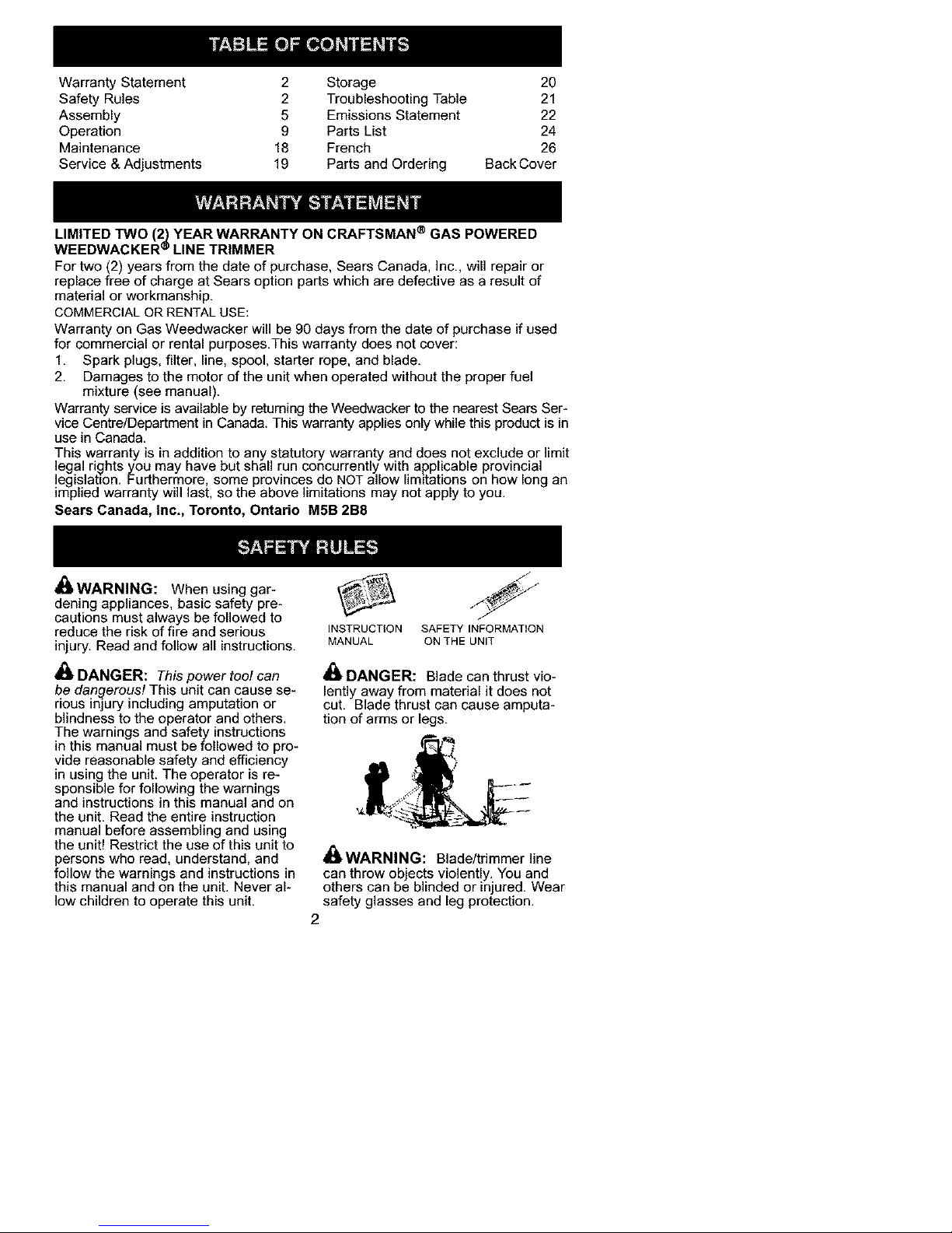
DANGER: Blade can thrust vio-
lently away from material it does not
cut. Blade thrust can cause amputa-
tion of arms or legs.
_I_WARNING: Blade/trimmer line
can throw ob ects violently. You and
others can be b nded or njured. Wear
safety glasses and leg protection.
2
Page 3
ALWAYSWEAR:I _,9_l.r
Eye_I_ Thrown_r
ProtectionIr;"l Objectsm
11 LegGuards_-°_..!
Boots -/ lL
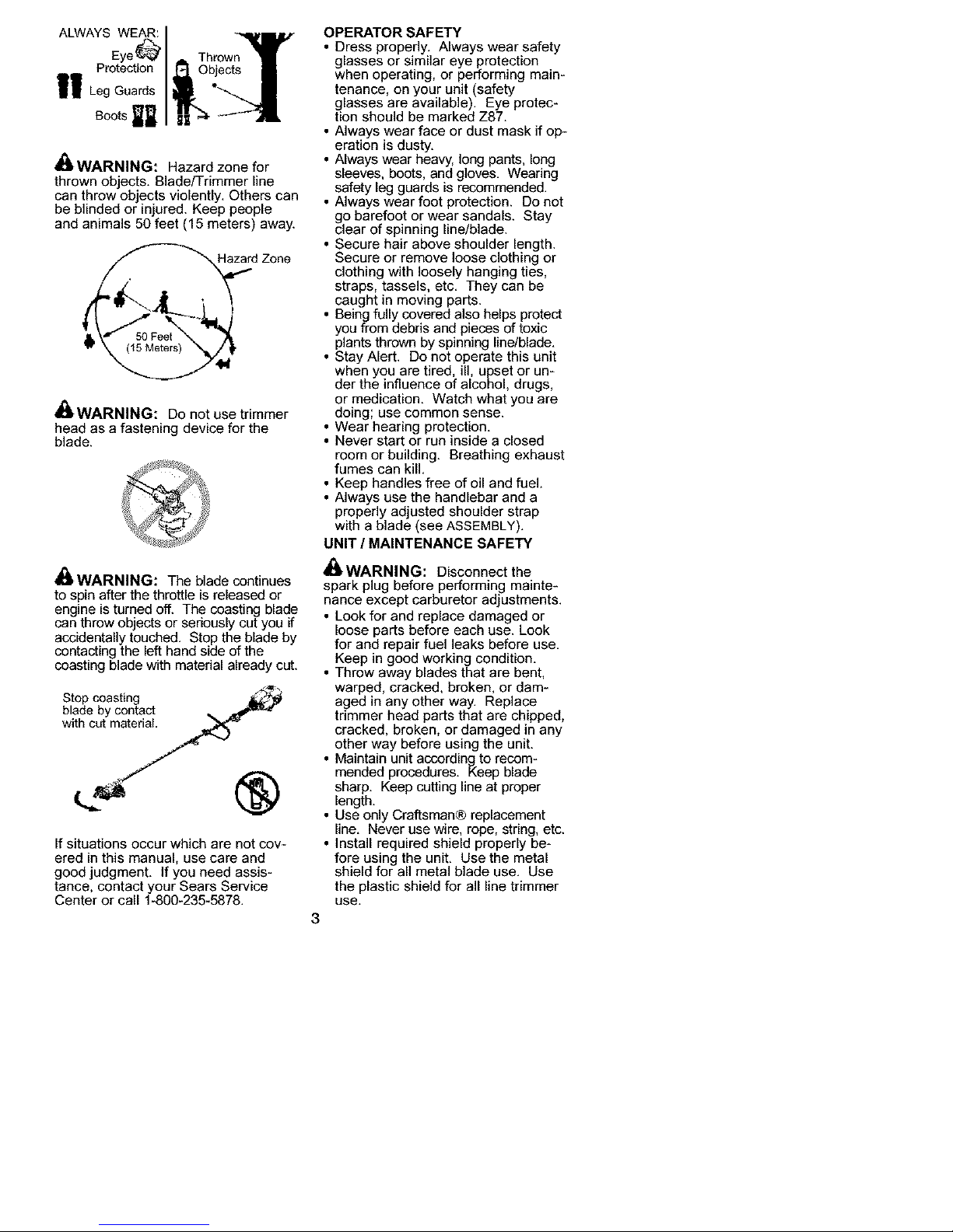
_I_WARNING: Hazard zone for
thrown objects. Blade/Trimmer line
can throw ob ects violently. Others can
be b nded or nured. Keep peop e
and animals 50 feet (15 meters) away.
d Zone
_l_ WARNING: Do not use trimmer
head as a fastening device for the
blade.
_I_WARNING: The blade continues
to spin after the throttle is released or
engine is turned off. The coasting blade
can throw objects or seriously cut you if
accidentally touched, Stop the blade by
contacting the left hand side of the
coasting blade with material already cut.
Stop coasting _
blade by contact _,_ ,e_m'_l
with cut material
If situations occur which are not cov-
ered in this manual, use care and
good judgment. If you need assis-
tance, contact your Sears Service
Center or call 1-800-235-5878.
OPERATOR SAFETY
• Dress properly. Always wear safety
glasses or similar eye protection
when operating, or performing main-
tenance, on your unit (safety
glasses are available). Eye protec-
tion should be marked Z87.
• Always wear face or dust mask if op-
eration is dusty.
• Always wear heavy, long pants, long
sleeves, boots, and gloves. Wearing
safety leg guards is recommended.
• Always wear foot protection. Do not
go barefoot or wear sandals. Stay
clear of spinning line/blade.
• Secure hair above shoulder length.
Secure or remove loose clothing or
clothing with loosely hanging ties,
straps, tassels, etc. They can be
caught in moving parts.
• Being fully covered also helps protect
you from debris and pieces of toxic
plants thrown by spinning line/blade.
• Stay Alert. Do not operate this unit
when you are tired, ill, upset or un-
der the influence of alcohol, drugs,
or medication. Watch what you are
doing; use common sense.
• Wear hearing protection.
• Never start or run inside a closed
room or building. Breathing exhaust
fumes can kill.
• Keep handles free ofoil and fuel.
• Always use the handlebar and a
properly adjusted shoulder strap
with a blade (see ASSEMBLY).
UNIT / MAINTENANCE SAFETY
_I_i,WARNING: Disconnect the
spark plug before performing mainte-
nance except carburetor adjustments.
• Look for and replace damaged or
loose parts before each use. Look
for and repair fuel leaks before use.
Keep in good working condition.
• Throw away blades that are bent.
warped, cracked, broken, or dam-
aged in any other way. Replace
trimmer head parts that are chipped,
cracked, broken, or damaged in any
other way before using the unit.
• Maintain unit according to recom-
mended procedures. Keep blade
sharp. Keep cutting line at proper
length.
• Use only Craftsman® replacement
line. Never use wire, rope, string, etc.
• Install required shield properly be-
fore using the unit. Use the metal
shield for all metal blade use. Use
the plastic shield for all line trimmer
use.
3
Page 4
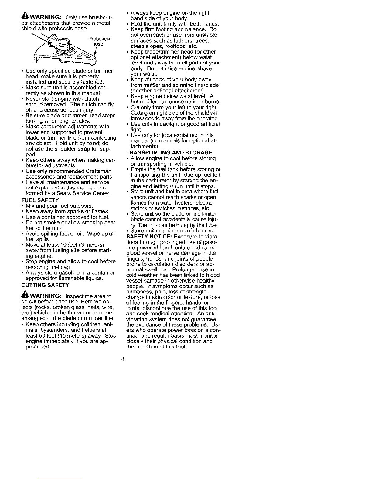
,_ WARNING: Only use brushcut-
ter attachments that provide a metal
shield with proboscis nose.
se
° Use only specified blade or trimmer
head; make sure it is properly
installed and securely fastened.
° Make sure unit is assembled cor-
rectly as shown in this manual.
° Never start engine with clutch
shroud removed. The clutch can fly
off and cause serious injury.
* Be sure blade or trimmer head stops
turning when engine idles.
* Make carburetor adjustments with
lower end supported to prevent
blade or trimmer line from contacting
any object. Hold unit by hand; do
not use the shoulder strap for sup-
port.
* Keep others away when making car-
buretor adjustments.
* Use only recommended Craftsman
accessories and replacement parts.
* Have all maintenance and service
not explained in this manual per-
formed by a Sears Service Center.
FUEL SAFETY
* Mix and pour fuel outdoors.
* Keep away from sparks or flames.
* Use a container approved for fuel.
* Do not smoke or allow smoking near
fuel or the unit.
* Avoid spilling fuel or oil. Wipe up all
fuel spills.
, Move at least 10 feet (3 meters)
away from fueling site before start-
ing engine.
, Stop engine and allow to cool before
removing fuel cap.
, Always store gasoline in a container
approved for flammable liquids.
CUTTING SAFETY
£*.
all.WARNING: Inspect the area to
be cut before each use. Remove ob-
jects (rocks, broken glass, nails, wire,
etc.) which can be thrown or become
entangled in the blade or trimmer line.
* Keep others including children, ani-
mals, bystanders, and helpers at
least 50 feet (15 meters) away. Stop
engine immediately if you are ap-
proached.
• Always keep engine on the right
hand side of your body.
• Hold the unit firmly with both hands.
• Keep firm footing and balance. Do
not overreach or use from unstable
surfaces such as ladders, trees,
steep slopes, rooftops, etc.
• Keep blade/trimmer head (or other
optional attachment) below waist
level and away from all parts of your
body. Do not raise engine above
your waist.
• Keep all parts of your body away
from muffler and spinning line/blade
(or other optional attachment).
• Keep engine below waist level. A
hot muffler can cause serious burns.
• Cut only from your left to your right.
Cutting on right side of the shield will
throw debris away from the operator.
• Use only in daylight or good artificial
light.
• Use only for jobs explained in this
manual (or manuals for optional at-
tachments).
TRANSPORTING AND STORAGE
• Allow engine to cool before storing
or transporting in vehicle.
• Empty the fuel tank before storing or
transporting the unit. Use up fuel left
in the carburetor by starting the en-
gine and letting it run until it stops.
• Store unit and fuel in area where fuel
vapors cannot reach sparks or open
flames from water heaters, electric
motors or switches, furnaces, etc.
• Store unit so the blade or line limiter
blade cannot accidentally cause inju-
ry. The unit can be hung by the tube.
• Store unit out of reach of children.
SAFETY NOTICE: Exposure to vibra-
tions through prolonged use of gaso-
line powered hand tools could cause
blood vessel or nerve damage in the
fingers, hands, and joints of people
prone to circulation disorders or ab-
normal swellings. Prolonged use in
cold weather has been linked to blood
vessel damage in otherwise healthy
people. If symptoms occur such as
numbness, pain, loss of strength,
change in skin color or texture, or loss
of feeling in the fingers, hands, or
joints, discontinue the use of this tool
and seek medical attention. An anti-
vibration system does not guarantee
the avoidance of these problems. Us-
ers who operate power tools on a con-
tinual and regular basis must monitor
closely their physical condition and
the condition of this tool.
4
Page 5
SPECIAL NOTICE: This unit is not
equipped with a temperature limiting
muffler and spark arresting screen
which meets the requirements of Cali-
fornia Codes 4442 and 4443. All U.S.
forest land and the states of California,
Idaho, Maine, Minnesota, New Jersey,
Oregon, and Washington require by law
that many internal combustion engines
CARTON CONTENTS
be equipped with a spark arrestor
screen. If you operate in a locale where
such regulations exist, you are legally
responsible for installing and maintain-
ing the operating condition of these
parts. Failure to do so is a violation of
the law. If a spark arresting screen is
required in your area, contact your
Sears Service Centre for the correct kit.
Check carton contents against the fol-
lowing list.
Model C944.512561
Powerhead
Brushcutter attachment
Blade shield screws (4)
Cupped washer
Large nut for installing blades
Hex wrench
Metal shield
Plastic shield
Shoulder strap with warning
4-point weed blade
Trimmer head (assembled on unit)
Handlebar (assembled on unit)
Wing nut (screwed onto shield)
Container of oil
Examine parts for damage. Do not
use damaged parts.
NOTE: If you need assistance or find
parts missing or damaged, call
1-800-235-5878.
It is normal for the fuel filter to rattle in
the empty fuel tank.
Finding fuel or oil residue on muffler is
normal due to carburetor adjustments
and testing done by the manufacturer.
ASSEMBLY
_ WARNING: If received as-
sembled, repeat all steps to ensure
your unit is properly assembled and all
fasteners are secure.
INSTALLING BRUSHCUTTER AT-
TACHMENT
CAUTION: When installing brushcut-
ter attachment, place the unit on a flat
surface for stability.
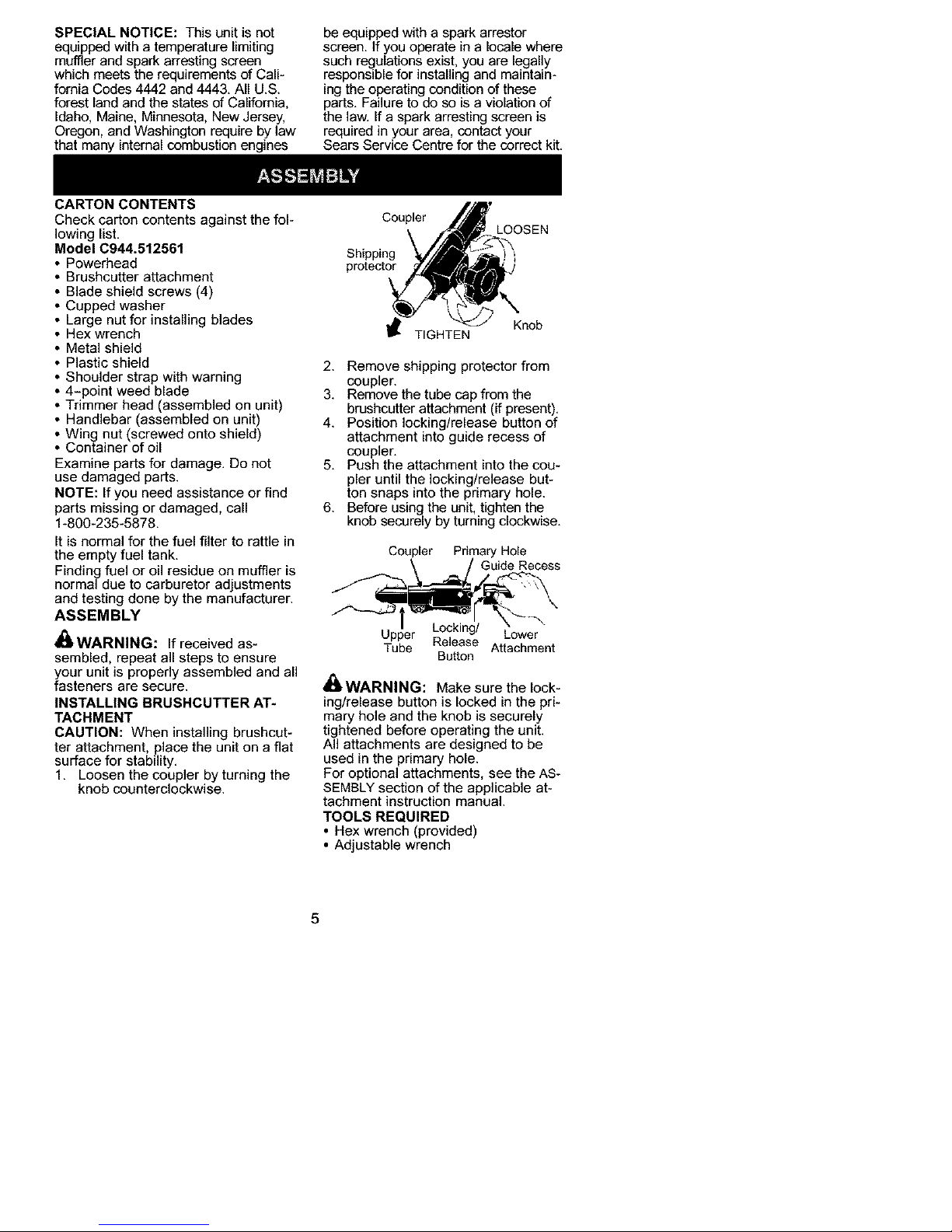
1. Loosen the coupler by turning the
knob counterclockwise.
Coupler
LOOSEN
Shipping
protector
Knob
TIGHTEN
2. Remove shipping protector from
coupler.
3. Remove the tube cap from the
brushcutter attachment (if present).
4. Position locking/release button of
attachment into guide recess of
coupler.
5. Push the attachment into the cou-
pler until the locking/release but-
ton snaps into the primary hole.
6. Before using the unit, tighten the
knob securely by turning clockwise.
Cot_ F i/rr_rYidHOl_ecess
UTPuPberRelease AtL°(_emrent
Button
_1_WARNING: Make sure the lock-
ing/release button is locked in the pri-
mary hole and the knob is securely
tightened before operating the unit.
All attachments are designed to be
used in the primary hole.
For optional attachments, see the AS-
SEMBLY section of the applicable at-
tachment instruction manual.
TOOLS REQUIRED
• Hex wrench (provided)
• Adjustable wrench
5
Page 6
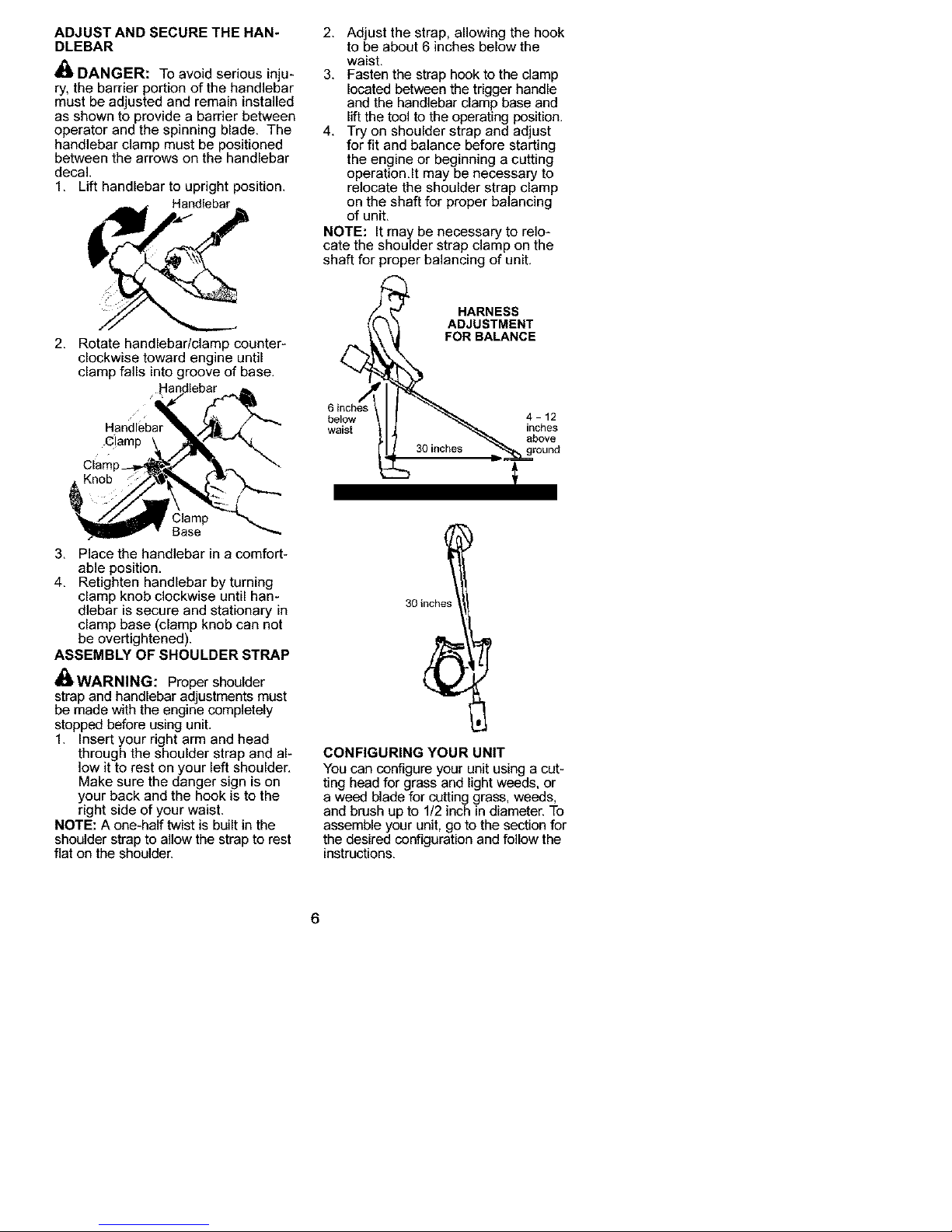
ADJUST AND SECURE THE HAN*
DLEBAR
_1_DANGER: To avoid serious inju-
ry, the barrier portion of the handlebar
must be adjusted and remain installed
as shown to provide a barrier between
operator and the spinning blade. The
handlebar clamp must be positioned
between the arrows on the handlebar
decal.
1. Lift handlebar to upright position.
Handlebar
2. Adjust the strap, allowing the hook
to be about 6 inches below the
waist.
3. Fasten the strap hook to the clamp
located between the trigger handle
and the handlebar clamp base and
lift the tool to the operating position.
4. Try on shoulder strap and adjust
for fit and balance before starting
the engine or beginning a cutting
operation.It may be necessary to
relocate the shoulder strap clamp
on the shaft for proper balancing
of unit.
NOTE: It may be necessary to relo-
cate the shoulder strap clamp on the
shaft for proper balancing of unit.
2. Rotate handlebar/clamp counter-
clockwise toward engine until
clamp falls into groove of base.
Clamp
Base
3. Place the handlebar in a comfort*
able position.
4. Retighten handlebar byturning
clamp knob clockwise until han-
dlebar is secure and stationary in
clamp base (clamp knob can not
be overtightened).
ASSEMBLY OF SHOULDER STRAP
_1_WARNING: Proper shoulder
strap and handlebar ad ustments must
be made w th the eng ne compete y
stopped before using unit.
1. Insert your right arm and head
through the shoulder strap and al-
low it to rest on your left shoulder.
Make sure the danger sign is on
your back and the hook is to the
right side of your waist.
NOTE: A one-half twist is built in the
shoulder strap to allow the strap to rest
flat on the shoulder.
HARNESS
ADJUSTMENT
FOR BALANCE
6 inches
below
waist
4-12
inches
above
30 inches
CONFIGURING YOUR UNIT
You can configure your unit using a cut*
ting head for grass and light weeds, or
a weed blade for cutting grass, weeds,
and brush up to 1/2 inch in diameter. To
assemble your unit, go to the section for
the desired configuration and follow the
instructions.
6
Page 7
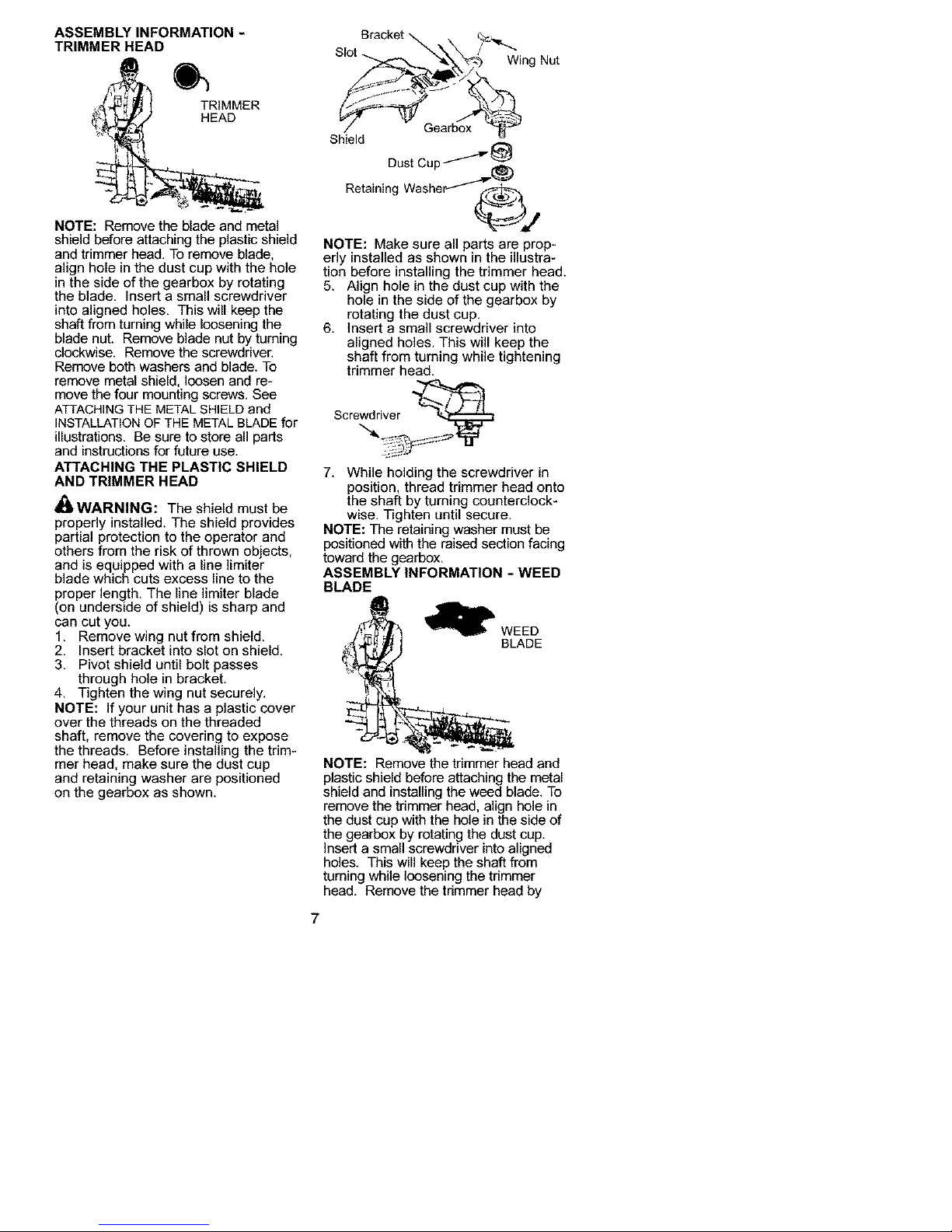
ASSEMBLY INFORMATION -
TRIMMER HEAD
TRIMMER
HEAD
NOTE: Remove the blade and metal
shield before attaching the plastic shield
and trimmer head. To remove blade,
align hole in the dust cup with the hole
in the side of the gearbox by rotating
the blade. Insert a small screwdriver
into aligned holes. This will keep the
shaft from turning while loosening the
blade nut. Remove blade nut by turning
clockwise. Remove the screwdriver.
Remove both washers and blade. To
remove metal shield, loosen and re-
move the four mounting screws. See
ATTACHINGTHE METALSHIELDand
INSTALLATIONOF THE METAL BLADEfor
illustrations. Be sure to store all parts
and instructions for future use.
ATTACHING THE PLASTIC SHIELD
AND TRIMMER HEAD
_WARNING: The shield must be
properly installed. The shield provides
partial protection to the operator and
others from the risk of thrown objects,
and is equipped with a line ]imiter
blade which cuts excess line to the
Droper length. The line limiter blade
on underside of shield) is sharp and
can cut you.
1. Remove wing nut from shield.
2. Insert bracket into slot on shield.
3. Pivot shield until bolt passes
through hole in bracket.
4. Tighten the wing nut securely.
NOTE: If your unit has a plastic cover
over the threads on the threaded
shaft, remove the covering to expose
the threads. Before installing the trim-
mer head, make sure the dust cup
and retaining washer are positioned
on the gearbox as shown.
Bracket Q
Shield
DustCup _" _
Retaining Washer-_
NOTE: Make sure all parts are prop-
erly installed as shown in the illustra-
tion before installing the trimmer head.
5. Align hole in the dust cup with the
hole in the side of the gearbox by
rotating the dust cup,
6. Insert a small screwdriver into
aligned holes. This will keep the
shaft from turning while tightening
trimmer head.
Sore _,
7. While holding the screwdriver in
position, thread trimmer head onto
the shaft by turning counterclock-
wise. Tighten until secure.
NOTE: The retaining washer must be
positioned with the raised section facing
toward the gearbox.
ASSEMBLY INFORMATION - WEED
BLADE
E
NOTE: Remove the trimmer head and
plastic shield before attaching the metal
shield and installing the weed blade. To
remove the trimmer head, align hole in
the dust cup with the hole in the side of
the gearbox by rotating the dust cup.
Insert a small screwdriver into aligned
holes. This will keep the shaft from
turning while loosening the trimmer
head. Remove the trimmer head by
7
Page 8
turning clockwise. Remove the screw-
driver. To remove the plastic shield,
loosen and remove wing nut. Pivot
shield to release bracket from slot. See
INSTALLATIONOF THE CUTTINGHEAD
and ATTACHINGTHE PLASTIC SHIELDfor
illustrations. Be sure to store all parts
and instructions for future use. Never
use the trimmer head with the metal
blade installed.
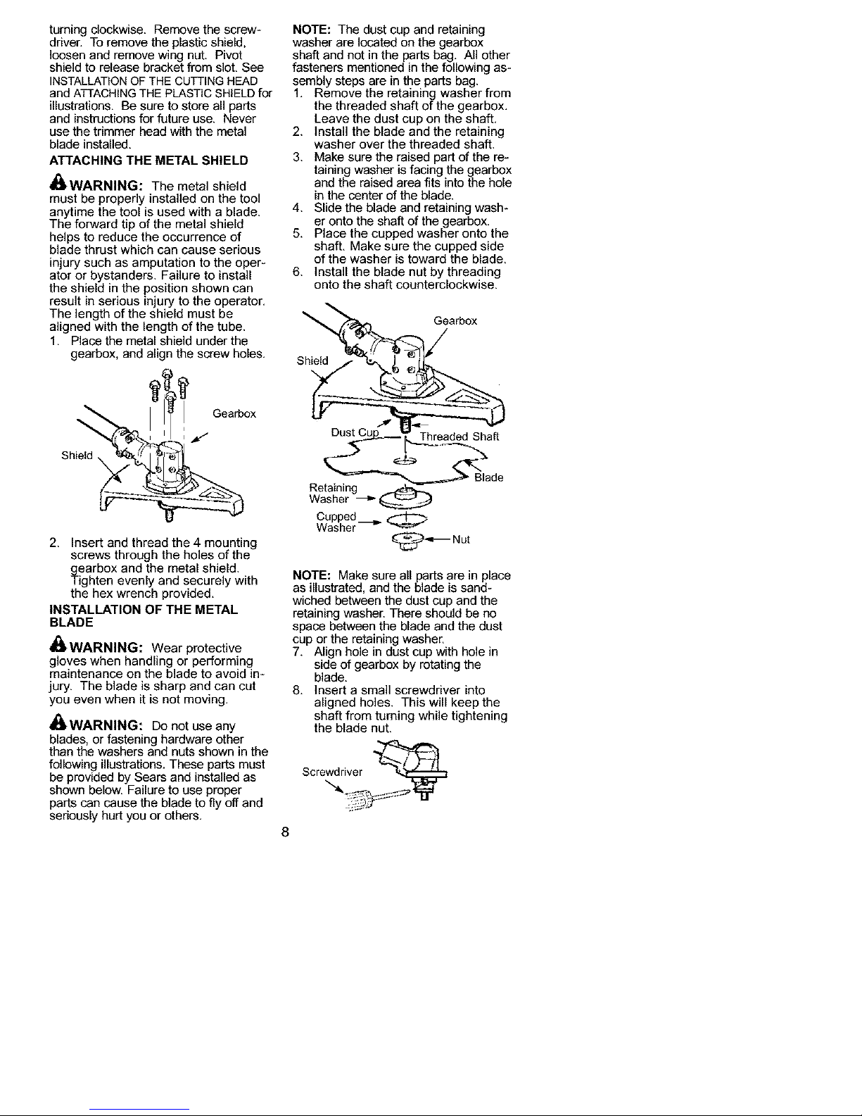
ATTACHING THE METAL SHIELD
_I_i,WARNING: The metal shield
must be properly installed on the tool
anytime the tool is used with a blade.
The forward tip of the metal shield
helps to reduce the occurrence of
blade thrust which can cause serious
injury such as amputation to the oper-
ator or bystanders. Failure to install
the shield in the position shown can
result in serious injury to the operator.
The length of the shield must be
aligned with the length of the tube.
1. Place the metal shield under the
gearbox, and align the screw holes.
If
Gearbox
' _-
Shield
2. Insert and thread the 4 mounting
screws through the holes of the
grearbox and the metal shield.
ighten evenly and securely with
the hex wrench provided.
INSTALLATION OF THE METAL
BLADE
_ WARNING: Wear protective
gloves when handling or performing
maintenance on the blade to avoid in-
jury. The blade is sharp and can cut
you even when it is not moving.
_WARNING: Do not use any
blades, or fastening hardware other
than the washers and nuts shown in the
following illustrations. These parts must
be provided by Sears and installed as
shown below. Failure to use proper
parts can cause the blade to fly off and
seriously hurt you or others.
NOTE: The dust cup and retaining
washer are located on the gearbox
shaft and not in the parts bag. All other
fasteners mentioned in the following as-
sembly steps are in the parts bag.
1. Remove the retaining washer from
the threaded shaft of the gearbox.
Leave the dust cup on the shaft.
2. Install the blade and the retaining
washer over the threaded shaft.
3. Make sure the raised part of the re-
taining washer is facing the gearbox
and the raised area fits into the hole
in the center of the blade.
4. Slide the blade and retaining wash-
er onto the shaft of the gearbox.
5. Place the cupped washer onto the
shaft. Make sure the cupped side
of the washer is toward the blade.
6. Install the blade nut by threading
onto the shaft counterclockwise.
Gearbox
Shield
Threaded Shaft
Retaining
Washer
Cupped
Washer -_
_-_Nut
NOTE: Make sure all parts are in place
as illustrated, and the blade is sand-
wiched between the dust cup and the
retaining washer. There should be no
space between the blade and the dust
cup or the retaining washer.
7. Align hole in dust cup with hole in
side of gearbox by rotating the
blade.
8. insert a small screwdriver into
aligned holes. This will keep the
shaft from turning while tightening
the blade nut.
8
Page 9
9. Tighten blade nut firmly with a
wrench while holding screwdriver
in position.
10. Remove the screwdriver.
11. Turn blade by hand. If the blade
binds against the shield, or appears
to be uneven, the blade is not cen-
tered, and you must reinstall.
NOTE: To remove blade, insert screw-
driver into aligned holes. Unthread the
nut and remove parts. Be sure to store
parts and instructions for future use.
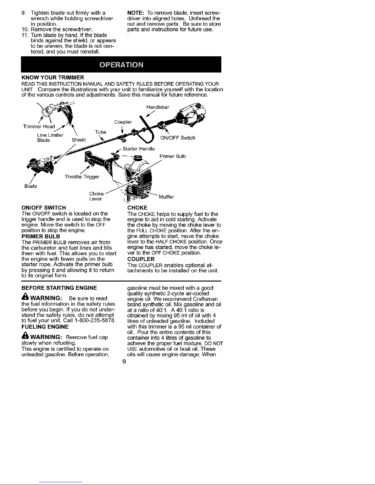
KNOW YOUR TRIMMER
READTHIS INSTRUCTIONMANUALANDSAFETYRULES BEFOREOPERATINGYOUR
UNIT. Compare the illustrations with your unit to familiarize yourself with the location
of the various controls and adjustments. Save this manual for future reference.
_-_ Handlebar
Coupler
Trim
Line Limiter \ Tube
Blade Shield ON/OFF Switch
Primer Bulb
Blade
Lever
ON/OFF SWITCH
The ON/OFF switch is located on the
trigger handle and is used to stop the
engine. Move the switch to the OFF
position to stop the engine.
PRIMER BULB
The PRIMER BULB removes air from
the carburetor and fuel lines and fills
them with fuel. This allows you to start
the engine with fewer pulls on the
starter rope. Activate the primer bulb
by pressing it and allowing it to return
to its original form.
er
CHOKE
The CHOKEhelps to supply fuel to the
engine to aid in cold starting. Activate
the choke by moving the choke lever to
the FULL CHOKE position. After the en-
gine attempts to start, move the choke
lever to the HALF CHOKE position. Once
engine has started, move the choke le-
ver to the OFF CHOKEposition.
COUPLER
The COUPLER enables optional at-
tachments to be installed on the unit.
BEFORE STARTING ENGINE
_1_WARNING: Be sure to read
the fuel information in the safety rules
before you begin, If you do not under-
stand the safety rules, do not attempt
to fuel your unit, Call 1-800-235-5878,
FUELING ENGINE
_WARNING: Remove fuel cap
slowly when refueling,
This engine is certified to operate on
unleaded gasoline, Before operation,
gasoline must be mixed with a good
quality synthetic 2-cycle air-cooled
engine oil. We recommend Craftsman
brand synthetic oil. Mix gasoline and oil
at a ratio of 40:1. A 40:1 ratio is
obtained by mixing 95 ml of oil with 4
litres of unleaded gasoline. Included
with this trimmer is a 95 ml container of
oil. Pour the entire contents of this
container into4 litres of gasoline to
achieve the proper fuel mixture. DO NOT
USEautomotive oil or boat oil. These
oils will cause engine damage. When
9
Page 10
mixingfuel,followinstructionsprintedon
container.
Onceoilisaddedtogasoline,shake
containermomentarilytoassurethatthe
fuelisthoroughlymixed.Alwaysread
andfollowthesafetyrulesrelatingto
fuelbeforefuelingyourunit.
IMPORTANT
Experienceindicatesthatalcohol
blendedfuels(calledgasoholorusing
ethanolormethanol)canattractmois-
turewhichleadstoseparationand
formationofacidsduringstorage.
Acidicgascandamagethefuelsys-
temofanenginewhileinstorage.
Toavoidengineproblems,emptythe
fuelsystembeforestoragefor30days
orlonger.Drainthegastank,startthe
engineandletitrununtilthefuellines
andcarburetorareempty.Usefresh
fuelnextseason.
Neveruseengineorcarburetorclean-
erproductsinthefueltankorperma-
nentdamagemayoccur.
SeetheSTORAGEsectionforaddition-
alinformation.
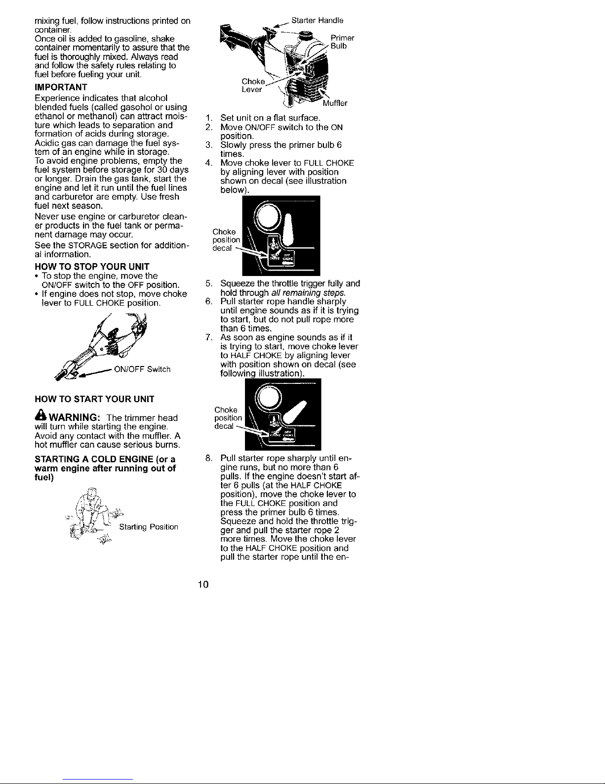
HOW TO STOP YOUR UNIT
• To stop the engine, move the
ONIOFF switch to the OFF position.
• If engine does not stop, move choke
lever to FULL CHOKE position.
;witch
HOW TO START YOUR UNIT
_ WARNING: The trimmer head
will turn while starting the engine.
Avoid any contact with the muffler. A
hot muffler can cause serious burns.
STARTING A COLD ENGINE (or a
warm engine after running out of
fuel)
Starting Position
Starter Handle
Primer
-"Bulb
Choke
Lever
Muffler
1. Set unit on a flat surface.
2. Move ON/OFF switch to the ON
position.
3. Slowly press the primer bulb 6
times.
4. Move choke lever to FULL CHOKE
by aligning lever with position
shown on decal (see illustration
below).
Choke
position
decal
5. Squeeze the throttle trigger fully and
hold through all remaining steps.
6. Pull starter rope handle sharply
until engine sounds as if it is trying
to start, but do not pull rope more
than 6 times.
7. As soon as engine sounds as if it
is trying to start, move choke lever
to HALF CHOKE by aligning lever
with position shown on decal (see
illustration).
Choke
position
8.
Pull starter rope sharply until en-
gine runs, but no more than 6
pulls. If the engine doesn't start af-
ter 6 pulls (at the HALF CHOKE
position), move the choke lever to
the FULL CHOKE position and
press the primer bulb 6 times.
Squeeze and hold the throttle trig-
ger and pull the starter rope 2
more times. Move the choke lever
to the HALF CHOKE position and
pull the starter rope until the en-
10
Page 11
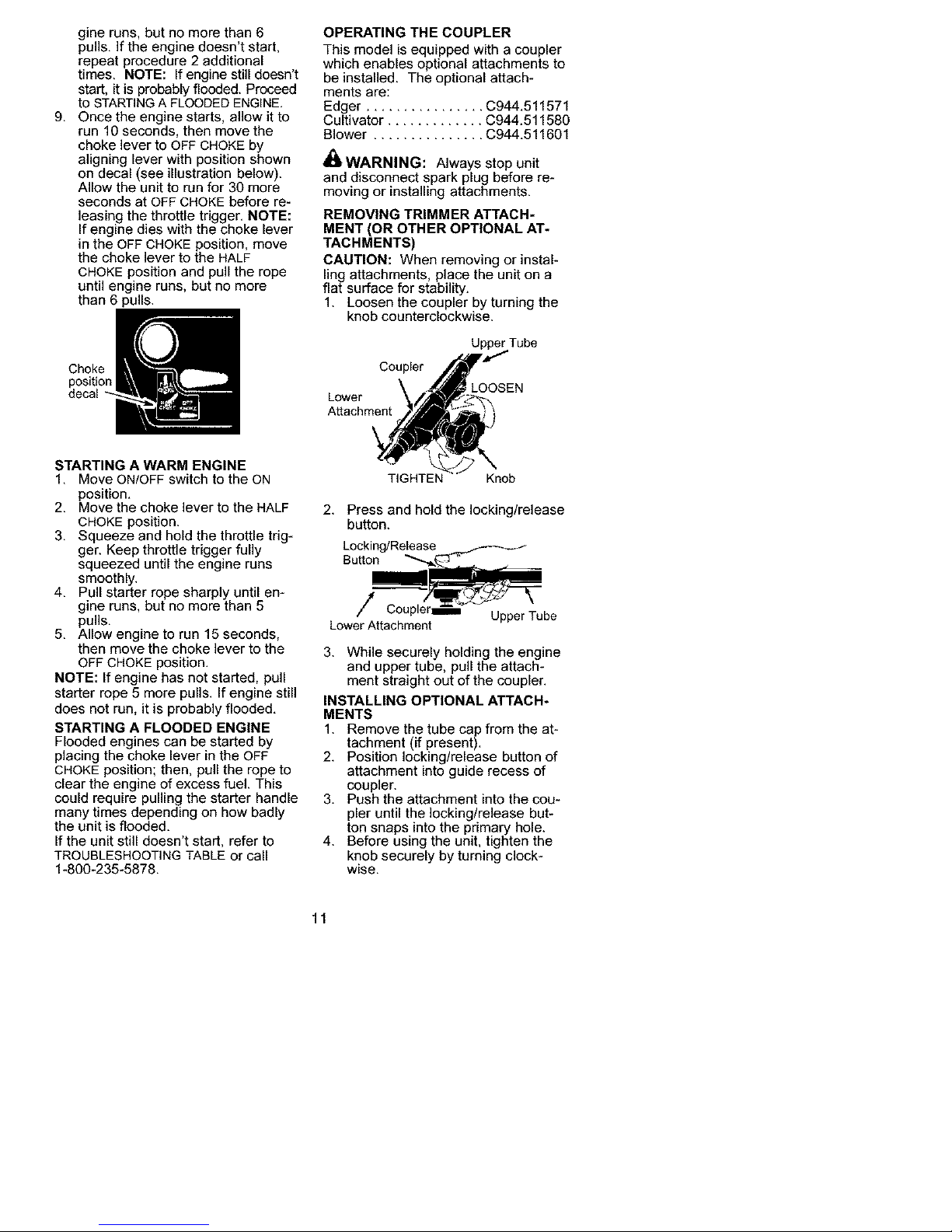
g,
gine runs, but no more than 6
pulls. If the engine doesn't start,
repeat procedure 2 additional
times. NOTE: If engine still doesn't
start, it is probably flooded. Proceed
to STARTINGA FLOODED ENGINE.
Once the engine starts, allow it to
run 10 seconds, then move the
choke lever to OFF CHOKE by
aligning lever with position shown
on decal (see illustration below).
Allow the unit to run for 30 more
seconds at OFF CHOKE before re-
leasing the throttle trigger. NOTE:
If engine dies with the choke lever
in the OFF CHOKE position, move
the choke lever to the HALF
CHOKE position and pull the rope
until engine runs, but no more
than 6 pulls.
Choke
position
OPERATING THE COUPLER
This model is equipped with a coupler
which enables optional attachments to
be installed. The optional attach-
ments are:
Edger ................ C944.511571
Cultivator ............. C944.511580
Blower ............... C944.511601
_I_WARNING: Always stop unit
and disconnect spark plug before re-
moving or installing attachments.
REMOVING TRIMMER ATTACH-
MENT (OR OTHER OPTIONAL AT*
TACHMENTS)
CAUTION: When removing or instal-
ling attachments, place the unit on a
flat surface for stability.
1. Loosen the coupler by turning the
knob counterclockwise.
UpperTube
Coupler
Lower
Attachment
STARTING A WARM ENGINE
1. Move ON/OFF switch to the ON
position.
2. Move the choke lever to the HALF
CHOKE position.
3. Squeeze and hold the throttle trig-
ger. Keep throttle trigger fully
squeezed until the engine runs
smoothly.
4. Pull starter rope sharply until en-
gine runs, but no more than 5
pulls.
5. Allow engine to run 15 seconds,
then move the choke lever to the
OFF CHOKE position.
NOTE: If engine has not started, pull
starter rope 5 more pulls. If engine still
does not run, it is probably flooded.
STARTING A FLOODED ENGINE
Flooded engines can be started by
placing the choke lever in the OFF
CHOKE position; then, pull the rope to
clear the engine of excess fuel. This
could require pulling the starter handle
many times depending on how badly
the unit is flooded.
If the unit still doesn't start, refer to
TROUBLESHOOTING TABLE or call
1-800-235-5878.
TIGHTEN Knob
2. Press and hold the locking/release
button.
Locking/Release
Button
/
LowerAttachment
UpperTube
3. While securely holding the engine
and upper tube, pull the attach-
ment straight out of the coupler.
INSTALLING OPTIONAL ATTACH-
MENTS
1. Remove the tube cap from the at-
tachment (if present).
2. Position locking/release button of
attachment into guide recess of
coupler.
3. Push the attachment into the cou-
pler until the locking/release but-
ton snaps into the primary hole.
4. Before using the unit, tighten the
knob securely by turning clock-
wise.
11
Page 12
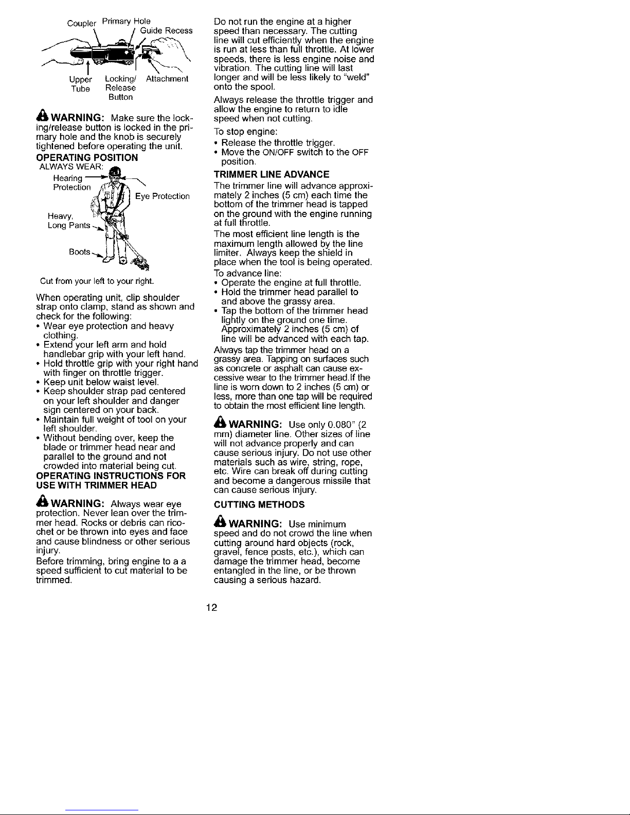
Coupler Primary Hole
Upper Locking/ Attachment
Tube Release
Button
_1_WARNING: Make sure the lock-
ing/release button is locked in the pri-
mary hole and the knob is securely
tightened before operating the unit.
OPERATING POSITION
ALWAYSWEAR: _1
Hearing -_P',_'L,r_-,_
Protection __
,_ _ Eye Protection
Heavy, :_[ _'/
Long Pants _
Boots-.._ _ _ _
Cut from your left to your right.
When operating unit, clip shoulder
strap onto clamp, stand as shown and
check for the following:
• Wear eye protection and heavy
clothing.
• Extend your left arm and hold
handlebar grip with your left hand.
• Hold throttle grip with your right hand
with finger on throttle trigger.
• Keep unit below waist level.
• Keep shoulder strap pad centered
on your left shoulder and danger
sign centered on your back.
• Maintain full weight of tool on your
left shoulder.
• Without bending over, keep the
blade or trimmer head near and
parallel to the ground and not
crowded into material being cut.
OPERATING INSTRUCTIONS FOR
USE WITH TRIMMER HEAD
DWARNING: Always wear eye
protection. Never lean over the trim-
mer head. Rocks or debris can rico-
chet or be thrown into eyes and face
and cause blindness or other serious
injury.
Before trimming, bring engine to a a
speed sufficient to cut material to be
trimmed.
Do not run the engine at a higher
speed than necessary. The cutting
line will cut efficiently when the engine
is run at less than full throttle. At lower
speeds, there is less engine noise and
vibration. The cutting line will last
longer and will be less likely to "weld"
onto the spool.
Always release the throttle trigger and
allow the engine to return to idle
speed when not cutting.
To stop engine:
• Release the throttle trigger.
• Move the ON/OFF switch to the OFF
position.
TRIMMER LINE ADVANCE
The trimmer line will advance approxi-
mately 2 inches (5 cm) each time the
bottom of the trimmer head is tapped
on the ground with the engine running
at full throttle.
The most efficient line length is the
maximum length allowed by the line
limiter. Always keep the shield in
place when the tool is being operated.
To advance line:
• Operate the engine at full throttle.
• Hold the trimmer head parallel to
and above the grassy area.
• Tap the bottom of the trimmer head
lightly on the ground one time.
Approximately 2 inches (5 cm) of
line will be advanced with each tap.
Always tap the trimmer head on a
grassy area. Tapping on surfaces such
as concrete or asphalt can cause ex-
cessive wear to the trimmer head.If the
line is worn down to 2 inches (5 cm) or
less, more than one tap will be required
to obtain the most efficient line length.
_WARNING: Use only 0.080" (2
ram) diameter line. Other sizes of line
will not advance properly and can
cause serious injury. Do not use other
materials such as wire, string, rope,
etc. Wire can break off during cutting
and become a dangerous missile that
can cause senous =njury.
CUTTING METHODS
_I_WARNING: Use minimum
speed and do not crowd the line when
cutting around hard objects (rock,
gravel, fence posts, etc.), which can
damage the trimmer head, become
entangled in the line, or be thrown
causing a serious hazard.
12
Page 13
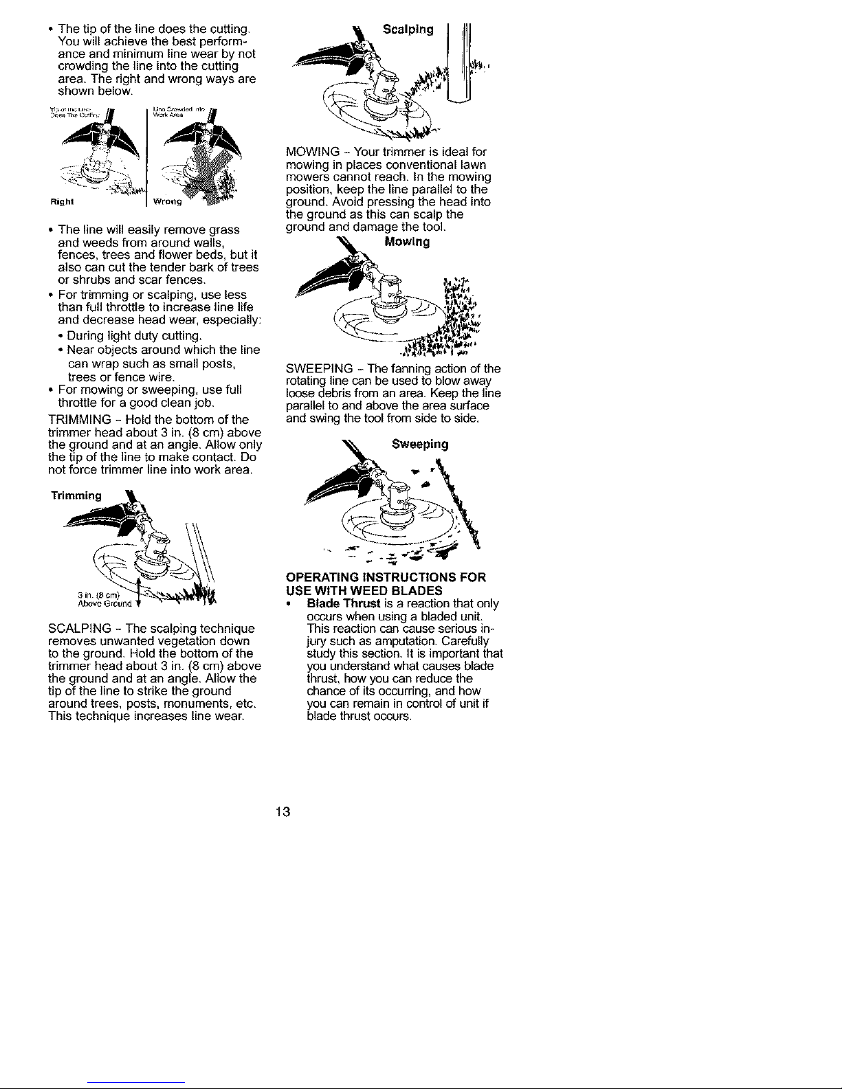
• The tip of the line does the cutting.
You will achieve the best perform-
ance and minimum line wear by not
crowding the line into the cutting
area. The right and wrong ways are
shown below.
Right
• The line will easily remove grass
and weeds from around walls,
fences, trees and flower beds, but it
also can cut the tender bark of trees
or shrubs and scar fences.
• For trimming or scalping, use less
than full throttle to increase line life
and decrease head wear, especially:
• During light duty cutting.
• Near objects around which the line
can wrap such as small posts,
trees or fence wire.
• For mowing or sweeping, use full
throttle for a good clean job.
TRIMMING - Hold the bottom of the
trimmer head about 3 in. (8 cm) above
the ground and at an angle. Allow only
the tip of the line to make contact. Do
not force trimmer line into work area.
Trimming
SCALPING - The scalping technique
removes unwanted vegetation down
to the ground. Hold the bottom of the
trimmer head about 3 in. (8 cm) above
the ground and at an angle. Allow the
tip of the line to strike the ground
around trees, posts, monuments, etc.
This technique increases line wear.
Scalping
MOWING - Your trimmer is ideal for
mowing in places conventional lawn
mowers cannot reach. In the mowing
position, keep the line parallel to the
ground. Avoid pressing the head into
the ground as this can scalp the
ground and damage the tool.
Mowing
SWEEPING - The fanning action of the
rotating line can be used to blow away
loose debris from an area. Keep the line
parallel to and above the area surface
and swing the tool from side to side.
"_ Sweeping
_'8 r
OPERATING INSTRUCTIONS FOR
USE WITH WEED BLADES
Blade Thrust is a reaction that only
occurs when using a bladed unit.
This reaction can cause serious in-
jury such as amputation. Carefully
study this section. It is important that
you understand what causes blade
thrust, how you can reduce the
chance of its occurring, and how
you can remain in control of unitif
blade thrustoccurs.
13
Page 14
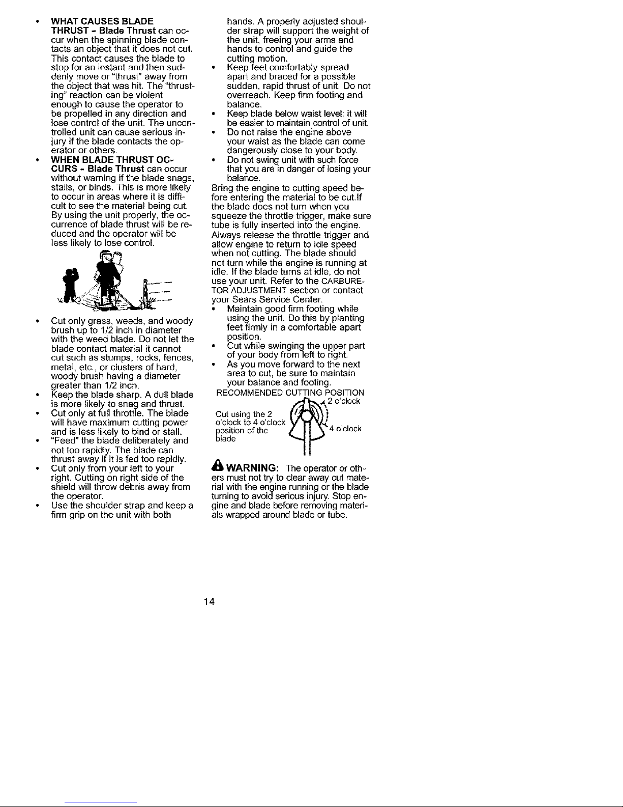
WHAT CAUSES BLADE
THRUST - Blade Thrust can oc-
cur when the spinning blade con-
tacts an object that it does not cut.
This contact causes the blade to
stop for an instant and then sud-
denly move or "thrust" away from
the object that was hit. The "thrust-
ing" reaction can be violent
enough to cause the operator to
be propelled in any direction and
lose control of the unit. The uncon-
trolled unit can cause serious in-
jury if the blade contacts the op-
erator or others.
WHEN BLADE THRUST OC-
CURS - Blade Thrust can occur
without warning if the blade snags,
stalls, or binds. This is more likely
to occur in areas where it is diffi-
cult to see the material being cut.
By using the unit properly, the oc-
currence of blade thrust will be re-
duced and the operator will be
less likely to lose control.
Cut only grass, weeds, and woody
brush up to 1/2 inch in diameter
with the weed blade. Do not let the
blade contact material it cannot
cut such as stumps, rocks, fences,
metal, etc., or clusters of hard,
woody brush having a diameter
greater than 1/2 inch.
Keep the blade sharp. A dull blade
is more likely to snag and thrust.
Cut only at full throttle. The blade
will have maximum cutting power
and is less likely to bind or stall.
Feed the blade deliberately and
not too rapidly. The blade can
thrust away if it is fed too rapidly.
Cut only from your left to your
right. Cutting on right side of the
shield will throw debris away from
the operator.
Use the shoulder strap and keep a
firm grip on the unit with both
hands. A properly adjusted shoul-
der strap will support the weight of
the unit, freeing your arms and
hands to control and guide the
cutting motion.
Keep feet comfortably spread
apart and braced for a possible
sudden, rapid thrust of unit. Do not
overreach. Keep firm footing and
balance.
Keep blade below waist level; it will
be easier to maintain control of unit.
Do not raise the engine above
your waist as the blade can come
dangerously close to your body.
Do not swing unit with such force
that you are in danger of losing your
balance.
Bring the engine to cutting speed be-
fore entering the material to be cut.if
the blade does not turn when you
squeeze the throttle trigger, make sure
tube is fully inserted into the engine.
Always release the throttle trigger and
allow engine to return to idle speed
when not cutting. The blade should
not turn while the engine is running at
idle. If the blade turns at idle, do not
use your unit. Refer to the CARBURE-
TOR ADJUSTMENT section or contact
your Sears Service Center.
Maintain good firm footing while
using the unit. Do this by planting
feet firmly in a comfortable apart
position.
Cut while swinging the upper part
of your body from left to right.
As you move forward to the next
area to cut, be sure to maintain
your balance and footing.
RECOMMENDED CUTTING POSITION
_ o'clock
Cut using the 2 _;
o'clock to 4 o'clock
position of the 4 o'clock
blade
_I_t,WARNING: The operator or oth-
ers must not try to clear away cut mate-
rial with the engine running or the blade
turning to avoid serious injury. Stop en-
gine and blade before removing materi-
als wrapped around blade or tube.
14
Page 15

_1_WARNING: For each optional
attachment used. read entire instruc-
tion manual before use and follow all
warnings and instructions in manual
and on attachment.
_WARNING: Ensure handlebar
remains installed on upper tube (en-
gine end of unit) at all times.
t Handlebar
EDGER SAFETY
_WARNING: Inspect the area to
be edged before each use. Remove
objects (rocks, broken glass, nails,
wire, etc.) which can be thrown by the
blade or can wrap around the shaft.
• Blade rotates momentarily after the
trigger is released. The blade can
seriously cut you or others.
• Allow blade to stop before removing
it from the cut.
Bladerotatas Allow bladetostop
deforeramovingit
afterthe fromthe cut.
• Throw away blades that are bent,
warped, cracked, broken or dam-
aged in any other way. Replace
parts that are cracked, chipped, or
damaged before using the unit.
• Do not attempt to remove cut material
nor hold material to be cut when the
engine is running or when cutting
blade is moving.
• Always keep the wheel and depth ad-
justing skid in contact with the ground.
• Always push the unit slowly over the
ground. Stay alert for uneven side-
walks, holes in the terrain, large
roots, etc.
• Always use the handlebar when us-
ing edger attachment.
BLOWER/VACUUM SAFETY
_I_WARNING: Inspect area before
starting unit. Remove all debris and
hard objects such as rocks, glass,
wire, etc. that can ricochet, be thrown,
or otherwise cause injury or damage
during operation.
• Do not set unit on any surface except
a clean, hard area while engine is
running. Debris such as gravel, sand,
dust, grass, etc., could be picked up
by the air intake and thrown out
through discharge opening, damaging
unit, property, or causing serious injury
to bystanders or operator.
• Never place objects inside the blow-
er tubes, vacuum tubes or blower
outlet. Always direct the blowing de-
bris away from people, animals,
glass, and solid objects such as
trees, automobiles, walls, etc. The
force of air can cause rocks, dirt, or
sticks to be thrown or to ricochet
which can hurt people or animals,
break glass, or cause other damage.
• Never run unit without the proper
equipment attached. When using
your unit as a blower, always install
blower tubes.
• Check air intake opening, blower
tubes or vacuum tubes frequently,
always with engine stopped and
spark plug disconnected. Keep
vents and discharge tubes free of
debris which can accumulate and
restrict proper air flow.
• Never place any object in air intake
opening as this could restrict proper
air flow and cause damage to the unit.
• Never use for spreading chemicals,
fertilizers, or other substances which
may contain toxic materials.To avoid
spreading fire, do not use near leaf or
brush fires, fireplaces, barbecue pits,
ashtrays, etc.
CULTIVATOR SAFETY
_WARNING: Rotating tines can
cause serious injury. Keep away from
rotating tines. Stop the engine and
disconnect the spark plug before un-
clogging tines or making repairs.
15
Page 16

4_WARNING: Inspect the area to
be cultivated before starting the unit.
Remove all debris and hard and sharp
objects such as rocks, vines, branch-
es, rope, string, etc.
• Avoid heavy contact with solid objects
that might stop the tines. If heavy
contact occurs, stop the engine and
inspect the unit for damage.
• Never operate the cultivator without
the tine cover in place and properly
secured.
• Keep the tines and guard clear of
debris.
• After striking a foreign object, stop
the engine, disconnect the spark
plug and inspect the cultivator for
damage. Repair before restarting.
• Disconnect attachment from the drive
engine before cleaning the tines with
a hose and water to remove any
build-up. Oil the tines to prevent rust.
• Always wear gloves when servicing
or cleaning the tines. The tines be-
come very sharp from use.
• Do not run unit at high speed unless
cultivating.
HEDGE TRIMMER SAFETY
,,&
_1_DANGER: RISK OF CUT; KEEP
HANDS AWAY FROM BLADE - Blade
moves momentarily after the trigger is
released. Do not attempt to clear away
cut material when the blade is in mo-
tion. Make sure the switch is in the OFF
position, the spark plugwire is diScon-
nected, and the bladehas stopped
moving before removing ammed mate-
rial from the cutting blade. Do not grab
or hold the unit by the cutting blade.
Blades move Allow blades to stop
momentarily before removing
after the them from the cut.
t ggeria
_ released, /" ._
_l_ WARNING: Inspect the area be-
fore starting the unit. Remove all de-
bris and hard objects such as rocks,
glass, wire, etc. that can ricochet, be
thrown, or otherwise cause injury or
damage during operation.
• Do not use a cutting blade that is
bent, warped, cracked, broken or
damaged in any other way. Have
worn or damaged parts replaced by
your Sears Service Center.
• Always keep unit in front of your
body. Keep all parts ofyour body
away from the cutting blade.
• Keep the cutting blade and air vents
clear of debris.
POLE PRUNER SAFETY
_I_WARNING: The reciprocating
blade/rotating chain can cause severe
injury. Inspect the unit before use. Do
not operate unit with a bent, cracked
or dull blade or dull chain. Keep away
from the blade/chain.
_I_WARNING: The reciprocating
blade/rotating chain is sharp. Do not
touch. To prevent serious injury, al-
ways stop engine and ensure blade/
chain has stopped moving, disconnect
spark plug, and wear gloves when
changing or handling the blade or
chain.
_I_WARNING: Acoasting blade/
rotating chain can cause injury while it
continues to move after the engine is
stopped. Maintain proper control of
the unit until the blade/chain has com-
Fletely stopped moving. Keep hands,
ace and feet at a distance from all
moving parts. Do not attempt to touch
or stop the blade or chain when it is
moving.
4_WARNING: Falling objects can
cause severe head injury. Wear head
protection when operating this unit
with a pole pruner attachment.
16
Page 17

_ WARNING: To prevent serious
injury, do not use more than one boom
extension with a pole pruner attach-
ment.
_ WARNING: Keep the pruner
away from power lines or electrical
wires.
• Onty use for pruning _imbs or
branches up to 4 inches in diameter.
• Do not operate the unit faster than
the speed needed to prune. Do not
run the unit at high speed when not
pruning.
• Always stop the unit when work is
delayed or when walking from one
cutting location to another.
• if you strike or become entangled
with a foreign object, stop the engine
immediately and check for damage.
Have any damage repaired by a
Sears Service Center before at-
tempting further operations. Discard
blades that are bent, warped,
cracked or broken.
• Stop the unit immediately if you feel
excessive vibration. Vibration is a
sign of trouble. Inspect thoroughly
for loose nuts, bolts or damage be-
fore continuing. Contact Sears Ser-
vice for repair or replacement of af-
fected parts as necessary.
SNOW THROWER SAFETY
_WARNING: Keep hands and
feet away from the rotor when starting
or running the engine. Never attempt
to clear the rotor with the engine/motor
running. Stop engine and disconnect
spark plug before unclogging snow or
debris from discharge chute or when
adjusting vanes.
_WARNING: Never lean over dis-
charge chute. Rocks or debris could
be thrown into the eyes and face and
cause serious injury or blindness.
_WARNING: Inspect the area
where the unit is to be used. Remove
objects that could be thrown or dam-
age the unit. Some objects may be
hidden b}( fallen snow - be alert for
the possibility.
• Direct material discharge away from
glass enclosureS, automobiles, etc.
• Do not run engine at high speed
while not removing snow.
• Be attentive when using the snow-
thrower, and stay alert for holes in the
terrain and other hidden hazards.
• Make sure the rotor will spin freely
before attaching the snowthrower to
the powerhead.
• If the rotor will not rotate freely due
to frozen ice, thaw the unit before
thoroughly before attempting to op-
erate under power.
• Keep the rotor clear of debris.
• Do not throw snow near other
people. The snow thrower could
propel small objects at high speed
causing injury.
• After striking a foreign object, stop
the engine, disconnect spark plug
and inspect the snowthrower for
damage and repair if necessary be-
fore restarting unit.
• Never operate the snowthrower near
glass enclosures, automobiles and
trucks.
• Never attempt to use the snow-
thrower on a roof.
• Never operate the snowthrower near
window wells, dropoffs, etc.
• Never discharge snow onto public
roads or near moving traffic.
• Clear snow from slopes by going up
and down; never across. Use cau-
tion when changing directions. Nev-
er clear snow from steep slopes.
• Let snowthrower run for a few min-
utes after clearing snow so moving
parts do not freeze.
• Look behind and use care when
backing up. Exercise caution to
avoid slipping or falling, especially
when operating in reverse.
• Know how to stop quickly,
17
Page 18

MAINTENANCE SCHEDULE
WARNING: Disconnect the spark plug before performing maintenance
except for carburetor adjustments.
CARE & MAINTENANCE TASK WHEN TO PERFORM
Check for loose fasteners and parts Before each use
Check for damaged or worn parts Before each use
Inspect and clean unit and labels After each use
Clean air filter Every 5 hours of operation
Replace spark plug Yearly
_ENERAL RECOMMENDATIONS
The warranty on this unit does not
cover items that have been sub ected
to operator abuse or neg gence. To
receive full value from the warranty,
the operator must maintain unit as
instructed in this manual. Various ad-
justments will need to be made peri-
odically to properly maintain your unit.
CHECK FOR LOOSE
:LEAN AIR FILTER
A dirty air filter decreases engine per-
formance and increases fuel con-
sumption and harmful emissions. Al-
ways clean after every 5 hours of
operation.
1. Clean the cover and the area
around it to keep dirt from falling
into the carburetor chamber when
the cover is removed.
FASTENERS AND PARTS
• Spark Plug Boot
• Air Filter
Housing Screws
o
• Assist Handle Screw
• Debris Shield
CHECK FOR DAMAGED OR
WORN PARTS
2. Remove parts by pressing button
to release air filter cover.
NOTE: To avoid creating a fire hazard
or producing harmful evaporative
emissions, do not clean filter in gaso-
line or other flammable solvent.
3. Wash the filter in soap and water.
4. Allow filter to dry.
5. Add a few drops of oil to the filter;
Contact Sears Service Center for re-
placement of damaged or worn parts.
• ON/OFF Switch - Ensure ON/OFF
switch functions properly by moving
the switch to the OFF position. Make
sure engine stops; then restart en-
gine and continue.
• Fuel Tank - Discontinue use of unit
if fuel tank shows signs of damage
or leaks.
• Debris Shield - Discontinue use of
unit if debris shield is damaged.
INSPECT AND CLEAN UNIT AND LA-
BELS
• After each use, inspect complete
unit for loose or damaged parts.
Clean the unit and labels using a
damp cloth with a mild detergent.
• Wipe off unit with a clean dry cloth.
squeeze the filter to distribute oil.
6. Replace parts.
• Air Filter
Button ¢_ _ ._:,
_;_'_ . " Air Filter
. Cover
REPLACE SPARK PLUG
Replace the spark plug each year to
ensure the engine starts easier and
runs better. Set spark plug gap at
0.025 inch. Ignition timing is fixed and
nonadjustable.
1. Twist, then pull off spark plug boot.
2. Remove spark plug from cylinder
and discard.
3. Replace with Champion RCJ-6Y
spark plug and tighten securely
with a 3/4 inch socket wrench.
4. Reinstall the spark plug boot.
18
Page 19

REPLACING THE LINE
1. Move ON/OFF switch to the ON
position.
2. Disconnect the spark plug wire.
3. Remove spool by firmly pulling on
tap button.
4. Clean entire surface of hub and
spool.
5. Replace with a pre-wound spool, or
cut two lengths of 12-1/2 feet of
0.080" (2 mm) diameter
Craftsman® brand line.
I_ WARNING: Never use wire,
rope, string, etc., which can break off
and become a dangerous missile.
6. Insert ends of the lines about 1/2
inch (1 cm) into the small holes on
the inside of spool.
U" Ji>_ No es
V, t! _<:P_I
J 'J' l
Line exit holes Line in Notch
\
Line in Notch
7. Wind the line evenly and tightly
onto the spool. Wind in the direc-
tion of the arrows found on the
spool.
8. Push the lines into the notches,
leaving 3 to 5 inches (7 - 12 cm)
unwound.
9. insert the lines into the the exit
holes in the hub as shown in the
illustration.
10. Align the notches with the line exit
holes.
11. Push spool into hub until it snaps
into place.
12. Pull the lines extending outside of
the hub to release the lines from
the notches.
BLADE REPLACEMENT
Refer to the ASSEMBLY section for
blade replacement instructions and
illustrations.
CARBURETOR ADJUSTMENT
I_ WARNING: Keep others away
when making idle speed adjustments.
The trimmer head, blade or any op-
tional attachment will be spinning dur-
ing most of this procedure. Wear your
protective equipment and observe all
safety precautions. After making ad-
justments, the trimmer head, blade or
any optional attachment must not
move/spin at idle speed.
The carburetor has been carefully set
at the factory. Adjustments may be
necessary if you notice any of the fol-
lowing conditions:
• Engine will net idle when the throttle is
released.
• The trimmer head, blade or optional
attachment moves/spins at idle.
Make adjustments with the unit sup-
ported so the cutting attachment is off
the ground and will not make contact
with any object. Hold the unit by hand
while running and making adjust-
ments. Keep all parts of your body
away from the cutting attachment and
muffler.
Idle Speed Adjustment
Allow engine to idle. Ad ust speed until
engine runs without trimmer head,
blade or optional attachment moving
or spinning (idle too fast) or stalling
(idle speed too slow).
• Turn idle speed screw clockwise to
increase enqine speed if engine
stalls or dies.
• Turn idle speed screw
counterclockwise to decrease
engine speed if trimmer head, blade
or optional attachment moves or
spins at idle.
_ WARNING: Recheck the idle
speed after each adjustment. The
trimmer head, blade or optional at-
tachment must not move or spin at
idle speed to avoid serious injury to
the operator or others.
19
Page 20

Air Filtere___ "
Cover
Idle Spe
Screw
If you require further assistance or are
unsure about performing this proce-
dure, contact your Sears Service Cen-
ter or call our customer assistance
help line at 1-800-235-5878.
_ WARNING: Perform the follow-
ing steps after each use:
• Allow engine to cool before storing
or transporting.
• Store unit and fuel in a well venti-
lated area where fuel vapors cannot
reach sparks or open flames from
water heaters, electric motors or
switches, furnaces, etc.
• Store unit with all guards in place.
Position unit so that any sharp ob-
ect cannot accidentally cause injury.
• Store un t and fue we out of the
reach of children.
SEASONAL STORAGE
Prepare unit for storage at end of sea-
son or if it will not be used for 30 days
or more.
If your unit is to be stored for a period
of time:
• Clean the entire unit before lengthy
storage.
Store in a clean dry area.
Lightly oil external metal surfaces.
FUEL SYSTEM
Under FUELING ENGINE in the OPERA-
TION section of this manual, see mes-
sage labeled IMPORTANT regarding
the use of gasohol in your engine.
Fuel stabilizer is an acceptable alter-
native in minimizing the formation of
fuel gum deposits during storage. Add
stabilizer to the gasoline in the fuel
tank or fuel storage container. Follow
the mix instructions found on stabilizer
container. Run engine at least 5 min-
utes after adding stabilizer.
Craftsman 40:1, 2-cycle engine oil (air
cooled) is already blended with fuel
stabilizer. ]f you do not use this Sears
oil, you can add a fuel stabilizer to
your fuel tank.
ENGINE
• Remove spark plug and pour 1 tea-
spoon of 40:1, 2-cycle engine oil (air
cooled) through the spark plug
opening. Slowly pull the starter rope
8 to 10 times to distribute oil.
• Replace spark plug with new one of
recommended type and heat range.
• Clean air filter.
• Check entire unit for loose screws,
nuts, and bolts. Replace any dam-
aged, broken, or worn parts.
• At the beginning of the next season,
use only fresh fuel having the proper
gasoline to oil ratio.
OTHER
• Do not store gasoline from one sea-
son to another.
• Replace your gasoline can if it starts
to rust.
20
Page 21

TROUBLESHOOTING TABLE
WARNING: Always stop unit and disconnect spark plug before perform-
ing all of the recommended remedies below except remedies that require
operation of the unit.
TROUBLE
Engine will not
start.
Engine will
not idle
properly.
Engine will not
accelerate,
Jacks power,
or dies under
a load.
Engine
smokes
_=xcessively.
Engine runs
hot.
CAUSE
1. ON/OFF switch in
OFF position.
2. Engine flooded.
3. Fuel tank empty.
4. Spark plug not firing.
5. Fuel not reaching
carburetor,
6. Carburetor requires
adjustment.
1. Carburetor requires
adjustment.
2. Crankshaft seals worn.
3. Compression low.
1. Air filter dirty.
2. Spark plug fouled,
3. Carburetor requires
adjustment.
4. Carbon build-up on
muffler outlet screen.
5. Compression low.
1. Choke partially on.
2. Fuel mixture incorrect.
3. Air filter dirty.
4. Carburetor requires
adjustment.
1, Fuel mixture incorrect.
2, Spark plug incorrect,
3, Carburetor requires
adjustment.
4. Carbon build-up on
muffler outlet screen.
REMEDY
1, Move ON/OFF switch to ON.
2, See "Starting a Flooded Engine" in
Operation Section.
3, Fill tank with correct fuel mixture.
4, install new spark plug.
5, Check for dirty fuel filter; replace.
Check for kinked or split fuel line;
repair or replace.
6, Contact Sears Service (see back cover).
1, See "Carburetor Adjustment" in
Service and Adjustments Section.
2, Contact Sears Service (see back cover).
3, Contact Sears Service (see back cover).
1. Clean or replace air filter.
2. Clean or replace plug
and regap,
3. Contact Sears Service (see back cover)
4. Contact Sears Service (see back cover)
5. Contact Sears Service (see back cover)
1. Adjust choke.
2. Empty fuel tank and refill with
correct fuel mixture.
3. Clean or replace air filter.
4. Contact Sears Service (see back cover)
1. See "Fueling Engine" in Operation
section.
2. Replace with correct spark plug.
3. Contact Sears Service (see back cover)
4. Contact Sears Service (see back cover)
21
Page 22

YOUR WARRANTY RIGHTS AND
OBLIGATIONS: The U. S. Environ-
mental Protection Agency/Environ-
ment Canada and Sears Canada.
Inc., are pleased to explain the emis-
sions control system warranty on your
year 2002-2004 small off-road engine.
Sears Canada must warrant the emis-
sion control system on your small off-
road engine for the periods of time listed
below provided there has been no
abuse, neglect, or improper mainte-
nance of your small off-road engine.
Your emission control system includes
parts such as the carburetor and the
ignition system. Where a warrantable
condition exists. Sears Canada will re-
pair your small off-road engine at no
cost to you. Expenses covered under
warranty include diagnosis, parts and
labor. MANUFACTURER S WARRAN-
TY COVERAGE: If any emissions re-
lated part on your engine (as listed un-
der Emissions Control Warranty Parts
List) is defective or a defect in the mate-
rials or workmanship of the engine
causes the failure of such an emission
related part, the part will be repaired or
replaced by Sears Canada. OWNER'S
WARRANTY RESPONSIBILITIES: As
the small off-road engine owner, you
are responsible for the performance of
the required maintenance listed in your
instruction manual. Sears Canada rec-
ommends that you retain all receipts
covering maintenance on your small
off-road engine, but Sears Canada
cannot deny warranty solely for the lack
of receipts or for your failure to ensure
the performance of all scheduled main-
tenance. As the small off-road engine
owner, you should be aware that Sears
Canada may deny you warranty cover-
age if your small off-road engine or a
part of it has failed due to abuse, ne-
glect, improper maintenance, unap-
proved modifications, or the use of parts
not made or approved by the original
equipment manufacturer. You are re-
sponsible for presenting your small off-
road engine to a Sears Canada autho-
rized repair center as soon as a
problem exists. Warranty repairs should
be completed in a reasonable amount
of time, not to exceed 30 days. If you
have any questions regarding your war-
ranty rights and responsibilities, you
should contact your nearest authorized
service center or call Sears Canada at
1-800-665-4455. WARRANTY COM-
MENCEMENT DATE: The warranty pe-
riod begins on the date the small off-
road engine is purchased. LENGTH
OF COVERAGE: This warranty shall be
for a period of two years from the initial
date of purchase. WHAT IS COV-
ERED: REPAIR OR REPLACEMENT
OF PARTS. Repair or replacement of
any warranted part will be performed at
no charge to the owner at an approved
Sears Canada servicing center. If you
have any questions regarding your war-
rarity rights and responsibilities, you
should contact your nearest authorized
service center or call Sears Canada at
1-800-665-4455. WARRANTY PE-
RIOD: Any warranted part which is not
scheduled for replacement as required
maintenance, or which is scheduled
only for regular inspection to the effect
of "repair or replace as necessary" shall
be warranted for 2 years. Any war-
ranted part which is scheduled for re-
placement as required maintenance
shall be warranted for the period of time
up to the first scheduled replacement
point for that part. DIAGNOSIS: The
owner shall not be charged for diagnos-
tic labor which leads to the determina-
tion that a warranted part is defective if
the diagnostic work is performed at an
approved Sears Canada servicing cen-
ter. CONSEQUENTIAL DAMAGES:
Sears Canada may be liable for dam-
ages to other engine components
caused by the failure of a warranted
part still under warranty. WHAT IS NOT
COVERED: All failures caused by
abuse, neglect, or improper mainte-
nance are not covered. ADD-ON OR
MODIFIED PARTS: The use of add-on
or modified parts can be grounds for
disallowing a warranty claim. Sears
Canada is not liable to cover failures of
warranted parts caused by the use of
add-on or modified parts. HOW TO
FILE A CLAIM: If you have any ques-
tions regarding your warranty rights and
responsibilities, you should contact your
nearest authorized service center or call
Sears Canada at 1-800-665-4455.
WHERE TO GET WARRANTY SER-
VICE: Warranty services or repairs shall
be provided at all Sears Canada service
centers. Call 1-800-665-4455. MAIN-
TENANCE, REPLACEMENT AND RE-
PAIR OF EMISSION RELATED
PARTS: Any Sears Canada approved
22
Page 23

replacementpartusedin the pertor-
mance of any warranty maintenance or
repair on emission related parts will be
provided without charge to the owner if
the part is under warranty. EMISSION
CONTROL WARRANTY PARTS LIST:
Carburetor, 19nition System: Spark Plu9
(covered up to maintenance schedule),
Ignition Module. MAINTENANCE
STATEMENT: The owner is responsible
for the performance of all required main-
tenance as defined in the instruction
manual.
The information on the product label indicates which standard your engine is certified.
Example: (Year) EPA Phase 1 or Phase 2 and/or CALIFORNIA,
This engine is certified to be emissions compliant for the following use:
[] Moderate (50 hours)
[] Intermediate (125 hours)
[] Extended (300 hours)
23
Page 24

Garantie 26
R_gles de S6curit6 26
Montage 30
Fonctionnement 34
Entretien 44
R6parations et R6glages 45
Rangement 47
Tableau de D6pannage 48
Garantie de lutte an missions 49
Commande de pieces Page arri_re
GARANTIE LIMITEE DE DEUX (2) ANS SUR LE WEEDWACKER CRAFTSMAN
.,&.ESSENCE
Durante une p6riode de deux (2) an _ compter de la date d'achat, Sears Canada
Inc., _ sa discretion, r6parera ou remplacera gratuitement les pieces qui sont s6-
fectueuses, suite _ route d6fectuosit6 de mat6riaux ou de fabrication.
UTiLISATION COMMERCIALE OU POUR LOCATION:
La garantie couvrant le Weedwacker sera de 90 jours _ compter de la date d'a-
chat si I'appareil est utilis6 _ des fins commerciales ou de location.
Cette garantie ne couvre pas ce qui suit:
t. Bougies, ffltre, fil de coupe, bobine, courde du d6marreur et lame.
2. Les dommages au moteur de I'apparefl si le bon melange d'essence et d'huile
n'a pas 6t6 utilise (voir le manuel).
Un service sous garantie peut _tre obtenu en retournant le Weedwacker au Centre
de Service Sears le plus proche au Canada. Cette garantie ne s'applique que pen-
dant que appareil est utilis6au Canada.
Cette garantie vient s'ajouter _ toute garantie statutaire et n'exclut nice limite pas
]es droits juridiques que vous pourriez avoir, mais sera applicable en conjonction
avec toute Ioi provinciale en vigueur. De plus, certaines provinces ne permettent
PAS ]es restrictions quant _ la dur6e de la garantie implicite et les restrictions ce-
dessus pourraient done ne pas s'appliquer _ vous.
Sears Canada Inc., Toronto, Ontario M5B 2B8
_ AVERTISSEMENT: Lorsque
vous employez n'importe que] appareil
de ardinage, il faudra toujours respecter
des pr6caut ons fondamenta esde s6-
curit6 afin de r6duire le risque d'incendie
et de biessures graves. Lisez et obser-
vez toutes les instructions.
DANGER: Cet outil motoris6 peut
6tre dangereux ! II peut causer des
blessures graves dont I'amputation ou
la c6cit6 _ I'utilisateur ou _ des tiers.
Les instructions et avertissements de
ce manuel doivent etre respect6s pour
assurer une s6curit6 et une efficacit6
raisonnables Iors de I'utilisation de
I'outil. L'utilisateur a la responsabilit6
de respecter les avertissements qui se
trouvent dans ce manuel et sur I'outil !
R6server I'usage de cet outil aux per-
sonnes qui lisent, comprennent et re-
spectent les avertissements et instruc-
tions qui se trouvent dans ce manuel
et sur I'outil. Ne jamais laisser d'en-
fants utiliser cet outiL
Y /
MANUEL iNFORMATION DE
D'INSTRUCTIONS SECURITE SUR
L'APPAREIL
A
41_ DANGER: Bien respecter tous
les avertissements et toutes les
instructions. Tout d6faut de le faire
peut entrai'ner des blessures graves.
26
Page 25

AVERTISSEMENT: La lame/ill
de coupe peut se projeter violement
hors de mat6riaux qu'elle ne coupe
pas. Cette projection peut causer I'am-
putation de bras ou jambes.
TOUJOURS PORTEZ:
Lunettes _Qr!_
de s6curite
Jambieres
BottJnes
_1_AVERTISSEMENT: Zone de
danger des objet projet6s. Le ill de
coupe ou la lame peuvent projeter vio-
lemment les objets. Vous risquez
d'aveugler ou de blesser des person-
nes tiers. Ne laissez ni personnes ni
animaux s'approcher _ moins de 15
metres.
Zone de
Danger
_1_AVERTISSEMENT: N'utilisez
pas la t6te de coupe pour attacher la
lame.
AVERTISSEMENT: La lame
continue _ tourner apres avoir rel_ch6
I'acc61erateur ou arrete le moteur. La
lame en rotation peut projeter des objets
ou vous couper gravement si touchez.
Arr6tez la lame en touchant la matiere
coup6e avec le c6t6 droite de la lame
en rotation.
Arr6tez la lame
qui fait roue Iibre
en la mettant en
contact avec du
mat_riau coup&
®
Si vous vous trouvez dans des situa-
tions non descrites dans ce manuel,
soyez prudents et utilisez votre bon
sens. Si vous avez besoin d'aide, met-
tez-vous en rapport avec votre Centre
de Service Sears ou avec le t61ephone
1-800-235-5878.
SF:CURITF: DE L'UTILISATEUR
• Equipez-vous bien. Quand vous uti-
]isez ou entretenez votre appareil,
portez toujours des lunettes de secu-
rit6 ou une protection des yeux simik
aire (lunettes de securit6 dispo-
nibles). La protection des yeux
devriez marqu6e Z87.
• Pour les travaux poussiereux, portez
toujours un masque.
• Portez toujoursdes pantalons longs
et 6pals, des manches Iongues, des
bottes et des gants. On recommande
I'utilisation de jambieres.
Tou ours protection de pleds d usure.
Ne trava ez pas p eds nus et ne
portez pas de sandales. Tenez-
vous _ 1'6cart le ill/lame qui tourne.
• Attachez-vous les cheveux pour
qu'ils ne d6passent pas les 6paules.
Attachez ou enlevez tousles vete-
merits amples et les bijoux ou les
vetements qui ont des attaches, des
bretelles, des pompons, etc. qui pen-
dent. IIs peuvent se prendre dans
les pieces mobiles.
• Si vous etes bien couvert(e), cela
vous aidera _ vous proteger contre
les debris et brins de plantes toxk
ques qui sont projet6s par le ill/lame
qui tourne.
• Soyez vigilant(e). N'utilisez pas I'ap-
pareil quand vous 6tes fatigue, mal-
ade ou sous influence de I'alcool,
des drogues ou des m6dicaments.
Portez attention _ ce vous faites et
faites preuve de bon sens.
• Portez un protecteur de I'oufe.
• Ne mettez pas I'appareil en marche
ni laissez pas tourner le moteur dans
un endroit ferm& Respirer la vapeur
d'essence peut vous tuer.
• Conservez les poignee libres d'huile
et de carburant.
27
Page 26

• Utilisez toujours le poignee-guidon
et la bandouliere correctement pc-
see sur repaule en vous servant
d'une lame. Voir MONTAGE.
S¢:CURIT¢: DE L'APPAREIL ET
DANS LE ENTRETIEN
,_ AVERTISSEMENT: Debranchez
toujours la bougie quand vous faites le
maintien, sauf les reglages du carbura-
teur.
• Inspectez rappareil et changez les
pieces endommagees ou branlantes
avant chaque utilisation de I'appareiL
Reparez toute fuite de carburant
avant d'utiliser I'appareiL Tenez I'ap-
pareil toujours en bon etat de fonc-
tionnement.
• Jetez toute lame tordue, deformee,
craquelee, brisee ou autrement en-
dommagee. Remplacez les pieces
de la tete de coupe qui sont 6bre-
chees, craquelees, cassees ou en-
dommagees de n'importe quelle
autre fa?on avant de faire demarrer
le moteur.
• Entretenez rappareil selon les me-
thodes recommandees. Conservez
]a lame affilee. Conservez le fil de
coupe _ la bonne Iongueur.
• N'utilisez que le fil de coupe de
marque Craftsman®. Ne utilisez pas
jamais de broche, de corde, de fi-
celle, etc.
• Installez-bien la protecteur requise
avant d'utiliser I'appareiL Utilisez le
protecteur en metal Iors de toute uti-
lisation de la lame en metal. Utilisez
le protecteur en plastique lots de
toute utilisation du tete de coupe.
_ AVERTISSEMENT: N'utilisez
que les accessoire du coupe-brous-
saille qui possedent un protecteur de
metal avec une nez saillant.
Nes saillant
• Utilisez la tete de coupe ou la lame
specifiee. Assurez-vous qu'elle est
bien installee et que toutes les
pieces sont bien serrees.
• Assurez-vous que I'appareil est cor-
rectement monte selon ce manuel.
• Ne demarrez jamais le moteur sans
le carter de protection de I'embray-
age. Des pieces pourraient ce separ*
er et blesser grievement quelqu'un.
• Assurez-vous que la lame ou la tete
de coupe ne tournent plus Iorsque le
moteur est au point mort.
• Entreprenez les reglages du carbura-
teur, en 6vitant que la lame ou le fil de
coupe ne touche quelqu'objet que ce
soit. Tenez rappareil _ la main et n'uti-
lisez pas la bretelle.
• Tenez toute autre personne eloignee
pendant que vous faites le reglage
au carburateur.
• Employez exclusivement les acces-
soires et les pieces de rechange
Craftsman recommandees.
• Faites faire toutes les reparations/
tout rentretien qui ne sont pas 6xpli-
ques dans ce manual par le Centre
de Service Sears.
S¢:CURITIe DU CARBURANT
• Melez et versez le carburant dehors.
• Eloignez-vous des 6tincelles et des
flammes.
• Employez un recipient approuv6
pour ressence.
• Ne fumez pas et ne permettez que
personne fume pres du carburant ni
pendant I'utilisation de I'appareiL
• Evitez de renverser le carburant ou
le huile. Essuyez tout les deverse-
ments de carburant.
• EIoignez-vous au moins de 3 metres
(10 pieds) de rendroit de ravitaillage
avant de mettre le moteur en marche.
• Arretez le moteur et laissez rappareil
se refroidir avant d'enlever le bou-
chon du reservoir de carburant.
• Rangez toujours le carburant dans
un recipient approuv6 pour les liq-
uides inflammables.
S¢:CURITIe DE COUPE
,_ AVERTISSEMENT: Inspectez la
zone _ debroussailler avant chaque
utilisation. Enlevez les 616ments
(pierres, verre brise, clous, fil de fer,
cordes, etc.) pouvant 6tre projetes ou
se prendre dans la tete de coupe ou la
lame.
• Ne laissez ni enfants, ni spectateurs ni
animaux s'apprccher _ moins de 15
metres. Arretez le moteur immediate-
ment si la distance de securit6 n'est
pas respectee.
• Gardez toujours le moteur sur le c6t6
droit de votre corps.
• Tenez I'appareil fermement des deux
mains.
• Gardez bien votre 6quilibre. N'es-
sayez pas d'atteindre du bout des
28
Page 27

bras ou n'utilisez pas I'appareil de-
puis des surfaces instables telles
que des 6chelles, arbres, pentes
raides, hauts de toTts, etc...
• Gardez la lame/tete de coupe (ou
I'autre accessoire en option) au-des-
sous du niveau de taille et loin de
toutes les parties de votre corps. Ne
soulevez pas le moteur au-dessus
de la taille.
• Tenez tousles parties de votre corps
61oign6es du fil toumante et du silen-
cieux (ou I'autre accessoire en op-
tion).
• Gardez le moteur au-dessous du ni-
veau de taille. Un silencieux chaud
peut causer des brelures s6rieuses.
• Coupez seulement de votre gauche
votre droite. Si vous coupez avec le
fil du c6t6 droite du protecteur, le fil
61oignera les d6chets.
• N'utilisez I'appareil que le jour ou sous
une bonne lumiere artificielle.
• N'utilisez I'appareil que pour les tra-
vaux indiqu6s dans ce manuel (ou
manuels pour les accessoires en op-
tion).
TRANSPORT ET ENTREPOSAGE
• Laissez le moteur se refroidir et fixez
bien I'appareil avant de le garder ou
de le transporter dans un v6hicule.
• Videz le reservoir de carburant avant
de garder ou de transproter ]'appa-
reil. Afin de consommer tout le car-
burant restant dans le carburateur,
mettez le moteur en marche et lais-
sez-le tourner jusqu'_ ce qu'il
s'arr6te tout seuL6
• Gardez I'appareil et le combustible
dans un endroit oQ les vapeurs
d'essence Be peuvent pas entrer en
contact avec des 6tincelles ni des
flammes nues des chauffeurs d'eau,
des moteurs ou dee interrupteurs
61ectriques, le chauffage central, etc.
• Gardez I'appareil de fa?on que per-
sonne ne puisse se blesser acciden-
tellement avec la lame ou le coupeur
du ill. On peut accrocher I'appareil
par le tube.
• Gardez I'appareil hors de la prot6e
des enfants.
REMARQUE SECURITF:: Uexposition
aux vibrations _ travers I'utilisation pro-
Iong6e d'appareils a moteur d'essence
serr6s dans lee mains peut causer des
dommages aux vaisaeaux sanguins ou
aux nerfs dans lee doigts, les mains et
les articulations des personnes qui sont
sujets aux maladies de la circulation ou
aux enflures anormalee. L'utilisation pro-
Iong6e au temps froid a 6t6 relation6e
aux dommagee dee vaisseaux sanguins
darts des personnes qui autrement ont
une bonne sant6. Si vous avez des
symptomes tels que I'engourdissement.
la douleur, manque de foces, change-
ment de couleur ou texture de la peau,
ou perte de sensation dans lee doigts,
les mains ou les articulations, arr#tez
I'utilisation de cet appareil et consultez
un m6decin. Les systemes anti-vibra-
tion ne peuvent pas garatnir que ce type
de problemes sera 6vit& Les utilisateurs
qui travaillent avec les appareils _ mo-
teur continuenement devront surveiner
]eur condition physique, et la condition
de I'appareil, soigneusement.
REMARQUE SPECIALE: Cet appareil
ne vient pas equip6 de silencieux limi-
teur de temp6rature avec 6cran anti-
6tincellee en conformit6 aux conditions
des codes de Californie 4442 et 4443.
Toutes les terres fiscales bois6es et les
6tats de Califomie, Idaho, Maine, Minne-
sota, Nouvelle Jersey, Or_'gon et Wash-
ington exigent par Ioi un 6cran anti-6tin-
cenes dans beaucoup de moteurs de
combustion interne. Si vous utilisez I'ap-
_areil o[3 il y a de telles r&'gles,vous
tes juridiquement responsable de I'ins-
tallation et du maintien de ces pi_ces.
Le manque de ces conditions est une
violation de la Ioi. Si un pare-6tincenes
est exig6 dans votre r6gion, vous pou-
vez obtenir le n6cessaire chez votre
Centre de Service Sears.
29
Page 28

CONTENU DU CARTON
Verifiez ce contenu par rapport _ la
]iste suivante:
Model C944.512561
Bloc-moteur
Accessoire coupe-broussailles
Vis pour protecteur en metal (4)
Rondelle en coupelle
Grand 6crou pour installer la lame
C16hexagonale
Protecteur avec lame
Protecteur avec tete de coupe
Bandouliere avec avertissement
Lame pour broussailles _ 4 pales
Tete de coupe (assemble sur
I'appareil)
• Poignee-guidon (assemble sur
I'.appareil)
• Ecrou papillon (assemble sur la
protecteur)
• Bidon d'huile
Verifiez que les pieces soient en bon
etat. N'utilisez pas de pieces endom-
magees.
REMARQUE: Si vous avez besoin
d'aide ou trouvez des pieces endom-
magees, appelez au 1-800-235-5878.
II est normal que le filtre _ carburant
cliquette darts le reservoir de carburant
vide.
II est normal que vous trouviez un resi-
du de carburant ou d'huile sur votre
silencieux, _ la suite des reglages et
des essais de carburateur faits par le
fabricant.
MONTAGE
AVERTISSEMENT: Si I'appareil
est dej_ assemble, verifiez chaque
6tape de I'assemblage pour vous as-
surer qu'il est bien fait et que tousles
raccords sont bien serres.
MONTAGE DE L'ACCESSOIRE
COUPE-BROUSSAILLES
ATTENTION : Pour monter I'acces-
soire coupe-broussailies, placez votre
appareil sur une surface plate afin qu'il
soit bien stable.
1. Desserrez le raccord en tournant
]e bouton dans le sens oppose
celui des aiguilles d'une montre.
Raccord
Protecteur
de trans
B_outon
SERREZ
2. Enlevez le protecteur de transport
du raccord.
3. Enlevez le capuchon du tube de
]'accessoire de coupe-broussailles
(s'il est present).
4. Mettez le bouton de verrouillage/
deverrouillage de I'accessoire
dans I'enfoncement guide du rac-
cord.
5. Poussez I'accessoire dans le rac-
cord jusqu'_ ce que le bouton de
verrouillage/deverrouillage se fixe
dans le trou principal.
6. Avant d'utiliser votre appareil, ser-
rez fort le bouton en le tournant
darts le sens des aiguilles d'une
montre.
Trou Principal Enfoncement
accord ] Guide_._
Tube Bouton de A_cessoire
Superieur Verrouillage/ Inferieur
D_verrouillage
,_ AVERTISSEMENT: Assurez-
vous que le bouton de verrouillage/
deverrouillage soit bien fix6 dans le
trou principal et que le bouton soit bien
fix6 avant de faire fonctionner votre
appareil. Tousles accessoires sont
congus pour etre utilises darts le trou
principal.
Pour des accessoires en option, consul-
tez la section MONTAGEdu manuel d'in-
structions de I'accessoire concern6.
OUTILS NECESSAIRES
• C16hexagonales (fournies)
• Cl6 a molette
30
Page 29

AJUSTEZ ET SERRES LE
POIGNEE-GUIDON
_I_DANGER: Pendant I'utilisation
de lame, la barre de protection du
poignGe-guidon dolt etre ajust6 et re-
st6 install6 comme indiqu6 afin de pro-
tGger I'utilisateur de la lame en rota-
tion. La bride de guidon dolt etre
mettez entre les fleches sur le 6ti-
quette de guidon.
1. Soulevez le poignGe-guidon dans
la position droite.
2, Tournez poign6e-guidon/bride
dans le sens contraire des aiguilles
d'une montre vers le moteur jus-
qu'_ ce que la bride tombe dans la
rainure de la base,
PognGe-guidon
Bride de
Poignee-guidon
Base de
bride
3. Placez ]e poignGe-guidon dans
une position confortable de I'utilisa-
tion.
4. Resserrez le poignGe-guidon en
tournant la molette de bride darts
le sens des aiguilles d'une montre
jusqu'_ ce que le poignGe-guidon
soit fixe et stationnaire darts la
base de bride (la molette de bride
ne peut pas 6tre trop serrGe).
MONTAGE DE LA BANDOUILERE
I_ AVERTISSEMENT: Ajustements
appropriGs de la bandouli#re et le
poignGe-guidon doivent 6tre faits avec
le moteur compl_tement arrGt6 avant
d'utiliser rappareil.
1. Passez votre bras droit et votre
t6te dans la bandouliere et laissez
celleci reposer sur votre 6paule
gauche. Le panneau "Danger"
dolt 6tre dans le dos et le crochet
sur le cGt6 droit de la taille.
REMARQUE: Un demi-tour est prGvu
dans la bandouli6re pour qu'elle re-
pose bien _ plat sur rGpaule.
2. Ajustez la bandouliGre de fagon
ce que le crochet soit _ environ 15
cm (6 pouce) sous la taille.
3. Fixez le crochet de la bandouliere
la bride qui est entre la poignGe
en mousse et le bloc de montage
et soulevez routil pour le mettre en
position d'utilisation.
4. Avant de faire dGmarrer le moteur
et de commencer la coupe, es-
sayez la bandouli_re et rGglez-en
]'ajustement pour assurer un bon
6quilibre de I'outiL
REMARQUE: II peut etre nGcessaire
de dGplacer la bride du bandouliere
sur I'axe pour rGquilibrage appropri6
de I'appareil.
AJUSTMEN T DU
BANDQULIERE
POUR L'EQUILIBRE
15cm (6
pouces)
aU-deS-
SOUSde
taille
10 - 30 cm
(4 - 12
pouces)
au-dessus
de la terre
76 cm
(30 pouces)
31
Page 30

CONFIGUREZ DE L'OUTIL
Vous pouvez configurer votre appareil
en utilisant une tete de coupe pour rher-
be et les mauvaises herbes ou une
lame debroussaillante pour couper de
I'herbe. des mauvaises herbes et des
broussailles ayant jusqu'_ 1 cm de dia-
metre. Reportez-vous _ la section cor-
respondant _ votre configuration et sui-
vez les instructions pour assembler
votre appareil.
INFORMATIONS SUR LE MONTAGE
- TETE DE COUPE
TETE DE
COUPE
REMARQUE: Enlevez la lame et pro-
tecteur en metal avant d'attacher la
protecteur en plastique et la tete de
coupe. Pour enlever la lame, alignez
I'orifice du chapeau protege-poussiere
avec celui sur le cete de la boTtede vi-
tesses en tournant la lame. Entrez un
petit tournevis darts ]es orifices alignes.
Cela empechera I'arbre de tourner
pendant que vous desserrez 1'ecrou
de la lame. Enlevez 1'ecrou de la lame
en tournant dans le sens des aiguilles
d'une montre. Enlevez le tournevis.
Enlevez les rondelles et la lame. Pour
enlever la protecteur en metal, desser-
rez et enlevez les quatre vis de mon-
tage. Voir la seccions MONTAGE DE
PROTECTEUR EN METAL et MONTAGE
DE LA LAME EN METAL pour des il-
lustrations. Conservez ces pieces et
instructions pour de futures utilisations.
MONTAGE DE PROTECTEUR EN
PLASTIQUE ET DE LA T#TE DE
COUPE
d_AVERTISSEMENT: II fest indis-
pensable que le protecteur soit installe
correctement. Le protecteur offre une
protection partiale contre I'utilisateur et
autres personnes du risque des objets
jetes, et il vient equip6 d'un lame de
limiteur du fil qui coupe I'exces de fiL
Le lame de limiteur du fil (qui se trouve
en bas du protecteur) est bien tran-
chant et peut vous blesser.
1. Enlevez 1'ecrou-papillon de la pro-
tecteur.
2. Introduisez le support dans la fente
de la protecteur.
3. Faites pivoter la protecteur jusqu'_
ce que le boulon entre dans le trou
du support.
4. Serrez _ fond I'ecrou-papillon.
REMARQUE: Si votre outil a du plas-
tique sur le pas de vis de I'arbre, enle-
vez-le pour exposer ce pas de vis.
Avant d'installer la tete de coupe, as-
surez-vous que le chapeau protege-
poussiere et la rondelle de retenue se
trouvent sur la boite de vitesses tel
qu'indique ci-dessous.
Suppo_
Ecrou_
papillon
J
Protecteur Bo_tede vil_S_
Chapeau J .j_
protege-poussiere ,,,,.,,,_'_
Rondelle de retenue_
REMARQUE: Avant d'installer la tete
de coupe, assurez-vous que toutes les
pieces sont installees tel qu'illustr&
5. Alignez le trou du chapeau
protege-poussiere avec celui sur
le cete de la boite de vitesses en
tournant le chapeau protege-
poussiere.
6. Entrez un petit toumevis dans les
orifices a!ignes. Cette operation
permet d eviter que Iarbre toume
en resserrant la tete de coupe.
Tour ,s
7. En maintenant le tournevis en posi-
tion, montez la tete de coupe sur
I'arbre darts la direction indiquee sur
la decalcomanie. Serrez bien.
REMARQUE : La rondelle d'arret doit
avoir le profil haut vers la boite de
vitesses.
32
Page 31

|NFORMATIONS DE MONTAGE -
LAME POUR BROUSSAILLES
REMARQUE: Enlevez la tGte de
coupe et la protecteur en plastique
avant d'attacher la protecteur en mGtal
et la lame pour broussailles. Pour en-
lever ]a tCte de coupe, alignez I'orifice
du chapeau prot_='ge-poussiCreavec ce-
]ui sur le cGt6 de la boite de vitesses en
tournant la chapeau protGge-poussiCre.
Entrez un petit tournevis dans les orifi-
ces alignGs. Cela empGchera I'arbre de
tourner pendant que vous desserrez la
tGte de coupe. Enlevez la tGte de
coupe en tournant darts le sens des
aiguilles d'une montre. Enlevez le
tournevis. Pour enlever la protecteur en
plastique, desserrez et enlevez 1'6-
crou-papillon. Faites pivoter le protec-
teur pour enlevez la support de la
fente. Voir la seccion MONTAGE DE
PROTECTEUR EN PLASTIQUE ET LA
TETE DE COUPE pour des illustrations.
Conservez ces pi_ces et instructions
pour de futures utilisations. N'utilisez
jamais la t6te de coupe Iorsque la
lame en mGtal est installGe.
M.ONTAGE DE PROTECTEUR EN
METAL
AVERTISSEMENT: La protec-
teur en mGtal dolt tou ours Ctre sur
]'outil quand ilest util s6 avec la lame.
L'extrGmit6 avant de la protecteur en
mGtal aide _ rGduire le risque de pro-
jection de la lame qui peut causer des
blessures graves, telle que I'amputa-
tion, _ I'utilisateur ou _ d'autres. Tout
dGfaut d'installer la lame dans la posi-
tion indiquGe peut entratner des bles-
sures graves pour I'utilisateur. Le sens
de ]a Iongueur de la protecteur dolt
6tre align6 avec le sens de la Iongueur
du tube. La lame est aiguisGe et pour-
rait vous couper. Portez toujours des
gants quand vous touchez a la lame.
1. Placez le protecteur en mGtal sous
]a botte de vitesses et alignez les
trous de vis.
Boite de
vitesses
i
Protecteu J
en mGtal
2. InsGrez et vissez les 4 vis de mon-
tage _ travers les trous de la boTte
de vitesses et la protecteur en mG-
taL Serrez-les _ fond avec I'une des
clGs hexagonales fournies.
MONTAGE DE LA LAME EN MF:TAL
_ AVERTISSEMENT: Portez des
gants protecteurs quand vous
manipulez ou entretenez la lame pour
6viter des blessures. La lame est
aiguisGeet peut vous couper m_me
quand elle ne bouge pas.
AVERTISSEMENT: N'utilisez au-
cune autre lame ni aucun autre acces-
so]re de fixation que ceux qui sont il-
]ustrGs ci-dessous. Ces pi#ces do]vent
6tre fournies par Sears et installGes tel
qu'indiqu6 ci-dessous. Si les bonnes
piGces ne sont pas utilisGes, la lame
pourrait se dGtacher et causer des
blessures graves _ I'utilisateur ou
des tiers.
REMARQUE: Le chapeau protGge-
poussiGre et la rondelle de retenue est
sur la boTte de vitesses n'est pas dans
]e sac de piGces. Tout autre
accessoire de fixation mentionn6 dans
]es 6tapes suivantes de la montage
sont situGs dans le sac de pieces.
1. Laissez le chaj_eau protGge-pous-
si#re sur la bo=te de vitesse.
2. Installez la lame et la rondelle
d'arr#t sur rarbre filet6 allant de la
bo'_tede vitesses.
3. Assurez-vous que la partie pro-
6minente de la rondelle d'arrGt est
tournGe vers la botte de vitesses et
qu'elle s'insGre darts le trou au mi-
lieu de la lame (voir ]'illustration).
4. Glissez ]a lame et la rondelle
d'arrCt sur rarbre de la botte de vi-
tesses.
5. Placez la rondelle en coupelle sur
]'arbre. Assurez-vous que la face
6vas_e est or]entre vers la lame.
33
Page 32

6, Montez 1'6crou de la lame en le
vissant sur I'arbre dans le sens in-
verse des aiguilles d'une montre,
Bo_te de vitesses
Arbre filet_
Lame
Rondelle
d'arr_t _
Rondelle-_<_'_
en coupelle _ l_crou
REMARQUE: Assurez-vous que tou-
teslespi6cessontmont6es comme
indiqu6etque lalame se trouveentre
lechapeau prot_ge-poussi_reetla
rondelled'arr6t,IIne devraity avoirau-
cun espace entrelalame etlecha-
peau prot6ge-poussi6reou larondelle
d'arr_t.
7. Alignez I'orifice du chapeau prot_-
ge-poussi_re avec celui sur le c6t6
de la bofte de vitesses en tournant
la lame.
8. Entrez un petit tournevis dans les
orifices align6s. Cette ol_ration per-
met d'6viter que rarbre toume en
resserrant 1'6crou de la lame.
Toumevis
9. Serrez fermement r6crou avec une
clef en maintenant le tournevis en
position.
10. Enlevez le tournevis.
11. Toumez la lame a la main. Si la
lame frotte contre 1'6cran ou ne
semble pas uniforme, ene n'est pas
centrL'e ; vous devez alors la
r6installer.
REMARQUE: Pour enlever la lame,
entrez le tournevis dans les orifices ali-
gn6s. D6vissez 1'6crou et enlevez les
pi6ces. Assurez-vous de ne pas 6ga-
rer les pi6ces et les instructions pour
une utilisation ult6rieure.
FAMILIARISEZ-VOUS AVEC VOTRE APPAREIL
LISEZ BIEN CE MANUEL ET LES REGLES DE SECURITE AVANT D'UTILISER VOTRE
APPAREIL. Comparez I'appareil aux illustrations pour bien voir ot_ se trouvent les
commandes. Conservez ce manuel pour vous y reporter plus tard.
T_te
Lame de \ Tube
limiteur du fil Protecteur
Raccord
Poignee-guidon
Interrupteur ON/OFF
f Poign_e du d6marreur
Poire d'amorgage
/,
G_chette
d'acc61_rateur
Lame
€:trangleur
34
Page 33

INTERRUPTEUR MARCHE/ARRF:T
(ON/OFF)
Vous utilisez nNTERRUPTEUR arret
pour arreter votre moteur. Pour ]e
faire, mettez I'interrupteur en position
OFF.
POIRE D'AMOR_AGE
La POIRE D'AMOR(_AGE enleve 1'air
des carburateur et conduites de carbu-
rant et les remplit de carburant. Cela
vous permet de mettre le moteur en
marche en tirant moins de fois le corde
de mise en marche. Utilisez la poire
d'amor£age en pressant et un lui per-
mettant de reprendre sa forme initiale.
F:TRANGLEUR
L'ETRANGLEUR aide _ alimenter le mo-
teur en carburant et permet de mettre
en marche un moteur froid. Utilisez
l'etrangleur en mettant le levier de I'e-
trangleur en position <<FULLCHOKE>>.Si
]e moteur tourne comme s'il allait de-
marrer avant le ciquieme coup, mettez
]'etrangleur en position <_HALFCHOKE>>.
Apres le depart du moteur, mettez I'e-
trangleur en position _{OFFCHOKE>>.
RACCORD
La RACCORD vous permet de monter
votre appareil des accessoires en op-
tion.
AVANT DE FAIRE DEMARRER LE
MOTEUR
_AVERTISSEMENT: Avant de
commencer, ne manquez pas de lire
]es instructions de traitement du
carburant des regles de s6curite de ce
manuel. Si vous ne les comprenez
pas, n'essayez pas de remplir votre
appareil. Demandez I'aide de
quelqu'un qui les comprend ou
appelez notre ligne d'aide aux
consommateurs au 1-800-235-5878.
REMPLISSAOE DU Rg:SERVOIR DE
CARBURANT
AVERTISSEMENT: Enlevez le
capuchon de remplissage (carburant)
]entement quand ajoutant plus de car-
burant _ rappareiL
II est certifi6 que ce moteur
fonctionnera avec de ressence sans
plomb. Avant d'utiliser I'appareil, vous
devrez melanger I'essence _ une
synthetique huile de bonne qualite
pour moteur 2-temps refroidis _ rair.
Nous recommandons rhuile
Craftsman. La proportion de melange
est de 40 _ 1 et est obtenue en
utilisant 95 ml d'huile par 4 litres
d'essence sans plomb. Inclus avec
cette coupe-herbe est un recipient de
95 ml d'huile. Versez le contenu entier
de ce recipient dans 4 litres d'essence
pour realiser le melange approprie de
carburant. N'UTILISEZ PAS d'huiles
pour automobiles ni pour bateaux.
Elles peuvent endommager le moteur.
Lors du melange du carburant, suivez
]es instructions imprimees sur le
contenant.
Apres avoir ajoute I'essence, secouez
]e contenant pendant un moment pour
vous assurer d'un parfait melange.
Avant de remplir votre appareil, lisez et
respectez toujours les regles de
securite du carburant.
IMPORTANT
IIa ete prouve que les carburants con-
tenant de I'alcool (ou utilisant de I'etha-
nol ou du methanol) peuvent attirer rhu-
midite qui entra;ne la separation du
carburant et la formation d'acides durant
]e rangement. Les gaz acidiques peuv-
ent endommager le dispositif du carbu-
rant d'un moteur.
Pour eviter les problemes de moteur, le
dispositif du carburant dolt etre purge
avant de ranger rappareil pendant 30
jours ou plus. Videz ]e reservoir du car-
burant, faites demarrer le moteur et lais-
sez-le tourner jusqu'_ ce que les tuyaux
de carburant et le carburateur soient
vides. La saison suivante, utilisez du
carburant frais.
Pour eviter les dommages permanents
au reservoir de carburant, n'utilisez ja-
mais de nettoyants pour moteur ou car-
burateur dans celui-ci.
Pour plus de d6tails, voir la section RAN-
GEMENT.
ARR#:T DU MOTEUR
* Pour arreter le moteur, mettez I'inter-
rupteur ON/OFF & la position {{OFF>>
* Si le moteur ne s'arrete pas, amenez
]e levier de retrangleur _ sa position
_FULL CHOKE>_.
35
Page 34

DF:MARRAGE DU MOTEUR
_ AVERTISSEMENT: La t_te de
coupe tourne quand vous mettez le mo-
teur en marche. Evitez tout contact
avec le silencieux. Un silencieux chaud
peut causer des brQlures s6rieuses.
Dg:MARRAGE D'UN MOTEUR FROID
_ou apr_s remplissage du r_servoir
carburant)
Position de
D_marrage
Poign6e de la corde
de mise en marche
Poire
Silencieux
1. Posez I'appareil sur une surface
plane.
2. Mettez I'interrupteur ON/OFF _ la
position _{ON_>.
3. Peser lentement 6 fois la poire
d'amor?age.
4. Mettez le levier de 1'6trangleur _ la
<{FULLCHOKE>>en alignant le levier
avec la position montr6e sur 1'6ti-
quette (voir I'illustration ci-des-
SOUS).
L'_tiquette
pour le El,.__
,,P6°ts_i°gr_edeL_=_t,,._
5. Peser et serrez la g_chette d'acc6-
16rateur. Maintenez la g_chette
d'acc616rateur bien serr6e durant
toutes les etapes restantes.
6. Tirez brusquement sur le corde de
raise en marche jusqu'_ que le mo-
teur pourrait sembler comme s'il
allait d6marrer, mais pas plus de 6
fois.
7. D6s que le moteur pourrait sem-
bier comme s'il allait d6marrer,
mettez le levier de 1'6trangleur _ la
_HALF CHOKE>>en alignant la le
levier avec la position montr6e sur
1'6tiquette (voir I'illustration ci-des-
SOUS).
L'oeutiq_eette
p,osition de _i.,Ibl=='_=_ll_"
Ietrangle u
8. Tirez rapidement sur le corde de
raise en marche jusqu'_ ce que le
moteur se mette en marche, mais
pas plus de 6 fois. Si le moteur ne
part pas apr#s six coups de de-
marreur (en position {<HALF
CHOKE>>),mettez le levier de 1'6-
trangleur en position <_FULL
CHOKE>>et peser la poire d'a-
mor?age 6 fois; serrez et mainte-
nez serr6 la g_chette d'acc616ra-
teur et tirez sur le corde de raise
en marche 2 fois de plus. Mettez
le levier de 1'6trangleur en position
<_HALFCHOKE>>et tirez sur le corde
de raise en marche jusqu'_ ce que
le moteur se mette en marche,
mais pas plus de 6 autres coups.
Si le moteur ne part toujours pas,
r6p6tez ce processus pour d6mar-
rage 2 fois suppl6mentaire.
REMARQUE: Si le moteur ne part
toujours pas, il est probablement
noy6. Passes _ DEMARRAGE D'UN
MOTOR NOYE.
9. Faites tourner le moteur pendant
10 secondes, puis mettez le levier
de 1'6trangleur _ la <<OFFCHOKE_
en alignant le levier avec la posi-
tion montr6e sur 16tiquette (voir I'il-
lustration ci-dessous). Permettez
I'appareil de marcher pendant
encore 30 secondes en position
_OFF CHOKE>>avant de rel_cher la
g_chette d'acc61_ration. REMAR-
QUE: Si le moteur s'arr6te avec le
levier de I'_trangleur en position
_OFFCHOKE_h mettez le levier de
1'6trangleur en position _HALF
CHOKE_>et tirez sur le corde de mise
en marche jusqu'_ ce que le moteur
se mette en marche, mais pas plus
de 6 autres coups.
36
Page 35

e"e
p,osition de _._ll_-i_'_l_"_m_
Ietrangleu_
DEMARRAGE D'UN MOTEUR CHAUD
1. Mettez I'interrupteur ON/OFF _ la Raccord
position {<ONe>.
\
2. Mettez le levier de 1'6trangleur en Accessoire \
position {<HALFCHOKE>>. Inf_rieur
3. Serrez et maintenez serr6e la
g_chette d'acc616ration. Tenez la
g_chette d'acc616ration pleinement
serr6e jusqu'a ce que le moteur
marche sans heurt.
4. Tirez le corde de raise en marche
fortement jusqu'_ ce que le moteur
se mette en marche, mais pas plus
de 5 fois.
5. Permettez au moteur de marcher
15 secondes, puis amenez le levi-
er de 1'6trangleur en position _{OFF
CHOKE>>.
REMARQUE: Si le moteur ne part pas,
tirez le corde de mise en marche en- Accessoire
core 5 fois. Si le moteur ne d6marre Inferieur
toujours pas, c'est qu'il est probable-
merit noy&
DF:MARRAGE D'UN MOTEUR NOYE
Vous pouvez mettre en marche un mo-
teur noy6 en amenant le levier de 16-
trangleur en position {<OFFCHOKE>>.
Ensuite, tirez le corde de mise en
marche pour enlever I'exces de carbu-
rant du moteur. Cela peut vous obliger
tirer la poignee du d6marreur plu-
sieurs fois selon le degr6 de noyade
du moteur.
Si rappareil he.part pas, consultez
TABLEAU DE DEPANNAGE ou appelez
]e 1-800-235-5878.
UTILISATION DU RACCORD
Ce modele est equipe d'un raccord qui
permet la fixation d'accessoires en op-
tion. Ces accessoires en option sont
les suivants :
Coupe-bordure .... C944.511571
Cultivateur ......... C944.511580
Souffleuse ......... C944.511601
_l_ AVERTISSEMENT: Arretez tou-
jours votre appareil et d6branchez la
bougie avant d'enlever ou d'installer
les accessoires.
ENL#VEMENT DE L'ACCESSOIRE
COUPE-HERBE (OU DES AUTRES
ACCESSOIRES EN OPTION)
ATTENTION : Pour enlever ou mont-
er raccessoires, placez votre appareil
sur une surface plate afin qu'il soit
bien stable.
1. Desserrez le raccord en tournant
]e bouton dans le sens oppose
celui des aiguilles d'une montre.
Tube Sup6rieur
DESSERREZ
SERREZ Bourn
2. Appuyez sur le bouton de verrouil-
lage/d6verrouillage et maintenez-
le appuy&
Bouton de verrouillage/
d_verrouillage
Tube
Sup6rieur
3. Tout en tenant solidement le mo-
teur et le tube sup6rieur, tirez rac-
cessoire droit pour le faire sortir du
raccord.
MONTAGE DES ACCESSOIRES EN
OPTION
1. Enlevez le capuchon du tube de
I'accessoire (s'il y en a un).
2. Mettez le bouton de verrouillage/
d6verrouillage de raccessoire
darts renfoncement guide du rac-
cord.
3. Poussez raccessoire dans le rec-
cord usqu'_ ce que le bouton de
verrou age/deverrou age sot
bien fix6 dans le trou principal
4. Avant d'utiliser votre appareil, ser-
rez bien le bouton en tournant
dans le sens des aiguilles d'une
montre.
Trou Principal Enfoncement
accord ] Guide
Tube Bouton d_ A_ccessoire
Superleur Verrou age/ ._.._uC_CeSS°re
D_verrouillage
37
Page 36

_ AVERTISSEMENT: Assurez-
vous que le bouton de verrouillage/
d6verrouillage soit fix6 dans le trou
principal et que le bouton soit bien ser-
r6 avant de faire fonctionner votre ap-
pareil.
POSITION D'UTILISATION
TOUJOURS PORTEZ:
Protection
de I'ou'ie
Lunettes
Protectrices
longs et _,.
Opals
Coupez soulement de droite a gauche.
Quand vous utilisez rappareil, attache
la bandouli6re sur la bride, levez-vous
cemme montr6 et v6rifiez ce qui suit:
• Portez toujours une protection des
yeux et habillement 6pals.
• Etendez votre bras gauche et tenez
la poign6e-guidon avec votre main
gauche.
• Tenez la poign6e de cemmande
avec votre main droite avec le doigt
sur le g_chette d'acc616rateur.
• Gardez Iappareil au-dessous du ni-
veau de taille.
• Maintenez la coussinet de la ban-
douliere centr6 sur 1'6paule gauche
et de panneau "danger" centre sur
votre dos.
• Mettez poids entier de rappareil sur
votre 6paule gauche.
• Sans ait _ se pencher, gardez le
lame ou la tete de coupe preset pa-
rall6le du sol et entre facilement en
contact avec le mat6riau _ couper.
INSTRUCTIONS POUR L'UTIUSA-
TION AVEC LA TETE DE COUPE
_ AVERTISSEMENT: Portez tou-
jours des lunettes de s6curit& Ne
vous penchez jamais sur la tete de
coupe. Des pierres ou des debris
peuvent ricocher ou etre projet6s sur
vos yeux et sur votre visage et vous
rendre aveugle ou vous causer des
blessures s6rieuses.
Ne faites pas marcher le moteur _ mo-
teur _ une vitesse plus 61ev6e que c'est
n6cessaire. Le fil de coupe efficace-
ment quand le moteur marche _ moins
que son acc616ration maximum. A plus
basse vitesse, le moteur fait moins de
bruit et moins de vitesse. Le fil de
coupe dure plus Iongtemps eta moins
de chances de rentrer dans la bobine.
Rel_chez toujours la g_chette d'acc6-
16ration et permettez au meteur de
tourner au ralenti, quand vous ne cou-
pez pas d'herbe.
Pour arr6ter le moteur:
• Rel_chez la g_chette d'acc616ration.
• Mettez I'interrupteur ON/OFF _ la
position _OFF_.
AVANCE DU FIL DE COUPE
Le fil de coupe avarice d'environ 5 cm
(2 pouces) chaque fois que le bas de la
t6te de coupe tape contre ]e sol avec le
moteur qui marche _ pleine acc616ration,
La ]ongueur de fil la plus efficace est la
Iongueur maximum permise par le
lame de limiteur du fiLLaissez toujours
le protecteur en place quand vous utili-
sez I'appareil.
Pour avarice du ill:
• Faites marcher le moteur _ pleine
acceleration.
• Tenez la t6te de coupe parall_lle aux
zones d'herbe et au dessus d'elles.
• Tapez 16gerement le bas de la tete
de coupe contre le sol une fois. En-
viron 5 cm (2 pouces) de fil sortent
chaque fois que vous tapez.
Tapez toujours la t6te de coupe contre
le sol dans une zone d'herbe. Si vous
le tapez centre des surfaces comme
du b6ton ou de I'asphalte, cela risque
d'occasionner une usure excessive de
la t6te de coupe.Si le fil est tellement
use qu'il n'est pas plus long que 5 cm
(2 pouces), ou moins, il faut plus d'une
tape pour obtenir la Iongueur du fil la
plus efflciente.
_l_t,AVERTISSEMENT: N'utilisez
que le fil de 2 mm (0,080 pouce) de
diam_tre. Les ills de coupe d'autres
tailles n'avancent pas bien et peuvent
causer des blessures s6rieuses. N'uti-
lisez pas d'autes mat6riaux comme le
fil de fer, la flcelle, la corde, etc. Le fil
de fer peut se briser pendant la coupe
et devenir un missile dangereux qui
peut causar des blessures graves.
MF:THODES DE COUPE
AVERTISSEMENT: Utilisez la
vitesse minimum et ne surchargez pas
]e fil quand vous coupez autour d'ob-
jets durs (rochers, gravier, piquets de
barri_re, etc.) qui peuvent endommag-
er la t6te de coupe, se m_ler darts le fil
ou 6tre projet6s en causant un danger
s6rieux.
38
Page 37

• C'estleboutdufilquicoupe.Vous
obtiendrezlemeilleurrendementet
I'usureminimumdufilenneforgant
paslefildanslazone_couper.Nous
vousmontronsci-dessouslabonneet
lamauvaisemoni_redecouper.
Le bout du fil
coupe
Bonne methode
Le fil est force dans
la zone de travail
Mauvaise methode
• Le fil de coupe facilement I'herbe et
]es mauvaises herbes autour des
murs, des barrieres, des arbres et des
parterres de fleurs, mais il peut 6gale-
ment couper 1'6corce des arbres ou
des arbustes et marquer les barrieres.
• Pour tailler ou raser I'herbe, utilisez
]'appareil _ une puissance inf6rieure
]a pleine acc616ration pour augmenter
]a dur6e du filet baisser rusure de la
t6te, en part]culler:
• Quand vous faites des travaux de
coupe 16gers.
• Quand vous coupez pr#s d'objets
autour desquels le fil peur
s'emmeler, comme des poteaux, des
arbres ou des hales en fil de fen
• Pour tondre ou balayer, utilisez toute
I'acc616ration pour faire un bon travail
propre.
TAILLE- Maintenez le bas de la tete de
coupe _ environ 8 cm (3 pouces) du sol
et _ un angle, Ne permettez qu'au bout
du fil de prendre contact avec rherbe.
Ne forcez pas la p6n6tration du fll de
coupe dans la zone de travail,
Taille
8 cm
pouces) au
dessus du sol
RASAGE - La technique de rasage
retire toute v6g6tation non d6sir6e.
Maintenez le bas de la tete de coupe
environ 8 cm (3 pouces) du sol et _ un
angle. Permettez _ la pointe du fil de
flapper le sol autour des arbres, des
piquets, des monuments, etc. Avec
cette technique, le fil s'use plus vite.
Rasage
FAUCHAGE - Votre coupe-herbe est
ideal pour faucher rherbe dans les en-
droits que les tondeuses convention-
nelles ne peuvent atteindre. En posi-
tion de fauchage, maintenez ]e fil
parall6le au sol. Evitez de presser la
t6te dans le sol car cela peut raser le
sol et endommager I'appareil.
Fauchage
BALAYAGE - Vous pouvez utiliser
]'action de balayage du fil de coupe
pour nettoyer vite et facilement. Main-
tenez le fil parall_le aux surfaces ba-
]ay6es et au dessus d'elles et bougez
I'appareil d'un c6te _ rautre.
_!_ Balayage
_'8 r
INSTRUCTIONS POUR L'UTIMSA-
TION AVEC LA LAME POUR
BROUSSAILLES
• Projection de la Lame est une r6ac-
tion qui ne seproduit que quand la
lame est utilis6e et peut causer des
blessures graves tene que I'amputa-
tion. Veuillez lire soigneusement cette
section. II est important que vous com-
preniez bien ce qui cause cette projec-
tion, comment vous pouvez r6duire ce
risque et comment conserver le
contr61e si elle se produit.
39
Page 38

, CAUSES DE LA PROJECTION DE
LA LAME * Projection de la Lame
se produit quand la lame tournante
entre en contact avec tout mat6riau
qu'elle ne coupe pas. Ce contact
arrete la lame pendant un instant et
elle s'61oigne soudainement (se pro-
jette) hors de I'objet qu'elle a frapp6.
Cette r6action peut etre assez violente
pour projeter I'utilisateur dans toute
direction et lui faire perdre le contrSle
de I'outiL L'outil dont il a ainsi perdu le
contrSle peut causer des blessures
graves si la lame entre en contact
avec I'utilisateur ou des tiers.
• QUAND UNE PROJECTION DE LA
LAME SE PRODUIT - Projection de
la Lame se produire sans avertisse-
ment si la lame s'entortille dans du
mat@iau ou se bloque. Elle se pro-
duit plus souvent dans des endroits
ot_ il est difficile de voir le mat6riau
que I'on coupe. Une bonne utilisation
de I'outil aidera _ r6duire le risque de
projection de la lame et _ assurer un
bon contr61e de I'outil _ I'utilisateur.
• La lame d6broussaillante ne dolt etre
utilis6e que pour couper de I'herbe,
des mauvaises herbes et de la
broussaille bois6e allant jusqu'_ 1
cm de diam6tre. La lame ne dolt pas
entrer en contact avec des mati#res
qu'elle n'arrivera pas _ couper corn-
me des souches, des pierres, des
cl6tures, du m6tal etc. ou des areas
de broussailles bois6es dures dont
le diam_tre d6passe 1 cm.
• Conservez la lame bien aiguis6e. Une
lame 6mouss_e a plus tendance _ se
bloquer.
• Ne coupez qu'_ pleins gaz. La lame a
alors sa capacit6 de coupe maximum
eta moins tendance _ se bioquen
• Introduisez la lame fermement mais
pas trop rapidement dans le mat6riau.
Si elle est introduite trop rapidement
darts le mat6riau _ couper, la lame
peut se projeter.
• Ne coupez que de votre gauche vers
la votre droite. Si vous coupez avec
la lame du c6t6 droite du protecteur,
le fil 61oignera les d6chets.
• Utilisez la bandouli_re et tenez tou-
jours fermement I'outil des deux
mains. Une bandouli6re bien ajustL,e
supportera le poids de I'outil, laissant
ainsi les mains libres pour guider le
mouvement de coupe.
* Gardez les pieds 6cart6s confortable-
ment et bien _ plat sur le sol pour faire
face _ une projection soudaine de la
lame. N'essayez pas d'atteindre du
bout des bras. Conservez un bon
6quilibre.
* Conservez la lame au*dessous de la
taine. Le contrSle de I'outil sera plus
facile.
* Ne soulevez pas le moteur au-dessus
de la taille car cola pourrait amener la
lame dangereusement pr6s du corps.
* Ne balancez pas I'outil avec une telle
force que vous risquez de perdre 1'6-
quilibre.
Amenez le moteur _ la vitesse de
coupe avant d'entrer dans le mat6riau
coupen Si la lame ne tourne pas
quand vous pressez la g_chette, assu-
rez-vous que le tube est entierement
introduit darts le moteur.
Quand vous ne coupez pas, rel_chez
toujours la g_chette d'acc616rateur et
laissez le moteur revenir au ralenti. La
lame ne dolt pas toumer quand le mo-
teur est au ralenti, n'utilisez pas votre
outil. Consultez la section des RC-
GLAGESDU CARBURATEURou adres-
sez-vous _ votre Centre de Service
Sears.
* Gardez une position 6quilibre durant
I'utilisation de I'appareil. Faites ceci
en plantant vos pieds fermement en
position s6par6e confortable.
* Coupez tout en balangant la partie
SUl_rieure de votre corps de gauche
droite.
. Comme vous avancez _ la
prochaine zone de travail, maintenez
votre 6quilibre et position.
POSITION RECOMMANDEE
POUR LE DECOUPAGE
_2 heures
Coupez en _utilisant la
position
2 heures - 4 heures
4 heures
de la Fame.
,_ AVERTISSEMENT: Pour 6viter
]es blessures graves, ni I'utilisateur ni
des tiers ne doivent essayer d'enlever
du mat6riau coup6 pendant que le mo-
teur fonctionne ou que la lame tourne.
Arretez le moteur et la lame avant
d'essayer d'enlever tout mat6riau en-
tortil]6 sur la lame ou le tube.
4O
Page 39

_ AVERTISSEMENT: Pour chaque
accessoire en option utilis6, lisez la to-
talit6 du manuel d'instructions avant
tout usage et suivez toutes les instruc-
tions et les avertissements indiqu6s
darts le manuel et sur I'accessoire.
,_ AVERTISSEMENT: Assurez-
vous que le poign6e-guidon soit rest6
install6 _ tout moment.
t Poign_e-guidon
SIeCURITI e DU COUPE-BORDURE
I_ AVERTISSEMENT: Inspectez
I'endroit _ couper avant chaque travail.
Enlevez-en tousles ob ets (roches,
verre brs6, c ous, broche, corde, etc.)
qui peuvent etre projet6s par la lame
ou s'entortiller sur I'arbre.
• La lame continue _ toumer pendant
quelques instants apres le rel_che-
ment. La lame peut vous couper/
couper des tiers gravement.
• Laissez la lame s'arr#ter avant de
]'enlever de la coupe.
La lame continue a Laissez la lame s'arr_ter
toumer pendant quel- avant de I'enlever de la
ques instants apres le coupe
• Jetez toute lame tordue, d6form6e,
craquel6e, bris6e ou autrement en-
dommag6e. Avant d'utiliser I'appa-
reil, remplacez toute piece qui est
6br6ch6e, bris6e ou endommag6e.
• Pendant que le moteur tourne ou
quand le lame est en mouvement,
n'essayez d'enlever aucun mat6riau
coupe ni de tenir du mat6riau
couper.
• Assurez-vous que les roue touchent
toujours le sol.
• Poussez toujours I'appareil ]ente-
ment sur le sol. Faites attention aux
trottoirs in6gaux, aux trous du ter-
rain, aux grosses racines, etc.
• Utilisez toujours la poign6e-guidon
avec accessoire du coupe-bordure.
S¢:CURIT¢: DU SOUFFLEUSE/
ASPIRATEUR
,_ AVERTISSEMENT: Inspectez la
zone de travail avant de mettre en
marche votre appareiL Enlevez tousles
objets durs et d6chets (pierres, mor-
ceaux de verre, fil de fer, etc.) qui peuv-
ent ricocher ou #tre projet6s ou occa-
sionner autrement des blessures ou des
dommages pendant I'usage.
• Pendant que le moteur fonctionne,
ne d6posez I'appareil que sur des
surfaces propres et solides. Des de-
bris tels que du gravier, du sable, de
la poussi6re, de I'herbe, etc. pourrai-
ent s'introduire darts I'arriv6e d'air et
6tre projet6s par la d6charge et en-
dommager ]'appareil ou les biens et
causer des blessures graves _ des
tiers ou _ I'utilisateur.
• Ne placez jamais d'objet dans les
tubes de souffleuse, les tubes d'aspi-
rateur ou la sortie de souffleuse. Did-
_ez toujours les d6bris souffl6s loin
es gens, des animaux, des vitres et
d'objets solides comme les arbres, les
automobiles, les murs, etc. La force
de I'air peut projeter ou faire ricecher
des rochers, des poussiCres ou des
branches qui peuvent blesser les per-
sonnes ou les animaux, casser des
vitres ou causer d'autres dommages.
• Ne faites jamais fonctionner votre ap-
pareil sans y avoir fix_ le 10onmateriel.
Si vous I'utilisez comme souffleuse,
fixez toujours un tubes de souffleuse.
V6nfiez souvent Iouverture d'admis-
sion d'air, les tubes de souffleuse, ou
les tubes d'aspirateur, toujours avec
le moteur arr6te et la bougie d_bran-
ch,e. Conservez les 6vents et les
tubes de debris qui peuvent s'accu-
muler et nuire au d6bit d'air.
• Ne places jamais d'objet dans I'ouver-
ture d'admission d'air. II risque de re-
duire ]a bonne circulation d'air et caus-
er des dommages _ votre appareil.
• N'utilisez jamais votre appareil pour
pulv6riser des produits chimiques, des
engrais ou toute autre substance qui
peut contenir des produits toxiques.
Pour 6viter de propager les flammes,
d'utilisez pas I'appareil pr#s de feux
de feuilles ou de broussailles, de foy-
ers, de barbecues, de cendriers, etc.
41
Page 40

SF:CURITF: DU CULTIVATEUR
AVERTISSEMENT: Les dents qui
tournent peuvent occasionner des bles-
sures serieuses. Ecartez-vous des
dents qui tournent. Arretez le moteur et
debranchez la bougie avant de nettoyer
les dents ou de faire des reparations.
_ AVERTISSEMENT: Inspectez
I'aire _ cultiver avant de mettre en
marche votre appareil. Enlevez tout
debris et objet dur et pointu comme les
pierres, les racines, les branches, les
morceaux de corde ou de ficelle, etc.
• Evitez tout contact avec des objets
sol]des qui peuvent arreter les dents.
S'il se produit un contact prolonge,
arretez le moteur et assurez-vous que
votre appareil n'a aucun dommage.
• Ne faites jamais fonctionner le culti-
vateur sans le couvercle des dents
en place et bien fixe.
• Nettoyez toujours les dents et leur
garde afin qu'elles n'aient aucune
salet6.
• Si vous touchez un objet 6tranger,
arr6tez le moteur, d6branchez la
bougie et assurez-vous que le culti-
vateur n'a aucun dommage. Faites
toutes vos r6parations avant de re-
mettre en marche votre appareil.
• D6branchez I'accessoire du moteur
de I'appareil avant de nettoyer les
dents au jet d'eau pour enlever toute
salet6. Huilez les dents pour
emp6cher toute rouille de se former.
• Portez toujours des gants pour en-
tretenir ou nettoyer les dents. Les
dents s'aiguisent _ ]'usage.
• Ne faites amais fonctionner votre ap-
pare _ haut reg me, sauf pour cut ver.
SF:CURITE DU COUPE-HAlE
DANGER: RISQUE DE SE
COUPER; ECARTEZ VOS MAINS DE
LA LAME - Lalame continue _ bouger
quand vous rel_chez la g_chette. N'es-
sayez jamais d'enlever des materiaux
coupes quand la lame est en mouve-
ment. Assurez-vous que le commuta-
teur soit en position d'arret <(OFF>hque
la bougie soit debranchee et que la
lame soit arretL'e avant d'enlever tout
mat6riau coinc6 dans la lame. N'attra-
pez jamais ou ne saisissez jamais votre
appareil par la lame coupante.
Le mouvement Laissez les lames
des lames con-
tinue quelques s'arr#ter avant de
les enlever de la
instants apres le coupe.
relbchement de I
_ia gbchette' /.._
• Avant de faire demarrer I'appareil, in-
spectez I'aire de travail. Enlevez-en
tousles debris et objets durs tels que
roches, verre, broche, etc. qui peuvent
faire ricochet, 6tre projetes ou autre-
ment causer des blessures ou des
dommages durant I'utilisation.
• N'utilisez pas une lame de coupe qui
est tordue, deformee, craquelee, bri-
see ou autrement endommagee.
Faites remplacer toute piece endom-
magee par un Centre de Service
Sears.
• Tenez toujours I'outil devant votre
corps. Conservez toutes les parties du
corps 61oign6es de la lame de coupe.
• Assurez-vous toujours que la lame et
les events sont libres de debris.
SF:CURITF: DU F:CHENILLOIR
_,AVERTISSEMENT: La lame de
mouvement alternatif/chai'ne tournante
peuvent causer des blessures graves,
Inspectez I'appareil avant utilisation.
N'utilisez pas I'appareil si la lame est
tordue, fendill6e ou 6moussee ou la
chai'ne est emouss6e. Restez _ 1'6cart
de la lame/chai'ne.
_,AVERTISSEMENT: La lame de
mouvement alternatif/chafne tournante
est tranchante, ne la touchez pas. Pour
6viter toutes blessures graves, arr6tez
toujours le moteur et assurez-vous la
lame/chaine soit arretee, debranchez la
bougie et portez toujours des gants Iors
du changement ou de la manipulation
de la lame ou la chafne.
_I_AVERTISSEMENT: La lame de
mouvement alternatif/chai"ne tournante
continue de tourner _ vide une fois le
moteur eteint et peut causer des bles-
sures graves. Gardez le contrele jus-
qu'_ ce qu'elle se soit immobilisee.
Gardez les mains, le visage et les
pieds eloignes des pieces mobiles.
N'essayez pas de toucher ni d'arrCter
la lame ou la cha'fne en mouvement.
42
Page 41

_ AVERTISSEMENT: La chute
d'objets peut causer des blessures
graves _ la t6te. Prot6gez-vous la
t6te pendant I'utilisation de I'appareiL
SF:CURITF: DU SOUFFLEUSE DE
NE|GE
_ AVERTISSEMENT: Ecartez vos
mains et vos pieds du rotor quand
vous mettez en marche ou quand
vous faites fonctionner le moteur.
N'essayez jamais de nettoyer le rotor
quand le moteur est en marche.
Arr_tez le moteur et d6branchez la
bougie avant d'enlever la neige ou les
salet6s de la goulotte d'6vacuation ou
quand vous ajustez les ailettes.
_ AVERTISSEMENT: Pour 6viter
les blessures graves, n'utilisez pas
plus d'une extension de bras avec I'ac-
cessoire du 6chenilloir.
_ AVERTISSEMENT: Gardez 1'6-
chenilloir loin des lignes ou ills 61ectri-
ques.
• N'utilisez votre 6chenilloir que pour
6cheniller des branches ou des ra-
meaux de meins de 18 cm (4
pouces) de diam_tre.
• Ne faites pas tourner le moteur _ un
r6gime excessif pour 1'6mondage.
Ne faites pas tourner I'appareil &
haut r6gime si bous ne faites pas
d'6mondage.
• Arr6tez toujours I'appareil si vous sus-
pendez la coupe ou si vous vous d6-
placez d'un lieu de travail vers un
autre.
• Si vous heurtez ou happez un corps
6tranger, arr6tez le moteur imm6di-
atement et v6rifiez que den n'a 6t6
endommag6. R6parez tout dom-
mage 6ventuel avant de poursuivre
]e travail. N'utilisez pas I'appareil si
]a lame est tordue, fendill6e ou
6mouss6e. Jetez toute lame tordue,
fendill6e ou 6meuss6e.
• Arr6tez le moteur imm6diatement si
vous ressentez une vibration exces-
sive car cela indique un probl6me.
V6rifiez soigneusement qu'il n'y a ni
6crous ni boulons desserr6s, ni aucun
demmage avant de continuer. Entre
en contactez au Centre de Service
Sears pour r6parez ou remplacez au
besoin les pi6ces affect6es.
_ AVERTISSEMENT: Ne vous
penchez jamais sur la goulotte d'6va-
cuation. Des pierres et des salet6s
peuvent _tre projet6es sur vos yeux ou
votre visage, et provoquer des bles-
sures s6rieuses ou la c6cit6.
_ AVERTISSEMENT: Inspectez
]'aire oe vous ailez utiliser votre appa-
reil. Enlevez tout objet qui peut 6tre
projet6 ou endommager votre appareiL
Certains ob ets peuvent se cacher
dans a ne ge - pr6parez-vous _ cette
6ventualit6.
• Evitez d'6vacuer la neige en direction
d'une vitre, d'une automobile, etc.
• Ne faites jamais marcher votre moteur
haut r_=gimeen enlevant la neige.
• Soyez attentif Iorsque vous utilisez la
souffleuse et faites attention aux
trous dans le terrain et aux autres
danger cach6s.
• Assurez-vous que le rotor tourne
]ibrement avant de monter Fen-
semble moteur su la souffleuse.
• Si le rotor netourne pas librement
parce qu'il est pris par la glace, d6-
gelez soigneusement I'appareil
avant d'essayer de le faire fonction-
her avec le moteur.
• Veillez _ maintenir le rotor exempt de
d6bris.
• Ne rejetez pas la neige pr6s d'autres
personnes. La souffleuse _ neige
peur projeter de petits objets
grande vitesse, ce qui peut entra_ner
des blessures.
43
Page 42

• Apres avoir heurt6 un objet 6tranger,
arretez le rnoteur, verifiez rappareil, et
si ce dernier est endommage, r6pa-
rez-le avant de le remettre en marche.
• Ne faites fonctionner la souffleuse
neige pres de vitres, de voitures ou
de camions.
• N'essayez jamais d'utiliser la souf-
fleuse sur un toit.
• Ne faites jamais fonctionner la souf-
fleuse pres de puits de fenetres, de
descentes, etc.
• Ne soufflez jamais la neige en direc-
tion d'une route publique ou pres de
circulation routiere.
• Enlevez la neige des pentes an al-
lant vers le haut ou vers le bas; ja-
mais en travers de la pente. Faites
attention en changeant de direction.
N'enlevez jamais la neige des
pentes fortes.
• Laissez la souffleuse tourner pen-
dant quelques minutes apres avoir
nettoy6 la neige pour que les pieces
en mouvement ne gelent pas.
• Regardez derriere vous et faites atten-
tion Iorsque vous reculez. Faites
attention afin de ne pas giisser ou
tomber specialement en reculant.
• Sachez arreter rapidement I'appareil.
RESPONSABILIT¢:S DES CLIENTS
,_ AVERTISSEMENT: D6branchez toujours le fil de la bougie quand
vous ferez des reparations, sauf les reglages de carburateur.
SOIN ET ENTRETIEN QUAND LES FAIRE
V6rifiez s'il y a des pieces ou raccords desserres Avant chaque usage
V6rifiez s'il y a des pieces endommag6es/usees Avant chaque usage
Inspectez et nettoyez I'appareil et les etiquettes Apres chaque usage
Nettoyez le filtre _ air Toutes les 5 heures de
fonctionnement
Remplaces la bougie Chaque annee
RECOMMANDATION GIeNIeRALES
La garantie de cet appareil ne couvre
pas le problemes qui r6sultent de la
n6gligence ou d'un mauvais traitement
de la part de I'utilisateur. Pour profiter
pleinement de la garantie, I'utilisateur
dolt entretenir I'appareil tel qu'indiqu6
darts ce manual. Divers ajustements
devront Ctre faits p6riodiquement pour
bien entretenir cet appareiL
VOIR S'IL Y A DES RACCORDS/
PI#CES DESSERRF:(E)S
• Le couvercle de la bougie
• Le filtre _ air
• Les vis du bottler
• Les vis de la poignee auxiliaire
• Le protecteur
VOIR S'IL Y A DES PIECES EN-
COMMAGIeES/USC:ES
Contactez un Centre de Service Sears
pour le remplacement des pieces en-
dommagees ou us6es.
• Interrupteur ON/OFF- Assurez-vous
qu'il fonctionne bien en le mettant sur
((OFF)>(arr6t) et en vous assurant que
le moteur s'arr6te. Assurez-vous que
le moteur s'arr6te; remettez ensuite
en marche rappareil el continuez.
• Le Reservoir de carburant - Arr#tez
d'utiliser rappareil si le r6servoir de
carburant montre des signes de
dommages ou de fuite.
• Le Protecteur - Arr6tez-vous d'utilis-
er rappareil si le protecteur est en-
dommage.
INSPECTEZ E.TNETTOYEZ L'APPA-
REIL ET LES ETIQUETTES
Apres chaque usage, _nspectez ] ap-
pareil complete pour d6celer les
pi6ces I_ches ou endommag6es.
Nettoyez I'appareil avec un chiffon
humide et un d6tergent doux.
• S6cher avec un chiffon propre et
sec.
NETTOYAGE DU FILTRE .,&,AIR
Un filtre _ air sale diminue le rende-
ment du moteur et augmente la con-
sommation de carburant et les 6mis-
sions nocives. Nettoyez toutes les 5
heures de fonctionnement.
1. Nettoyez le couvercle et la zone
qui I'entoure pour emp#cher la sa-
let6 de tomber darts la chambre de
carburateur quand le couvercle est
enleve.
44
Page 43

2. Enlevez les pieces en appuyant
sur le bouton pour lib6rer la couv-
erture de filtre _ air.
REMARQUE: Ne nettoyez pas le filtre
air dans de I'essence ou dans un
autre solvant inflammable pour 6viter
de courir un danger d'indendie ou de
produire des 6missions nocives.
3. Lavez le filtre dans de I'eau savon-
neuse.
4. Laissez s6cher le filtre.
5. Mettez quelques gouttes d'huile
sur le filtre et pressez-le pour pour
distribuer I'huile.
6. Remettez les pieces en place.
Filtre & air
Bouton
REMPLACEMENT DE LA BOUGIE
Remplacez la boucle chaque ann6e
pour assurer un demarrage facile et un
meilleur fonctionnement du moteur.
R6giez r6cart de la bougie _ 0,025
pouces. Le cycle d'allumage est fixe
et ne peut pas etre ajust&
1. Tournez, puis tirez le couvercle de
bougie.
2. Enlevez la bougie du cylindre et
jetez-la.
3. Remplacez-la par une bougie
Champion RCJ-6Y et serrez-la
]'aide d'une cl6 _ douille de 3/4
pouces.
4. R6installez le couvercle de bougie.
Couvercle du
filtre & air
REMPLACEMENT DU FIL DE COUPE
• Utilisez toujours un fil de remplace-
ment de marque Craftsman.
Choisissez le fil qui convient le mieux
au travail que vous d6sirez accemplir.
Le fil de couleur verte est con?u pour
couper I'herbe, le fil de couleur rouge
pour couper rherbe et les petites mau-
valses herbes. Le fil de couleur no]re
est con(_u pour couper les mauvaises
herbes plus grosses et les petites
broussailles.
1. Mettez I'interrupteur ON/OFF _ la
position _ON)L
2. D6branchez le fil de la bougie.
3. Enlevez la bobine en tirant ferme-
ment sur le bouton de tapage.
4. Nettoyez toute la surface du
moyeu et de la bobine.
5. Remplacez avec une bobine pr6-
enroul6e ou coupez deux Ion-
_ueurs de 3,8 m (12-1/2 pieds) du
I de marque Craftsman® avec
diametre (0,080 pouces).
_ AVERTISSEMENT: N'utilisez ja-
mais de fil de fer, de corde de ficelle,
etc. qui peuvent se casser et devenir
dee missiles dangereux.
6. Ins6rez les extr6mit6s du fil darts le
petit trous _ rint6rieur de la bobine,
sur une Iongueur d'environ 1 cm
(1/2 pouce).
_'--_. ,'/" Zr_/_ Petit
// ,]L'_ trous
l! / _,'",
_,/Q/i#
U
Poussez le fil dans la fente
Trous de sortie du fi]
dans la fente
7. Embobinez le fil dans la bob]he en
maintenant sa tension et avec r6g-
ularit& Embobinez dans la direc-
tion des fl6ches que vous trouver-
ez sur la bobine.
8. Poussez le fil darts la fentes, en
laissant 7 _ 12 cm (3 _ 5 pouces)
non embobin6s.
9. Ins6rez le fil dans les trous de sor-
tie du moyeu, comme le montre ril-
lustration.
10. Alignez les fentes avec le trous de
sortie du flL
11. Poussez la bobine dans le moyeu
jusqu'_ ce qu'ene soit fixL,e en place.
12. Tirez le fil qui sort du moyeu pour
]e lib6rer de la fentes.
45
Page 44

REMPLACEMENT DE LA LAME
Voir ]a section MONTAGE pour des in-
structions et des illustrations pour le
remplacement de la lame.
Rg:GLAGE DU CARBURATEUR
AVERTISSEMENT: Ne laisser
personne approcher Iors du r6glage du
ralenti. La lame, la tete de coupe ou
des autres accessoire en option tourne
pendant la plus grande partie de cette
proc6dure. Portez votre mat6rial de
protection et observez toutes les pr6-
cautions de s6curit6. Une fois le re-
glage termin6, la lame, la tete de
coupe, ou des autres accessoire en
option ne dolt pas bouger quand le
moteur est au ralenti.
Votre carburateur a 6t6 soigneuse-
ment r6gl6 _ I'usine. Des ajustements
suppl6mentaires peuvent etre n6cess-
aires si vous vous trouvez dans I'une
des situations suivantes:
• Le moteur ne tourne pas au ralenti
Iorsque I'acc616rateur est rel_ch6.
• La ]ame, la t6te de coupe, ou des
autres accessoire en option tourne
quand le moteur est au ralenti.
Pour effectuer le r6glage, posez ]'ap-
pareil de fa_on _ ce que raccessoire
de coupe soit 61oign6 du sol et qu'il ne
puisse toucher aucun objet. Tenez
]'appareil _ la main Iorsqu'il tourne et
que vous le r6glez. Maintenez I'acces-
soire de coupe et le silencieux 61oig-
n6s de toute partie de votre corps.
R6glage du ralenti
Laissez le moteur tourner au ralenti.
Ajustez le vitesse jusqu'_ ce que le mo-
teur tourne sans que la lame, la tete de
coupe, ou des autres accessoire en
option tourne quand le moteur est au
ralenti, bouge (ralenti trop rapide) et
sans arreter (ralenti trop lent).
• Si le moteur cale ou s'arrete, tournez
]avis de r6glage au ralenti dans le
sens des aiguilles d'une montre pour
augmenter la vitesse du moteur.
• Si la lame, la t_te de coupe, ou des
autres accessoire en option bouge au
ralenti, tournez la vis de r6glage au
ralenti dans le sens inverse _ celui
des aiguilles d'une montre pour dimi-
neur la vitesse.
_1_AVERTISSEMENT: Verifier
nouveau le ralenti apr6s chaque re-
glage. Pour 6viter des blessures
graves a rutilisateur et aux autres per-
sonnes, il faut que la lame, la tete de
coupe, ou des autres accessoire en op-
tion ne dolt pas bouger quand le mo-
teur est au ralenti.
Pour toute aide suppl6mentaire ou si
vous n'etes pas s_r de la fagon de
r6aliser cette operation, contactez un
Centre de Service Sears ou appelez
notre ligne d'aide aux consommateurs
au 1-800-235-5878.
46
Page 45

AVERTISSEMENT: Ex6cutez lee
6tapes suivantes apr@schaque utilisa-
tion:
• Laissez se refoidir I'appareil, et atta-
chez I'appareil avant de I'entreposer
ou de le transporter,
• Entreposez I'appareil et le carburant
dans un en droit bien ventil6, oB les
vapeurs de carburant de peuvent
pas @tre en contact avec des 6tin-
celles ou des flammes en prove-
nance d'appareils de chauffage de
I'eau, des moteurs 61ectriques ou
des interrupteurs, des chaudi@res de
chauffage, etc.
• Entreposez I'appareil avec tousles
m6canismes de protection en place.
Placez I'appareil de mani@re _ ce
qu'aucun objet coupant ne puisse
causer accidentellement des bles-
sures.
• Entreposez I'appareil et le carburant
hors de ia port6e des enfants.
SAISONNIERE RANOEMENT
Pr6parez I'appareil pour I'entreposage
la fin de la saison ou si vous ne
comptez pas I'utiliser pendant au
moins 30 jours.
Avant d'entreposer votre appareil pen-
dant une Iongue p6riode:
• Nettoyez I'appareil enti@re avant
d'entreposer pendant une Iongue p6-
riode.
• Rangez-le dans un endroit propre et
sec.
• Huilez 16g@rementles surfaces ex-
ternes en metal.
SYSTEME DE CARBURANT
Voir le message IMPORTANT se rap-
portant _ I'usage de carburant conten-
ant de I'alcool dans la section du
FONCTIONNEMENT de ce manual.
Un agent stabilisateur de carburant
constitue une alternative acceptable
pour minimiser la formation de d6p6ts
de gomme pendant I'entreposage.
Ajoutez I'agent stabilisateur _ I'ess-
ence dans le r6servoir ou dans le bi-
don d'essence. Suivez les instruction
de melange inscrites sur le bidon de
I'agent stabilisateur. Faites marcher le
moteur au moins 5 minutes apr@savoir
ajout6 i'agent stabilisateur.
L'huile Craftsman 40 _ 1 pour moteur
2-temps refroidis _ I'air contient un
stabilisateur sp6cial. Si vous n'utilisez
pas cette huile de Sears. vous pouvez
ajouter un stabilisateur dans votre r6s-
ervoir de carburant.
MOTEUR
• Enlevez la bougie et versez Icuiller
th6 d'huile de moteur 2 temps (refroi-
di _ air) dans I'ouverture de la bou-
gie. Tirez lentement le corde de
raise en marche 8 _ 10 fois pour re-
partir I'huile.
• Remplacez la bougie par une neuve
de la cat6gorie et de la gamme ther-
mique recommand6es.
• Nettoyez le filtre _ air.
• V6rifiez I'ensemble de I'appareil pour
bien revisser toutes les vis, les bou-
Ions et les 6crous. Remplacez toute
piece endommag6e, cass6e ou
us6e.
• Au debut de la saison suivante, utili-
sez uniquement du carburant frais,
compos6 par le bon rapport d'ess-
ence _ I'huile.
AUTRES RECOMMANDATIONS
• N'entreposez pas d'essence pour la
saison suivante,
• Remplacez votre essence si le r6ser-
voir ou le bidon commence _ rouiller,
47
Page 46

TABLEAU DE DEPANNAGE
AVERTISSEMENT: Toujours arretez I'unite et debranchez la bougie d'allu-
&
mage avant d'executer n'importe lequel des remedes recommandes ci-dessous
autre que les remedes qui exigent I'execution de I'appareiL
PROBLEME CAUSE
Le moteur
refuse de
demarrer.
Le moteur
ne tourne
pas bien au
ralentL
Le moteur
n'accelere
pas, manque
de puissance
ou meurt
sous la
charge.
Le moteur
fume trop.
Le moteur
surchauffe.
1. Interrupteur ON/OFF est
dans le position {<OFF>>.
2. Moteur noye
3. Reservoir de cerburant vide
4. La bougie ne fait pas feu.
5. Le carburant n'atteint pas is
cerburateur.
6. Le carburateur exige un
reglage.
1. Le cerburateur exige un
reglage.
2, Joints du vibrequin uses
3. Compression basse
1. Filtre & air sale
2. Bougie encrassee
3. Le cerburateur exige un
reglage.
4. Accumulation de cerbone.
5. Compression basse.
1. €:trangleur partiellement
enclench&
2. Melange de cerburant
incorrect,
3. Filtre & air sale.
4. Le cerburateur exige un
reglage.
1. Melange de cerburant
incorrect,
2. Bougie que West pas la
bonne,
3. Le cerburateur exige un
reglage.
4. Accumulation de carbone.
REMEDY
1. Mettez I'interrupteur a la position
_<ON>>.
2. Voir "Demarrage d'un moteur noye"
dans la seccion FONCTIONNEMENT,
3. Remplir le reservoir du bon
melange de cerburant,
4. Poser une nouvelle bougie.
5. Verifier aile filtre _ aire est sale. Le
remplacer. Verifier si la conduite de
carburant est entortillee ou fendue.
Reparer ou remplacer.
6. S'adresser au Centre de Service
Sears (voir demiere page du manuel).
1, Voir "Reglag.e du carburateur" dans
la section REPARATIONS ET
REGLAGES.
2, S'adresser au Centre de Service
Sears (voir demiere page du manuel),
3, S'adresser au Centre de Service
Sears (volt demiere page du manuel),
1. Nettoyer ou remplacer le filtre a air,
2. Nettoyer ou remplacer la bougie et
ajuste I'ecertement.
3. S'adresser au Centre de Service
Sears (voir demiere page du manuel).
4. S'adresser au Centre de Service
Sears (voir demiere page du manuel).
5. S'adresser au Centre de Service
Sears (voir demiere page du manuel).
1. Ajuster la position de I'etrangleur
2. Vider le reservoir de carburant et le
remplir du bon melange de carburant,
3. Nettoyer ou remplacer le filtre a air,
4. S'adresser au Centre de Service
Sears (voir demiere page du manuel).
1, Voir "Remplissage du reservoir du
cerburant" dana la section FONC-
TIONNEMENT.
2, Remplacer la bougie par celle
qui convient.
3, S'adresser au Centre de Service
Sears (voir demiere page du manuel),
4, S'adresser au Centre de Service
Sears (volt demiere page du manuel),
48
Page 47

DROITS ET OBLIGATIONS DE VOTRE
GARANTIE: La U.S Environmental
Protection Agency/Environnement Can-
ada et Sears Canada, Inc., ont le plaisir
d'expliquer la garantie du syst6me de
contr61e des 6missions sur votre petit
moteur tout-terrain, pour les ann6es
2002-2004. Sears Canada dolt ga-
rantir le syst_me de contr61e des 6mis-
sions de votre petit moteur tout-terrain
pendant la p6riode indiqu6e ci-des-
sous, _ condition qu'il n'y ait eu aucun
mauvais traitement, n6gligence ou
mauvais entretien du petit moteur
tout-terrain. Votre syst6me de
contrSle des 6missions comprend des
pi6ces comme le carburateur et le
syst6me d'allumage. S'il se produit
une panne couverte par la garantie,
Sears Canada r6parera votre petit mo-
teur tout-terrain gratuitement pour
vous. Les frais couvertes par la garan-
tie comprennent le diagnostic, les
pi6ces et la main-d'oeuvre. COUV-
ERTURE DE GARANTIE DU FABRI*
CANT : Si une pi6ce relative aux 6mis-
sions de votre moteur (figurant sur la
liste de pi6ces garanties _ titre du
contrSle des 6missions) est d6fec-
tueuse ou si un vice de mat6riau ou de
main-d'oeuvre du moteur occasionne
la panne d'une piece relative aux
6missions, cette piece sera chang6e
ou r6par6e par Sears Canada. RE-
SPONSA.BILITF:S DE GARANTIE DU
PROPRIETAIRE : En qualit6 de pro-
pri6taire du petit moteur tout-terrain,
vous 6tes responsable d'effectuer I'en-
tretien requis tel qu'indiqu6 dans votre
manuel d'instructions, mais Sears
Canada ne peut annuler votre garantie
uniquement parce que vous n'avez
pas conserv6 vos re?us ou parce que
vous n'avez pas effectu6 tout I'entre-
tien pr6vu. En qualit6 de propri6taire
du petit moteur tout-terrain, vous de-
vez r6aliser que Sears Canada peut
vous refuser de couvrir votre garantie
si votre petit moteur tout-terrain ou
une piece de ce moteur tombe en pan-
ne _ la suite d'un mauvais traitement,
de n6gligence, de mauvais entretien,
de modifications non approuv6es ou
la suite de I'utilisation de pi_ces qui ne
sont pas faites ou approuv6es par le
fabricant de mat6riel original. Vous
6tes responsable de pr6senter votre
petit moteur tout-terrain _ un distribu-
teur autoris6 de service de Sears Can-
ada aussit6t que se pr6sente un
probl_me. Les r6parations couvertes
par cette garantie doivent _tre termk
n6es dans des d61ais raisonnables, ne
pouvant pas d6passer 30jours. Si
vous avez des questions sur vos droits
et vos responsabilit6s en vertu de la
garantie, vous pouvez contacter votre
distributeur autoris6 de service le plus
proche ou appeler Sears Canada au
nu.rn6ro 1-800-665-4455. DATE DE
DEBUT DE GARANTIE : La p6riode
de garantie commence _ la date _ la-
quelle vous avez achet6 vo.tre petit
moteur tout-terrain. DUREE DE
COUVERTURE : Cette garantie est
valable pendant deux ans _ partir de la
date d'achat initial. CE QUI EST
COUVERT : RF:PARATION OU REM-
PLACEMENT DES PARTIES. La r6-
paration ou le remplacement de toute
piece sous garantie sera effectu_e
gratuitement pour le propri_taire de
I'appareil dans un distributeur autoris_
de service Sears Canada. Si vous
avez des questions sur vos droits et
vos responsabilit_s relativement
cette garantie, vous devez contacter
votre distributeur autoris_ de service le
plus proche ou appeler Sears Canada
au numero 1-800-665-4455. PE-
RIODE DE GARANTIE : Toute pi6ce
sous garantie qui ne dolt pas 6tre rem-
plac6e pour un entretien normal, ou
qui dolt seulement 6tre inspect6e r6gu-
]i6rement pour voir s'il faut la r6parer
ou la remplacer, est garantie pendant
deux ans. Toute pi6ce qui dolt 6tre
remplac6e pour un entretien normal
est garantie jusqu'_ la date de premier
remplacement pr6vu. DIAGNOSTIC :
Le propri6taire ne dolt pas payer la
main-d'oeuvre pour le diagnostic
I'aide duquel on a d6termin6 qu'une
pi6ce sous garantie est d6fectueuse si
le travail de diagnostic a 6t6 effectu6
darts un distributeur de service Sears
Canada. DOMMAGES INDIRECTS :
Sears Canada peuvent 6tre respons-
ables de dommages _ d'autres 616-
ments de moteur occasionn6s par la
panne d'une pi6ce sous garantie. CE
QUI N'EST PAS COUVERT : Toute
panne occasionn6e par un mauvais
traitement, la n6giigence ou un mau-
vais entretien n'e.st pas couverte_
PI#CES AJOUTEES OU MODIFIEES :
L'utilisation de pi6ces ajout6es ou mo-
difi6es peut constituer une raison d'an-
49
Page 48

nulationdereclamationenvertudela
garantie.SearsCanadan'estpasre-
sponsabledecouvrirlespannesde
piecessousgarantieoccasionnees
parI'utilisationdepiecesajouteesou
modifiees.COMMENTREMPLIR
UNERIeCLAMATION:Sivousavez
desquestionssurvosdroitsetvosre-
sponsabilitesdegarantie,vouspou-
vezcontactervotredistributeurautori-
s6deserviceleplusprocheou
appelerSearsCanad.aaunumero
1-800-665-4455.OUOBTENIRLE
SERVICEENVERTUDELAGARAN-
TIE: Leserviceoulesreparationsen
vertudelagarantiesontoffertsdans
touslesdistributeursautoris6deser-
viceSearsCanada.Appelezlenume-
ro1-800-665-4455.ENTRETIEN,
REMPLACEMENT OU REPARATION
DE PIECES RELATIVES .&.L'EMIS-
SION : Toute piece de remplacement
approuvee Sears Canada utilisee
dans I'accomplissement de tout entre-
tien ou reparation en vertu de la garan-
tie sur les pieces relatives _ 1'emission
sera fournie gratuitement au propriet-
aire si cette pi_.ce est sous garantie.
LISTE DES PIECES GARANTIES
RELATIVES AU CONTROLE DES
F:MISSIONS : Carburateur, systeme
d'allumage, bougie (couverte jusqu'_
la date de remplacement po.ur I'entre-
tien), module d'allumage. DECLARA-
TION D'ENTRETIEN : Le proprietaire
est responsable d'effectuer tout I'entre-
tien requis tel qu'indiqu6 dans le man-
uel d'instructions.
L'information sur 1'etiquette de produit indique la norme de certification de votre rnoteur.
Example: (Annee) EPA Phase 1 ou Phase 2 et/ou CALIFORNIA,
Renseignements importants sur le
moteur. Ce moteur se conforme
aux r_glements sur
pour petits moteurs tout-terrain
N° De S_rie
N° De Mod61e
Consultez le manuel d'instructions_.
pour les caracteristiques et les
reglages d'entretien
Ce moteur est certifie se conformer aux regles d'emissions pour les usages
suivants :
[] Modere (50 heures)
[] Intermediaire (125 heures)
[] Etendu (300 heures)
50
Page 49

Dear Customer,
In manufacturing this product, many steps have been taken to provide you with the highest
quality. Unfortunately, errors or omissions occasionally occur. In the event that you find a mis-
sing or defective part, please contact your nearest Sears store.
SERVICE AND REPAIR PARTS I
CALL 1-800-665-4455"
I
Keep this number handy should you require a service call or need to order repair parts.
Ifordering parts make sure you have the name, make and model no. of the merchandise
and the name and number of the part you wish to order.
* If calling locally, please use one of the following numbers:
Regina - 566-5124 Montreal - 333-5740
Toronto - 7444900 Halifax - 454-2444
Kitchener - 894-7590 Ottawa - 7384440
Vancouver - 420-8211
Monsieur, Madame, Mademoiselle,
Lors de la fabrication de cet article, aucun effort n'a 6te 6pargn6 pour vous offrir une marchan-
dise de toute premiere qualit6. Malheureusement, des erreurs oc des omissions sont qual-
quefois commises. Si vous remerquez qu'une pi6ce est manquante ou d6fectueuse, veuillez
contacter votre magasin Sears le plus proche.
ENTRETIEN ET PIECES DE RECHANGE
COMPOSEZ 1-800-665-4455"
Conservez ce numero a portee de la main au cas ou vocs audez besoin d'une visite d'entre-
tien ou de pieces de rechange.
Lorsque vous commandez des pieces de rechange, indiquez le nora, la marque et le no de
modele du produit ainsl que le nomet le numero de la piece que vous desirez commander.
* Si vous appelez un centre d'entretien local, composez un des numeros suivants:
Regina - 566-5124 Montreal - 333-5740
Toronto - 7444900 Halifax - 454-2444
Kitchener - 894-7590 Ottawa - 7384440
Vancouver - 420-8211
51
 Loading...