

Page 1
Instruction Manual
2.2 cu.in./36cc 2-Cycle
GASOLINE CHAIN SAW
Model No.
0944,411362 - 16 in, Bar
• Safety
• Assembly
• Operation
• Maintenance
• Parts List
• Fran_;ais
For Occasional Use Only C_
WARNING:
Read and follow all Safety Rules and Operating
Instructions before first use of this product.
For answers to your questions about this product:
Call 7 am-7 pm, Mon-Sat; Sun, 10 am-7 pm
1-800-235-5878
Sears Canada, Inc., Toronto, Ontario M5B 2B8
530088473 3/5/04
Page 2
Warranty Statement 2 Storage 19
identification of Symbols 2 Troubleshooting Table 20
Safety Rules 3 Emissions Statement 22
Assembly 7 Parts List 24
Operation 8 French 27
Maintenance 14 Parts & Ordering Back Cover
Service and Adjustments 17
LIMITED ONE (1) YEAR WARRANTY FOR CRAFTSMAN _ GAS CHAIN SAW
For one (f) year from the date of purchase Sears Canada, Inc,, will repair or
replace free of charge at Sears option parts which are defective as a result of
materials or workmanship.
COMMERCIAL OR RENTAL USE:
If this Gas Chain Saw is used for commercial application the warranty is void.
This warranty does NOT cover:
1. Expendable items which become worn during normal use, such as chain,
chain bar, starter rope, spark plugs, and filter.
2. Pro-delivery setup, installation of guide bar and chain.
3. Customer neglect; operating Chain Saw without proper fuel mixture or operat-
ing Chain Saw without lubrication.
Warranty service is available by returning the Gas Chain Saw to the nearest
Sears Service Centre/Department in Canada. This warranty applies only while
this product is in use in Canada.
This warranty is in addition to any statutory warranty and does not exclude or limit
legal rights you may have but shall run concurrently with applicable provincial
legislation. Furthermore, some provinces do NOT allow limitation on how long an
implied warranty will last so the above limitations may not apply to you.
Sears Canada, Inc., Toronto, Ontario MSB 2B8
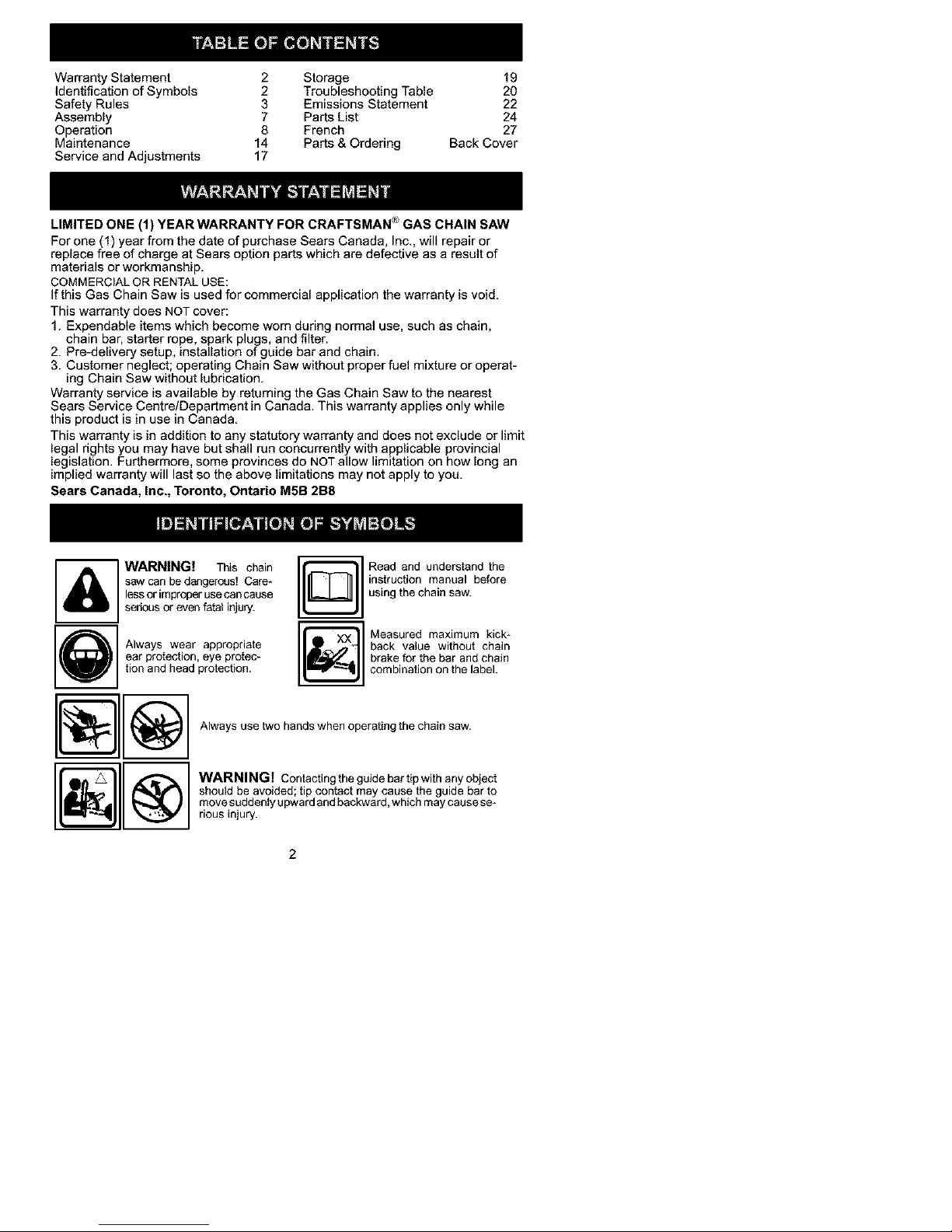
WARNING! This chain I _
saw can be dangerous! Care-
less or improper use can cause
serious or even fatal injury.
Always wear appropriate I _
ear protection, eye protec-
tion and head protection.
Read and understand the
instruction manual before
using the chain saw.
Measured maximum kick*
back value without chain
brake for the bar and chain
combination on the label.
Always use two hands when operating the chain saw.
WARNING! Contacting the guidebar tip with any object
should be avoided; tip contact may cause the guide bar to
• move suddenly upward and backward, which may cause so*
rious injury.
Page 3
_I.WARNING:Alwaysdisconnect
sparkplugwirewhenmakingrepairsex-
ceptforcarburetoradjustments.Be-
causeachainsawisahigh-speed
woodcuttingtool,specialsafetyprecau-
tionsmustbeobservedtoreduceriskof
accidents.Carelessorimpreperuseof
thistoolcancauseseriousinjury.
PLANAHEAD
• Restdcttheuseofyoursawtoadult
userswhounderstandandcanfollow
thesafetyrules,precautions,andop-
eretinginstructionsfoundinthis
manual.
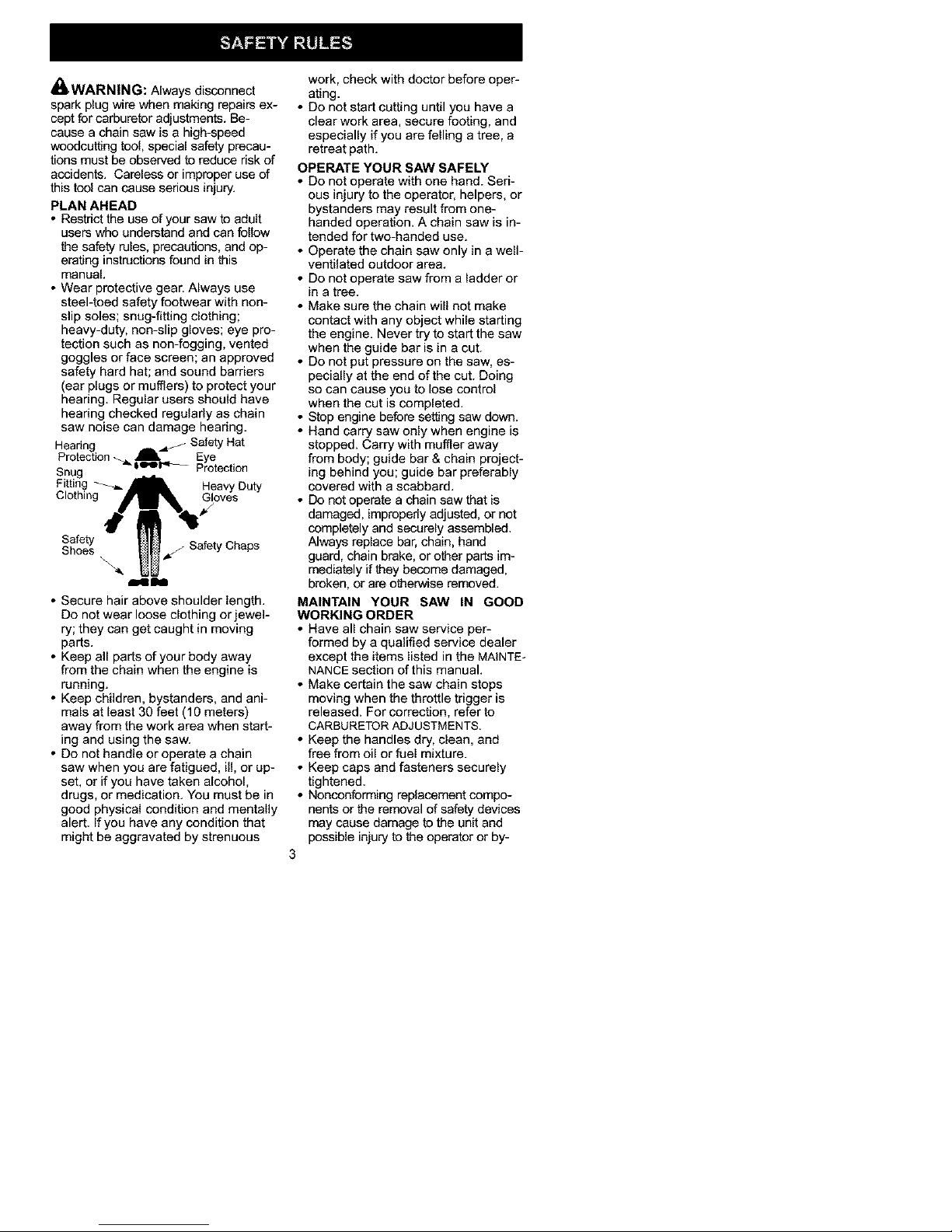
•Wearprotectivegear.Alwaysuse
steel-toedsafetyfootwearwithnon-
slipsoles;snug-fittingclothing;
heavy-duty,non-slipgloves;eyepro-
tectionsuchasnon-fogging,vented
gogglesorfacescreen;anapproved
safetyhardhat;andsoundbarriers
(earplugsormufflers)toprotectyour
hearing.Regularusersshouldhave
hearingcheckedregularlyaschain
sawnoisecandamagehearing.
Hearing i SafetyHat
Protection_. _ Eye
_ i_l._-_ Protection
Snug
Fitting- h" _lk_I__P'T Heavy Duty
Clothing Gloves
114 Illi
• Secure hair above shoulder length.
Do not wear loose clothing or jewel-
ry; they can get caught in moving
pads.
• Keep all parts of your body away
from the chain when the engine is
running.
• Keep children, bystanders, and ani-
mals at least 30 feet (10 meters)
away from the work area when start-
ing and using the saw.
• Do not handle or operate a chain
saw when you are fatigued, i11,or up-
set, or if you have taken alcohol,
drugs, or medication. You must be in
good physical condition and mentally
alert. If you have any condition that
might be aggravated by strenuous
work, check with doctor before oper-
ating.
• Do not start cutting until you have a
clear work area, secure footing, and
especially if you are felling a tree, a
retreat path.
OPERATE YOUR SAW SAFELY
• Do not operate with one hand. Seri-
ous injury to the operator, helpers, or
bystanders may result from one-
handed operation. A chain saw is in-
tended for two-handed use.
• Operate the chain saw only in a well-
ventilated outdoor area.
• Do not operate saw from a ladder or
in a tree.
• Make sure the chain will not make
contact with any object while starting
the engine. Never try to start the saw
when the guide bar is in a cut.
• Do not put pressure on the saw, es-
pecially at the end of the cut. Doing
so can cause you to lose control
when the cut is completed.
• Stop engine before setting saw down.
• Hand carry saw only when engine is
stopped. Carry with muffler away
from body; guide bar & chain project-
ing behind you; guide bar preferably
covered with a scabbard.
• Do not operate a chain saw that is
damaged, improperly adjusted, or not
completely and securely assembled.
Always replace bar, chain, hand
guard, chain brake, or other parts im-
mediately if they become damaged,
broken, or are otherwise removed.
MAINTAIN YOUR SAW IN GOOD
WORKING ORDER
• Have all chain saw service per-
formed by a qualified service dealer
except the items listed in the MAINTE-
NANCE section of this manual.
• Make certain the saw chain stops
moving when the throttle trigger is
released. For correction, refer to
CARBURETOR ADJUSTMENTS.
• Keep the handles dry, clean, and
free from oil or fuel mixture.
• Keep caps and fasteners securely
tightened.
• Nonconforming replacement compo-
nents or the removal of safety devices
may cause damage to the unit and
possible injury to the operator or by-
3
Page 4
standers.UseonlyCraftsmanacces-
soriesandreplacementpartsasrec-
ommended.Nevermodifyyoursaw.
• Maintainchainsawwithcare.
• Keepunitsharpandcleanforbetter
andsaferperformance.
• Followinstructionsforlubricatingand
changingaccessories.
•Checkfordamagedparts.Beforefur-
fl_eruseofthechainsaw,aguardor
otherpartthatisdamagedshouldbe
carefullycheckedtodeterminethatit
willoperatepreperiyandperfomqits
intendedfunction.Checkforalignment
ofmovingparts,bindingofmoving
parts,breakageofparts,mountingand
anyotherconditionsthatmayaffectits
operation.Aguardorotherpartthatis
damagedshouldbepreperiyrepaired
orreplacedbyaSearsServiceCentre
unlessotherwiseindicatedelsewhere
intheinstructionmanual.
•Whennotinuse,chainsawsshould
bestoredinadry,highorlocked-up
placeoutofthereachofchildren.
•Whenstoringsaw,useascabbardor
carryingcase.
HANDLE FUEL WITH CAUTION
• Do not smoke while handling fuel or
while operating the saw.
• Eliminate all sources of sparks or
flame in areas where fuel is mixed or
poured.
• Mix and pour fuel in an outdoor area
and use an approved, marked con-
tainer for all fuel purposes. Wipe up
all fuel spills before starting saw.
• Move at least 10 feet (3 meters) from
fueling site before starting.
• Turn the engine off and let saw cool
in a non-combustible area, not on
dry leaves, straw, paper, etc. Slowly
remove fuel cap and refuel unit.
• Store the unit and fuel in a cool, dry
well ventilated space where fuel va-
pors cannot reach sparks or open
flames from water heaters, electric
motors or switches, furnaces, etc.
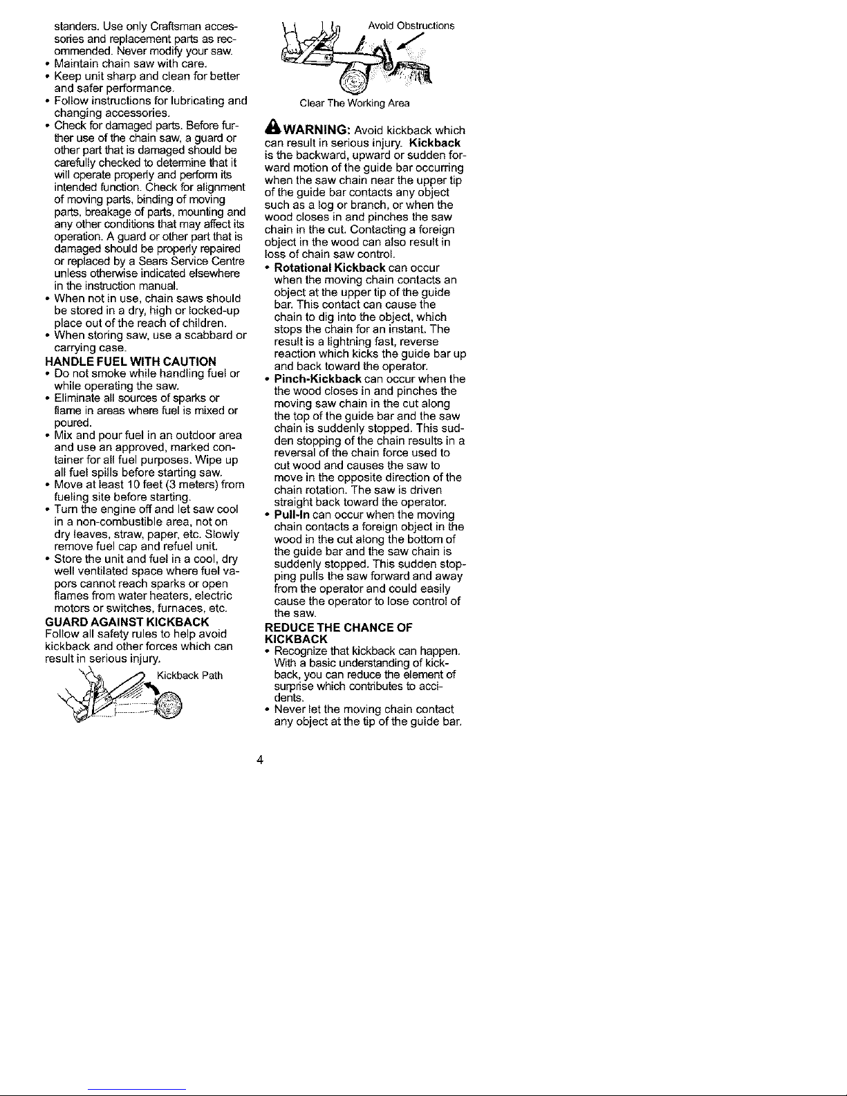
GUARD AGAINST KICKBACK
Follow all safety rules to help avoid
kickback and other forces which can
result in serious injury.
Kickback Path
_, _._ Avoid _,_uctions
Clear The Working Area
41_WARNING: Avoid kickback which
can result in serious injury. Kickback
is the backward, upward or sudden for-
ward motion of the guide bar occurring
when the saw chain near the upper tip
of the guide bar contacts any object
such as a log or branch, or when the
wood closes in and pinches the saw
chain in the cut. Contacting a foreign
object in the wood can also result in
loss of chain saw control.
• Rotational Kickback can occur
when the moving chain contacts an
object at the upper tip of the guide
bar. This contact can cause the
chain to dig into the object, which
stops the chain for an instant. The
result is a lightning fast, reverse
reaction which kicks the guide bar up
and back toward the operator.
• Pinch-Kickback can occur when the
the wood closes in and pinches the
moving saw chain in the cut along
the top of the guide bar and the saw
chain is suddenly stopped. This sud-
den stopping of the chain results in a
reversal of the chain force used to
cut wood and causes the saw to
move in the opposite direction of the
chain rotation. The saw is driven
straight back toward the operator.
• Pull-In can occur when the moving
chain contacts a foreign object in the
wood in the cut along the bottom of
the guide bar and the saw chain is
suddenly stopped. This sudden stop-
ping pulls the saw forward and away
from the operator and could easily
cause the operator to lose control of
the saw.
REDUCE THE CHANCE OF
KICKBACK
• Recognize that kickback can happen.
With a basic understanding of kick-
back, you can reduce the element of
surprise which contributes to acci-
dents.
• Never let the moving chain contact
any object at the tip of the guide bar.
Page 5
• Keepworkingareafreefromobstruc-
tionssuchasothertrees,branches,
rocks,fences,stumps,etc.Eliminate
oravoidanyobstructionthatyour
sawchaincouldhitwhilecutting.
•Whencuttingabranch,donotletthe
guidebarcontactanotherbranchor
otherobjectsaroundit.
• Keepsawchainsharpandproperly
tensioned.Alooseordullchaincan
increasethechanceofkickback.
Followmanufacturer'schainsharp-
eningandmaintenanceinstructions.
Checktensionatregularintervals,
butneverwithenginerunning.Make
surechainbrakenutsaresecurely
tightened.
• Beginandcontinuecuttingatfull
speed.Ifthechainismovingata
slowerspeed,thereisgreater
chanceofkickbackoccurring.
• Useextremecautionwhenreenter-
ingacut.
• Donotattemptcutsstartingwiththe
tipofthebar(plungecuts).
•Watchforshiftinglogsorotherforces
thatcouldcloseacutandpinchor
fallintochain.
• UsethespecifiedReduced-Kickback
GuideBarandLow-KickbackChain.
Avoid Pinch-Kickback:
• Be extremely aware of situations or
obstructions that can cause material
to pinch the top of or otherwise stop
the chain.
• Do not cut more than one log at a
time.
• Do not twist saw as bar is withdrawn
from an undercut when bucking.
Avoid Pull-In:
• Always begin cutting with the engine
at full speed and the saw housing
against wood.
• Use wedges made of plastic or
wood. Never use metal to hold the
cut open,
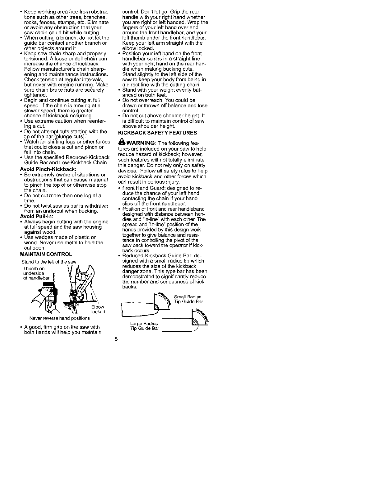
MAINTAIN CONTROL
Stand to the left of the saw
underside
_-_-_ t Elbow
ed
Never reverse hand positions
• A good, firm grip on the saw with
both hands will help you maintain
control, Don't let go, Grip the rear
handle with your right hand whether
you are right or left handed, Wrap the
fingers of your left hand over and
around the front handlebar, and your
left thumb under the front handlebar,
Keep your left arm straight with the
elbow locked.
• Position your left hand on the front
handlebar so it is in a straight line
with your right hand on the rear han-
dle when making bucking cuts.
Stand slightly to the left side of the
saw to keep your body from being in
a direct line with the cutting chain.
• Stand with your weight evenly bal-
anced on both feet.
• Do not overreach. You could be
drawn or thrown off balance and lose
control.
• Do not cut above shoulder height. It
is difficult to maintain control of saw
above shoulder height.
KICKBACK SAFETY FEATURES
_WARNING: The following fea-
tures are included on your saw to help
reduce hazard of kickback; however,
such features will not totally eliminate
this danger. Do not rely only on safety
devices. Follow all safety rules to help
avoid kickback and other forces which
can result in serious injury.
• Front Hand Guard: designed to re-
duce the chance of your left hand
contacting the chain if your hand
slips off the front handlebar.
• Position of front and rear handlebars:
designed with distance between han-
dles and "in-line" with each other. The
spread and "in-line" position of the
hands provided by this design work
together to give balance and resis-
tance in controlling the pivot of the
saw back toward the operator if kick-
back occurs,
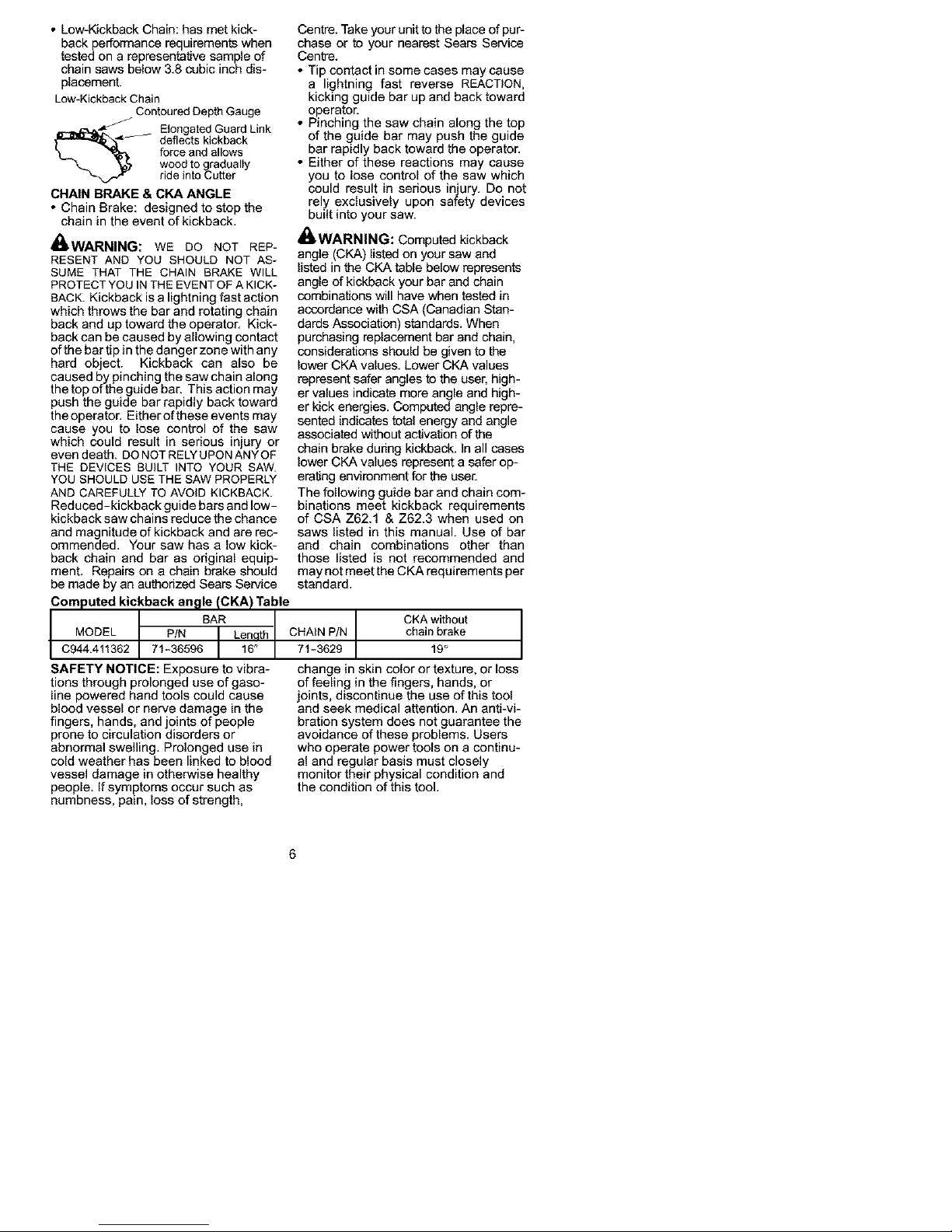
• Reduced-Kickback Guide Bar: de-
signed with a small radius tip which
reduces the size of the kickback
danger zone, This type bar has been
demonstrated to significantly reduce
the number and seriousness of kick-
backs.
_ Small Radius
Tip Guide Bar
Large Radius E '_
Tip Guide Bar
Page 6
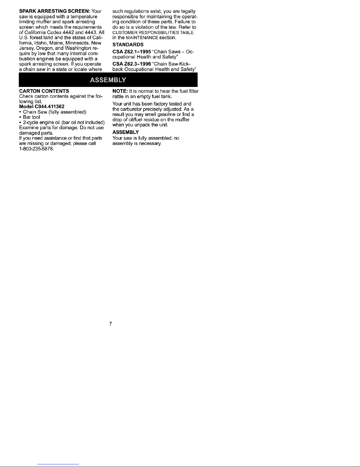
• Low-KickbackChain:hasmetkick-
backperformancerequirements when
tested on a representative sample of
chain saws below 3,8 cubic inch dis-
placement.
Low-Kickback Chain
Contoured Depth Gauge
_,_ longated Guard Link
deflects kickback
force and allows
wood to gradually
ride into Cutter
CHAIN BRAKE & CKA ANGLE
• Chain Brake: designed to stop the
chain in the event of kickback,
_WARNING: WE DO NOT REP*
RESENT AND YOU SHOULD NOT AS_
SUME THAT THE CHAIN BRAKE WILL
PROTECT YOU INTHE EVENT OF A KICK*
BACK. Kickback is a lightning fast action
which throws the bar and rotating chain
backand uptoward the operator. Kick-
back can be caused by allowing contact
of the bar tip in the danger zone with any
hard object. Kickback can also be
caused by pinching the saw chain along
the top of the guide bar, This action may
push the guide bar rapidly back toward
theoperator, Either of these events may
cause you to lose control of the saw
which could result in serious injury or
even death, DO NOT RELY UPON ANYOF
THE DEVICES BUILT INTO YOUR SAW.
YOU SHOULD USE THE SAW PROPERLY
AND CAREFULLY TO AVOID KICKBACK.
Reduced-kickback guide bars and low-
kickback saw chains reduce the chance
and magnitude of kickback and are rec-
ommended, Your saw has a low kick-
back chain and bar as original equip-
ment. Repairs on a chain brake should
be made by an authodzed Sears Service
Computed kickback an_lle (CKA) Table
BAR
MODEL P/N Len th
C944.411362 71-36596 _
IAFETY NOTICE: Exposure to vibra-
tions through prolonged use of gaso-
line powered hand tools could cause
blood vessel or nerve damage in the
fingers, hands, and joints of people
prone to circulation disorders or
abnormal swelling. Prolonged use in
cold weather has been linked to blood
vessel damage in otherwise healthy
people. If symptoms occur such as
numbness, pain, loss of strength,
Centre. Take your unit to the place of pur-
chase or to your nearest Sears Service
Centre.
• Tip contact in some cases may cause
a lightning fast reverse REACTION,
kicking guide bar up and back toward
operator.
• Pinching the saw chain along the top
of the guide bar may push the guide
bar rapidly back toward the operator.
• Either of these reactions may cause
you to lose control of the saw which
could result in serious injury. Do not
rely exclusively upon safety devices
built into your saw.
_WARNING: Computed kickback
angle (CKA) listed on your saw and
listed in the CKA table below represents
angle of kickback your bar and chain
combinations will have when tested in
accordance with CSA (Canadian Stan-
dards Association) standards. When
purchasing replacement bar and chain,
considerations should be given to the
lower CKA values. Lower CKA values
represent safer angles to the user, high-
er values indicate more angle and high-
er kick energies. Computed angle repre-
sented indicates total energy and angle
associated without activation of the
chain brake dudng kickback. In all cases
lower CKA values represent a safer op-
erating environment for the user.
The following guide bar and chain com-
binations meet kickback requirements
of CSA 2162.1 & Z62.3 when used on
saws listed in this manual. Use of bar
and chain combinations other than
those listed is not recommended and
may not meet the CKA requirements per
standard.
CKA without J
CHAIN P/N chain brake
71-3629 19°
change in skin color or texture, or loss
of feeling in the fingers, hands, or
joints, discontinue the use of this tool
and seek medical attention. An anti-vi-
bration system does not guarantee the
avoidance of these problems. Users
who operate power tools on a continu-
al and regular basis must closely
monitor their physical condition and
the condition of this tool.
Page 7
SPARK ARRESTING SCREEN: Your
saw is equipped with a temperature
limiting muffler and spark arresting
screen which meets the requirements
of California Codes 4442 and 4443. All
U.S. forest land and the states of Cali-
fornia, Idaho, Maine, Minnesota, New
Jersey, Oregon, and Washington re-
quire by law that many internal com-
bustion engines be equipped with a
spark arresting screen. If you operate
a chain saw in a state or locale where
such regulations exist, you are legally
responsible for maintaining the operat-
ing condition of these parts. Failure to
do so is a violation of the law. Refer to
CUSTOMER RESPONSIBILITIES TABLE
in the MAINTENANCE section.
STANDARDS
CSA Z62.1-1995 "Chain Saws - Oc-
cupational Health and Safety"
CSA Z62.3-1996 "Chain Saw Kick-
back Occupational Health and Safety"
CARTON CONTENTS
Check carton contents against the fol-
lowing list.
Model C944,411362
• Chain Saw (fully assembled)
• Bar tool
• 2-cycle engine oil (bar oil not included)
Examine parts for damage. Do not use
damaged parts.
If you need assistance or find that parts
are missing or damaged, please call
14_00-235-587&
NOTE: It is normal to hear the fuel filter
rattle in an empty fuel tank.
Your unit has been factory tested and
the carburetor precisely adjusted. As a
result you may smell gasoline or find a
drop of oil/fuel residue on the muffler
when you unpack the unit.
ASSEMBLY
Your saw is fully assembled; no
assembly is necessary.
Page 8

KNOW YOUR SAW
READ THIS iNSTRUCTION MANUAL AND SAFETY RULES BEFORE OPERATING YOUR
CHAIN SAW. Compare the illustrations with your unit to familiarize yourself with the
location of the various controls and adjustments. Save this manual for future ref-
erence.
Chain Hand Guard---_. Front Handle
Adjustment Too, r_ __/
_1 Starter Rope
k_ _S!I ON/StOP
Chain Switch
,__Pr_er
Bar Oil Fill Cap Housing Fuel Mix Fill Cap
Throttle Cylindir Cc,_"_ _
Lockout.-/-LYZI17
Rear _ _'_ d= Adjusting _ P_"_ J Chain
Handle _/"_..2"0_0_ Screw _ Direction
i z,Fj_i€
/_ "_'_-'--_'_"_ Chain Brake / _ S rocket
Throttle Choke Chain '_ Nuts Guide Bar _r HPole
Trigger Knob Brake Chain Catcher
ON/STOP SWITCH
The ON/STOP SWITCH is used to stop
the engine.
THROTTLE TRIGGER
The THROTTLE TRIGGER controls en-
gine speed.
THROTTLE LOCK-OUT
The THROTTLE LOCK-OUT must be
pressed before you can squeeze the
throttle trigger. This feature prevents
you from accidentally squeezing the
trigger.
CHOKE/FAST IDLE LEVER
The choke and fast idle are set by pull-
ing the CHOKE/FAST iDLE LEVER out
fully for cold or refueled starting. The
choke provides additional fuel to the
engine during cold starting.
PRIMER BULB
The PRIMER BULB circulates fuel to the
carburetor to provide quicker starting.
CHAIN BRAKE
The CHAIN BRAKE is a device de-
signed to stop the chain if kickback oc-
curs. The chain brake activates auto-
matically in the event of kickback. The
chain brake activates manually if the
front hand guard is pushed forward.
The chain brake is disengaged by pull-
ing the front hand guard back toward
the front handle as far as possible.
CHAIN TENSION
It is normal for a new chain to stretch
dudng first 30 minutes of operation. You
should check your chain tension fre-
quently. See CHAIN TENSION under the
SERVICE AND ADJUSTMENTS sec_on.
_WARNING: Muffler is very hot
during and after use. Do not touch the
muffler or allow combustible material
such as dry grass or fuel to do so.
Page 9

BEFORE STARTING ENGINE
_WARNING: Be sure to read the
fuel handling information in the safety
rules section of this manual before you
begin. If you do not understand the
fuel handling information do not at-
tempt to fuel your unit. Seek help from
someone that does understand the in-
formation or call the customer assis-
tance help line at 1-800-235-5878,
GUIDE BAR AND CHAIN OIL
The chain oiler provides continuous
lubrication to the chain and guide bar.
Be sure to fill the bar oil tank when you
fi[I the fuel tank (Capacity = 6.8 fL oz.),
For maximum guide bar and chain life,
we recommend you use Craftsman
chain saw bar oil, If Craftsman bar oil
is not available, you may use a good
grade SAE 30 oil until you are able to
obtain Craftsman brand. The oil output
is automatically metered during opera-
tion. Your saw will use approximately
one tank of bar oil for every tank of fuel
mix. Always fill the bar oil tank when
you fi[I the fuel tank.
FUELING ENGINE
_WARNING: Remove fuel cap
slowly when refueling,
This engine is certified to operate on
unleaded gasoline. Before operation,
gasoline must be mixed with a good
quality synthetic 2-cycle air-cooled en-
gine oil. We recommend Craftsman
brand synthetic oil, Mix gasoline and
oil at a ratio of 40:1. A 40:1 ratio is ob-
tained by mixing 95 ml ofoil with 4
litres of unleaded gasoline, Included
with this saw is a 95 ml container of
Craftsman brand oil. Pour the entire
contents of this container into 4 [itres of
gasoline to achieve the proper fuel
mixture. DO NOT USE automotive oil or
boat oil. These oils will cause engine
damage. When mixing fuel follow the
instructions printed on the container.
Once oil is added to the gasoline,
shake container momentarily to assure
that the fuel is thoroughly mixed. Al-
ways read and follow the safety rules
relating to fuel before fueling your unit.
IMPORTANT
Experience indicates that alcohol
blended fuels (called gasohol or using
ethanol or methanol) can attract mois-
ture which leads to separation and
formation of acids during storage. Acidic
gas can damage the fuel system of an
engine while in storage,
To avoid engine problems, the fuel sys-
tem should be emptied before storage
for 30 days or longer. Drain the gas
tank, start the engine and let it run until
the fuel lines and carburetor are empty,
Use fresh fuel next season. See STOR_
AGE instructions for additional informa-
tion.
Never use engine or carburetor clean-
er products in the fuel tank or perma-
nent damage may occur.
See the STORAGE section for addition-
al information.
CHAIN BRAKE
Ensure chain brake is disengaged by
pulling the front hand guard back to-
ward the front handle as far as pos-
sible. The chain brake must be disen-
gaged before cutting with the saw,
_WARNING: The chain must not
move when the engine runs at idle
speed, If the chain moves at idle
speed refer to CARBURETOR ADJUST*
MENT within this manual, Avoid con-
tact with the muffler. A hot muffler can
cause serious burns.
STOPPING YOUR ENGINE
• Move ON/STOP switch to the STOP
position.
ON/STOP SWITCH
ON
STARTING YOUR ENGINE
• To start the engine, hold the saw
firmly on the ground as illustrated.
Make sure the chain is free to turn
without contacting any object,
Starter Rope Handle
Ri( Foot Throu
Rear Handle
Important points to remember
When pulling the starter rope, do not
use the full extent of the rope as this
can cause the rope to break. Do not
let starter rope snap back. Hold the
handle and let the rope rewind slowly.
9
Page 10

Forcoldweatherstarting,starttheunit
atFULLCHOKE;allowtheengineto
warmupbeforesqueezingthethrottle
trigger.
NOTE:DONOTcutmaterialwiththe
choke/fastidleleverattheFULL
CHOKEposition.
STARTINGACOLDENGINE(ora
warm engine after running out of
fuel)
NOTE: In the following steps, when
the choke/fast idle lever is pulled out to
the full extent, the correct throttle set-
ting for starting is set automatically.
1. Move ON/STOP switch to ON posi-
tion.
2. Pull choke/fast idle lever out to the
full extent.
3. Slowly press primer bulb 6 times.
4. Pull the starter rope quickly with
your right hand 5 times. Then, pro-
ceed to the next step.
NOTE: If the engine sounds as if it is
trying to start before the 5th pull, stop
pulling and immediately proceed to the
next step.
5. Push the choke/fast idle lever in
completely (to the OFF CHOKE
position).
6. Pull the starter rope quickly with
your dght hand until the engine
starts.
7. Allow the engine to run for approxi-
mately 5 seconds. Then, squeeze
and release throttle trigger to allow
engine to return to idle speed.
ON/STOih _
Switch
Lever
CHOKE/FAST IDLE LEVER
e_ :IEW)
-?:
Chok It
FastIdle Lever OFF FULL
STARTING A WARM ENGINE
1. Move ON/STOP switch to ON posi-
tion.
2. Pull the chokelfast idle lever out to
the full extent, then push the lever
back in completely (to the OFF
CHOKE position).
3. Slowly press primer bulb 6 times.
4. Pull the starter rope quickly with
your right hand until the engine
starts.
5. Squeeze and release throttle trig-
ger, allowing engine to idle.
DIFFICULT STARTING (or starting a
flooded engine)
The engine may be flooded if it has not
started after 10 pulls.
Flooded engines can be cleared of ex-
cess fuel by following the warm engine
starting procedure listed above. Insure
the ON/STOP switch is in the ON position.
Starting could require many pulls de-
pending on how badly the unit is
flooded. If engine still fails to start, refer
to the TROUBLESHOOTING TABLE or
call 1-800-235-5878.
CHAIN BRAKE
_WARNING: If the brake band is
worn too thin it may break when the chain
brake is triggered. With a broken brake
band, the chain brake will not stop the
chain. The chain brake must be replaced
if any part is worn to less than 0.020 inch
(0.5 mm) thick. Repairs on a chain brake
should be made by your Sears Service
Centre. Take your unit to the place of pur-
chase or to the nearest Sears Service
Centre.
• This saw is equipped with a chain
brake. The brake is designed to stop
the chain if kickback occurs.
• The inertia-activated chain brake is
activated if the front hand guard is
pushed forward, either manually (by
hand) or automatically (by sudden
movement).
• If the brake is already activated, it is
disengaged by pulling the front hand
guard back toward the front handle as
far as possible.
• When cutting with the saw, the chain
brake must be disengaged.
Disengaged
Braking function control
CAUTION: The chain brake must be
checked several times daily. The engine
must be running when performing this
procedure. This is the only instance
when the saw should be placed on the
ground with the engine running.
10
Page 11

Placethesawonfirmground.Gripthe
rearhandlewithyourrighthandandthe
fronthandlewithyourlefthand.Apply
full throttlebyfullydepressingthe
throttletrigger.Activatethechainbrake
byturningyourleftwristagainstthe
handguardwithoutreleasingyourgrip
aroundthefronthandle.Thechain
shouldstopimmediately.
Inertia activating function control
_,WARNING: When performing the
following procedure, the engine must
be turned off.
Grip the rear handle with your right hand
and the front handle with your left hand.
Hold the chain saw approximately 14
inches (35 cm) above a stump or other
wooden surface. Release your grip on
the front handle and use the weight of
the saw to let the tip of the guide bar fall
forward and contact the stump. When
the tip of the bar hits the stump, the
brake should activate.
OPERATING TIPS
• Check chain tension before first use
and after 1 minute of operation. See
CHAIN TENSION in the MAINTENANCE
section.
• Cut wood only. Do not cut metal,
plastics, masonry, non-wood building
materials, etc.
• Stop the saw if the chain strikes a
foreign object. Inspect the saw and
repair parts as necessary.
• Keep the chain out of dirt and sand.
Even a small amount of dirt will
quickly dull a chain and increase the
possibility of kickback.
• Practice cutting a few small logs using
the following steps. This will help you
get the '_feel"of using your saw before
you begin a major sawing operation.
• Squeeze the throttle trigger and al-
low the engine to reach full speed
before cutting.
• Begin cutting with the saw frame
against the log.
• Keep the engine at full speed the
entire time you are cutting.
• Allow the chain to cut for you. Exert
only light downward pressure.
• Release the throttle trigger as soon
as the cut is completed, allowing
the engine to idle. If you run the
saw at full throttle without a cutting
load, unnecessary wear can occur.
• To avoid losing control when cut is
complete, do not put pressure on
saw at end of cut.
• Stop engine before setting saw down.
TREE FELLING TECHNIQUES
_WARNING: Check for broken or
dead branches which can fall while cut-
ting causing serious injury. Do not cut
near buildings or electrical wires if you
do not know the direction of tree fall, nor
cut at night since you will not be able to
see well, nor during bad weather such
as rain, snow, or strong winds, etc.
• Carefully plan your sawing operation
in advance.
• Clear the work area. You need a
clear area all around the tree so you
can have secure footing.
• The chain saw operator should keep
on the uphill side of the terrain as the
tree is likely to roll or slide downhill
after it is felled.
• Study the natural conditions that can
cause the tree to fall in a particular
direction. These conditions include:
• The wind direction and speed.
• The lean of the tree. The lean of a
tree might not be apparent due to
uneven or sloping terrain. Use a
plumb or level to determine the di-
rection of tree lean.
• Weight and branches on one side.
• Surrounding trees and obstacles.
• Look for decay and rot. If the trunk is
rotted, it can snap and fall toward the
operator.
• Make sure there is enough room for
the tree to fall. Maintain a distance of
2-1/2 tree lengths from the nearest
person or other objects. Engine
noise can drown out a warning call.
• Remove dirt, stones, loose bark,
nails, staples, and wire from the tree
where cuts are to be made.
Plan a clear retreat path
;t""""t)" _ - Direction of Fall
FELLING LARGE TREES
(6 inches in diameter or larger)
The notch method is used to fell large
trees. A notch is cut on the side of the
tree in the desired direction of fall. After
11
Page 12

a felling cut is made on the opposite
side of tree, the tree will tend to fall in
the direction of the notch.
NOTE: If tree has large buttress roots,
remove them before making the notch.
If using saw to remove buttress roots,
keep saw chain from contacting
ground to prevent dulling of the chain.
NOTCH CUT AND FELLING TREE
• Make notch cut by cutting the top of
the notch first. Cut through 1/3 of the
diameter of the tree. Next complete
the notch by cutting the bottom. See
illustration. Once the notch is cut, re-
move the wedge of wood from tree.
Felling cut here
First cut 2.I
Se_ /.__ /_.__ _nge
• After removing the wood, make the
felling cut on the opposite side of the
notch. This is done by making a cut
about two inches higher than the
Centre of the notch. This will leave
enough uncut wood between the fell-
ing cut and the notch to form a hinge.
This hinge will help prevent the tree
from falling in the wrong direction.
Hinge holds tree on
stump and helps
Opening of
felling cut
Closing
of notch
NOTE: Before felling cut is complete,
use wedges to open the cut when
necessary to control the direction of
fall. To avoid kickback and chain
damage, use wood or plastic wedges,
but never steel or iron wedges.
• Be alert to signs that the tree is
ready to fall: cracking sounds, widen-
ing of the felling cut, or movement in
the upper branches.
• As tree starts to fall, stop saw, put it
down, and get away quickly on your
planned retreat path.
• DO NOT use your saw to cut down a
partially fallen tree. Be extremely
cautious with partially fallen trees
that may be poorly supported. When
a tree doesn't fall completely, set the
saw aside and pull down the tree
with a cable winch, block and tackle,
or tractor.
CUTTING A FALLEN TREE
(BUCKING)
Bucking is the term used for cutting a
fallen tree to the desired log size.
_WARNING: Do not stand on the
log being cut. Any portion can roll
causing loss of footing and control. Do
not stand downhill of the log being cut.
IMPORTANT POINTS
• Cut only one log at a time.
• Cut shattered wood very carefully;
sharp pieces of wood could be flung
toward operator.
• Use a sawhorse to cut small logs.
Never allow another person to hold
the log while cutting and never hold
the log with your leg or foot.
• Do not cut in an area where logs,
limbs, and roots are tangled. Drag logs
into a clear area before cutting them.
BUCKING TECHNIQUES
_WARNING: If saw becomes
pinched or hung in a log, don't try to
force it out. You can lose control of the
saw resulting in injury and/or damage
to the saw. Stop the saw, drive a
wedge of plastic or wood into the cut
until the saw can be removed easily. Re-
start saw and carefully reenter the cut.
Do not use a metal wedge. Do not at-
tempt to restart your saw when it is
pinched or hung in a log.
Use a wedge to remove pinched saw
Turn saw OFF and use a plastic or
wooden wedge to force cut open.
Overcutting begins on the top side of
the log with the bottom of the saw
against the log. When overcutting use
light downward pressure.
Overcutting Undercutting
Undercutting involves cutting on the
underside of the log with top of saw
against the log. When undercutting
12
Page 13

uselightupwardpressure.Holdsaw
firmlyandmaintaincontrol.Thesaw
willtendtopushbacktowardyou.
_WARNING:Neverturnsawup-
sidedowntoundercut.Thesawcan-
notbecontrolledinthisposition.
Alwaysmakeyourfirstcutonthe
compressionsideofthelog.Thecom-
pressionsideofthelogiswherethe
pressureofthelog'sweightisconcen-
trated.
First cut on compression side of log
Second cut
First cut on compression side of log
BUCKING WITHOUT A SUPPORT
• Overcut through 1/3 of the diameter
of the log,
• Roll the log over and finish with a
second overcut,
• Watch for togs with a compresion
side. See illustrations for cutting logs
with a compression side.
BUCKING USING A LOG OR
SUPPORT STAND
• Remember your first cut is always on
the compression side of the log. (Re-
fer to the illustrations below for your
first and second cut).
• Your first cut should extend 1/3of the
diameter of the log.
• Finish with your second cut.
Using a log for support
2ndCut
%t
1st Cut
Using a_nd Cut
L st
t cut
t cot_ .
LIMBING AND PRUNING
,_WARNING: Be alert for and guard
against kickback, Do not allow _qe mov-
ing chain to contact any other branches
or objects at the nose of the guide bar
when limbing or pruning. Allowing such
contact can result in sedous injury.
_WARNING: Never climb into a
tree to limb or prune. Do not stand on
ladders, platforms, a log, or in any po-
sition which can cause you to lose
your balance or control of the saw.
IMPORTANT POINTS
• Watch out for springpoles.
Springpotas are small size limbs
which can whip toward you, or pull
you off balance. Use extreme cau-
tion when cutting small size limbs.
• Be alert for springback. Watch out for
branches that are bent or under
pressure. Avoid being struck by the
branch or the saw when the tension
in the wood fibers is released.
• Frequently clear branches out of the
way to avoid tripping over them.
LIMBING
• Limb a tree only after it is cut down.
• Leave the larger limbs underneath
the felled tree to support the tree as
you work.
• Start at the base of the felled tree
and work toward the top, cutting
branches and limbs. Remove small
limbs with one cut.
• Keep the tree between you and the
chain.
• Remove larger, supporting branches
with the cutting techniques described
in BUCKING WITHOUT A SUPPORT.
• Always use an overcut to cut small
and freely hanging limbs. Undercut-
ting could cause limbs to fall and
pinch the saw.
13
Page 14

PRUNING
_WARNING: Limit pruning to limbs
shoulder height or below. Do not cut if
branches are higher than your shoul-
der. Get a professional to do the job.
• Make your first cut 1/3 of the way
through the bottom of the limb. This
cut will make the limb sag so that it
falls easily on the second cut.
• Next make a second cut an overcut
all the way through the limb,
• Finish the pruning operation by using
an overcut so that the stump of the
limb protrudes 1 to 2 inches from the
trunk of the tree.
Second cut
3rd cut 1to2 in.
from trunk of tree
CUSTOMER RESPONSIBILITIES
_WARNING: Disconnect the spark plug before performing maintenance
except for carburetor adjustments.
Fill in dates as you complete Befon After Ever Every Service
regular service Use Use 5hrs 25hrs. Yearly Dates
Check for damaged/worn parts _,
Check for loose fasteners/parts _'
Check chain tension ._"
Check chain sharpness -_"
Check guide bar _'
Check fuel mixture level -_"
Check guide bar and chain oil _'
Inspect and clean unit & decals ._"
Check chain brake ._"
Clean guide bar groove ._"
Clean air filter ._"
Clean/inspect mumer and spark
arresting screen
Replace spark plug and fuel filter _'
_ENERAL RECOMMENDATIONS
The warranty on this unit does not cov-
er items that have been subjected to
operator abuse or negligence. To re-
ceive full value from the warranty, the
operator must maintain unit as instruct-
ed in this manual. Various adjustments
will need to be made periodically to
properly maintain your unit.
• Once a year, replace the spark plug.
air filter element, and check guide bar
and chain for wear. A new spark plug
and air filter element assures proper
air-fuel mixture and helps your engine
run better and last longer.
CHECK FOR DAMAGED OR
WORN PARTS
Contact Sears Service Centre for re-
placement of damaged or worn parts.
NOTE: It is normal for a small amount
of oil to appear under the saw after en-
gine stops. Do not confuse this with a
leaking oil tank.
• ON/STOP Switch - Ensure ON/STOP
switch functions properly by moving
14
Page 15

the switch to the STOP position.
Make sure engine stops; then restart
engine and continue.
• Fuel Tank - Do not use saw if fuel
tank shows signs of damage or leaks.
• Oil Tank - Do not use saw ifoil tank
shows signs of damage or leaks.
CHECK FOR LOOSE
FASTENERS AND PARTS
Chain Brake Nuts
Chain
Muffler
Cylinder Shield
Air Filter
Handle Screws
Vibration Mounts
Starter Housing
Front Hand Guard
CHECK CHAIN TENSION
_WARNING: Wear protective
gloves when handling chain. The
chain is sharp and can cut you even
when it is not moving.
Chain tension is very important. Chains
stretch during use. This is especially
true during the first few times you use
your saw. Always check chain tension
each time you use and refuel your saw.
1. Use the screwdriver end of the
chain adjustment tool (bar tool) to
move chain around guide bar to
ensure kinks do not exist. The
chain should rotate freely.
Chain Brake Screw (Bar Tool)
Nuts
2. Loosen chain brake nuts until they
are finger tight against the chain
brake.
3. Turn adjusting screw clockwise un-
til chain solidly contacts bottom of
guide bar rail.
Adjusting
Screw
4. Using bar tool, rcll chain around
guide barto ensure all links are in
bar groove.
5. Lift up tip of guide bar to check for
sag. Release tip of guide bar, then
turn adjusting screw until sag does
not exist.
6. While lifting tip of guide bar, tighten
chain brake nuts securely with the
bar tool.
7. Use the screwdriver end of the bar
tool to move chain around guide
bar.
8. If chain does not rotate, it is too tight.
Slightly loosen chain brake nuts and
loosen chain by turning the adjusting
screw counterclockwise. Refighten
chain brake nuts.
9. If chain is too loose, it will sag be-
low the guide bar. DO NOT operate
the saw if the chain is loose.
zt _
41_WARNING: If the saw is operated
with a loose chain, the chain could
jump off the guide bar and result in se-
rious injury.
CHECK CHAIN SHARPNESS
A sharp chain makes wood chips. A
dull chain makes a sawdust powder
and cuts slowly. See CHAIN SHARP*
ENING in the SERVICE AND ADJUST-
MENTS section.
CHECK GUIDE BAR
Conditions which require guide bar
maintenance:
• Saw cuts to one side or at an angle.
• Saw has to be forced through the cut.
• Inadequate supply ofoil to bar/chain.
Check the condition of guide bar each
time chain is sharpened. A worn guide
bar will damage the chain and make
cutting difficult.
After each use, ensure ON/STOP switch
is in the STOP position, then clean all
sawdust from the guide bar and sprock-
et hole.
To maintain guide bar:
• Move ON/STOP switch to STOP.
• Loosen and remove chain brake
nuts and chain brake. Remove bar
and chain from saw.
15
Page 16

• Clean the oil holes and bar groove
after each 5 hours of operation.
Remove Sawdust From
Guide Bar _o_
Oil Holes .
• Burdng of guide bar rails is a normal
process of rail wear. Remove these
burrs with a flat file.
• When rail top is uneven, use a flat
file to restore square edges and
sides.
]_._ File Rail Edges_ _._
and Sides
Square
Worn Groove Correct Groove
Replace guide bar when the groove is
worn, the guide bar is bent or cracked,
or when excess heating or burring of
the rails occurs. If replacement is nec-
essary, use only the guide bar speci-
fied for your saw in the repair parts list
or on the decal located on the chain
saw.
CHECK FUEL MIXTURE LEVEL
• See FUELING ENGINE under the OP-
ERATION section.
LUBRICATION
Bar Oil
_Fill,_._Cap
_. . .,,.. . --
• See GUIDE BAR AND CHAIN OIL un-
der the OPERATION section.
INSPECT AND CLEAN UNIT
AND DECALS
• After each use, inspect complete unit
for loose or damaged parts. Clean
the unit and decals using a damp
cloth with a mild detergent.
• Wipe off unit with a clean dry cloth.
CHECK CHAIN BRAKE
• See CHAIN BRAKE in the OPERATION
section.
CLEAN AIR FILTER
A dirty air filter decreases the life and
performance of the engine and in-
creases fuel consumption and harmful
emissions. Always clean your air filter
after 15 tanks of fuel or 5 hours of op-
eration, whichever comes first. Clean
more frequently in dusty conditions. A
used air filter can never be completely
cleaned. It is advisable to replace your
air filter with a new one after every 50
hours of operation, or annually, which-
ever comes first. To clean filter:
1. Loosen 3 screws on cylinder cover.
2.
3.
4.
5.
6.
7.
Remove cylinder cove£
Remove air filter.
Clean the air filter using hot soapy
water. Rinse with clean cool water.
Air dry completely before reinstak
ling.
Lightly oil air filter before installing
toimprove the efficiency of air filter.
Use 2-cycle engine oil or motor oil
(SAE 30). Squeeze excess o11from
filter.
Reinstall air filter.
Reinstall cylinder cover and 3
screws. Tighten securely.
_- Cylinder Cover
Air Filter ..z_ / Screws
Cy,, ?ger
INSPECTMUFFLERAND SPARKAR-
RESTING SCREEN
As the unit is used, carbon deposits
build up on the muffler and spark ar-
resting screen, and must be removed
to avoid creating a fire hazard or af-
fecting engine performance.
Replace the spark arresting screen if
breaks occur.
Muffler Diffuser
Spark
Arresting
Screen
Muffler
Cover
Screw_
Body Muffler
Cover
CLEANING THE SPARK
ARRESTING SCREEN
Cleaning is required every 25 hours of
operation or annually, whichever
comes first.
1. Loosen and remove the 2 mumer
cover screws.
2. Remove the muffler cover (cover
snaps off mumer body).
16
Page 17

3. Remove muffler diffuser and sperk
arresting screen assembly. Notice
the orientation of parts for reas-
sembling.
4. Clean the spark arresting screen
with a wire brush. Replace screen
if breaks are found.
5. Replace any broken or cracked
muffler parts.
6. Reinstall diffuser and sperk arrest-
ing screen assembly with round
holes facing up.
7. Reinstall muffter cover and 2
screws. Tighten securely.
REPLACE SPARK PLUG
The spark plug should be replaced
each year to ensure the engine starts
easier and runs better. Ignition timing
is fixed and nonadjustable.
1. Loosen 3 screws on cylinder cover.
2. Remove the cylinder cover.
3. Pull off the sperk plug boot.
4. Remove spark plug from cylinder
and discard.
5. Replace with Champion CJ-7Y
spark plug and tighten securely
with a 3/4 inch socket wrench.
Spark plug gap should be 0.025 in.
6. Reinstall the spark plug boot.
7. Reinstall the cylinder cover and 3
screws. Tighten securely.
Screw_ Cylinde
Plug Boot
Plug
REPLACE FUEL FILTER
To replace the fuel filter, drain your unit
by running it dry of fuel Remove fuel
cap and its connected retainer from
tank. Pull filter from tank and remove
from line. Replace and reassemble.
aWARNING: Disconnect the spark
plug before performing maintenance,
service, or adjustments except for car-
buretor adjustments.
CHAIN SHARPENING
Chain sharpening requires special
tools. You can purchase sharpening
tools at Sears or go to a professional
chain sharpener.
CHAIN REPLACEMENT
_WARNING: Wear protective
gloves when handling chain. The
chain is sharp and can cut you even
when it is not moving.
It is normal for a new chain to stretch
during the first 15 minutes of operation.
You should recheck your chain tension
frequency and adjust the chain tension
as required. See CHAIN TENSION sec-
tion.
Replace the old chain when it be-
comes worn or damaged. Use only the
Low-Kickback replacement chain spe-
cified in the repair parts list. The cor-
rect replacement bar and chain is also
specified on a decal located on the
chain saw.
See your Sears Service Centre to ra-
place and sharpen individual cutters
on your chain.
TO REPLACE CHAIN:
1. Move ON/STOP switch to the STOP
position,
2. Remove chain brake nuts.
3. Remove chain brake.
Chain
Brake
Chain Brake
Nuts
4. Turn ad usting scraw on bar coun-
terc ockw se to move the tens on-
ing rack as far as it will go toward
the front of the bar.
Tenson ngR
5. Slide guide bar behind clutch drum
until guide bar stops against clutch
drum sprocket.
17
Page 18

6. Remove the old chain.
7. Carefully remove new chain from
package. Hold chain with the drive
links as shown.
Cutters Depth Gauge
Drive Links
8. Place chain over and behind
clutch, fitting the drive links into the
clutch drum sprocket.
9. Fit bottom of drive links between
the teeth in the sprocket in the
nose of the guide bar.
10. Fit chain drive links into bar
groove.
11. Pull guide bar forward until chain is
snug in the guide bar groove. En-
sure all drive links are in the bar
groove.
12. Install the chain brake.
13. Install chain brake nuts; finger
tighten only. Do not tighten any fur-
ther at this point. Proceed to CHAIN
ADJUSTMENT
CHAIN ADJUSTMENT
See CHAIN TENSION in MAINTENANCE
section.
CARBURETOR ADJUSTMENT
_,WARNING: The chain wilt be
moving during most of this procedure.
Wear your protective equipment and
observe all safety precautions. During
the low speed mixture adjustment, re-
check idle speed after each turn of the
screw. The chain must not move at idle
speed.
Carburetor adjustment is critical and if
done improperly can permanently
damage the engine as well as the car-
buretor. If you require further assis-
tance or are unsure about performing
this procedure, call our customer as-
sistance help line at 1-800-235-5878.
Old fuel, a dirty air filter, dirty fuel filter,
or flooding may give the impression of
an improperly adjusted carburetor.
Check these conditions before adjust-
ing the carburetor.
The carburetor has been carefully set
at the factory. Adjustments may be
necessary if you notice any of the fol-
lowing conditions:
• Chain moves at idle. See IDLE
SPEED-T under adjusting procedure.
• Saw will not idle. See IDLE SPEED-T
and LOW SPEED MIXTURE-L under
adjusting procedure.
• Engine dies or hesitates when it
should accelerate. See ACCELERA*
TION CHECK under adjusting
procedure.
• Loss of cutfing power. See HIGH
SPEED MIXTURE-H under adjusting
procedure.
There are three adjustment screws on
the carburetor. They are labeled H, L,
and T. They are located in the area just
above the primer bulb.
ADJUSTING PROCEDURE
CAUTION: Do not force the plastic
limiter caps beyond the built-in stops
or damage will occur.
Initial Settings
1. Turn both mixture screws (L and H)
counterclockwise until they stop.
2. Turn the idle speed screw (T)
clockwise until it stops. Then turn it
counterclockwise 4 and 1/2 turns.
3. Start engine and let it run for 3 min-
utes, then proceed to adjust
screws according to the instruc-
tions below. If engine performance
at initial settings is acceptable, no
further adjustments are necessary.
If engine does not start, refer to the
TROUBLESHOOTING TABLE. If still
unable to remedy situation, call
1-800-235-5878.
Idle Speed-T
Allow engine to idle. If the chain
moves, idle is too fast. If the engine
stalls, idle is too slow. Adjust speed
until engine runs without chain move-
ment (idle too fast) or stalling (idle too
slow).
• Turn idle screw (T) clockwise to in-
crease engine speed.
• Turn idle screw (T) counterclockwise
to decrease engine speed.
Low Speed Mixture-L
Allow engine to idle. Then accelerate
the engine and note performance. If
engine hesitates, bogs down, or
smokes during acceleration, turn low
speed mixture screw (L) clockwise in
1/16-turn increments until performance
is satisfactory. Repeat this procedure
as necessary for proper adjustment.
After completing adjustments, check
for acceleration and chain movement
at idle. Reset if necessary.
18
Page 19

High Speed Mixture-H
DO NOT operate engine at full throttle
for prolonged periods while making ad-
justments. Damage to the engine can
occur. Make a test cut. Based on per-
formance of the saw while cutting, ad-
just the high speed mixture setting in
1/16-turn increments as follows:
• Turn the high speed mixture screw (H)
clockwise until saw has good power in
the cut with no hesitation. Do not ad-
just by sound or speed, but judge by
how well the saw performs in the cut.
• Turn the high speed mixture screw
(H) counterclockwise if the saw has
speed, but dies in the cut or lacks
power in the cut.
After completing adjustments, check
for acceleration and chain movement
at idle. Reset if necessary.
Acceleration Check
Ifthe engine dies or hesitates instead of
accelerating, turn the low speed mixture
screw (L) counterclockwise until you
have smooth acceleration with no chain
movement at idle.
zt _
41_WARNING: Perform the following
steps after each use:
• Allow the engine to cool, and secure
the unit before storing or transport-
ing.
• Store chain saw and fuel in a well
ventilated area where fuel vapors
cannot reach sparks or open flames
from water heaters, electric motors or
switches, furnaces, etc.
• Store chain saw with all guards in
place and position chain saw so that
any sharp object cannot accidentally
cause injury.
• Store chain saw well out of the reach
of children.
SEASONAL STORAGE
Prepare your unit for storage at the
end of the season or if it will not be
used for 30 days or more.
If your chain saw is to be stored for a
period of time:
• Clean saw thoroughly before stor-
age.
• Store in a clean dry area.
• Lightly oil external metal surfaces
and guide bar.
• Oil the chain and wrap it in heavy pa-
per or cloth.
FUEL SYSTEM
Under FUELING ENGINE in the OPERA_
TION section of this manual, see mes-
sage labeled IMPORTANT regarding
the use of gasohol in your chain saw.
Fuel stabilizer is an acceptable alter-
native in minimizing the formation of
fuel gum deposits during storage. Add
stabilizer to the gasoline in the fuel
tank or fuel storage container. Follow
the mix instructions found on stabilizer
containers. Run engine at least 5 min-
utes after adding stabilizer.
Craftsman 40:1,2-cycle engine oil (air
cooled) is especially blended with fuel
stabilizer. If you do not use this Sears
oil, you can add a fuel stabilizer to your
fuel tank.
ENGINE
• Remove spark plug and pour 1 tea-
spoon of 40:1, 2-cycle engine oil (air
cooled) through the spark plug open-
ing. Slowly pull the starter rope 8 to
10 times to distribute oil.
• Replace spark plug with new one of
recommended type and heat range.
• Clean air filter.
• Check entire unit for loose screws,
nuts, and bolts. Replace any dam-
aged, broken, or worn parts.
• At the beginning of the next season,
use only fresh fuel having the proper
gasoline to oil ratio.
OTHER
• Do not store gasoline from one sea-
son to another.
• Replace your gasoline can if it starts
to rust.
19
Page 20

TROUBLESHOOTING TABLE
_j. WARNING: Always stop unit and disconnect spark plug before perform-
ing all of the recommended remedies below except remedies that require
TROUBLE REMEDY
1. Move ON/STOP switch toON.
Engine will not
start or will run
only a few
seconds after
starting.
Engine will
not idle
properly.
Engine will not
accelerate,
lackspoweB
ordies under
_load.
Engine
smokes
excessively.
Engine runs
hot.
operation of the unit.
CAUSE
f. ON/STOP switch in
STOP position.
2. Engine flooded.
3. Fuel tank empty.
4. Spark plug not firing.
5. Fuel notreaching
carburetor.
6. Carburetor requires
adjustment.
7. None of the above.
1. Idle speed set too high
or too low.
2. Low Speed Mixture
requires adjustment.
3. Crankshaft seals worn.
4. Compression low.
5. None of the above.
1.Air filter dirty.
2. Spark plug fouled.
3. Carburetor requires
adjustment.
4. Exhaust ports or muf*
fler outlets plugged.
5. Compression low.
6. Chain brake engaged.
7. Noneof the above.
1. Choke partially on.
2. Fuel mixture incorrect.
3. Air filter dirty.
4. High Speed Mixture
requires adjustment.
5. Crankcase leak.
1. Fuel mixture incorrect.
2. Spark plug incorrect.
3. High Speed Mixture
set too lean.
4. Exhaust ports or muf-
fief outlets plugged.
5. Carbon build-up on
spark arresting screen.
6. Starter housing dirty
7. None of the above.
2. See"Difficult Starting" in the
Operation Section.
3. Fill tank with correct fuel mixture.
4. Install new spark plug.
5. Check for dirty fuel filter; replace.
Check for kinked or split fuel line;
repair or replace.
6. See"Carburetor Adjustment" in the
Service and Adjustments Section.
7. Contact Sears Service (see back cover).
1. See "Carburetor Adjustment" in the
Service and Adjustments Section.
2. See "Carburetor Adjustment" in the
Service and Adjustments Section.
3. Contact Sears Service (see back cover).
4. Contact Sears Service (see back cover).
5. Contact Sears Service (see back cover).
1. Clean or replace air filter.
2. Clean or replace plug and regap.
3. See "Carburetor Adjustment" in the
Service and Adjustments Section.
4. Contact Sears Service (see back cover).
5. Contact Sears Service (see back cover).
6. Disengage chain brake.
7. Contact Sears Service (see back cover).
1. Adjust choke.
2. Empty fuel tank and refill with
correct fuel mixture.
3. Clean or replace air filter.
4. See "Carburetor Adjustment" in the
Service and Adjustments Section.
5. Contact Sears Service (see back cover).
1. See "Fueling Engine" inthe Operation
section.
2. Replace with correct plug.
3. See "Carburetor Adjustment" in the
Service and Adjustments Section.
4. Contact Sears Service (see back cover).
5. Clean spark arresting screen.
6. Clean starter housing area.
7. Contact Sears Service (see back cover).
2O
Page 21

TROUBLESHOOTING TABLE - Continued
TROUBLE CAUSE REMEDY
Oi_inadequate 1. Oil tank empty. 1. Fill oil tank.
for bar and 2. Oil pump oroil filter 2. Contact Sears Service (see back cover).
chain clogged.
lubrication. 3. Guide bar oil hole 3. Remove bar and clean.
blocked.
Chain moves at 1. Idle speed requires 1. See"CarburetorAdjustment" in the
idle speed, adjustment. Service and Adjustments Section.
2. Clutch requires repair. 2. Contact Sears Service (see back cover).
Chain does not 1. Chain tension too 1.See"Check Chain Tension" in the
move when en- tight. Maintenance Section.
gine is acceler* 2. Carburetor requires 2. See"Carburetor Adjustment" in the
ated. adjustment. Service andAdjustments Section.
3. Guide bar rails 3. Repair or replace.
pinched.
4. Clutch slipping. 4. Contact Sears Service (see back cover).
5. Chain brake engaged. 5. Disengage chain brake.
Chain clatters 1. Chain tension incorrect.
or cuts roughly.
Chain stops
within the cut.
Chain cuts at
an angle.
2. Cutters damaged.
3. Chain worn.
4. Cutters dull, improperly
sharpened, or depth
gauges too high.
5. Sprocket worn.
6. Chain installed
backwards.
1. Chain cutter tops not
filed flat.
2. Guide bar burred or
bent; rails uneven.
3.Clutch slipping.
1. Cutters damaged on
one side.
2. Chain dull on one side.
3. Guide bar bent or worn.
1. See "Check Chain Tension" in the
Maintenance Section.
2. Contact Sears Service (see back cover).
3. Resharpen or replace chain.
4. See "Chain Sharpening" in the
Service and Adjustments Section.
5. Contact Sears Service (see back cover).
5. Install chain in right direction.
1. See "Chain Sharpening" in the
Service and Adjustments Section.
2. Repair or replace guide bar.
3. Contact Sears Service (see back cover).
1.See "Chain Sharpening" inthe
Service and Adjustments Section.
2. See "Chain Sharpening" in the
Service and Adjustments Section.
3. Replace guide bar.
If situations occur which are not covered in this manual, use care and good
judgement, If you need assistance, contact Sears Service or the CUSTOMER
ASSISTANCE HELPUNE at 1-800-235-5878.
21
Page 22

YOUR WARRANTY RIGHTS AND
OBLIGATIONS: The U. S. Environ-
mental Protection Agency/Environ-
ment Canada and Sears Canada, Inc.,
are pleased to explain the emissions
control system warranty on your year
2001-2004 small off-road engine.
Sears Canada must warrant the emis-
sion control system on your small off-
road engine for the pedods of time listed
below provided there has been no
abuse, neglect, or improper mainte-
nance of your small off-reed engine.
Your emission control system includes
parts such as the carburetor and the
ignition system. Where a warrantable
condition exists, Sears Canada will re-
pair your small off-reed engine at no
cost to you. Expenses covered under
warranty include diagnosis, parts and
labor. MANUFACTURER'S WARRAN-
TY COVERAGE: If any emissions re-
lated part on your engine (as listed un-
der Emissions Control Warranty Parts
List) is defective or a defect in the mate-
dals or workmanship of the engine
causes the failure of such an emission
related part, the part will be repaired or
replaced by Sears Canada. OWNER'S
WARRANTY RESPONSIBILITIES: As
the small off-road engine owner, you
are responsible for the performance of
the required maintenance listed in your
instruction manual. Sears Canada rec-
ommends that you retain all receipts
covedng maintenance on your small off-
road engine, but Sears Canada cannot
deny warranty solely for the lack of re-
ceipts or for your failure to ensure the
performance of all scheduled mainte-
nance. As the small off-road engine
owner, you should be aware that Sears
Canada may deny you warranty cover-
age if your small off-reed engine or a
part of it has failed due to abuse, ne-
glect, improper maintenance, unap-
proved modifications, or the use of parts
not made or approved by the odginal
equipment manufacturer. You are re-
sponsible for presenting your small off-
road engine to a Sears Canada autho-
dzed repair center as soon as a problem
exists. Warranty repairs should be com-
pleted in a reasonable amount of time,
not to exceed 30 days. If you have any
questions regarding your warranty dghts
and responsibilities, you should contact
your nearest authodzed service center
or call Sears Canada at
1-800-665-4455. WARRANTY COM-
MENCEMENT DATE: The warranty pe-
dod begins on the date the small off-
road engine is purchased. LENGTH OF
COVERAGE: This warranty shall be for
a pedod of two years from the initial date
of purchase. WHAT IS COVERED: RE-
PAIR OR REPLACEMENT OF PARTS.
Repair or replacement of any warranted
part will be performed at no charge to
the owner at an approved Sears Cana-
da servicing center. If you have any
questions regarding your warranty rights
and responsibilities, you should contact
your nearest authodzed service center
or call Sears Canada at
1-800-665-4455. WARRANTY PE-
RIOD: Any warranted part which is not
scheduled for replacement as required
maintenance, or which is scheduled only
for regular inspection to the effect of "re-
pair or replace as necessary" shall be
warranted for 2 years. Any warranted
part which is scheduled for replacement
as required maintenance shall be war-
rented for the period of time up to the
first scheduled replacement point for that
part. DIAGNOSIS: The owner shall not
be charged for diagnostic labor which
leads to the determination that a war-
rented part is defective if the diagnostic
work is performed at an approved Sears
Canada servicing center. CONSE-
QUENTIAL DAMAGES: Sears Canada
may be liable for damages to other en-
gine components caused by the failure
of a warranted part still under warranty.
WHAT IS NOT COVERED: All failures
caused by abuse, neglect, or improper
maintenance are not covered. ADD-ON
OR MODIFIED PARTS: The use of
add-on or modified parts can be
grounds for disallowing a warranty claim.
Sears Canada is not liable to cover fail-
ures of warranted parts caused by the
use of add-on or modified parts. HOW
TO FILE A CLAIM: If you have any
questions regarding your warranty rights
and responsibilities, you should contact
your nearest authodzed service center
or call Sears Canada at
22
Page 23

1-800-665-4455.WHERE TO GET
WARRANTY SERVICE: Warranty ser-
vices or repairs shall be provided at all
Sears Canada service centers. Call
1-800-665-4455. MAINTENANCE,
REPLACEMENT AND REPAIR OF
EMISSION RELATED PARTS: Any
Sears Canada approved replacement
part used in the performance of any
warranty maintenance or repair on emis-
sion related parts will be provided with-
out charge to the owner if the part is un-
der warranty. EMISSION CONTROL
WARRANTY PARTS LIST: Carburetor,
Ignition System: Spark Plug (covered up
to maintenance schedule), Ignition Mod-
ule. MAINTENANCE STATEMENT:
The owner is responsible for the perfor-
mance of all required maintenance as
defined in the instruction manual.
The information on the product label indicates which standard your engine is certified.
Example: (Year) EPA Phase 1 or Phase 2 and/or CALiFORNiA.
This engine is certified to be emissions compliant for the following use:
[] Moderate (50 hours)
[] Intermediate (125 hours)
[] Extended (300 hours)
23
Page 24

Dear Customer,
_nmanufacturing this product, many steps have been taken to provide you with the highest
quality. Unfortunately, errorsor omissions cccasionally occur. Inthe eventthatyou find a mis*
sing or defective part, please contact your nearest Sears store.
SERVICE AND REPAIR PARTS
CALL 1-888-665-4455"
Keep this number handy should you require a service cal_or need to order repair parts.
Ifordering parts make sureyou have the name, make and model no. of the merchandise
and the name and number of the part you wish to order.
* If calling locally, pJease use one of the following numbers:
Regina - 566-5124 Montreal - 333-5740
Toronto - 744_4900 Halifax - 454_2444
Kitchener - 894*7590 Ottawa - 738-4440
Vancouver-420-8211
 Loading...