

Page 1

Operator’s Manual
®
TWO STAGE SNOW THROWERS
Model Nos. C459-52213 (24” )
C459-52215 (26”)
C459-52216 (28”)
CAUTION: Before using
this product, read this
manual and follow all
safety rules and operating
instructions.
Sears Canada Inc., 290 Yonge Street, Toronto, On M5B 2C3
Visit our web site: sears.ca
• SAFETY
• ASSEMBLY
• OPERATION
• MAINTENANCE
• PARTS LIST
769-08239
9/10/12
Page 2

TABLE OF CONTENTS
Safe Operation Practices .....................3
Safety Symbols .............................5
Assembly .................................7
Operation ................................13
Service & Maintenance .....................18
MODEL NUMBER
Model Number .................................................................
Serial Number .................................................................
Date of Purchase .............................................................
Record the model number, serial number
and date of purchase above
Off-Season Storage ........................24
Troubleshooting ...........................25
Parts List .................................26
Warranty Statement ........................35
1-800-4-MY-HOME .........................36
2
Page 3

SAFETY INSTRUCTIONS
WARNING
This symbol points out important safety instructions
which, if not followed, could endanger the personal
safety and/or property of yourself and others. Read
and follow all instructions in this manual before
attempting to operate this machine. Failure to comply with these
instructions may result in personal injury. When you see this symbol,
HEED ITS WARNING!
Your Responsibility: Restrict the use of this power machine to
persons who read, understand, and follow the warnings and instructions in this manual and on the machine.
TRAINING
1. Read, understand, and follow all instructions on the machine and in the
manual(s) before attempting to assemble and operate. Keep this manual in
a safe place for future and regular reference and for ordering replacement
parts.
2. Be familiar with all controls and their proper operation. Know how to stop
the machine and disengage them quickly.
3. Never allow children under 14 years old to operate this machine. Children
14 years old and over should read and understand the instructions and safe
operation practices in this manual and on the machine and be trained and
supervised by an adult.
4. Never allow adults to operate this machine without proper instruction.
5. Thrown objects can cause serious personal injury. Plan your snow-throwing
pattern to avoid discharge of material toward roads, bystanders and the like.
6. Keep bystanders, helpers, pets and children at least 75 feet from the
machine while it is in operation. Stop machine if anyone enters the area.
7. Exercise caution to avoid slipping or falling, especially when operating in
reverse.
PREPARATION
Thoroughly inspect the area where the equipment is to be used. Remove all
doormats, newspapers, sleds, boards, wires and other foreign objects, which
could be tripped over or thrown by the auger/impeller.
1. Always wear safety glasses or eye shields during operation and while
performing an adjustment or repair to protect your eyes. Thrown objects
which ricochet can cause serious injury to the eyes.
2. Do not operate without wearing adequate winter outer garments. Do not
wear jewelry, long scarves or other loose clothing, which could become
entangled in moving parts. Wear footwear which will improve footing on
slippery surfaces.
3. Use a grounded three-wire extension cord and receptacle for all units with
electric start engines.
4. Adjust collector housing height to clear gravel or crushed rock surfaces.
5. Disengage all control levers before starting the engine.
6. Never attempt to make any adjustments while engine is running, except
where specifically recommended in the operator’s manual.
7. Let engine and machine adjust to outdoor temperature before starting to
clear snow.
DANGER
This machine was built to be operated according to the rules for
safe operation in this manual. As with any type of power equipment,
carelessness or error on the part of the operator can result in serious
injury. This machine is capable of amputating hands and feet and
throwing objects. Failure to observe the following safety instructions
could result in serious injury or death.
Safe Handling of Gasoline
To avoid personal injury or property damage use extreme care in handling
gasoline. Gasoline is extremely flammable and the vapors are explosive.
Serious personal injury can occur when gasoline is spilled on yourself or your
clothes, which can ignite. Wash your skin and change clothes immediately.
a. Use only an approved gasoline container.
b. Extinguish all cigarettes, cigars, pipes and other sources of ignition.
c. Never fuel machine indoors.
d. Never remove gas cap or add fuel while the engine is hot or running.
e. Allow engine to cool at least two minutes before refueling.
f. Never over fill fuel tank. Fill tank to no more than ½ inch below bottom
of filler neck to provide space for fuel expansion.
g. Replace gasoline cap and tighten securely.
h. If gasoline is spilled, wipe it off the engine and equipment. Move
machine to another area. Wait 5 minutes before starting the engine.
i. Never store the machine or fuel container inside where there is an open
flame, spark or pilot light (e.g. furnace, water heater, space heater,
clothes dryer etc.).
j. Allow machine to cool at least 5 minutes before storing
k. Never fill containers inside a vehicle or on a truck or trailer bed with a
plastic liner. Always place containers on the ground away from your
vehicle before filling.
l. If possible, remove gas-powered equipment from the truck or trailer and
refuel it on the ground. If this is not possible, then refuel such equip-
ment on a trailer with a portable container, rather than from a gasoline
dispenser nozzle.
m. Keep the nozzle in contact with the rim of the fuel tank or container
opening at all times until fueling is complete. Do not use a nozzle
lock-open device.
OPERATION
1. Do not put hands or feet near rotating parts, in the auger/impeller housing
or chute assembly. Contact with the rotating parts can amputate hands
and feet.
2. The auger/impeller control lever is a safety device. Never bypass its
operation. Doing so makes the machine unsafe and may cause personal
injury.
3. The control levers must operate easily in both directions and automatically
return to the disengaged position when released.
4. Never operate with a missing or damaged chute assembly. Keep all safety
devices in place and working.
3
Page 4

SAFETY INSTRUCTIONS
5. Never run an engine indoors or in a poorly ventilated area. Engine exhaust
contains carbon monoxide, an odorless and deadly gas.
6. Do not operate machine while under the influence of alcohol or drugs.
7. Muffler and engine become hot and can cause a burn. Do not touch.
8. Exercise extreme caution when operating on or crossing gravel surfaces.
Stay alert for hidden hazards or traffic.
9. Exercise caution when changing direction and while operating on slopes.
10. Plan your snow-throwing pattern to avoid discharge towards windows,
walls, cars etc. Thus, avoiding possible property damage or personal
injury caused by a ricochet.
11. Never direct discharge at children, bystanders and pets or allow anyone in
front of the machine.
12. Do not overload machine capacity by attempting to clear snow at too fast
of a rate.
13. Never operate this machine without good visibility or light. Always be sure
of your footing and keep a firm hold on the handles. Walk, never run.
14. Disengage power to the auger/impeller when transporting or not in use.
15. Never operate machine at high transport speeds on slippery surfaces.
Look down and behind and use care when backing up.
16. If the machine should start to vibrate abnormally, stop the engine,
disconnect the spark plug wire and ground it against the engine. Inspect
thoroughly for damage. Repair any damage before starting and operating.
17. Disengage all control levers and stop engine before you leave the operating position (behind the handles). Wait until the auger/impeller comes
to a complete stop before unclogging the chute assembly, making any
adjustments, or inspections.
18. Never put your hand in the discharge or collector openings. Always use
the clean-out tool provided to unclog the discharge opening. Do not unclog
chute assembly while engine is running. Shut off engine and remain
behind handles until all moving parts have stopped before unclogging.
19. Use only attachments and accessories approved by the manufacturer (e.g.
wheel weights, tire chains, cabs etc.).
20. When starting engine, pull cord slowly until resistance is felt, then pull
rapidly. Rapid retraction of starter cord (kickback) will pull hand and arm
toward engine faster than you can let go. Broken bones, fractures, bruises
or sprains could result.
21. If situations occur which are not covered in this manual, use care and
good judgment. Contact your Sears Service Center for assistance.
CLEARING A CLOGGED DISCHARGE CHUTE
Hand contact with the rotating impeller inside the discharge chute is the most
common cause of injury associated with snowthrowers.
Never use your hand to clean out the discharge chute.
To clear the chute:
1. SHUT THE ENGINE OFF!
2. Wait 10 seconds to be sure the impeller blades have stopped rotating.
3. Always use a clean-out tool, not your hands.
MAINTENANCE & STORAGE
1. Never tamper with safety devices. Check their proper operation regularly.
Refer to the maintenance and adjustment sections of this manual.
2. Before cleaning, repairing, or inspecting machine disengage all control
levers and stop the engine. Wait until the auger/impeller come to a
complete stop. Disconnect the spark plug wire and ground against the
engine to prevent unintended starting.
3. Check bolts and screws for proper tightness at frequent intervals to keep
the machine in safe working condition. Also, visually inspect machine for
any damage.
4. Do not change the engine governor setting or over-speed the engine. The
governor controls the maximum safe operating speed of the engine.
5. Snow thrower shave plates and skid shoes are subject to wear and
damage. For your safety protection, frequently check all components and
replace with original equipment manufacturer’s (OEM) parts only. “Use of
parts which do not meet the original equipment specifications may lead to
improper performance and compromise safety!”
6. Check controls periodically to verify they engage and disengage properly
and adjust, if necessary. Refer to the adjustment section in this operator’s
manual for instructions.
7. Maintain or replace safety and instruction labels, as necessary.
8. Observe proper disposal laws and regulations for gas, oil, etc. to protect
the environment.
9. Prior to storing, run machine a few minutes to clear snow from machine
and prevent freeze up of auger/impeller.
10. Never store the machine or fuel container inside where there is an open
flame, spark or pilot light such as a water heater, furnace, clothes dryer
etc.
11. Always refer to the operator’s manual for proper instructions on off-season
storage.
12. Check fuel line, tank, cap, and fittings frequently for cracks or leaks.
Replace if necessary.
13. Do not crank engine with spark plug removed.
14. According to the Consumer Products Safety Commission (CPSC) and the
U.S. Environmental Protection Agency (EPA), this product has an Aver-
age Useful Life of seven (7) years, or 60 hours of operation. At the end
of the Average Useful Life, have the machine inspected annually by an
authorized service dealer to ensure that all mechanical and safety systems
are working properly and not worn excessively. Failure to do so can result in
accidents, injuries or death.
Do not modify engine
To avoid serious injury or death, do not modify engine in any way. Tampering
with the governor setting can lead to a runaway engine and cause it to operate
at unsafe speeds. Never tamper with factory setting of engine governor.
Notice regarding Emissions
Engines which are certified to comply with California and federal EPA emission
regulations for SORE (Small Off Road Equipment) are certified to operate on
regular unleaded gasoline, and may include the following emission control
systems: Engine Modification (EM) Oxidizing Catalyst (OC), Secondary Air
Injection (SAI) and Three Way Catalyst (TWC) if so equipped.
Spark Arrestor
WARNING: This machine is equipped with an internal
combustion engine and should not be used on or near any
unimproved forest-covered, brushcovered or grass-covered
land unless the engine’s exhaust system is equipped with a
spark arrester meeting applicable local or state laws (if any).
If a spark arrester is used, it should be maintained in effective working
order by the operator.
A spark arrester for the muffler is available through your nearest
engine authorized service dealer.
6.2.09
4
Page 5

SAFETY SYMBOLS
This page depicts and describes safety symbols that may appear on this product. Read, understand, and follow all instructions on the machine
before attempting to assemble and operate.
Symbol Description
READ THE OPERATOR’S MANUAL(S)
Read, understand, and follow all instructions in the manual(s) before attempting to assemble and
operate.
WARNING— ROTATING BLADES
Keep hands out of inlet and discharge openings while machine is running. There are rotating blades
inside.
WARNING— ROTATING BLADES
Keep hands out of inlet and discharge openings while machine is running. There are rotating blades
inside.
WARNING— ROTATING AUGER
Do not put hands or feet near rotating parts, in the auger/impeller housing or chute assembly. Contact
with the rotating parts can amputate hands and feet.
WARNING—THROWN OBJECTS
This machine may pick up and throw and objects which can cause serious personal injury.
WARNING—GASOLINE IS FLAMMABLE
Allow the engine to cool at least two minutes before refueling.
WARNING— CARBON MONOXIDE
Never run an engine indoors or in a poorly ventilated area. Engine exhaust contains carbon monoxide,
an odorless and deadly gas.
WARNING— ELECTRICAL SHOCK
Do not use the engine’s electric starter in the rain.
WARNING— HOT SURFACE
Engine parts, especially the muffler, become extremely hot during operation. Allow engine and muffler
to cool before touching.
5
Page 6

SAFETY LABELS
CS00071
Chute Clean-out
Tool
A chute clean-out tool is fastened to the top
of the auger housing with a mounting clip. The
tool is designed to clear a chute assembly of
ice and snow.
This item is fastened with a cable tie at the
factory. Cut the cable tie before operating the
snow thrower.
WARNING: Never use your
hands to clear a clogged chute
assembly. Shut off engine and
remain behind handles until
all moving parts have stopped
before using the clean-out tool
to clear the chute assembly.
6
Page 7

ASSEMBLY
Chute Control
Chute
Chute Support
Bracket
Chute Base
NOTE: References to right or left side of the snow thrower are
determined from behind the unit in the operating position.
NOTE: This Operator’s Manual covers several models, not all features
referenced in this manual are applicable to all snow thrower models.
1. Place the shift lever in the Forward-6 position.
2. Observe the lower area of the snow thrower to be sure both cables
are aligned with roller guides. See Figure 1.
Figure 3A
Figure 1
a. Pull up and back on upper handle as shown in Figure 2. Align
upper handle with the lower handle.
b. Tighten hand knobs securing upper handle to lower handle.
Figure 2
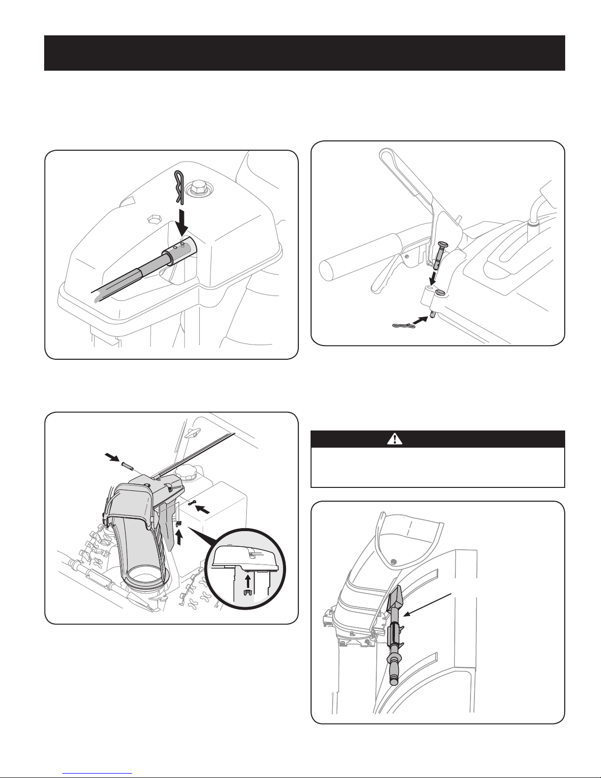
Chute Assembly
1. Remove cotter pin, wing nut and hex screw from chute control
assembly and clevis pin and cotter pin from chute support bracket.
See Figure 3A.
2. Insert round end of the chute control rod (hole pointing upward) as
far as possible into chute control assembly. See Figure 3B.
3. Place chute onto chute base with the chute control rod positioned
under the handle panel. Reinstall the hex bolt previously removed
but do not secure with wing nut at this time. See Figure 4.
Figure 3B
Figure 4
7
Page 8

ASSEMBLY
Front View
Joystick
4. Squeeze the trigger on the joystick, rotate the chute assembly by
hand to face forward. The holes in the chute rotation assembly
should be facing up. See Figure 5.
Figure 5
NOTE: The chute will not rotate without squeezing the trigger on the
joystick.
5. Rotate the joystick to 1 o’clock position (see Figure 6) so the silver
arrow on the pinion gear faces upward (see Figure 7).
Figure 7
NOTE: The pinion gear is located on the front of the unit below the
control panel.
NOTE: The joystick must be angled slightly to the right as shown
Figure 6 and the arrow on the pinion gear at the top to ensure full chute
rotation.
Top
Joystick in the
1 o’clock position.
6. It is important that all cables be routed through the cable guide
and remain positioned on the left side of the chute control rod. See
Figure 8.
7. While supporting the back of the pinion gear insert the hex end of
the chute control rod (hole pointing upward) into the pinion gear.
See Figure 9.
JoystickJoystick
Figure 6
Figure 8
Figure 9
8
Page 9
ASSEMBLY
Chute Clean-out Tool
8. Secure the round end of the chute control rod to the chute control
assembly with the cotter pin removed earlier. See Figure 10.
NOTE: The second hole is used to achieve further engagement of the
chute control rod into the pinion gear if required, refer to “Chute Control
Rod” in the “Adjustment” section.
Figure 10
8. Finish securing chute rotation assembly to chute support bracket with
wing nut, clevis pin and cotter pin removed earlier. See Figure 11.
Shear Pin Storage (optional)
Replacement auger shear pins are included with this manual, or
stowed in the plastic handle panel as shown in Figure 12. Refer to
Augers in the Maintainance Section for more information regarding
shear pin replacement.
Figure 12
Clean-Out Tool
The clean-out tool is mounted to the rear of the auger housing with a
mounting clip and a cable tie at the factory. Cut the cable tie before
operating the snow thrower. See Figure 13.
Figure 11
NOTE: An extension cord may be fastened with a cable tie to the
rear of the auger housing for shipping purposes. Cut the cable tie and
remove it before operating the snow thrower.
CAUTION: Prior to operating your snow thrower, refer to Auger
Control Test in the “Operating” section. Read and follow all
instructions carefully, and perform all adjustments to verify your
snow thrower is operating safely and properly.
WARNING
Never use your hands to clear a clogged chute assembly. Shut
off engine and remain behind handles until all moving parts have
stopped before using the clean-out tool to clear the chute assembly.
Figure 13
9
Page 10
ASSEMBLY
Drift Cutters (If Equipped)
Drift cutters should be used when operating the snow thrower in heavy
drift conditions.
• Onmodelssoequipped,driftcuttersandhardwareareassembled
to the auger housing inverted.
• Removethecarriageboltsandhexnutssecuringthedriftcuttersto
the housing.
• RepositiondriftcutterssotheyfaceforwardasshowninFigure14.
Secure with hardware previously removed.
If your unit is not equipped with drift cutters, you may contact
1-800-4MY-HOME for information regarding price and availability.
Tire Pressure
The tires are over-inflated for shipping purposes. Check the tire
pressure before operating the snow thrower. Refer to the tire side wall
for tire manufacturer’s recommended psi and deflate (or inflate) the
tires as necessary.
WARNING
Under any circumstance do not exceed manufacturer’s recommended psi. Equal tire pressure should be maintained at all times.
Excessive pressure when seating beads may cause tire/rim
assembly to burst with force sufficient to cause serious injury. Refer
to sidewall of tire for recommended pressure.
Figure 14
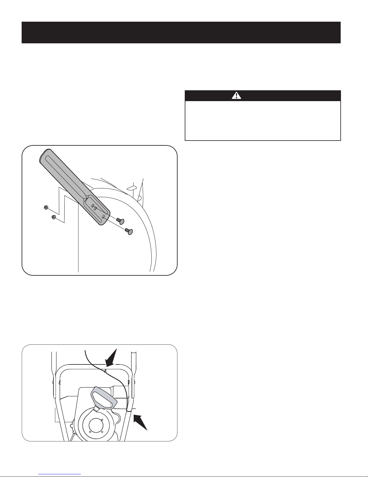
Lamp Wiring Harness (If equipped)
The post on the cable tie attaching the lamp wiring harness to the
lower handle should be plugged into the hole in the lower handle. Pull
the slack portion of the wiring harness through the cable tie to prevent
interference with the recoil starter handle. See Figure 15.
Figure 15
10
Page 11
ASSEMBLY
ADJUSTMENTS
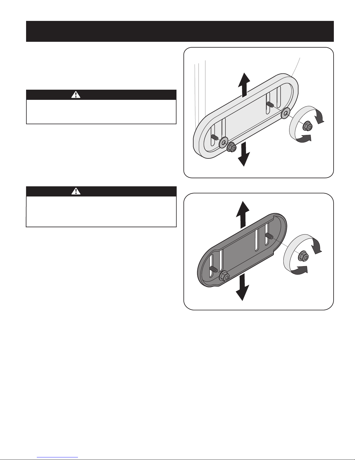
Skid Shoes
The snow thrower skid shoes are adjusted upward at the factory for
shipping purposes. Adjust them downward, if desired, prior to operating the snow thrower.
CAUTION
It is not recommended that you operate this snow thrower on gravel
as it can easily pick up and throw loose gravel, causing personal
injury or damage to the snow thrower and surrounding property.
For close snow removal on a smooth surface, raise skid shoes •
higher on the auger housing.
Use a middle or lower position when the area to be cleared is •
uneven, such as a gravel driveway
NOTE: If you choose to operate the snow thrower on a gravel surface,
keep the skid shoes in position for maximum clearance between the
ground and the shave plate.
CAUTION
Operating a snow thrower quipped with steel skid shoes may result in
damage to natural stone paver surfaces (e.g. sandstone, blue-stone,
limestone). For information on available polymer skid shoes, call
1-800-4MY HOME.
Figure 16 - Polymer Skid Shoe
To adjust the skid shoes:
Loosen the hex nuts , washers (if equipped) and carriage bolts. 1.
Move skid shoes to desired position. See Figure 16 and Figure 17.
Make certain the entire bottom surface of skid shoe is against the 2.
ground to avoid uneven wear on the skid shoes.
Retighten nuts, washers (if equipped) and bolts securely.3.
Figure 17 - Steel Skid Shoe
11
Page 12

ASSEMBLY
Auger Control
WARNING
Prior to operating your snow thrower, carefully read and follow all
instructions below. Perform all adjustments to verify your snow
thrower is operating safely and properly.
Perform the following Auger Control Test before operating your snow
thrower for the first time and at the start of each winter.
Check the adjustment of the auger control as follows:
When the auger control is released and in the disengaged “up” 1.
position, the cable should have very little slack. It should NOT be
tight.
In a well-ventilated area, start the snow thrower engine. Refer to 2.
Starting the Engine in the Operation section.
While standing in the operator’s position (behind the snow 3.
thrower), engage the augers.
Allow the augers to remain engaged for approximately ten (10) 4.
seconds before releasing the auger control. Repeat this several
times.
With the auger control in the disengaged “up” position, walk to the 5.
front of the machine.
Confirm that the augers have completely stopped rotating and 6.
show NO signs of motion. If any auger shows ANY sign of
rotating, immediately return to the operator’s position and shut off
the engine. Wait for ALL moving parts to stop before adjusting the
auger control.
To readjust the control cable, loosen the upper hex bolt on the 7.
auger cable bracket. See Figure 18.
Position the bracket upward to provide more slack (or downward 8.
to increase cable tension).
Retighten the upper hex bolt.9.
Repeat Auger Control Test to verify proper adjustment has been 10.
achieved.
Figure 18
12
Page 13

OPERATION
Drive Control
Chute Assembly
Gas Cap
Headlight
Shift Lever
Four-Way Chute Control™ (Joystick)
Auger Control
Clean Out
To ol
Augers
Skid Shoe
Wheel Steering Control
Heated Grips
Drift Cutters
Oil Drain
Electric Starter Outlet
Primer
Throttle
Control
Choke
Control
Electric
Starter
Button
Recoil Starter
Handle
Key
Oil Fill
Now that you have set up your snow thrower, it’s important to become
acquainted with its controls and features. Refer to Figure 19.
SHIFT LEVER
The shift lever is located on the right side of the handle panel.
Place the shift lever into any of eight positions to control the
direction of travel and ground speed.
Forward
Your snow thrower has six forward (F) speeds. Position one (1) is
the slowest and position six (6) is the fastest.
Reverse
Your snow thrower has two reverse (R) speeds. One (1) is the
slower and two (2) is the faster.
DRIFT CUTTERS (if so equipped)
The drift cutters are designed for use in deep snow. Their use is
optional for normal snow conditions. Maneuver the snow thrower so
that the cutters penetrate a high standing snow drift to assist snow
falling into the augers for throwing.
SKID SHOES
Position the skid shoes based on surface conditions. Adjust upward
for hard-packed snow. Adjust downward when operating on gravel or
crushed rock surfaces.
Figure 19
KEY
The key is a safety device. It must be fully inserted in order for the
engine to start. Remove the key when the snow thrower is not in use.
NOTE: Do not turn the key in an attempt to start the engine. Doing so
may cause it to break.
CHOKE CONTROL
The choke control is found on the rear of the engine and is activated
by turning the rotary choke knob to the CHOKE position. Activating
the choke control closes the choke plate on the carburetor and aids in
starting the engine.
PRIMER
Depressing the primer forces fuel directly into the engine’s carburetor
to aid in cold-weather starting.
OIL FILL
Engine oil level can be checked and oil added through the oil fill.
GAS CAP
Unthread the gas cap to add gasoline to the fuel tank.
13
Page 14
OPERATION
THROTTLE CONTROL
The throttle control is located on the rear of the engine. It regulates the
speed of the engine and will shut off the engine when moved into the
STOP position.
RECOIL STARTER HANDLE
This handle is used to manually start the engine.
ELECTRIC STARTER BUTTON
Pressing the electric starter button engages the engine’s electric
starter when plugged into a 120V power source.
ELECTRIC STARTER OUTLET
Requires the use of a three-prong outdoor extension cord (included)
and a 120V power source/wall outlet.
HEATED GRIPS (if so equipped)
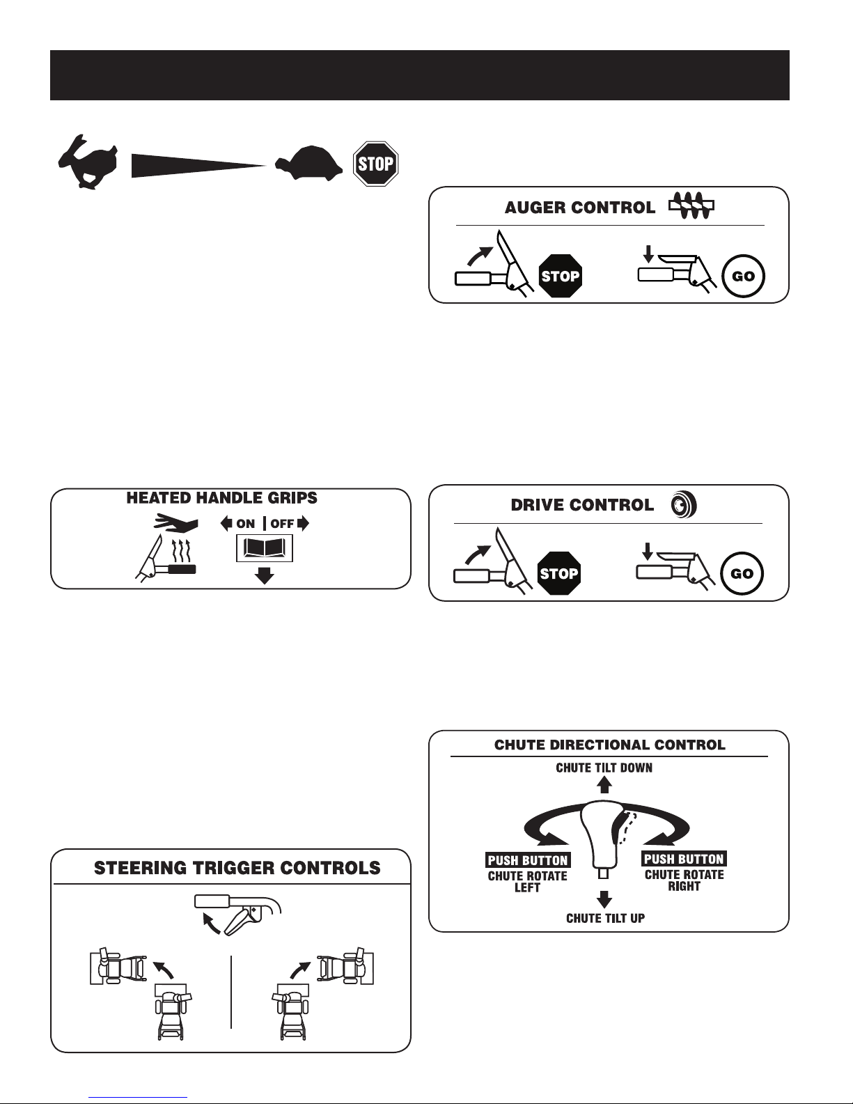
AUGER CONTROL
The auger control is located on the left handle. Squeeze the control
grip against the handle to engage the auger and start snow throwing
action. Release to stop.
DRIVE CONTROL/ AUGER CONTROL LOCK
The drive control is located on the right handle. Squeeze the control
grip against the handle to engage the wheel drive. Release to stop.
The drive control also locks the auger control so you can operate
the chute directional control without interrupting the snow throwing
process. If the auger control is engaged simultaneously with the drive
control, the operator can release the auger control (on the left handle)
and the augers will remain engaged. Release both controls to stop the
augers and wheel drive.
This switch is located on the rear of the snow thrower dash panel. To
activate the heated handles, toggle the switch to the “ON” position to
generate heat within the handle grips. Toggle the switch to the “OFF”
position after using the snow thrower.
HEADLIGHTS (if so equipped)
The headlight is on whenever the engine is running.
WHEEL STEERING CONTROLS
The left and right wheel steering controls are located on the underside
of the handles. Squeeze the right control to turn right; squeeze the left
control to turn left.
NOTE: Operate the snow thrower in open areas until you are familiar
with these controls.
NOTE: Always release the drive control before changing speeds.
Failure to do so will result in increased wear on your machine’s drive
system.
FOUR-WAY CHUTE CONTROL™
The four-way chute control™ (Joystick) is located on the left side of the
handle panel.
To change the direction in which snow is thrown, squeeze the •
button on the chute control lever and pivot the chute control lever
to the right or to the left.
To change the angle/distance which snow is thrown, pivot the •
chute control lever forward to tilt the chute down and backward to
tilt the chute up.
14
Page 15

OPERATION
CLEAN-OUT TOOL
WARNING
Never use your hands to clear a clogged chute assembly. Shut
off engine and remain behind handles until all moving parts have
stopped before unclogging.
The chute clean-out tool is conveniently fastened to the rear of the
auger housing with a mounting clip. Should snow and ice become
lodged in the chute assembly during operation, proceed as follows to
safely clean the chute assembly and chute opening:
Release both the Auger Control and the Drive Control.1.
Stop the engine by removing the ignition key. 2.
Remove the clean-out tool from the clip which secures it to the 3.
rear of the auger housing.
Use the shovel-shaped end of the clean-out tool to dislodge and 4.
scoop any snow and ice which has formed in and near the chute
assembly.
Refasten the clean-out tool to the mounting clip on the rear of 5.
the auger housing, reinsert the ignition key and start the snow
thrower’s engine.
While standing in the operator’s position (behind the snow 6.
thrower), engage the auger control for a few seconds to clear any
remaining snow and ice from the chute assembly.
Refuel in a well-ventilated area with the engine stopped. Do not •
smoke or allow flames or sparks in the area where the engine is
refueled or where gasoline is stored.
Do not overfill the fuel tank. After refueling, make sure the tank •
cap is closed properly and securely.
Be careful not to spill fuel when refueling. Spilled fuel or fuel vapor •
may ignite. If any fuel is spilled, make sure the area is dry before
starting the engine.
Avoid repeated or prolonged contact with skin or breathing of •
vapor.
WARNING
Use extreme care when handling gasoline. Gasoline is extremely
flammable and the vapors are explosive. Never fuel the machine
indoors or while the engine is hot or running. Extinguish cigarettes,
cigars, pipes and other sources of ignition.
Clean around fuel fill before removing cap to fuel.1.
A fuel level indicator is located in the fuel tank. See Figure 19 2.
inset. Be careful not to overfill. Fill tank until fuel reaches the fuel
level indicator to allow space for fuel expansion.
STARTING THE ENGINE
WARNING
Always keep hands and feet clear of moving parts. Do not use a
pressurized starting fluid. Vapors are flammable.
BEFORE STARTING ENGINE
WARNING
Read, understand, and follow all instructions and warnings on the
machine and in this manual before operating.
Oil
The unit was shipped with oil in the engine. Check oil level before
each operation to ensure adequate oil in the engine. For further
instructions, refer to the steps on page 18.
NOTE: Be sure to check the engine on a level surface with the engine
stopped.
Remove the oil filler cap/dipstick and wipe the dipstick clean.1.
Insert the cap/dipstick into the oil filler neck, and tighten the cap 2.
until seated.
Remove the oil filler cap/dipstick. If level is low, slowly add oil until 3.
oil level registers between high (H) and low (L)..
NOTE: Do not overfill. Overfilling with oil may result in engine smoking,
hard starting or spark plug fouling.
Replace and tighten cap/dipstick firmly before starting engine.4.
Gasoline
Use automotive gasoline (unleaded or low leaded to minimize combustion chamber deposits) with a minimum of 87 octane. Gasoline with
up to 10% ethanol or 15% MTBE (Methyl Tertiary Butyl Ether) can be
used. Never use an oil/gasoline mixture or dirty gasoline. Avoid getting
dirt, dust, or water in the fuel tank. DO NOT use E85 gasoline.
NOTE: Allow the engine to warm up for a few minutes after starting.
The engine will not develop full power until it reaches operating
temperatures.
Make certain both the auger control and drive control are in the 1.
disengaged (released) position.
Insert key into slot. Make sure it snaps into place. Do not attempt 2.
to turn the key.
NOTE: The engine cannot start without the key fully inserted into the
ignition switch.
Electric Starter (if so equipped)
WARNING
The optional electric starter is equipped with a grounded three-wire
power cord and plug, and is designed to operate on 120 volt AC
household current. It must be used with a properly grounded threeprong receptacle at all times to avoid the possibility of electric shock.
Follow all instructions carefully prior to operating the electric starter.
DO NOT use electric starter in the rain.
Determine that your home’s wiring is a three-wire grounded system.
Ask a licensed electrician if you are not certain.
If you have a grounded three-prong receptacle, proceed as follows.
If you do not have the proper house wiring, DO NOT use the electric
starter under any conditions.
Plug the extension cord into the outlet located on the engine’s 1.
surface. Plug the other end of extension cord into a three-prong
120-volt, grounded, AC outlet in a well-ventilated area.
15
Page 16

OPERATION
Move throttle control to FAST (rabbit)2. position.
Move choke to the CHOKE3.
engine is warm, place choke in RUN position.
Push primer three (3) times, making sure to cover vent hole in 4.
primer bulb when pushing. If engine is warm, push primer only
once. Always cover vent hole when pushing. Cool weather may
require priming to be repeated.
Push starter button to start engine. 5. Once the engine starts,
immediately release starter button. Do not run starter more than
10 times at intervals of 5 seconds on/5 seconds off. Electric
starter is equipped with thermal overload protection; system will
temporarily shut-down to allow starter to cool if electric starter
becomes overloaded.
As the engine warms, slowly rotate the choke control to RUN 6.
position. If the engine falters, restart engine and run with choke
at half-choke position for a short period of time, and then slowly
rotate the choke into RUN position.
After engine is running, disconnect power cord from electric 7.
starter. When disconnecting, always unplug the end at the wall
outlet before unplugging the opposite end from the engine.
position (cold engine start). If
CAUTION
Do not pull the starter handle while the engine running.
Recoil Starter
Move throttle control to FAST (rabbit)1. position.
Move choke to the CHOKE2.
engine is warm, place choke in RUN position.
Push primer three (3) times, making sure to cover vent hole when 3.
pushing. If engine is warm, push primer only once. Always cover
vent hole when pushing. Cool weather may require priming to be
repeated.
Pull gently on the starter handle until it begins to resist, then 4.
pull quickly and forcefully to overcome the compression. Engine
should start. Do not release the handle and allow it to snap back.
Return rope SLOWLY to original position. If required, repeat this
step.
As the engine warms, slowly rotate the choke control to RUN 5.
position. If the engine falters, restart engine and run with choke
at half-choke position for a short period of time, and then slowly
rotate the choke into RUN position.
position (cold engine start). If
STOPPING THE ENGINE
After you have finished snow-throwing, run engine for a few minutes
before stopping to help dry off any moisture on the engine.
Move throttle control to OFF position.1.
Remove the key. Removing the key will reduce the possibility of 2.
unauthorized starting of the engine while equipment is not in use.
Keep the key in a safe place. The engine cannot start without the
key.
Wipe any moisture away from the controls on the engine.3.
TO ENGAGE DRIVE
With the throttle control in the Fast (rabbit) position, move shift 1.
lever into one of the six forward (F) positions or two reverse (R)
positions. Select a speed appropriate for the snow conditions and
a pace you’re comfortable with.
NOTE: When selecting a Drive Speed, use the slower speeds until
you are comfortable and familiar with the operation of the snow
thrower.
2. Squeeze the drive control against the handle and the snow
thrower will move. Release it and drive motion will stop.
TO ENGAGE AUGERS
To engage augers and start snow throwing, squeeze the left hand 1.
auger control against the left handle. Release to stop augers.
While the auger control is engaged, squeeze the drive control 2.
to move, release to stop. Do not shift speeds while the drive is
engaged.
NOTE: This drive lever also locks auger control so you can turn the
chute control without interrupting the snow throwing process.
Release the auger control; the interlock mechanism should keep 3.
the auger control engaged until the drive control is released.
Release the drive control to stop both the augers and the wheel 4.
drive. To stop the auger, both levers must be released.
WARNING
To avoid unsupervised engine operation, never leave the machine
unattended with the engine running. Turn the engine off after use and
remove key.
16
Page 17

OPERATION
REPLACING SHEAR PINS
The augers are secured to the spiral shaft with shear pins and cotter
pins. If the augers should strike a foreign object or ice jam, the snow
thrower is designed so that the pins may shear. If the augers will not
turn, check to see if the pins have sheared. See Figure 20.
CAUTION
NEVER replace the auger shear pins with anything other than Sears
SKU# 88389/OEM Part No. 738-04124A replacement shear pins.
Any damage to the auger gearbox or other components as a result of
failing to do so will NOT be covered by your snow thrower’s warranty.
WARNING
Always turn off the snow thrower’s engine and remove the key prior to
replacing shear pins.
Figure 20
17
Page 18

SERVICE AND MAINTENANCE
MAINTENANCE SCHEDULE
WARNING
Before performing any type of maintenance/service, disengage all
controls and stop the engine. Wait until all moving parts have come to
a complete stop. Disconnect spark plug wire and ground it against the
engine to prevent unintended starting. Always wear safety glasses during
operation or while performing any adjustments or repairs.
Interval Item Service Service Log
Each Use and every 5
hours
1st 5 hours Engine oil1. Change1.
Annually or 25 hours Spark plug1.
Annually or 50 hours Engine oil1. Change1.
Annually or 100 hours Spark plug1. Change1.
Before Storage Fuel system1. Run engine until it stops from lack 1.
Engine oil level1.
Loose or missing hardware2.
Unit and engine.3.
Control linkages and pivots2.
Wheels3.
Gear shaft and Auger shaft4.
Follow the maintenance schedule given below. This chart describes
service guidelines only. Use the Service Log column to keep track of
completed maintenance tasks. To locate the nearest Sears Service
Center or to schedule service, simply contact Sears at
1-800-4-MY-HOME®.
Check1.
Tighten or replace2.
Clean3.
Check1.
Lube with light oil2.
Lube with multipurpose auto grease3.
Lube with light oil4.
of fuel
ENGINE MAINTENANCE
Checking Engine Oil
WARNING
Before lubricating, repairing, or inspecting, disengage all controls
and stop engine. Wait until all moving parts have come to a complete
stop.
NOTE: Check the oil level before each use to be sure correct oil level
is maintained.
When adding oil to the engine, refer to viscosity chart below. Engine
oil capacity is 1100 ml (approx. 37 oz.). Do not over-fill. Use a 4-stroke,
or an equivalent high detergent, premium quality motor oil certified
to meet or exceed U.S. automobile manufacturer’s requirements for
service classification SG, SF. Motor oils classified SG, SF will show
this designation on the container.
Remove the oil filler cap/dipstick and wipe the dipstick clean.1.
Insert the cap/dipstick into the oil filler neck, and tighten the cap 2.
until seated.
Remove the oil filler cap/dipstick. If level is low, slowly add oil until 3.
oil level registers between high (H) and low (L). See Figure 21.
Replace and tighten cap/dipstick firmly before starting engine.4.
Changing Engine Oil
Oil Fill Dipstick
Fill
between
high
and low
marks
Figure 21
Place suitable oil collection container under oil drain plug. 2.
Remove oil drain plug. See Figure 22 on next page.3.
Tip engine to drain oil into the container. Used oil must be 4.
disposed of at a proper collection center.
NOTE: Change the engine oil after the first 5 hours of operation and
once a season or every 50 hours thereafter.
Drain fuel from tank by running engine until the fuel tank is empty. 1.
Be sure fuel fill cap is secure.
CAUTION
Used oil is a hazardous waste product. Dispose of used oil properly.
Do not discard with household waste. Check with your local authorities or Sears Service Center for safe disposal/recycling facilities.
18
Page 19

SERVICE AND MAINTENANCE
Oil Drain
Plug
.02-.03 in.
(0.60-0.80 mm)
Electrode
Spark Plug
Spark Plug Boot
Reinstall the drain plug and tighten it securely. 5.
Refill with the recommended oil and check the oil level. 6. See
Recommended Oil Usage chart. The engine’s oil capacity is 37
ounces.
Synthetic
0W-30
5W-30
-40º
0º 20º 40º-20º
-30º -20º -10º 0º
CAUTION
DO NOT use nondetergent oil or 2-stroke engine oil. It could shorten
the engine’s service life.
Reinstall the oil filler cap/dipstick securely.7.
CAUTION
Thoroughly wash your hands with soap and water as soon as
possible after handling used oil.
Checking Spark Plug
WARNING
DO NOT check for spark with spark plug removed. DO NOT crank
engine with spark plug removed.
WARNING
If the engine has been running, the muffler will be very hot. Be careful
not to touch the muffler.
Figure 22
NOTE: Check the spark plug once a season or every 25 hours of
operation. Change the spark plug once a season or every 100 hours.
To ensure proper engine operation, the spark plug must be properly
gapped and free of deposits.
Remove the spark plug boot and use a spark plug wrench to 1.
remove the plug. See Figure 23.
Visually inspect the spark plug. Discard the spark plug if there is 2.
apparent wear, or if the insulator is cracked or chipped. Clean the
spark plug with a wire brush if it is to be reused.
Measure the plug gap with a feeler gauge. Correct as necessary 3.
by bending side electrode. See Figure 24. The gap should be set
to .02-.03 inches (0.60-0.80 mm).
Check that the spark plug washer is in good condition and thread 4.
the spark plug in by hand to prevent cross-threading.
After the spark plug is seated, tighten with a spark plug wrench to 5.
compress the washer.
NOTE: When installing a new spark plug, tighten 1⁄2-turn after the
spark plug seats to compress the washer. When reinstalling a used
spark plug, tighten 1⁄8- to 1⁄4-turn after the spark plug seats to
compress the washer.
Figure 23
Figure 24
19
Page 20

SERVICE AND MAINTENANCE
CAUTION
The spark plug must be tightened securely. A loose spark plug can
become very hot and can damage the engine.
LUBRICATION
Gear Shaft
The gear (hex) shaft should be lubricated at least once a season or
after every 25 hours of operation.
To prevent spillage, remove all fuel from tank by running engine 1.
until it stops.
Carefully pivot the snow thrower up and forward so that it rests on 2.
the auger housing.
Remove the lower frame cover from the underside of the snow 3.
thrower by removing the self-tapping screws which secure it.
Apply a light coating of engine oil (or 3-in-1 oil) to the hex shaft. 4.
See Figure 25.
NOTE: When lubricating the hex shaft, be careful not to get any oil on
the aluminum drive plate or rubber friction wheel. Doing so will hinder
the snow thrower’s drive system. Wipe off any excess or spilled oil.
Wheels
At least once a season, remove both wheels. Clean and coat the axles
with a multipurpose automotive grease before reinstalling wheels.
Auger Shaft
At least once a season, remove the shear pins on auger shaft. Spray
lubricant inside shaft, and around the spacers and flange bearings
found at either end of the shaft. See Figure 26.
SHAVE PLATE AND SKID SHOES
The shave plate and skid shoes on the bottom of the snow thrower are
subject to wear. They should be checked periodically and replaced
when necessary.
NOTE: The skid shoes on this machine have two wear edges. When
one side wears out, they can be rotated 180° to use the other edge.
To remove skid shoes:
Remove the two carriage bolts, washers (if equipped), and hex 1.
flange nuts that secure each skid shoe to the snow thrower.
Reassemble new skid shoes with the four carriage bolts (two on 2.
each side), washers, and hex flange nuts. Refer to Figure 27.
To remove shave plate:
Remove the carriage bolts and hex nuts which attach it to the 1.
snow thrower housing.
Reassemble new shave plate, making sure heads of carriage 2.
bolts are to the inside of housing. Tighten securely. See Figure 27.
Figure 25
Figure 26
Figure 27
20
Page 21

SERVICE AND MAINTENANCE
ADJUSTMENTS
Shift Cable
If the full range of speeds (forward and reverse) cannot be achieved,
refer to the figure to the right and adjust the shift cable as follows:
Place the shift lever in the 1. fastest forward speed position (F6).
Loosen the hex nut on the shift cable index bracket. See Figure 2.
28.
Pivot the bracket downward to take up slack in the cable. 3.
Retighten the hex nut.4.
If further adjustment is necessary move the shift cable to one of 5.
the alternate holes in the shift cable index bracket.
Drive Control
When the drive control is released and in the disengaged “up” position,
the cable should have very little slack. It should NOT be tight. Also,
if there is excessive slack in the drive cable or if the unit experiences
intermittent drive while using, the cable may need to be adjusted.
Check the adjustment of the drive control as follows:
With the drive control released, push the snow thrower gently 1.
forward. The unit should roll freely.
Engage the drive control and gently attempt to push the snow 2.
thrower forward. The wheels should not turn. The unit should not
roll freely.
With the drive control released, move the shift lever back and 3.
forth between the R2 position and the F6 position several times.
There should be no resistance in the shift lever.
If any of the above tests failed, the drive cable is in need of 4.
adjustment. Proceed as follows:
Shut off the engine as instructed in the Operation section.5.
Loosen the lower hex bolt on the drive cable bracket. See Figure 6.
29.
Position the bracket upward to provide more slack (or downward 7.
to increase cable tension).
Retighten the lower hex bolt.8.
Repeat Drive Control Test, steps 1-4 to verify proper adjustment 9.
has been achieved.
Figure 28
Figure 29
Chute Control Rod
To achieve more chute control rod engagement in the input shaft under
the handle panel, the chute control rod will have to be adjusted. Refer
to Figure 30.
To adjust this rod, proceed as follows:
Remove the cotter pin from the hole closest to the chute control 1.
head on the chute control input.
Pull out the chute control rod until the hole in it lines up with the 2.
other hole in the chute control input.
Reinsert the cotter pin through this hole and the chute control rod. 3.
Figure 30
21
Page 22

SERVICE AND MAINTENANCE
B
A
Auger Control
Refer to the Assembly section for instructions on adjusting the auger
control cable.
Skid Shoes
Refer to the Assembly section for instructions on adjusting the skid
shoes.
BELT REPLACEMENT
Auger Belt
To remove and replace your snow thrower’s auger belt, proceed as
follows:
To prevent spillage, remove all fuel from tank by running engine 1.
until it stops.
Remove the plastic belt cover on the front of the engine by remov-2.
ing the two self-tapping screws. See Figure 31.
Figure 32
Figure 31
Roll the auger belt off the engine pulley. See Figure 32.3.
Carefully pivot the snow thrower up and forward so that it rests on 4.
the auger housing.
Remove the frame cover from the underside of the snow thrower 5.
by removing the self-tapping screws which secure it. See Figure
33.
Remove the belt as follows. Refer to Figure 34.6.
a. Loosen and remove the shoulder screw which acts as a belt
keeper.
b. Unhook the auger brake bracket spring from the frame.
Figure 33
Figure 34
22
Page 23

SERVICE AND MAINTENANCE
Stop Bolt
7. Remove the belt from around the auger pulley, and slip the belt
between the support bracket and the auger pulley. See Figure 35.
8. Reassemble auger belt by following these instructions in opposite
order and manner of removal.
9. Perform the Auger Control test outlined in the Assembly section
of this manual.
NOTE: Do NOT forget to reinstall the shoulder screw and reconnect
the spring to the frame after installing a replacement auger belt.
Drive Belt
To remove and replace your snow thrower’s drive belt, proceed as
follows:
To prevent spillage, remove all fuel from tank by running engine 1.
until it stops.
Remove the plastic belt cover on the front of the engine by remov-2.
ing the two self-tapping screws. See Figure 31 on previous page.
Remove the belt from engine pulley as follows. Refer to Figure 36.3.
a. Roll the auger belt off the engine pulley.
b. Use a wrench to pivot the idler pulley toward the right.
c. Lift the drive belt off engine pulley.
4. Carefully pivot the snow thrower up and forward so that it rests on
the auger housing.
5. Remove the frame cover from the underside of the snow thrower
by removing the self-tapping screws which secure it. Refer to
Figure 33.
6. Back out the stop bolt to increase the clearance between the
friction wheel disc and friction wheel. See Figure 37.
7. Slip the drive belt off the friction wheel disc and between friction
wheel and friction wheel disc. See Figure 37.
8. Reassemble drive belt by following these instructions in opposite
order and manner of removal. Be sure to reinstall the stop bolt.
FRICTION WHEEL INSPECTION
If the snow thrower fails to drive with the drive control engaged, and
performing the Drive Control Cable Adjustment fails to correct the
problem, the friction wheel may need to be replaced. Examine the
friction wheel for signs of wear or cracking and replace if necessary.
Figure 35
C
A
B
Figure 36
NOTE: Several components must be removed and special tools are
required in order to replace this snow thrower’s friction wheel rubber.
If your friction wheel rubber needs to be replaced, contact the nearest
Sears Parts & Repair Center.
Figure 37
23
Page 24

OFF-SEASON STORAGE
If the snowthrower will not be used for 30 days or longer, or if it is the end of the snow season when the last possiblity of snow is gone, the equipment needs to be stored properly. Follow storage instructions below to ensure top performance from the snow thrower for many more years.
PREPARING ENGINE
Engines stored over 90 days need to be drained of fuel to prevent
deterioration and gum from forming in fuel system or on essential
carburetor parts. If the gasoline in your engine deteriorates during
storage, you may need to have the carburetor, and other fuel system
components, serviced or replaced.
Remove all fuel from tank by running engine until it stops from 1.
lack of fuel.
Change the oil.2.
Remove the spark plug and pour approximately a 3. 1 ounce (30 ml)
of clean engine oil into the cylinder. Replace spark plug and crank
it slowly to distribute oil.
Clean debris from around the engine and the muffler. Touch up 4.
any damaged paint, and coat other areas that may rust with a light
film of oil.
Store in a clean, dry and well ventilated area away from any ap-5.
pliance that operates with a flame or pilot light, such as a furnace,
water heater, or clothes dryer. Also avoid any area with a spark
producing electric motor, or where power tools are operated.
WARNING
Never store snow thrower with fuel in tank indoors or in poorly
ventilated areas, where fuel fumes may reach an open flame, spark
or pilot light as on a furnace, water heater, clothes dryer or gas
appliance.
PREPARING SNOWTHROWER
When storing any type of power equipment in a poorly ventilated •
or metal storage shed, care should be taken to rustproof the
equipment. Using a light oil or silicone, coat the equipment,
especially any chains, springs, bearings and cables.
Clean snowthrower thoroughly.•
Lubricate as instructed in the Maintenance section of this manual.•
Refer to engine manual for correct engine storage instructions.•
Store the snow thrower in a clean, dry area.•
If possible, also avoid storage areas with high humidity, because 6.
that promotes rust and corrosion.
Keep the engine level in storage. Tilting can cause fuel or oil 7.
leakage.
24
Page 25

Problem Cause Remedy
Engine fails to start Choke not in CHOKE position.1.
TROUBLESHOOTING
Spark plug wire disconnected.2.
Faulty spark plug.3.
Fuel tank empty or stale fuel.4.
Engine not primed.5.
Key not in ignition on engine.6.
Extension cord not connected (when 7.
using electric start button, on models so
equipped)
Move choke to CHOKE position.1.
Connect wire to spark plug.2.
Fill tank with clean, fresh gasoline.3.
Prime engine as instructed in the Operation section.4.
Clean, adjust gap, or replace.5.
Insert key fully into the switch.6.
Connect one end of the extension cord to the electric 7.
starter outlet and the other end to a three-prong
120-volt, grounded, AC outlet.
Engine running erratically/
inconsistent RPM (hunting or
surging)
Excessive vibration Loose parts or damaged auger.1. Stop engine immediately and disconnect spark plug 1.
Loss of power Spark plug wire loose.1.
Unit fails to propel itself Drive control cable in need of adjustment.1.
Unit fails to discharge snow Chute assembly clogged. 1.
Engine running on CHOKE.1.
Stale fuel.2.
Water or dirt in fuel system.3.
Engine over-governed4.
Gas cap vent hole plugged.2.
Drive belt loose or damaged.2.
Friction wheel worn.3.
Foreign object lodged in auger. 2.
Auger control cable in need of adjustment.3.
Auger belt loose or damaged.4.
Shear pin(s) sheared.5.
Move choke lever to RUN position.1.
Fill tank with clean, fresh gasoline.2.
Drain fuel tank. Refill with fresh fuel.3.
Contact an authorized Service Center.4.
wire. Tighten all bolts and nuts. If vibration continues,
have unit serviced by an authorized Service Center.
Connect and tighten spark plug wire.1.
Remove ice and snow from gas cap. Be certain vent 2.
hole is clear.
Adjust drive control cable. Refer to Maintenance & 1.
Adjustments section.
Replace drive belt. Refer to Service section2.
Replace friction wheel. Refer to Service section.3.
Stop engine immediately and disconnect spark plug 1.
wire. Clean chute assembly and inside of auger
housing with clean-out tool or a stick.
Stop engine immediately and disconnect spark plug 2.
wire. Remove object from auger with clean-out tool
or a stick.
Refer to Auger Control Test. 3.
Refer to Maintenance & Adjustments section.4.
Replace with new shear pin(s).5.
Chute fails to easily rotate 180
degrees
Chute assembled incorrectly.1. Unassemble chute control and reassemble as 1.
directed in the Assembly & Set-up section.
25
Page 26

15
16
17
34
35
31
6
32 71
28
39
68
1
10
37
1
84
17
39
1
7
17
16
14
70
4
68
1
18B
12
25
23
12
70
23
9
24
44
22
25
8
40
5
41
1
A
A
45
669
38
27
26
46
43
26 27
42
61
36
62
60
51
55
52
58
53
50
49
48
47
67
59
20
54
19
64
64
72
65
66
63
56
57
56
28
18A
14
16
21
*
*
43
42
42A
42E
42B
42C
42F
42D
42H
42G
43A
77
43B
43
71
74
76
73
39
13
82
75
81
80
30
1
83
35
79
2
3
85
86
*
Refer to wheel chart./
*
Consultez le tableau des roues.
87
86
85
26
Page 27

REF PART
NO. NO.
N° DE N° DE
RÉF PIÈCE DESCRIPTION DESCRIPTION
1 710-1652 Hex Wash Hd TT Scr. 1/4-20 x .625 Vis taraudée 1/4-20 x 0,625
2 731-06401 Belt Cover (w/277 cc - 357 cc engines) Couvre-courroie (avec 277 cc - 357 cc moteurs)
731-05353 Belt Cover (w/208 cc engine) Couvre-courroie (avec 208 cc moteur)
3 732-04677 Cable Control Wire (w/277 cc - 357 cc engines) Fil de commande de la câble (avec 277 cc - 357 cc moteurs)
4 711-1268B Drive Shaft Actuator R égulateur
5 946-04229B Drive Clutch Cable 44.83” Lg. Câble de l’entraînement 44,83 po de lg.
6 732-04345 Extension Spring .5 OD x 1.71 Lg. Ressort d’extension 0,5 DE x 1,71 po de lg.
7 790-00207C Guide Bracket - Drive Cable Support - câble de l’entraînement
8 684-04156A Shift Rod Ass’y Tige de changement de la vitesses
9 750-04474 Axle Support Tube Tuyau de support de l’essieu
10 914-0126 #9 HI-Pro Key 3/16 x 3/4 Dia HT Clavette HI-Pro no. 9 - 3/16 x 3/4 dia.
12 917-04210 Gear, 56T Engrenage 56 dents
13 712-04063 Flange Lock-Nut 5/16-18 Gr. F Nylon Contre-écrou à embase 5/16-18Qual. F nylon
14 941-0245 Hex. Flange Bearing.751” ID Roulement à bride à six pans 0,751 DI
15 790-00206A-0637 Guide Bracket - Auger Cable Support - Câble de tarière
16 756-0625 Cable Guide Roller Guide du câble
17 738-0924A Hex Shld.Scr.1/4-28 x .375 Vis à épaulement 1/4-28 x 0,375
18A 618-04288 Dogg Assembly - LH CG - cliquet
18B 618-04287 Dogg Assembly - RH CD - cliquet
19 926-04012 Push Nut Écrou à enfoncer
20 750-04477A Spacer .340 x .750 x .360” Lg. Entretoise 0,340 x 0,750 x 0,360 po de lg.
21 736-0329 L-Wash 1/4 ID Rondelle frein 1/4 DI
22 732-04311 Torsion Spring .750 ID x .968” Lg. Ressort de torsion 0,750 DI x 0,968 po de lg.
23 731-05297 Spacer Entretoise
24 916-0104 Retaining Ring Anneau de retenue
25 736-0188 Flat Washer .760 ID x 1.49 OD Rondelle plate 0,760 DI x 1,49 DE
26 736-0626 Flat Washer .580 x 1.125 x .080 Rondelle plate 0,580 x 1,125 x 0,080
27 741-04076 Ball Bearing Roulement à billes
28 938-04180 Axle Essieu
30 710-0654A Hex Wash HD Tap Scr 3/8-16 x .88 Vis autotaraudee 3/8-16 x 0,88
31 710-0788 Hex Bolt 1/4-20 x 1.00 Vis à tête hex. 1/4-20 x 1,00
32 790-00185 Shaft R etainer - LH Retenue d’arbre CG
34 736-0242 Cupped Washer .345 ID x .88 OD x .060 Rondelle creuse 0,345 DI x 0,88 DE x 0,060
35 738-04439 Shoulder Screw .50 x .145: 5/16-24 Vis épaulement 0,50 x 0,145: 5/16-24
36 684-04154B Friction Wheel Support Brkt Ass’y Suppor t de la roue du friction
37 790-00096-0637 Auger Cable Guide Bracket Support, guide de la câble de la tarière
38 748-0190 Spacer .513 ID x 1.0 Entretoise 0,513 DI x 1,0
39 738-04184A Shoulder Screw .373 x .105:TT 1/4-20 Vis à épaulement 0,373 x 0,105:1/4-20
40 790-00316-0637 Frame Cover Couvercle
41 656-04055 Friction Wheel Disc Assembly Disque de roue du friction
42 918-04322A Drive Shaft Assembly (w/o Friction Wheel Ass’y) Arbre d’entraînement (sans ensemble de la roue frottement)
42A 711-04416A Hex Drive Shaft (500) Arbre d’entraînement (500)
42B 918-04284 Planetary Carrier Ass’y Porte-roue
42C 717-1209A Gear 12T Engrenage 12 dents
42D 936-0502 Flat Washer .58 x 1.12 x .02 Rondelle plate 0,58 x 1,12 x 0,02
42E 936-0336 Flat Washer 5/8 ID x 1.0 OD Rondelle plate 5/8 DI x 1,0 DE
42F 717-1210A Gear 18T Engrenage 18 dents
42G 918-04285 R ing Planetary Gear Ass’y (500) Ensemble de l’engrenage (500)
42H 716-0194 Retaining Ring 1.56 diam. Bague de retenue 1,56 diam.
43 684-04159 Friction Wheel Assembly Ensemble de la roue de frottement
43A 935-04054 Friction Wheel Rubber Roue du friction en caoutchouc
43B 790-00174 Friction Plate Plaque du friction
44 716-0136 Retainer Ring Bague de retenue
45 726-0221 Cap Speed Nut 1/4 Rod Chapeau à enfoncer
46 790-00183B-0637 Wheel Drive Frame Châssis de l’entraînement de roue
47 756-04109 Auger Pulley Poulie de la tarière
48 736-0505 Flat Washer .34 x 1.50 x .150 Rondelle plate 0,34 x 1,50 x 0,150
49 710-1245B Hex Bolt 5/16-24 x 0.875 Boulon hex. 5/16-24 x 0,875
50 936-0119 L-Wash 5/16 ID Rondelle frein 5/16 DI
51 790-00230 Bearing Sleeve Roulement
52 941-0919 Ball Bearing 20 x 47 x 14:6204:DS Roulement à billes 20 x 47 x 14:6204:DS
53 750-04571 Spacer Entretoise
54 732-04308A Torsion Spring .850 ID x .354” Lg. Ressort de torsion 0,850 DI x 0,354 po de lg.
55 710-0672 Hex HD. Cap Scr. 5/16-24 x 1.25 Lg. Vis à tête hexagonal 5/16-24 x 1,25 po de lg
56 756-04252 Pulley Half Poulie, demi
57 754-04260 Belt 3/8 x 34.13” Lg.(w/208 cc engine) Courroie trapézoïdale 3/8 x 34,13 po de lg. (avec 208 cc moteurs)
954-04201A Belt 3/8 x 35.68” Lg.(w/277cc - 357cc engines) Courroie trapézoïdale 3/8 x 35,68 po de lg.(avec 277cc - 357cc moteurs)
58 710-0809 Hex Bolt 1/4-20 x 1.25 Boulon hex. 1/4-20 x 1,25
59 790-00208C Wheel Drive Idler Bracket Support
60 748-04112B Shoulder Spacer Entretoise épaulée
61 932-0264 Extension Spring 3/8 OD x 2.50 Ressort d’extension 3/8 DE x 2,50
62 712-0417A Jam L-Nut 5/8-18 Gr. 5 Nylon Écrou de blocage 5/8-18 Qual. 5 Nylon
63 750-04303 Spacer .875 ID x 1.185 OD Entretoise 0,875 DI x 1,185 DE
64 756-04113 Pulley Half Moitié poulie
65 736-0247 Flat Washer .40 ID x 1.25 OD x .160 Rondelle plate 0,40 DI x 1,25 DE x 0,160
66 710-0191 Hex Screw 3/8-24 x 1.25 Vis à tête hexagonale 3/8-24 x 1,25
67 748-04053A Pulley Adapter Adaptateur de la poulie
68 946-0956B Steering Cable Câble
69 790-00186 Shaft R etainer - RH Retenue d’arbre CD
70 750-0767 Axle Spacer Entretoise - essieu
71 712-04065 Flange Lock-Nut 3/8-16 Gr. F Nylon Contre-écrou à embase 3/8-16 Qual. F nylon
72 954-04050 Belt .5 x 35.0” Lg. (w/208 cc engine) Courroie 0,5 x 35,0 po de lg.
73 710-0751 Hex Bolt 1/4-20 x .62 Gr. 5 Boulon hexagonale 1/4-20 x 0,62 Qual. 5
74 790-00217A-0637 Pivot Bracket Support de pivot
75 790-00218A-0637 Shift Bracket Support de changement de la vitesses
76 712-04064 Flange Lock-Nut 1/4-20 Gr. F Nylon Contre-écrou à embase 1/4-20 Qual. F nylon
77 710-0896 Hex Wash. Hd. TT Scr. 1/4-14 x .625 Vis taraudée 1/4-14 x 0,625
79 736-0320 Flat Washer .38 x 1.38 x .125 (Rear left hole) Rondelle plate 0,38 x 1,28 x 0,125 (arriere gauche trou)
80 735-04100 Plug 1/2” Bouchon 1/2 po
81 735-04099 Plug 3/8” Bouchon 3/8 po
82 936-3015 Flat Washer .469 x .875 x .105 Rondelle plate 0,469 x 0,875 x 0,105
83 790-00289A-0637 Cover Plate (optional) Plaque (en option)
84 746-04230 Auger Clutch Cable 47.23” Lg. Câble de la tarière 47,23 po de lg.
85 710-04022 Hex. Hd. Cap Scr. M8-1.25:20 Gr. 8 Vis â tête chapeau M8-1,25:20 Qual. 8
86 936-0264 Flat Washer .330 ID x .630 OD x .0635 Rondelle plate 0,330 DI x 0,630 DE x 0,06357
87 732-04677 Cable Control Wire (w/277 cc - 357 cc engines) Fil de commande de la câble (avec 277 cc - 357 cc moteurs)
954-04195 Belt .5 x 37.0 (w/277cc - 357cc engines) Courroie 0,5 x 37,0 po de lg. (avec 277cc - 357cc moteurs)
(avec 208 cc moteurs)
31A-5003
5.15.12
27
Page 28

10
16
1
9
22
41
4
*
38
9
17
2
7
4
9
4
4
*
56
59
52
7
57
48
49
41
55
33
60
28
33
42
62
32
54
11
63
58
45
47
46
51
53
61
25
3
18
15
24
43
7
14
23
12
21
25
39
66
67
7
64
67
7
7
*
11
*
32
27
29
27
30 in/po
29
27
29
33
20
31
28
33
31
27
34
29
20
* Refer to auger housing component chart./
* Consultez le tableau des composants du logement des tarières.
34
Page 29

REF PART
NO. NO.
N° DE N° DE
RÉF PIÈCE DESCRIPTION DESCRIPTION
1 931-2643 Clean-Out Tool Outil de dégagement de la goulotte
2 684-04057A-0637 Impeller Ass’y 12 po Ventilateur
3 710-0347 Hex Screw 3/8-16 x 1.75 Vis à tête hex 3/8-16 x 1,75
4 710-0451 Carriage Bolt 5/16-18 x .75 Boulon ordinaire 5/16-18 x 0,75
7 712-04063 Flange Locknut 5/16-18 Gr. F Nylon Contre-écrou à embase 5/16-18 Qual. F nylon
9 712-04065 Hex L-Flanged Nut 3/8-16 Gr. F Nylon Contre-ecrou à embase 3/8-16 Qual. F nylon
10 725-0157 Cable Tie Attache câble
12 926-04012 Push-on Nut .25 dia. Écrou pousser 0,25 diam.
14 732-04460 Extension Spring .38 OD x 4.59” Lg. Ressort d’extension 0,38 DE x 4,59 po de lg.
15 736-0174 Wave Washer .660 ID x .88 OD x .010 Rondelle ondulée 0,660 DI x 0,88 DE x 0,010
16 731-2635 Cleanout Tool Mount Montage de la outil de dégagement de la goulotte
17 738-0143 Shld. Scr. .500 Dia. x .335” Lg. Vis à épaulement dia. 0,500 po x 0,335 po de lg.
18 938-0281 Shoulder Scr .625 Dia x .170 Vis à épaulement dia 0,625 x 0,170 po
19 920-0284 Hand Knob Bouton
20 941-0245 Hex. Flange Brg. .751” I.D. Roulement 0,75 DI
21 941-0309 Self-aligning bearing Roulement auto-aligneur
22 756-04224 Flat Idler Pulley 2.75” OD Poulie tendeur 2,75 DE
23 790-00075 Bearing Housing 1.85 ID Carter de la roulement 1,85 DI
24 790-00080B-0637 Auger Idler Brake Bracket Support
25 710-04484 Hex TT Screw 3/8-16 x .75 Vis taraudée 3/8-16 x 0,75
27 684-04107-0637 Spiral Ass’y LH Tarière CG
28 684-04108-0637 Spiral Ass’y RH Tarière CD
29 714-04040 Bow Tie Cotter Pin Goupille fendue
31 736-0188 Flat Washer .760 ID x 1.49 OD Rondelle plate 0,760 DI x 1,49 DE
32 738-04124A Shear Pin .25 x 1.5 Gr. 2 Goupille de cisaillement 0,25 x 1,5 po de lg
33 741-0493A Flange Bushing Collet à bride
34 790-00087A-0637 Bushing Housing Carter de la collet
38 790-00181-0637 Drift Cutter - Optional Virole de réglage - en option
41 731-04870 Spacer 1.25 x .75 x 1.00 Entretoise 1,25 x 0,75 x 1,00 po de lg.
42 741-0661A Flange Bearing.75 ID x 1.0 OD x .975 Roulement 0,75 DI x 1,0 DE x 0,975
43 946-04230A Auger Clutch Cable Câble de tarière
44 784-5580-0637 Slide Shoe Sabot coulissant
45 918-0123A RH Reduced Auger Housing Carter de l’engrenage CD
46 918-0124A LH Reduced Auger Housing Carter de l’engrenage CG
47 921-0338 Oil Seal .75 x 1.0 x .125 Joint d’étanchéité d’huile 0,75 x 1,0 x 0,125
48 741-0662 Flange Bearing .75 ID x 1.00 OD x .50 Roulement 0,75 DI x 1,00 DE x 0,50
49 710-0642 Thd Forming Scr. 1/4-20 x .75 Vis taraudée 1/4-20 x 0,75
51 914-0161 Hi Pro Key 3/16 x 5/8 Clé 3/16 x 5/8
52 715-04021 Dowel Pin .25 OD x 1.2 Goupille 0,25 x 1,2
53 917-04126 Worm Shaft .75 OD Arbre 0,75 DE
54 917-04861 Worm Gear 20T (22”, 24” & 26”) Engrenage 20 dents (22 po , 24 po et 26 po)
917-0528A Worm Gear 20T (28” & 30”) Engrenage 20 dents (28 po et 30 po)
55 718-04071 Thrust Collar Collet
56 721-0325 Plug, 1/4 x .437 Bouchon 1/4 x 0,437
57 721-0327 Oil Seal .75 x 1 x .131 Joint d’huile 0,75 DI x 1 x 0,131
58 936-0351 Flat Washer .76 ID x 1.5 OD x .03 Rondelle plate 0,76 DI x 1,5 DE x 0,03
59 736-3084 Fl. Washer .510 x 1.120 x .060 Rondelle frein 0,510 x 1,120 x 0,060
60 741-0663 Flange Bearing .75 ID x 1.0 OD x .925 Roulement 0,75 DI x 1,0 DE x 0,925
61 736-0242 Cupped Washer .345 ID x .88 OD x .060 Rondelle creuse 0,345 DI x 0,88 DE x 0,060
62 * Loctite Sealant 5699 Loctite
63 * Grease - Alvania EP Lead Free Graisseur
64 731-05984A Reversible Slide Shoe (plastic) Patin réversible (plastique)
65 710-0276 Carriage Bolt 5/16-18 x 1.0 (w/plastic Boulon ordinaire 5/16-18 x 1,0 (avec sabot
slide shoes) coulissant acier)
67 936-0159 Flat Washer .349 ID x .879 OD x .063 Rondelle plate 0,349 DI x 0,879 DE x 0,063
* Purchased locally/Achàt local
AUGER HOUSING COMPONENTS/COMPOSANTS DU LOGEMENT DES TARIÈRES
STYLE
STYLE
SIZE
TAI LLE
AUGER HOUSING/
LOGEMENT DES
TAR I ÈRES
22 684-04266-4044 711- 0 4 2 8 6 790-00117-4044 918-04170B --
24 684-04265-4044 711- 04285 790-00120-4044 918 - 04171B 731-04870 (1)
26 684-04264-4044 711-04284 790-00121-4044 918-04172B 731-04870 (2)
28 684-04268-4044 711- 0 4 2 8 3 790-00118-4044 918 - 0 4173A 731-04870 (3)
30 684-04267-4044 711- 0 4 2 8 2 790-00119-4044 918-04165A 731-04871 (2)
AUGER AXLE/
ESSIEU DES
TAR I ÈRES
29
SH AVE PLATE/
LAME PLATE
GEARBOX ASS’Y/
ENSEMBLE DE LA VIS
SANS FIN
31A-6002-599
5.15.12
SPACERS/
ENTRETOISE
Page 30

*
A
B
* Models w/heated grips./
Modèles avec poignées chauffée.
30
Page 31

REF PART
NO. NO.
N° DE N° DE
RÉF PIÈCE DESCRIPTION DESCRIPTION
1 710-0599 Hex Wash S-Tapp Scr 1/4-20 x .50 Vis autotaraudeuse à rondelle hex. 1/4-20 x 0,50
2 631-04133A LH Clutch Lock Handle Ass’y Poignée d’embrayage CG
3 631-04134B RH Clutch Lock Handle Ass’y Poignée d’embrayage CD
4 684-04111B Engagement Handle Assembly LH - Red Poignée d’entraînement CG - rouge
5 684-04112C Engagement Handle Assembly RH - Red Poignée d’entraînement CD - rouge
6 710-04326 Screw #8-16 x .50 Vis no. 8-16 x 0,50
7 710-3069 Hex Cap Socket Screw 1/4-20 x .5 Vis 1/4-20 x 0,5
8 710-0837 Oval HD C-Sunk Scr #10 x 5/8 Vis à tête goutte de suif no. 10 x 5/8
9 710-04586 Hex TT-Tap Scr 1/4-20 x 1.625 Vis taraudée 1/4-20 x 1,625
10 710-1233 Oval C-Sunk Hd Screw 10-24 x 1.375 Vis 10-24 x 1,375
11 684-04250 Pivot Rod Tige de pivot
12 936-0119 Lockwasher 5/16 ID Rondelle frein 5/16 DI
13 710-01880 Hex TT Screw 5/16-18 x .75 Gr. 5 Patch Vis taraudée 5/16-18 x 0,75 Qual. 5
14 712-04064 Hex L-Flanged Nut 1/4-20 Gr. F Nylon Contre-écrou à embase 1/4-20 Qual. F nylon
15 712-04081A Hex Shoulder Nut 1/4-20 Écrou 1/4-20
17 749-04191A-0637 Upper Handle LH Guidon supérieur CG
18 720-0274 Grip Poignée
19 720-04039 Shift Knob Bouton
720-04045 Shift Knob - Yellow Bouton - jaune
20 725-1629 Lamp (179 cc & 208 cc engines) Ampoulle (179 cc & 208 cc moteurs)
725-5326 Lamp (277 cc, 357 cc & 420 cc engines) Ampoulle (277 cc, 357 cc & 420 cc moteurs)
21 625-04137 Wire Harness Faisceau de l
22 725-05148 Heated Grip Wire Harness Faisceau de l - poignée chauée
23 725-1649 Socket Douille
24 725-04393 Switch Contracteur
25 725-05149 Heated Grip Poignée chauée
26 926-0154 Cable Tie (w/plug) Attache-câble
725-0157 Cable Tie (w/heated grips) Attache-câble (avec poignée chauée)
27 731-04894D Lock Plate Palastre de serrure
28 731-04896B Clutch Lock Cam Came
29 732-0193 Compression Spring .38 ID x .88 Lg Ressort de compression 0,38 DI x 0,88 po de lg.
30 732-04219C Spring: Clutch Lock Ressort: Verrou d’embrayage
31 732-04238 Torsion Spring .8156 x .3038 Ressort de torsion 0,8156 x 0,3038
32 935-0199A Rubber Bumper Pare - chocs en caoutchouc
33 749-04190A-0637 Upper Handle RH Guidon supérieur CD
34 936-0267 Flat Washer .38 ID x .87 OD x .09 Rondelle plate 0,38 DI x 0,87 DE x 0,09
35 738-04348 Shoulder Screw .437 x 1.345: 1/4-20 Vis à épaulement 0,437 x 1,345: 1/4-20
36 738-04125 Shoulder Screw .374 Dia. x 1.05 Lg. Vis à épaulement 0,374 dia. x 1,05 po de lg.
37 936-0275 Flat Washer .344 ID x .688 OD x .065 Rondelle plate 0,344 DI x 0,688 DE x 0,065
38 946-04396A Selector Speed Cable Câble
39 920-0284 Handle Knob Assembly Bouton
40 790-00311A-0637 Shift Lever Levier de changement de la vitesse
41 790-00248C-0637 Panel Support Support de panneau de bord
42 914-0145 Cotter Pin Goupille fendue
43 710-0449 Carriage Bolt 5/16-18 x 2.25 Boulon ordinaire 5/16-18 x 2,25
44 749-04138A-0637 Lower Handle Guidon inférieur
45 716-04036 E Ring Bague en «E»
46 731-04913 Steering Control - Black Commande d’orientation - noir
46 731-04954 Steering Control - Yellow Commande d’orientation -jaune
47 738-04126 Pin 3/16 Goupille 3/16
48 931-04187A Handle Panel Ass’y - Red (w/lens) Panneau - rouge
49 731-05324 Lens Lentille
31A-6006
5.15.12
MODEL
MODÈLE
C459-52101
WHEEL ASS’Y
ENSEMBLE DE ROUE
634-04167A-0911
634-04168A-0911
C459 -52215 634-04145-0911
634-04146-0911
C459-52222
C459 - 52213
634-04147A-0911
634-04148A-0911
C459-52216
DESCRIPTION
DESCRIPTION
13 x 4 x 6 LH X-Trac
13 x 4 x 6 RH X-Trac
16 x 4.8 x 8 LH X-Trac
16 x 4.8 x 8 RH X-Trac
15 x 5 x 6 LH X-Trac
15 x 5 x 6 RH X-Trac
TIRE
ROUE
734-04128-0901
734-04128-0901
734-2038-0901
734-2038-0901
734-04012-0901
734-04012-0901
31
RIM
JANTE
634-04172A
634-04172A
634-04173
634-04173
634-04172A
634-04172A
AXLE
ESSIEU
938-04168
SPACER
ENTRETOISE
731-04873
938-04168
938-04180 731-04873
938-04180 731-04873
Page 32

42
51
25
38
35
31
32
36
39
30
46
37
33
35
34
38
22
44
40
41
9
4 Way Chute Control
with tall chute/
Commande de la longue
goulotte à 4 fonctions
26
45
40
52
53
43
26
25
26
50
13
29
21
19
5
11
27
8
1
24
23
18
20
6
16
12
15
14
10
40
28
3
17
4
54
7
2
10
w/277 cc & 357 cc engine only/
avec moteur de 277 cc et 357 cc
seulement
48
47
49
32
Page 33

REF PART
NO. NO.
N° DE N° DE
RÉF PIÈCE DESCRIPTION DESCRIPTION
1 918-04801A Gearbox Assembly (4-way) Boîtier d’engrenage (4 fonctions)
2 684-04310A-0637 Chute Sup. Bkt. Ass’y (w/277 cc & 357 cc Support de la goulotte (avec moteur de 277 cc
engine only) et 357 cc seulement)
3 684-04311A-0637 Chute Support Bracket Ass’y Support de la goulotte
4 984-04338A 4 Way Chute Control Assembly Ens. - commande de la goulotte à 4 fonctions
5 710-0262 Carriage Bolt 5/16-18 x 1.50 Gr. 2 Boulon ordinaire 5/16-18 x 1,50 Qual. 2
6 710-04071 Carriage Screw 5/16-18 x 1.0 Vis ordinaire 5/16-18 x 1,0
7 710-04187 Hi-Lo Screw 1/4-15 x .5 Vis 1/4-15 x 0,5
8 710-04370 Hex. Hd. Cap Scr. 1/4-20 x 3.0 Gr. 5 Vis à tête hex. 1/4-20 x 3,0 Qual. 5
9 710-04373A Hi-Lo Screw #12-16 x .75 Vis no. 12-16 x 0,75
10 710-0627 Hex Hd. Cap Screw 5/16-24 x .75 Vis à tête hex. 5/16-24 x 0,75 10
11 710-0895 Hex Tapp Scr 1/4 x .75” Lg. Vis taraudée à tête hex. de 1/4 x 0,75 po de lg
12 711-04469A Clevis Pin 3/8 x 1.87 Axe de chape 3/8 x 1,87
13 712-04063 Flange Locknut 5/16-18 Gr. F Nylon Contre-écrou à embase 5/16-18 Qual. F nylon
14 712-04064 Hex L-Flanged Nut 1/4-20 Gr. F Nylon Contre-écrou à embase 1/4-20 Qual. F nylon
15 712-3087 Wing Nut 1/4-20 Écrou en oreilles 1/4-20
16 914-0101 Internal Cotter Pin Goupille fendue - int.
17 714-04040 Bow Tie Cotter Pin Goupille fendue
18 920-0284 Handle Knob Assembly Bouton
19 931-04425B Upper Chute w/Export Label, Remote Goulotte sup.,étiquette d’exp., comm. a distance
20 731-06440A Lower Chute Goulotte inférieur
21 731-06451 Cable Guide Guide de la câble
22 731-07031 Joystick lever trigger Levier de la gachette
23 936-0159 Flat Washer .349 ID x .879 OD x .063 Rondelle plate 0,349 DI x 0,879 DE x 0,063
24 736-04446 Flat Washer .25 ID x .63 OD x .0515 HT. Rondelle plate 0,25 DI x 0,63 x 0,0515
25 984-04324A Shift Lever Levier de changement de la vitesse
26 731-04893A Plunger joystick Plongeur
27 738-04367 Flg. Shoulder Screw .312 x 3.5: 1/4-20 Vis à épaulement 0,312 x 3,5: 1/4-20
28 747-05116 Chute Crank Rod Tige du bras de goulotte d’ejection
29 784-5594 Cable Bracket Chute Tilt Support de câble
30 717-04667 Gear 14 teeth helical w/hub Engrenage 14 dents avec moyeu
31 717-04672 Worm Vis sans n
32 731-06906 Cover Couvercle
33 731-06943A Lock Pawl (4 way) Cliquet (4 fonctions)
34 732-04638B Torsion Spring LH .72 ID x .474 Ressort de torsion CG 0,72 DI x 0,474
35 736-0290 Flat Washer .625 x 1.0 x .067 Rondelle plate 0,625 x 1,0 x 0,067
36 711-05186 Hex Shaft .625 Worm Drive Arbre hex. 0,625
37 738-04691 Shoulder Screw .340 x .950: 1/4-28 Vis à épaulement 0,340 x 0,950: 1/4-20
38 941-0225 Hex Flg. Bearing Roulement à six pans à embase
39 741-04388A Flg. Brg. 1.0” ID Roulement 1,0 DI
40 946-04619A Trigger Lock Cable Câble
41 790-00342B-0637 Chute Gear Rotation Bracket Support de l’engrenage de la goulotte
42 753-06151 Handle Ass’y Poignée
43 984-04338A Chute Control Ass’y (4 way) Ens. - commande de la goulotte à 4 fonctions
44 710-04353 Screw #8: 1.0 Vis no. 8: 1,0
45 710-04879 Mach. Scr. #8-32 x .75 Vis no. 8-32 x 0,75
46 712-0896 Hex Ins Jam L-Nut 1/4-28 Contre-écrou de blocage 1/4-28
47 731-07525 Chute Adapter Adaptateur de goulotte d’éjection
48 710-0703 Carriage Screw 1/4-20 x .75 Gr. 5 Boulon ordinaire 1/4-20 x 0,75 Qual. 5
49 712-04064 Hex L-Flanged Nut 1/4-20 Gr. F Nylon Contre-écrou à embase 1/4-20 Qual. F nylon
50 753-06152 Gear Set Assembly Ensemble de l’engrenage
51 753-06153 Handle Housing Assembly Poignée de logement
52 684-04350 JointBlock Assembly Joint
53 715-04095 Pin Goupille
54 710-0599 Hex Wash S-Tapp Scr 1/4-20 x .50 Vis autotaraudeuse à rondelle hex. 1/4-20 x 0,506005
6005-599
5.15.12
33
Page 34

Snow Thrower Models C459-52213,52215 & 52216
777D16338
Modèles souffleuse à neige C459-52213,52215 & 52216
777I23222
CHUTE
DIRECTIONAL
CONTROL
COMMANDE
DE DIRECTION
DE LA GOULOTTE
1.) INSERT KEY AND SNAP IN PLACE.
2.) MOVE THROTTLE CONTROL TO THE “FAST” POSITION.
3.) MOVE CHOKE CONTROL TO THE “CHOKE” POSITION.
PUSH PRIMER 3x.
4.) ROPE START: PULL SLOWLY UNTIL HARDER TO PULL, THEN
PULL RAPIDLY TO START. REPEAT PRIMING IF NEEDED.
ELECTRIC START: DO NOT USE IN RAIN. CONNECT POWER CORD
AND PUSH STARTER BUTTON. REPEAT PRIMING IF NEEDED.
5.) MOVE CHOKE CONTROL SLOWLY TO THE “RUN” POSITION.
6.)
TO STOP ENGINE: MOVE THROTTLE TO THE “STOP” POSITION.
IMPORTANT: THIS MACHINE IS EQUIPPED WITH AN AUGER CONTROL LOCK.
TO STOP AUGER, BOTH AUGER CONTROL AND TRACTION CONTROL LEVERS
MUST BE RELEASED.
IMPORTANT: CETTE MACHINE EST ÉQUIPÉE D'UN DISPOSITIF DE BLOCAGE DE
LA TARIÈRE. POUR IMMOBILISER LA TARIÈRE, LÂCHEZ LES DEUX MANETTES.
1.
ENFONCEZ LA CLÉ DE CONTACT POUR QU’ELLE S’ENCLENCHE
AUTOMATIQUEMENT.
2.
RÉGLEZ LA COMMANDE DES GAZ À LA POSITION “FAST”.
3.
RÉGLEZ LA COMMANDE DU VOLET DE DÉPART À LA POSITION
“CHOKE”. PRESSEZ 3 FOIS LE BOUTON DE L’AMORCEUR.
4.
DÉMARREUR À LANCEUR À CORDE: TIREZ LENTEMENT SUR LA
CORDE JUSQU’À CE QUE VOUS SENTIEZ UNE RÉSISTANCE, PUIS
TIREZ PLUS RAPIDEMENT POUR DÉMARRER. PRESSEZ À NOUVEAU
L’AMORCEUR SI NÉCESSAIRE.
DÉMARREUR ÉLECTRIQUE: NE L’UTILISEZ PAS EN CAS DE PLUIE.
BRANCHEZ LE CORDON ÉLECTRIQUE ET APPUYEZ SUR LE BOUTON DU
DÉMARREUR. PRESSEZ À NOUVEAU L’AMORCEUR SI NÉCESSAIRE.
DÉPLACEZ LENTEMENT LA COMMANDE DU VOLET DE DÉPART
5.
À LA POSITION “RUN”.
6.
POUR ARRÊTER LE MOTEUR, DÉPLACEZ LA COMMANDE DES
GAZ À LA POSITION “ARRÊT”.
777I23061
S33641
777S33641
777D18181 (C459-52213)
777D18182 (C459-52215)
777D18183 (C459-52216)
777D16340
CLEARING
WIDTH
LARGEUR
DE DEBLAYAGE
ELECTRIC START DÉMARRAGE ÉLECTRIQUE
DE DEBLAYAGE
ELECTRIC START DÉMARRAGE ÉLECTRIQUE
CLEARING
WIDTH
LARGEUR
24
26
777D16508 (C459-52216)
35 7
cc
OHV / S. E.T.
777I23224
777D16507
(C459-52213 &
C459-52215)
34
27 7
OHV / S. E.T.
cc
Page 35

WARRANTY STATEMENT
General: Craftsman products are warranted to be free from defects in materials or workmanship for a specific time period as set-out below (the
“Warranty Period”). Warranties extend to the original purchaser of a Craftsman product only. Purchases made through an online auction or
through any website other than www.sears.ca are excluded. The relevant Warranty Period commences on the original date of purchase. Within
this period, Sears Canada, Inc. will, at its sole option, repair or replace any products or components which fail in normal use. Such repairs or
replacement will be made at no charge to the customer for parts or labor, provided that the customer shall be responsible for any transportation
cost.
Exclusions: This warranty does not cover failures due to normal wear, abuse, misuse, neglect (including but not limited to the use of stale fuel,
dirt, abrasives, moisture, rust, corrosion, or any adverse reaction due to improper storage or use habits), improper maintenance or failure to follow
maintenance guidelines and/or instructions, failure to operate the product in accordance with the owner’s manual or any additional instructions or
information provided at the time of purchase or in subsequent communications with the original purchaser, accident or unauthorized alterations or
repairs made or attempted by others. Also excluded from warranty coverage – except as provided below - are the following: maintenance, adjustments, components subject to wear including but not limited to: cosmetic components, belts, blades, blade adapters, bulbs, tires, filters, guide
bars, lubricants, seats, grips, recoil assy’s, saw chains and bars, trimmer lines and spools, spark plugs, starter ropers and tines, and discoloration
resulting from ultraviolet light. Any product missing the model and/or serial number identification label will be disqualified from coverage under
this warranty.
Repairs: Repairs conducted within the Warranty Period will be warranted until the end of the original Warranty Period.
Disclaimers: THE WARRANTIES AND REMEDIES CONTAINED HEREIN ARE EXCLUSIVE AND IN LIEU OF ALL OTHER WARRANTIES,
WHETHER ORAL OR WRITTEN (OTHER THAN AS STATED HEREIN), AND WHETHER EXPRESS, IMPLIED OR STATUTORY, INCLUDING
BUT NOT LIMITED TO ANY. THIS WARRANTY GIVES YOU SPECIFIC LEGAL RIGHTS, WHICH MAY VARY FROM PROVINCE TO PROVINCE.
IN NO EVENT SHALL SEARS BE LIABLE FOR ANY INCIDENTAL, SPECIAL, INDIRECT OR CONSEQUENTIAL DAMAGES, WHETHER
RESULTING FROM THE USE, MISUSE OR INABILITY TO USE THE PRODUCT OR FROM DEFECTS IN THE PRODUCT. THE EXCLUSIONS
IN THIS PARAGRAPH SHALL NOT APPLY IN JURISDICATIONS WHERE APPLICABLE LAW DOES NOT ALLOW FOR THE EXCLUSION OF
INCIDENTAL OR CONSEQUENTIAL DAMAGES. IN SUCH JURISDICTIONS, THIS PARAGRAPH SHALL NOT APPLY, BUT THE REMAINING
PROVISIONS OF THIS DOCUMENT SHALL REMAIN VALID.
Sears retains the exclusive right to repair or replace the product or offer a full refund of the purchase price at its sole discretion. SUCH REMEDY
SHALL BE YOUR SOLE AND EXCLUSIVE REMEDY FOR ANY BREACH OF WARRANTY.
Customer Responsibilities: In additional to complying with all suggested maintenance guidelines and instructions, customers’ obligations shall
include but shall not be limited to: operating the product in accordance with the owner’s manual or any additional instructions or information
provided at the time of purchase or in subsequent communications to the purchaser from time to time, exhibit reasonable care in the use, operation, maintenance, general upkeep and storage of the product. Failure to comply with these requirements will void any applicable warranty.
List of Applicable Warranty Periods: The following list contains the applicable Warranty Period for your Craftsman product and is based on a
combination of the type of product or component and the intended and actual use of the product or component:
1. 90 days: Craftsman products intended for use or actually used for commercial, institutional, professional or income-producing purposes
2. 2 years: Craftsman riding lawn mowers, yard and garden tractors, walk behind mowers, tillers, brush cutters, snow blowers, handheld blowers,
backpack blowers, hedge trimmers and electrical products for noncommercial, nonprofessional, non-institutional, or non-income-producing
use, except for those components which are part of engine systems manufactured by third party engine manufacturers for which the purchase
has received an separate warranty with product information supplied at the time of purchase.
3. 1 year: Craftsman power cutters, stump grinders, pole pruners, gas chain saws, electric chain saws, trimmer attachments, baggers and pole
saws for noncommercial, nonprofessional, non-institutional, or non-income-producing use.
4. 90 days: All defective batteries, which will be replaced during this 90-day Warranty Period.
5. 60 days: Additional Warranty Period of 60 days will apply to adjustments and worn products or components BUT DOES NOT INCLUDE
WEAR OR ADJUSTMENTS for products used for commercial, institutional, professional or income-producing purposes. Wear items include
but are not limited to: belts, blades, tires, spark plugs, air filters, chains, shear bolts, skid plates, scraper bars, drift cutters, ropes, tines,
collection bags and pulleys.
As the Warranty Period runs from the date of purchase and NOT from the date that a product is delivered, opened, assembled or first used,
please ensure during this time period that your product or component has been assembled and tested for correction operation regardless of
when you intend to actually use it. Claims made after the Warranty Period has expired will not be honored.
Proof of Purchase/Documentation: Warranty coverage is conditioned upon the original purchaser furnishing Sears Canada or its authorized third
party service provider if applicable, with the original sales receipt or other adequate written proof of the original purchase date and identification
of the product. In the event that the original purchaser is unable to provide a company of the original sales receipt, Sears Canada Inc. reserves
the right to determine in its sole discretion what other written proof of the original purchase date and identification of the product is acceptable.
35
Page 36

Trademarks of Sears Brands Management Corp. used under license by Sears Canada
Marque déposée / MC Marque de commerce de Sears Brands Management Corp. utilisée en vertu d’une licence de Sears Canada
02488
Page 37

Faites-le réparer, à domicile ou à l'atelier!
Téléphonez au:
1-800-LE-FOYER
(1-800-533-6937)
24 heures par jour, 7 jours par semaine
Pour la réparation des appareils électromémagers de grandes marques
à votre domicile … peu importe le fabricant ou le détaillant!
Pour connaître l'emplacement du Service des pièces et de l'entretien
Sears le plus proche afin d'apporter à l'atelier des produits tels que
des aspirateurs, tondeuses à gazon ou appareils électroniques.
Pour connaître le no. de téléphone du Service des pièces et de l'entretien
Sears afin de commander les pièces de rechange, accessoires et
manuels d'instructions requis pour effectuer vous-même les réparations.
www.sears.ca
Pour acheter ou demander des renseignements
sur un contrat d'entretien Sears, téléphonez au:
1-800-361-6665
de 9 h à 23 h du lundi au vendredi (HNE), de 9 h à 16 h le samedi
For service in English:
1-800-4-MY-HOME®
(1-800-469-4663)
www.sears.ca
Trademarks of Sears Brands Management Corp. used under license by Sears Canada
Marque déposée /
MC
Marque de commerce de Sears Brands Management Corp. utilisée en vertu d’une licence de Sears Canada
Page 38

27
preuve écrite de la date d’achat initial et de la désignation du produit est acceptable.
l’acheteur initial serait dans l’impossibilité de fournir une copie de sa facture, Sears Canada Inc. se réserve le droit d’établir, à sa seule discrétion, quelle autre
de service autorisé s’il y a lieu, de la facture ou de toute autre preuve d’achat appropriée indiquant la date de l’achat et désignant le produit. Dans le cas où
Preuve d’achat et documents : La protection de la garantie est conditionnelle à la présentation par l’acheteur initial, à Sears Canada ou à son fournisseur
moment où vous prévoyez commencer à l’utiliser réellement. Les réclamations présentées après l’expiration de la garantie ne seront pas acceptées.
utilisé la première fois, assurez-vous que votre produit ou composant est assemblé et mis à l’essai pour en vérifier le bon fonctionnement, quel que soit le
Étant donné que la période de garantie débute à la date d’achat et NON à la date à laquelle le produit est livré, l’emballage ouvert et l’appareil assemblé ou
raclage, coupe-congères, cordons, dents, sacs collecteurs et poulies.
l’usure englobent, sans s’y restreindre : les courroies, lames, pneus, bougies, filtres à air, chaînes, boulons de cisaillement, plaques de protection, barres de
EXCLUT L’USURE ET LE RÉGLAGE de produits utilisés à des fins commerciales, institutionnelles, professionnelles ou lucratives. Les articles sujets à
5. 60 jours - Une période de garantie additionnelle de 60 jours s’appliquera pour le réglage ou l’usure de produits ou de composants MAIS CETTE GARANTIE
4. 90 jours - Toutes les batteries défectueuses, qui seront remplacées pendant une période de garantie de 90 jours.
non lucratives.
électriques, accessoires de taille-bordures, sacs et scies à long manche utilisées à des fins non commerciales, non professionnelles, non institutionnelles et
3. 1 an - Produits de marque Craftsman suivants : couteaux électriques, broyeuses de souches, ébranchoirs, scies à chaîne à essence, scies à chaîne
reçu une garantie séparée ainsi que des renseignements sur le produit, au moment de l’achat.
professionnel, non institutionnel ou non lucratif, sauf les composants faisant partie de systèmes de moteur fabriqués par des tiers pour lesquels l’acheteur a
débroussailleurs, souffleuses à neige, souffleuses portatives, souffleuses dorsales, taille-bordures et produits électriques à usage non commercial, non
2. 2 ans - Les produits de marque Craftsman suivants : tondeuses à conducteur porté, tracteurs de jardin, tondeuses à contrôle arrière, motobêches,
1. 90 jours – Produits Craftsman devant être ou étant effectivement utilisés à des fins commerciales, institutionnelles, professionnelles ou lucratives.
période accordée tient compte du type de produit ou de composants et du type d’utilisation prévue ou effective de l’appareil ou du composant :
Liste des périodes de garantie applicables : La liste ci-dessous indique la période de garantie applicable aux divers produits Craftsman qu’elle couvre; la
en bon état et l’entreposage du produit. Le manquement à ces obligations entraînera une annulation de la garantie applicable.
l’achat ou à l’occasion de communications subséquentes; faire preuve d’un soin raisonnable pour l’utilisation, le fonctionnement, l’entretien général, le maintien
: utiliser le produit conformément aux consignes de la notice d’entretien et aux directives ou informations additionnelles fournies à l’acheteur au moment de
Responsabilités du client : En plus d’observer toutes les consignes et directives d’entretien, le client doit s’acquitter, entre autres, des obligations suivantes
CE RECOURS SERA LE SEUL ET UNIQUE RECOURS DONT VOUS DISPOSEREZ EN CAS D’INEXÉCUTION QUELLE QU’ELLE SOIT DE LA GARANTIE.
Sears conserve le droit exclusif de réparer ou de remplacer le produit ou encore d’offrir un remboursement complet de son prix d’achat, à sa seule discrétion.
DISPOSITIONS DU PRÉSENT DOCUMENT DEMEURERONT VALIDES.
DES DOMMAGES ACCESSOIRES OU CONSÉCUTIFS. DANS CES TERRITOIRES, LE PRÉSENT PARAGRAPHE SERA SANS EFFET, MAIS LES AUTRES
PRODUIT. LES EXCLUSIONS DU PRÉSENT PARAGRAPHE NE S’APPLIQUENT PAS DANS LES TERRITOIRES OÙ LA LOI NE PERMET PAS L’EXCLUSION
RÉSULTERAIT DE L’UTILISATION, DU MÉSUSAGE OU DE L’INCAPACITÉ D’UTILISER LE PRODUIT OU QUI DÉCOULERAIT DE DÉFECTUOSITÉS DU
SEARS NE POURRA EN AUCUN CAS ÊTRE TENUE RESPONSABLE DE TOUT DOMMAGE ACCESSOIRE, SPÉCIAL, INDIRECT OU CONSÉCUTIF, QUI
PROVINCE À L’AUTRE.
LOI, SANS SE RESTREINDRE À AUCUNE. LA PRÉSENTE GARANTIE VOUS CONFÈRE DES DROITS JURIDIQUES PRÉCIS, POUVANT DIFFÉRER D’UNE
SOIT VERBALE OU ÉCRITE (AUTRE QUE CELLES ÉNONCÉES DANS LES PRÉSENTES) OU QU’ELLE SOIT EXPRESSE, IMPLICITE OU PRÉVUE PAR LA
Restrictions : LES GARANTIES ET RECOURS DÉFINIS DANS LES PRÉSENTES SONT EXCLUSIFS ET REMPLACENT TOUTE AUTRE GARANTIE, QU’ELLE
est de 90 jours à compter de la date de la réparation ou jusqu’à la fin de la période de garantie initiale, selon la plus longue des deux échéances.
Réparations : Les réparations sont garanties pendant une période de 90 jours. Si le produit défectueux est toujours couvert par la garantie, la nouvelle garantie
son numéro de modèle ou de série sera exclu de la protection offerte par la présente garantie.
démarrage et dents, ainsi que les décolorations résultant de l’exposition aux rayons ultraviolets. Tout produit ne portant pas son étiquette d’identification avec
guidage, lubrifiants, sièges, poignées, logements de cordon de démarrage, chaînes et barres de scie, bobines et fils de tondeuse à fouet, bougies, cordes de
sujets à l’usure, y compris mais sans s’y restreindre : les composants esthétiques, courroies, lames, adaptateurs de lame, ampoules, pneus, filtres, barres de
Sont également exclus de la couverture de la garantie – sauf indication fournie ci-dessous – les éléments suivants : travaux d’entretien, réglages, composants
cours de communications subséquentes avec lui, un accident ou encore une modification ou des réparations non autorisées, effectuées ou tentées par d’autres.
contrairement aux instructions fournies dans le manuel d’entretien ou aux consignes ou informations données à l’acheteur initial, au moment de l’achat ou au
entreposage ou à des habitudes d’utilisation inappropriés), un mauvais entretien, le non-respect des consignes ou directives d’entretien, l’utilisation de l’appareil
sans s’y restreindre, l’utilisation d’essence éventée, la poussière, les abrasifs, l’humidité, la rouille, la corrosion ou tout autre effet indésirable, imputable à un
Exclusions: La présente garantie ne couvre pas les défectuosités dues à l’usure normale, l’utilisation inappropriée ou abusive, la négligence (y compris, mais
prenne à sa charge les frais de transport.
conditions d’utilisation normale. La réparation ou le remplacement sera effectué pour le client sans frais de pièces ni de main-d’œuvre, à condition que le client
de cette période, Sears Canada, Inc. s’engage, à sa seule discrétion, à réparer ou à remplacer tout produit ou composant de produit défectueux dans des
l’entremise d’un encan en ligne ou sur tout site Web autre que www.sears.ca sont exclus. La période de garantie débute à la date de l’achat initial. Au cours
ci-dessous (la « période de garantie »). En outre, cette garantie est offerte uniquement à l’acheteur initial du produit Craftsman. Les achats effectués par
Généralités : Les produits Craftsman sont garantis contre tout défaut de matériaux ou de fabrication pendant une période de temps précise, telle qu’établie
GARANTIE
Page 39

montage ».
la comme instruit dans le chapitre « Assemblage et
Démontez la commande de la goulotte et remontez-1.
26
ment
La goulotte n’est pas assemble correcte-1.
facilement 180 degrés
La goulotte ne tourne pas
Remplacez la goupille de cisaillement.5.
Voir le Régime d’entretien. 4.
Voir Test de commande de la tarière.3.
bâton.
avec l’outil de dégagement de la goulotte ou un
de la bougie. Dégagez le corps étranger de la tarière
Arrêter immédiatement le moteur et débranchez le fil 2.
l’intérieur du logement de la tarière.
fil de la bougie. Nettoyez la goulotte d’évacuation et
Arrêtez immédiatement le moteur et débranchez le 1.
Remplacez la roue de frottement.3.
Remplacez la courroie d’entraînement. 2.
Réglez le câble d’entraînement. Voir le Réglages.1.
vous de la propreté d’aération.
Dégagez la glace et la neige du chapeau. Assurez-2.
Branchez et serrez le fil de la bougie.1.
une station technique agréée.
les vibrations persistent, faites vérifier la machine par
fil de la bougie. Serrez tous les boulons et écrous. Si
Arrêtez immédiatement le moteur et débranchez le 1.
Goupille de cisaillement est cisaillé.5.
abîmée ou ayant du jeu.
Courroie d’entraînement de la tarière 4.
réglé.
Câble d’entraînement de la tarière mal 3.
Présence de corps étranger dans la tarière. 2.
Goulotte d’évacuation bouchée. 1.
La roue de frottement est usée.3.
jeu.
Courroie d’entraînement abîmée ou ayant du 2.
Câble d’entraînement mal réglé.1.
Chapeau d’échappement d’aération bouché.2.
endommagée.
neige
La souffleuse n’évacue pas la
La souffleuse n’avance pas
Perte de puissance Fil de la bougie desserré.1.
Vibration excessives Pièces desserrées ou vis sans fin 1.
Adressez-vous à une station technique.4.
propre et fraîche
Videz le réservoir. Faites le plein avec une essence 3.
Faites le plein avec une essence propre. 2.
Enlever de la position “volet de départ”. 1.
à 3 fiches mise à la terre.
l’autre extrémité dans une prise de C. A. de 120 volts
électrique dans la prise du démarreur électrique et
Branchez l’une des extrémités de la rallonge 7.
Mettez la clé.6.
Consultez le chapitre “Utilisation de la Souffleuse”.5.
Faite le plein avec une essence propre et fraîche. 4.
bougie.
Nettoyez, réglez l’écartement ou remplacez la 3.
Branchez le fil de la bougie.2.
Selectioner la position “volet de départ”. 1.
Régulateur déréglé .4.
Eau ou saleté dans le système d’essence.3.
Essence éventée.2.
départ fermé.
Fonctionnement irrégulier Machine fonctionnant avec le volet de 1.
électrique)
(sur les modèles à bouton de démarrage
La rallonge électrique n’est pas branchée 7.
La clé de contact du moteur n’est pas mise.6.
correctement.
Bouton de l’amorceur n’étant pas employé 5.
Réservoir vide ou essence éventée.4.
Bougie défectueuse.3.
Fil de la bougie débranché.2.
Le moteur ne démarre pas Volet de départ n’est pas fermé.1.
Problème Cause Solution
DÉPANNAGE
Page 40

25
risque de causer une fuite d’huile ou d’essence.
Placez le moteur sur une surface plane car toute inclinaison 7.
un local très humide qui encouragera la rouille et la corrosion.
Dans la mesure du possible, évitez de remiser la souffleuse dans 6.
Entreposez la souffleuse dans un endroit sec et propre.•
tien».
Suivez les renseignements de lubrification à la chapitre «Entre-•
ments et câbles, d’une couche d’huile légère ou de silicone.
Enduisez la machine en particulier les chaînes, ressorts, rouleabri métallique ou mal aéré, de bien la protéger contre la rouille.
Prenez soin, avant de remiser une machine à moteur dans un •
un radiateur, un fourneau, un sèche-linge ou autre appareil à gaz).
s’il y a une flamme, une étincelle ou une veilleuse (d’un chauffe-eau,
Ne remisez jamais la machine ou les bidons d’essence à l’intérieur
AVERTISSEMENT
étincelles sont utilisés.
électrique ou des outils électriques pouvant produire des
chauffe-eau ou sèche-linge). Évitez tout endroit où un moteur
loin de tout appareil à veilleuse ou flamme nue (calorifère,
Remisez la sosuffleuse dans un local propre, sec et bien aéré, 5.
parties susceptibles de rouiller avec une légère couche d’huile.
silencieux. Retouchez toute écaille de peinture et recouvrez les
du moteur, sous le dispositif de protection, aux alentours du
Retirez les débris d’herbe et autres qui se trouvent autour 4.
pour bien répartir l’huile.
cylindre. Replacez la bougie et faites tourner le moteur lentement
Retirez la bougie et versez environ 30 ml d’huile à moteur dans le 3.
Changez l’huile. 2.
jusqu’à ce qu’il tombe en panne d’essence.
Videz le carburant du réservoir en laissant tourner le moteur 1.
nique.
remplacer, le carburateur et les autres pièces par une station techremisage, il sera peut-être nécessaire de faire examiner, et peut-être
du carburateur. Si l’essence dans le moteur se détériore pendant le
gomme dans les conduites d’essence ou sur les pièces principales
carburant pour empêcher toute détérioration et toute formation de
Les moteurs remisés pendant plus de 30 jours doit être vidé de tout
PRÉPARATION DE LA SOUFFLEUSE
PRÉPARATION DU MOTEUR
moteur qui accompagne votre souffleuse.
Si le moteur doit être entreposé pendant plus de 30 jours, préparez-le de la façon selon les instructions fournies dans la notice d’utilisation du
REMISAGE HORS SAISON
Page 41

Boulon
arrêt
24
Figure 38
vous.
pour localiser la station technique agréée par Sears la plus proche de
roue de frottement. Adressez-vous à Sears au 1-800-4-MY-HOME®
pièces doivent être démontées pour remplacer le caoutchouc de la
REMARQUE : Des outils spéciaux sont nécessaires et certaines
sur la roue de frottement et remplacez-la au besoin.
ment. Assurez-vous qu’il n’y a aucun signe d’usure ou de fendillement
corriger le problème, il faudra peut-être remplacer la roue de frotteet si l’ajustement du câble de commande expliqué ne parvient pas à
Si la souffleuse n’avance pas lorsque la commande est enclenchée,
Démontage de la roue de frottement
SERVICE ET ENTRETIEN
Page 42

initiale.
B
A
dans l’ordre inverse, puis replacewz le boulon d’arrêt à sa position
Retirez la courroie et installez la courroie neuve en procédant 8.
Figure 37.
entre la roue de frottement et le plaque d’entraînement. Voir la
Dégagez la courroie de transmission de la poulie et de l’espace 7.
plaque d’entraînement et la roue de frottement. Voir la Figure 37.
Retirez le boulon d’arrêt pour augmenter l’écartement entre la 6.
place. Voir la Figure 33.
retirant les quatre vis auto-taraudeuses qui le maintiennent en
Démontez le couvre-châssis du dessous de la souffleuse en 5.
reposer sur l’habitacle de la tarière.
Basculez doucement la souffleuse vers l’avant pour la faire 4.
23
chapitre « Assemblage et montage ».
nouveau le « Test de la commande des tarrieres » à la page 11 du
9. Après avoir remplacé la courroie de la tarrière, effectuez à
de la tarière neuve.
de raccrocher le ressort sur le châssis après avoir installé la courroie
REMARQUE : N’oubliez PAS de réinstaller la boulon à épaulement et
inverse.
8. Remontez la courroie de la tarière en procédant dans l’ordre
Figure 35
Figure 36
B
courroie en le support et la poulie de la tarière. Voir la Figure 35.
7. Dégagez la courroie de la poulie de la tarière et faites glisser la
Figure 34
A
C
c. Dégagez la courroie de transmission de la poulie motrice.
b. Pivoter la poulie de tension vers la droite.
a. Dégagez la courroie de la tarière de la poulie motrice.
Dégagez la courroie commit suit. Voir la Figure 36:3.
en enlevant les deux vis auto-taraudeuses. Voir la Figure 31.
Retirez le couvre-courroie en plastique sur le devant du moteur 2.
d’essence. N’essayez pas de verser l’essence du moteur.
Laissez le moteur tourner jusqu’à ce qu’il tombe en panne 1.
souffleuse, procédez comme suit :
Pour démonter et remplacer la courroie de transmission de la
Courroie de transmission
Décrochez le ressort du support du châssis.b.
courroie.
Desserrez et retirez la vis à épaulement qui sert de guide-a.
Dégagez la courroie commit suit. Voir la Figure 34.6.
SERVICE ET ENTRETIEN
Page 43

22
Figure 33
place. Voir la Figure 33.
retirant les quatre vis auto-taraudeuses qui le maintiennent en
Démontez le couvre-châssis du dessous de la souffleuse en 5.
reposer sur l’habitacle de la tarière.
Basculez doucement la souffleuse vers l’avant pour la faire 4.
Figure 32 .
Dégagez la courroie de la tarière de la poulie motrice. Voir la 3.
en enlevant les deux vis auto-taraudeuses. Voir la Figure 31.
Retirez le couvre-courroie en plastique sur le devant du moteur 2.
d’essence. N’essayez pas de verser l’essence du moteur.
Laissez le moteur tourner jusqu’à ce qu’il tombe en panne 1.
procédez comme suit :
Pour démonter et remplacer la courroie de la tarière de la souffleuse,
Courroie de la tarière
REMPLACEMENT DE LA COURROIE
tions sur le réglage de les patins.
Consultez le chapitre « Assemblage et Montage » pour des instruc-
Figure 32
Patins
tions sur le réglage du câble de la commande de la tarière.
Consultez le chapitre « Assemblage et Montage » pour des instruc-
Commande de la tarrière
Figure 30
Figure 31
de la goulotte.
Réinsérez la goupille fendue par ce trou et la tige de commande 3.
commande de la goulotte. Voir la Figure 30.
dans celle-ci s’aligne avec le deuxième trou dans l’ensemble de
Retirez la tige de commande de la goulotte jusqu’à ce que le trou 2.
sur l’ensemble de commande de la goulotte.
Enlevez la goupille fendue du trou le plus proche de la goulotte 1.
suit:
Pour ajuster la tige de commande de la goulotte, procédez comme
Tige de commande de la goulotte
mande de la transmission.
Répétez le test, etapes 1-4 pour vérifier l’ajustement de la com-8.
Resserrez le vis à six pans inférieur.7.
SERVICE ET ENTRETIEN
Page 44

21
Figure 29
Figure 28
vers le bas pour augmenter la tension du câble.)
Redressez le support vers le haut pour obtenir plus de jeu (ou 6.
transmission. Voir la Figure 29.
Desserrez le vis à six pans inférieur sur le support du câble de la 5.
transmission. Continuez comme suit:
Si l’un des tests ci-dessus échoue, ajustez le câble de la 4.
vitesses.
et F6. Vous ne devez sentir aucune résistance dans le levier de
fois le levier de vitesses d’avant en arrière entre les positions R2
Débrayez la commande de la transmission, déplacez plusieurs 3.
facilement.
roues ne doivent pas tourner. La machine doit PAS bouger
souffleuse vers l’avant. Vous devez sentir une résistance. Les
Embrayez la commande de traction et essayez de déplacer la 2.
puis tirez-la. La machine doit bouger facilement.
La commande de transmission débrayée, poussez la souffleuse, 1.
Vérifiez l’ajustement de la commande de la transmission comme suit:
nécessaire.
intermittence lors du fonctionnement, un réglage du cable peut être
d’entraînement ou si l’entraînement de la souffleuse désengage par
doit PAS être tendu. Si un mou excessif est présent dans le câble
transmission est débrayée et en position «relevée». Le câble ne
Le câble doit présenter très peu de jeu quand la commande de la
Commande de la transmission
câble.
changement de vitesses dans un autre trou du support indexé du
Si d’autres réglages sont nécessaires, déplacez le câble de 5.
Resserrez l’écrou à six pans.4.
câble.
Abaissez le support vers le bas pour éliminer tout jeu dans le 3.
changement de vitesses. Voir la Figure 28.
Desserrez l’écrou à six pans sur le support indexé du câble de 2.
plus rapide.
Placez le levier de vitesses à la position de la marche avant la 1.
arrière), effectuez les réglages suivants :
Si vous ne pouvez utiliser toute la gamme des vitesses (avant et
Câble de changement de vitesses
RÉGLAGES
Figure 27
Serrez à fond. Voir la Figure 27.
ordinaires, les rondelles se trouve à l’intérieur de l’habitacle.
Installez la lame plate neuve en vérifiant que la tête des boulons 2.
embase qui la maintiennent ainsi que les patins sur la souffleuse.
Enlevez les boulons ordinaires, les rondelles et le contre-écrous à 1.
Pour démonter la lame plate:
Voir la Figure 27.
rondelles (deux sur chaque côté) et les contre-écrous à embase.
Remontez les nouveaux patins avec les boulons ordinaires, les 2.
use.
les contre-écrous à embase qui les maintiennent sur la souffleEnlevez les boulons ordinaires, les rondelles (le cas échéant) et 1.
Pour retirer les patins:
qui peuvent être retournés pour accroître leur durée de vie.
REMARQUE: Certains modèles sont équipés de patins ultra-robustes
SERVICE ET ENTRETIEN
Page 45

0.02-0.03 in.
0.60-0.80 mm
Electrode
20
Figure 26
besoin.
risquent de s’user. Vérifiez-les régulièrement et remplacez-les au
La lame plate et les patins sont installés sous la souffleuse et ils
LAME PLATE ET PATINS
de l’arbre de la tarière. Voir la Figure 26.
entretoises. Lubrifiez aussi les roulements à bride trouvés à chaque extrémité
fois par saison. Vaporisez un lubrifiant à l’intérieur de l’arbre et autour des
Enlevez les goupilles de cisaillement sur l’arbre de la tarière, au moins une
Arbre de la tarière
les essieux d’une graisse automobile à usages multiples.
moins une fois par saison. Démontez les roues, nettoyez et enduisez
Figure 25
Huilez ou vaporisez du lubrifiant sur les roulements des roues au
Roues
de l’huile.
d’entraînement de la souffleuse. Essuyez toute éclabousure ou excès
aluminum en lubrifiant l’arbre hex. Faissant ceci gênera le systême
roue de frottement en caoutchouc et sur la plaque d’entraînement en
REMARQUE : Évitez de répandre de la graisse ou de l’huile sur la
l’arbre hex. Voir la Figure 25.
Appliquez une légère couche d’huile polyvalente toutes saison sur 4.
taraudeuses qui le maintient.
Enlevez le couvre-châssis en enlevant les deux vis auto-3.
reposer sur l’habitacle de la tarière.
Basculez doucement la souffleuse vers l’avant pour la faire 2.
d’essence.
Laissez tourner le moteur jusqu’à ce qu’il tombe en panne 1.
toutes les 25 heures d’utilisation.
Lubrifiez l’arbre de transmission (hex.) au moins une fois par saison ou
Arbre de transmission
LUBRIFICATION
chauffer excessivement et endommager le moteur.
La bougie doit être serrée à fond. Une bougie mal serrée peut
Figure 24
ATTENTION
place, pour comprimer la rondelle.
est usagée, faites de 1/8e à ¼ de tour quand la bougie est bien en
quand elle est bien en place, pour comprimer la rondelle. Si la bougie
REMARQUE : Serrez la bougie neuve en lui donnant un demi-tour
bougie pour comprimer la rondelle.
Quand la bougie est bien installée, serrez-la avec une clé à 5.
bougie à la main pour éviter de déformer les filets.
Vérifiez que la rondelle de la bougie est en bon état et filetez la 4.
L’écartement doit mesurer entre 0,020-0,030 (0,60 - 0,80 mm).
Ajustez au besoin en pliant l’électrode de côté. Voir la Figure 24.
Mesurez l’écartement de la bougie avec une jauge d’écartement. 3.
SERVICE ET ENTRETIEN
Page 46
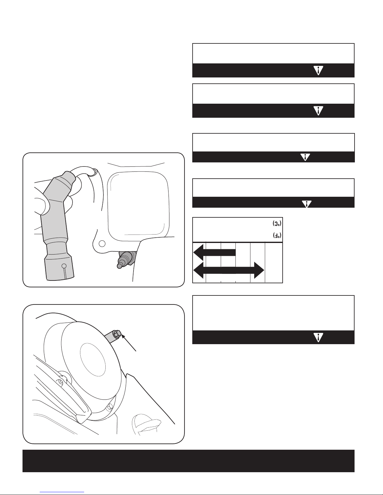
Bouchon de
vidange de
l’huile
Bougie
Gaine de la bougie
19
brosse à bougie si vous voulez l’utiliser à nouveau.
ou si l’isolateur est fendu ou écaillé. Nettoyez la bougie avec une
Examinez soigneusement la bougie. Jetez-la si elle paraît usée 2.
démonter. Voir la Figure 23.
Dégagez la gaine de la bougie et utilisez une clé à bougie pour la 1.
AVERTISSEMENT
bougie doit être correct et la bougie ne doit pas être encrassée.
Pour assurer le bon fonctionnement du moteur, l’écartement de la
toutes les 100 heures de fonctionnement.
heures de fonctionnement. Changez la bougie une fois par saison ou
REMARQUE: Vérifiez la bougie une fois par saison ou toutes les 25
AVERTISSEMENT
très attention de ne pas les toucher jusqu’à ce qu’ils aient refroidi.
Le silencieux seront chauds si le moteur vient d’être arrêté. Faites
faites pas tourner le moteur si la bougie n’est pas installée.
Ne vérifiez pas l’état de la bougie si celle-ci est débranchée. Ne
Vérification de la bougie
tout contact.
Figure 23
Laver les mains avec de l’eau et du savon dès que possible après
ATTENTION
Resserrez le capuchon/jauge à huile sans la visser.7.
abréger la durée de vie du moteur.
L’emploi d’une huile non détergente ou pour moteur à 2 temps peut
ATTENTION
(1,10 litre).
a une capacité de 37 oz.
tion de l’huile. Le carter
tableau de recommandale niveau d’huile. Voir le
recommandée et vérifiez
Faites le plein avec l’huile 6.
fond.
jauge à huile, serrer à
Resserrez le capuchon/5.
5W-30
0º 20º 40º-20º
0W-30
Synthetic
-30º -20º -10º 0º
-40º
Figure 22
aux installations de recyclage agrémentées.
gnez-vous auprès des autorités locales ou 1-800-4MY-HOME quant
réglementée. Ne la jetez pas avec les ordures ménagères. RenseiL’huile usagée est un déchet dangereux dont l’élimination est
AVERTISSEMENT
homologué.
Videz l’huile en inclinant le moteur dans un récipient recyclable 4.
Retirez le bouchon de vidange de l’huile. Voir la Fig. 22.3.
vidange de l’huile.
Placez un récipient recyclable homologué sous le bouchon de 2.
capuchon d’essence bien serré.
jusqu’à ce qu’il tombe en panne d’essence. Vérifiez que le
Videz le carburant du réservoir en laissant tourner le moteur 1.
la suite.
fonctionnement et toutes les cinquante heures ou chaque saison par
REMARQUE: Changer l’huile après les cinq premières heures de
Vidange de l’huile à moteur
SERVICE ET ENTRETIEN
Page 47

18
4. Vissez la jauge à huile à fond avant de mettre le moteur en marche.
soit entre les repères haut (H) et le bas (L). Voir la Fig. 21.
est bas, ajoutez lentement de l’huile jusqu’à ce que le niveau d’huile
3. Enlevez le capuchon de remplissage de l’huile. Si le niveau d’huile
Figure 21
et bas.
repères haut
entre les
Remplissez
sans la visser.
2. Enfoncez la jauge à huile dans le goulot de remplissage de l’huile
à huile.
1. Enlevez le capuchon de remplissage de l’huile et essuyez la jauge
tions SG et SF (qui figurent sur les bidons d’huile correspondants).
établis par les fabricants automobiles américains pour les classificateur à 4 temps ou équivalente, satisfaisant ou surpassant les critères
Utilisez une huile hautement détergente de première qualité pour moexcessivement.
Le carter a une capacité de 37 oz. (1,10 litre). Ne remplissez pas
le niveau est satisfaisant. Voir le tableau de recommandation de l’huile.
Vérifiez le niveau d’huile avant chaque emploi pour vous assurer que
REMARQUE: Vérifier le niveau d’huile avant chaque utilisation.
les pièces se soient immobilisées.
lubrifier, de réparer ou d’inspecter la souffleuse. Attendez que toutes
Débrayez toutes les commandes et arrêtez le moteur avant de
AVERTISSEMENT
de l’huile
remplissage
Capuchon de
Vérification d’huile de moteur
ENTRETIEN DU MOTEUR
qu’il tombe en panne d’esssence.
Avant le remisage Système de carburant1. Laissez le moteur tourner jusqu’à ce 1.
les 100 heures
Tous les ans ou toutes
les 50 heures
Tous les ans ou toutes
les 25 heures
Tous les ans ou toutes
Cinq premières heures Huile à moteur1. Changez1.
et toutes les 5 heures
Après chaque emploi
Lubrifiez avec une huile légère.4.
bile à usages multiples.
Lubrifiez avec une graisse automo-3.
Lubrifiez avec une huile légère.2.
Vérifier1.
Nettoyer3.
Serrer ou remplacez 2.
Vérifier1.
Bougie1. Changez1.
Huile à moteur1. Changez1.
de la tarière
Arbre de transmission et arbre 4.
Roues3.
Bielles de commande et pivot2.
Bougie1.
doigts
Dispositif de protection des 3.
commandes
Alentours du silencieux et 2.
Niveau de l’huile à moteur1.
Intervalle Article Service Logistique de service
en effectuant tout réglage ou toute réparation.
toujours des lunettes de sécurité pendant l’utilisation du tracteur ou
Sears la plus proche de vous.
1-800-4-MY-HOME® pour localiser la station technique agréée par
pour enregistrer les opérations effectuées. Adressez-vous à Sears au
entretiens et intervalles recommandés. Utilisez le carnet d’entretien
Suivez le calendrier d’entretien ci-dessous. Le tableau énumère les
AVERTISSEMENT
terre contre le moteur pour éviter tout démarrage accidentel. Portez
soient immobiles. Débranchez le fil de la bougie et mettez-le à la
commandes et arrêtez le moteur. Attendez que toutes les pièces
Avant d’effectuer toute opération d’entretien, débrayez toutes les
CALENDRIER DES OPÉRATIONS D’ENTRETIEN
SERVICE ET ENTRETIEN
Page 48

17
Figure 20
débrayées.
les roues. Pour arrêter la tarière les deux poignées doivent être
4. Lâchez la commande de la transmission pour arrêter la tarière et
transmission soit débrayée.
maintient la tarière engagée jusqu’à ce que la commande de la
3. Débrayez la commande de la tarière ; le mécanisme de blocage
sans cesser de projeter la neige.
de la tarière pour permettre au conducteur puisse orienter la goulotte
REMARQUE: Cette même poignée permet de bloquer la commande
est embrayée.
Ne changez pas de vitesse quand la commande de la transmission
commande de la transmission pour avancer. Lâcher-la pour arrêter.
2. Alors que la commande de la tarière est embrayée, pressez la
guidon gauche. Lâchez la poignée pour arrêter les tarières.
pressez la poignée d’embrayage gauche de la tarière contre le
1. Pour embrayer les tarières et pour commencer à projeter la neige,
POUR EMBRAYER LES TARIÈRES
pour avancer la souffleuse; lâchez-la pour arrêter.
les goupilles de cisaillement.
Arrêtez le moteur de la souffleuse et retirez la clé avant de remplacer
AVERTISSEMENT
ment ne sera pas couvert par la garantie de la souffleuse.
d’autres pièces en raison de l’utilisation d’autres goupilles de cisaille738-04124A. Tout dégât à la boîte d’engrenages des tarières ou à
des goupilles autres que les goupilles Sears nº 88389/pièce d’origine
Ne remplacez JAMAIS les goupilles de cisaillement des tarières avec
AVERTISSEMENT
remplacement des goupilles de cisaillement.
dans la section «Entretien» de cette notice d’utilisation à propos du
du guidon, comme à la Figure 20. Consultez le chapitre «Tarières»
la notice d’utilisation ou sont placées dans le panneau en plastique
Des goupilles de cisaillement de remplacement sont fournies avec
CISAILLEMENT
REPLACEMENT DE LES GOUPILLES DE
2. Pressez la commande de la transmission contre le guidon droite
habitué.
REMARQUE: Utilisez une vitesse lente jusqu’à ce que vous soyez
la vitesse adaptée aux conditions présentes.
(F) ou à l’une des deux positions de marche arrière (R). Choisissez
changement de vitesse à l’une des six positions de marche avant
1. Avec l’obturateur à la position Fast (lapin), placez le levier de
POUR EMBRAYER LA TRANSMISSION
3. Essuyez toute humidité des commandes sur le moteur.
pas démarrer sans la clé.
pas surveillé. Rangez la clé dans un endroit sûr. Le moteur ne peut
d’un démarrage non autorisé du moteur lorsque l’équipement n’est
2. Retirez la clé de contact Le fait de retirer la clé réduira les risques
Placez l’obturateur à la position « Off ».
1.
aurait pu s’y accumuler.
moteur pendant quelques minutes pour sécher toute l’humidité qui
Quand le déblaiement de la neige est terminé, laissez tourner le
ARRÊT DU MOTEUR
UTILISATION
Page 49

16
une.
tourne. Arrêtez-le après l’emploi et retirez la clé de contact, s’il y en a
enfants, ne laissez JAMAIS le moteur sans surveillance quand il
Pour éviter toute utilisation non surveillée, en particulier par des
AVERTISSEMENT
le volet de départ à la position « Run ».
moitié fermé pendant quelques instants. Puis, déplacez lentement
hésite, faites-le à nouveau démarrer avec le volet de départ à
bouton du volet de départ vers la position « RUN ». Si le moteur
5. Au fur et à mesure que le moteur chauffe, tournez lentement le
MENT à sa position initiale. Répétez si besoin est.
pas brutalement contre le guidon. Laissez la corde revenir LENTEalors démarrer. Ne lâchez pas la poignée pour qu’elle ne revienne
davantage de force pour surmonter la compression. Le moteur doit
sentiez une légère résistance. Tirez ensuite rapidement et avec
4. Tirez doucement sur la poignée du démarreur jusqu’à ce que vous
l’amorçage.
appuyant. Par temps froid, il sera peut-être nécessaire de répéter
une seule fois. Couvrez toujours l’évent du bouton de l’amorceur en
l’évent du bouton de l’amorceur. Si le moteur est chaud, appuyez
3. Appuyez trois fois sur le bouton de l’amorceur en couvrant toujours
de départ à la position « RUN ».
(démarrage à froid). Si le moteur est chaud, tournez le volet
2. Tournez le bouton du volet de départ à la position VOLET FERMÉ
1. Placez l’obturateur à la position « FAST » .
Ne tirez pas sur la corde du démarreur quand le moteur tourne.
AVERTISSEMENT
Démarreur à lanceur
débrancher la prise au moteur.
reur électrique. Débranchez toujours la prise murale avant de
7. Quand le moteur tourne, débranchez le fil électrique du démar-
le volet de départ à la position « Run ».
moitié fermé pendant quelques instants. Puis, déplacez lentement
hésite, faites-le à nouveau démarrer avec le volet de départ à
bouton du volet de départ vers la position « RUN ». Si le moteur
6. Au fur et à mesure que le moteur chauffe, tournez lentement le
démarreur électrique est surchargé.
alors temporairement pour laisser le démarreur refroidir si le
de protection en cas de surcharge thermique ; le système s’arrête
du démarreur. Le démarreur électrique est équipé d’un dispositif
route. Quand le moteur démarre, lâchez immédiatement le bouton
5. Appuyez sur le bouton du démarreur pour mettre le moteur en
l’amorçage.
appuyant. Par temps froid, il sera peut-être nécessaire de répéter
une seule fois. Couvrez toujours l’évent du bouton de l’amorceur en
l’évent du bouton de l’amorceur. Si le moteur est chaud, appuyez
4. Appuyez trois fois sur le bouton de l’amorceur en couvrant toujours
de départ à la position « RUN ».
(démarrage à froid). Si le moteur est chaud, tournez le volet
3. Tournez le bouton du volet de départ à la position VOLET FERMÉ
.
2. Placez l’obturateur à la position « FAST »
volts C.A. à trois trous mise à la terre dans un endroit bien-aéré.
Branchez l’autre extrémité du fil dans une prise de courant de 120
1. Branchez le fil électrique dans le démarreur, sur le moteur.
ÉLECTRIQUE.
à 3 fils mis à la terre (G.F.I.), N’UTILISEZ JAMAIS LE DÉMARREUR
procédez comme suit: Si votre domicile n’est pas équipé d’un système
Si vous avez une prise de courant à trois trous relié à la terre,
électricien.
la terre. Si vous n’êtes pas certain, renseignez-vous auprès d’un
Vérifiez que le câblage de votre maison comporte trois fils reliés à
électrique. N’utilisez pas le démarreur électrique par temps pluvieux.
soigneusement toutes les instructions avant d’utiliser le démarreur
d’une décharge électrique qui pourrait blesser le conducteur. Suivez
volts, C.A. Il doit toujours être relié à la terre pour éviter la possibilité
à trois fils et il est conçu pour fonctionner sur un courant de 120
Ce démarreur (en option) est équipé d’un fil et d’une prise électrique
AVERTISSEMENT
Démarreur électrique (sur certains modèles)
insérée dans le commutateur d’allumage.
REMARQUE: Le moteur ne peut pas démarrer à moins que la clé soit
position. Ne tournez pas la clé.
2. Enfoncez la clé dans la fente. Assurez-vous qu’elle se met bien en
sont débrayées (relâchées).
1. Assurez-vous que les commandes de la tarière et de l’entraînement
ture de fonctionnement normale.
minutes. Il n’atteindra en effet sa puissance maximale qu’à la tempéraREMARQUE : Laissez le moteur s’échauffer pendant quelques
inflammables.
N’utilisez pas de liquide d’allumage sous pression. Les vapeurs sont
N’approchez jamais les mains et les pieds des pièces en mouvement.
AVERTISSEMENT
POUR FAIRE DÉMARRER LE MOTEUR
pour l’expansion du carburant.
le carburant atteigne l’indicateur pour laisser suffisamment de place
réservoir excessivement. Faites le plein du réservoir jusqu’à ce que
Voir l’encadré de la Figure 15. Prenez soin de ne pas remplir le
2. Un indicateur du niveau de carburant se trouve dans le réservoir.
dévissez-le.
1. Nettoyez les alentours du capuchon du réservoir d’essence et
cigare ou toute autre source incandescente.
ou quand le moteur est chaud. Éteignez toute cigarettes ou pipe, tout
jamais le plein d’essence à l’intérieur, pendant que le moteur tourne
extrêmement inflammable et les vapeurs sont explosif. Ne faites
Faites très attention en manipulant de l’essence. L’essence est
AVERTISSEMENT
UTILISATION
Page 50

15
tout reste de neige ou de glace de la goulotte d’éjection.
la commande de la tarière pendant quelques secondes pour dégager
6. Tenez-vous au poste de conduite (derrière la souffleuse) et embrayez
use.
de la tarière. Remettez la clé de contact et faites démarrer la souffle-
ne respirez pas les vapeurs d’essence.
• Évitez tout contact répété ou prolongé de l’essence avec la peau et
en marche.
Vérifiez que les éclaboussures ont séché avant de mettre le moteur
Les éclaboussures et les vapeurs d’essence peuvent s’enflammer.
• Faites attention de ne pas renverser d’essence en faisant le plein.
bouchon est bien en place et serré à fond.
d’essence dans le goulot de remplissage). Vérifiez ensuite que le
• Ne remplissez pas excessivement le réservoir (il ne doit pas y avoir
vous remisez l’essence.
proximité de la tondeuse pendant que vous faites le plein ou là où
Ne fumez pas et n’autorisez aucune flamme nue ou étincelle à
• Faites le plein dans un endroit bien aéré quand le moteur est arrêté.
L’ESSENCE E85.
poussière ou de l’eau pénétrer dans le réservoir. N’UTILISEZ PAS DE
et d’essence ou une essence sale. Évitez de laisser de la saleté, de la
ter-butyléther) peut être utilisée). N’utilisez jamais un mélange d’huile
essence contenant jusqu’à 10% d’éthanol ou 15% de MTBE (méthylpour minimiser les dépôts dans la chambre de combustion). Une
Utilisez une huile automobile (sans plomb ou à faible teneur en plomb
Essence
AVERTISSEMENT
INCLINEZ VERS LE HAUTE
VERS LA GAUCHE
GOULOTTE
INCLINEZ VERS LE BAS
soit entre les repères haut (H) et le bas (L).
est bas, ajoutez lentement de l’huile jusqu’à ce que le niveau d’huile
sans la visser.
à huile.
4. Vissez la jauge à huile à fond avant de mettre le moteur en marche.
l’encrassement des bougies
excessive d’huile causera de la fumée, des démarrages difficiles ou
REMARQUE : Ne remplissez pas excessivement. Une quantité
3. Enlevez le capuchon de remplissage de l’huile. Si le niveau d’huile
2. Enfoncez la jauge à huile dans le goulot de remplissage de l’huile
1. Enlevez le capuchon de remplissage de l’huile et essuyez la jauge
plane et d’arrêter le moteur avant de vérifier le niveau d’huile.
REMARQUE: Assurez-vous de placer la machine sur une surface
paragraphes de la page 18 pour tout renseignement supplémentaire.
a une quantité d’huile suffisante dans le moteur. Consultez les différents
Vérifiez le niveau d’huile avant chaque emploi pour vous assurer qu’il y
Cette machine est expédiée avec le plein d’huile dans le moteur.
Huile
sur la machine et dans ce notice avant le fonctionnement.
Lisez, comprenez, et suivez toutes les instructions et les consignes
VERS LA DROITE
GOULOTTE
POUR TOURNER LA
BOUTON-POUSSOIR
AVERTISSEMENT
POUR FAIRE DÉMARRER LE MOTEUR
5. Replacez l’outil de dégagement sur l’attache à l’arrière de l’habitacle
la glace qui s’est accumulée dans la goulotte.
4. Utilisez l’extrémité en forme de pelle pour déloger et retirer la neige ou
l’arrière de l’habitacle de la tarière.
3. Détachez l’outil de dégagement de la goulotte de sa position sur
Off ». Enlevez la clé de sécurité.
2. Arrêtez le moteur en déplacant l’interrupteur à bascule à la position «
blocage de la traction/tarière.
1. Débrayez la manette de commande de la tarière et la manette de
la goulotte et l’ouverture de la goulotte:
neige et de glace dans la goulotte, procédez comme suit pour nettoyer
attache. Servez-vous de cet outil pour éliminer les accumulations de
Cet outil est maintenu sur l’arrière de l’habitacle de la tarière par une
attache.
Cet outil est maintenu sur l’arrière de l’habitacle de la tarière par une
sées avant de déboucher.
jusqu’à ce que toutes les pièces en mouvement se soient immobiligoulotte obstruée. Arrêtez le moteur et restez derrière des guidons
N’utilisez jamais vos mains pour déboucher un ensemble de la
Outil de dégagement de la goulotte
levier de commande vers l’avant ou tirez-le vers l’arrière.
• Pourmodifierl’angle/ladistancedeprojectiondelaneige,poussezle
vers la gauche.
le bouton du levier de commande et tournez le levier vers la droite ou
• Pourmodifierl’orientationdelaprojectiondelaneige,appuyezsur
POUR TOURNER LA
BOUTON-POUSSOIR
COMMANDE DE LA GOULOTTE
tableau de bord.
La commande d’orientation de la goulotte se trouve sur la gauche du
Commande de la goulotte à 4 fonctions
UTILISATION
Page 51

14
la transmission de votre machine.
de changer de vitesse. Autrement, vous risquez d’user excessivement
REMARQUE : Lâchez toujours la commande de la transmission avant
MARCHE
ARRÊT
COMMANDE DE LA TRANSMISSION
commandes, les tarières et les roues s’arrêtent.
tarières continueront à fonctionner. Quand le conducteur lâche les deux
conducteur peut lâcher la commande des tarières (sur la gauche). Les
embrayée en même temps que la commande de la transmission, le
interrompre la projection de la neige. Si la commande des tarières est
pour que le conducteur puisse changer l’orientation de la goulotte sans
La commande de la transmission permet aussi de bloquer les tarières
contre le guidon pour embrayer les roues. Lâchez-la pour les arrêter.
Elle se trouve sur la droite du guidon. Serrez la manette de commande
TRANSMISSION/DES TARIÈRES
BLOCAGE DE LA COMMANDE DE
COMMANDE D’ORIENTATION DES ROUES
que vous soyez plus habituéaux commandes.
REMARQUE: Utilisez la souffleuse dans des espaces dégagés jusqu’à ce
vers la droite ou serrez celle de gauche pour tourner vers la gauche.
en dessous des poignées. Serrez la commande de droite pour tourner
Les commandes d’orienation des roues de droite et de gauche se trouvent
COMMANDE D’ORIENTATION DES ROUES
Le phare s’allume quand le moteur tourne.
PHARE (le cas échéant)
prise de courant de 120 volts.
Elle exige l’utilisation d’une rallonge à 3 fiches pour l’extérieur et une
BOÎTE DE COMMUTATION ÉLECTRIQUE
courant de 120 volts.
le démarreur électrique du moteur s’il est branché dans une prise de
Le fait d’appuyer sur le bouton de démarrage électrique enclenche
BOUTON DE DÉMARRAGE ÉLECTRIQUE
MARCHE
ARRÊT
Tirez sur la poignée du démarreur pour démarrer le moteur.
POIGNÉE DU DÉMARREUR
COMMANDE DE LA TARIÈRE
Lâchez-la pour arrêter.
contre le guidon pour embrayer la tarière et pour déblayer la neige.
Elle se trouve sur le guidon gauche. Serrez la commande de la tarière
COMMANDE DE LA TARIÈRE
mande est placée à la position « STOP ».
Il permet de régler le régime du moteur et arrête celui-ci si la com-
OBTURATEUR
Enlevez le capuchon pour faire le plein.
CARBURANT
CAPUCHON DU RÉSERVOIR DE
Enlevez le capuchon pour verifier le niveau d’huile et pour faire le plein.
ARRÊT
MARCHE
COMMUTATEUR DE CHAUFFAGE DES POIGNÉES
après avoir utilisé la souffleuse.
à la position « On ». Poussez le commutateur à la position « Off »
souffleuse. Pour que les poignées chauffent, poussez le commutateur
Ce commutateur se trouve sur l’arrière du tableau de commande de la
(le cas échéant)
POIGNÉES
COMMUTATEUR DE CHAUFFAGE DES
CAPUCHON/JAUGE D’HUILE
par le goulot de remplissage.
Il est possible de vérifier le niveau d’huile à moteur et de faire le plein
PLEIN D’HUILE
temps froid.
dans le carburateur du moteur pour aider à faire démarrer le moteur en
L’enfoncement du bouton d’amorcage force le carburant directement
AMORÇEUR
UTILISATION
Page 52

13
UTILISATION
pour être soufflée.
neige pour aider à la neige de tomber dans les tarrières
démarrage du moteur.
du volet de départ ferme la plaque sur le carburateur et facilite le
tournant le bouton dans le sens des aiguilles d’une montre. Le bouton
Le volet de départ est trouvé sur l’arrière du moteur et est activé en
VOLET DE DÉPART
que les barres de coupe pénètrent le haut du banc de
conditions normaux. Manoeuvrez la souffleuse de sorte
importante de neige. Utilisez au besoin dans des
Les barres de coupe servent en cas d’accumulation
BARRES DE COUPE (le cas échéant)
électrique
démarreur
Bouton du
Faisant ainsi la casserez.
REMARQUE: Sortez la clé à mi-distance pour arrêter le moteur.
sans la tourner. Retirez la clé quand la machine n’est pas utilisée.
plus lente des deux. et deux est la plus rapider.
La souffleuse a deux marches arrière (R2), R1 étant la
Marche arrière
La clé de contact est en fait un dispositif de sécurité. Insérez la clé
CLÉ DE CONTACT
«Réglages ».
recouvertes de gravier ou de pierre concassée. Consultez le chapitre
si la neige est tassée et abaissez-les pour travailler sur des surfaces
Positionnez les patins en fonction de la surface de travail. Redressez-les
PATINS
la plus lente et la position 6 la plus rapide.
La souffleuse a six marches avant (F). La position 1 est
Marche avant
choisir la vitesse et la direction de déplacement.
Il se trouve au milieu du tableau de bord et sert à
LEVIER DE VITESSES
expliquées ci-dessous et représentées à la Figure 19.
Maintenant que votre souffleuse est prête à travailler, il est temps de vous familiariser avec ses commandes et diverses caractéristiques,
Figure 19
électrique
Boîte de commutation
Vidange de l’huile
Obturateur
départ
Volet de
Patins
Tarières
contact
Clé de
d’essence
Niveau
/Jauge à huile
Capuchon
démarreur
Poignée du
Commande d’orientation des roues
Commande de la tarière
Amorceur
Silencieux
(Levier de commande)
Commande de la goulotte à 4 fonctions
Levier de vitesses
coupe
Barre de
Goulotte
de la goulotte
dégagement
Outil de
carburant
réservoir de
Bouchon du
Phare
de la transmission
Commande
Page 53

12
tarière.
10. Répétez le test pour vérifier l’ajustement de la commande de la
9. Resserrez ensuite le vis à six pans supérieur.
le bas pour augmenter la tension).
8. Redressez le support vers le haut pour obtenir plus de jeu (ou vers
Figure 18.
six pans supérieur du support de la commande de la tarière. Voir la
7. Pour ajuster à nouveau le câble de commande, desserrez le vis à
avant d’ajuster à nouveau le câble de la tarière.
moteur. Attendez que TOUTES les pièces se soient immobilisées
retournez immédiatement à la position de conduite et arrêtez le
pièce ne bouge. Si la tarière n’est pas complètement immobile,
6. Vérifiez que la tarière est totalement immobilisée et qu’aucune
et « relevée »,. placez-vous devant la machine.
5. Avec la manette de commande de la tarière à la position débrayée
Répétez cette opération plusieurs fois.
4. Attendez environ dix secondes avant de débrayer la tarière.
enclenchez la tarière.
Figure 18
3. Tenez-vous à la position de conduite (derrière la souffleuse) et
souffleuse.
selon les instructions dans la notice d’utilisation qui accompagne la
2. Choisissez un endroit bien aéré et faites démarrer la souffleuse
doit présenter très peu de jeu SANS toutefois être tendu.
1. Débrayez la commande et placez-la en position «relevée». Le câble
Vérifiez le réglage de cette commande de la façon suivante :
souffleuse pour la première fois et au début de chaque saison d’hiver.
Faites ce test de la commande de la tarière avant d’utiliser la
souffleuse fonctionne sans risque et correctement.
instructions. Effectuez tous les ajustements pour vérifier que votre
Avant d’utiliser votre souffleuse, lisez et suivez soigneusement les
AVERTISSEMENT
Test de la commande de la tarière
MONTAGE
Page 54

11
Figure 17 - Acier patin
fond.
3. Serrez les écrous, les rondelles (le cas échéant) et les boulons à
en contact avec le sol pour éviter leur usure inégale.
2. Vérifiez que toute la surface inférieure des patins est de niveau et
patins à la position voulue. Voir la Figure 16 et Figure 17.
rondelles (le cas échéant) et les boulons ordinaires. Placez les
1. Ajustez les patins en desserrant les contre-écrous à embase,
Pour ajuster les patins :
renseignement sur la disponibilité de patins en polymère.
chalcanthite, castine par ex.). Appelez le 1-800-4MY-HOME pour tout
mager les surfaces recouvertes de pierres naturelles (grès,
L’emploi d’une souffleuse équipée de patins en acier peut endom-
AVERTISSEMENT
entre le sol et la lame plate.
patins à la position la plus haute pour assurer un dégagement maximal
Figure 16 - Polymer patin
souffleuse sur une surface recouverte de gravier, réglez les patins à la
REMARQUE : Si pour une raison quelconque, vous devez utiliser la
déblayer est irrégulière.
• Utilisezlespositionsintermédiaireoubaselorsquelasurfaceà
position plus haute sur l’habitacle.
• Pourdéblayercomplètementlaneige,placezlespatinsàla
corporelles et des dégats matériels.
de gravier qui, s’il est projeté par la tarière, peut causer des blessures
Il est déconseillé d’utiliser la souffleuse sur une surface recouverte
AVERTISSEMENT
souffleuse à neige.
l’expédition. Ajustez-les vers le bas, si besoin est, avant d’uiliser la
Les patins de la souffleuses à neige sont ajustés vers le haut pour
Patins
RÉGLAGES
MONTAGE
Page 55

10
Figure 15
la Figure 15.
éviter toute interférence avec la poignée du démarreur à lanceur. Voir
passer la partie détendue du faisceau de câbles dans l’attache pour
inférieur doit être enfoncée dans le trou du guidon inférieur. Faites
La borne sur l’attache qui maintient le faisceau de câbles sur le guidon
(le cas échéant)
Faisceau de câblage du phare
Figure 14
recommandée est indiquée sur le flanc du pneu.
l’ensemble pneu et jante et causer des blessures graves. La pression
excessive à l’installation des talons peut provoquer l’explosion de
pression doit toujours être égale dans tous les pneus. Une pression
Ne dépassez jamais la pression recommandée par le fabricant. La
AVERTISSEMENT
pneus selon le besoin.
le flanc des pneus et réduisez (ou augmentez) la pression dans les
souffleuse. La pression recommandée par le fabricant est indiquée sur
Avant l’utilisation, vérifiez la pression des pneus avant d’utiliser la
Les pneus sont gonflés excessivement pour l’expédition.
Pression des pneus
disponibilité en stock.
1-800-4MY-HOME pour tout renseignement concernant le prix et la
Si votre souffleuse n’est pas équipée de barres de coupe, appelez le
boulonnerie enlevée précédemment.
comme illustré à la Figure 14. Maintenez-les en place avec la
• Positionnezlesbarresdecoupepourqu’ellesfontfaceàl’avant
qui maintiennent les barres de coupe en place.
• Enlevezlesboulonsordinairesendévissantlesécrousàsixpans
sont assemblées à l’envers sur l’habitacle des tarières.
• Surlesmodèlessiéquipés,lesbarresdecoupeetlaboulonnerie
Elles servent en cas d’accumulation importante de neige.
Barres de coupe (le cas échéant)
MONTAGE
Page 56

Outil de
dégagement de la
goulotte
9
Figure 13
effectuez tous les ajustements pour vérifier que votre souffleuse.
tionnement. Lisez et suivez soigneusement les instructions et
à «Test de la commande de la tarière» dans le chapitre « FoncAVERTISSEMENT: Avant d’utiliser votre souffleuse, référez-vous
l’attache-câble et jetez-le avant d’utiliser la souffleuse.
l’arrière de l’habitacle de la tarière avec un attache-câble. Coupez
REMARQUE: Pour l’expédition, le fil électrique est maintenu sur
Figure 11
pour dégager l’obstruction.
en mouvement se soient arrêtées avant d’utiliser l’outil de nettoyage
le moteur et restez derrière le guidon jusqu’à ce que toutes les pièces
Ne débouchez jamais une goulotte obstruée avec vos mains. Arrêtez
AVERTISSEMENT
marche. Voir la Figure 13.
à l’usine. Coupez l’attache-câble avant de mettre la souffleuse en
montage et un attache-câble sur l’arrière de l’habitacle de la tarière
L’outil de dégagement de la goulotte est fixée avec un support de
Outil de dégagement de la goulotte
Figure 12
Figure 10
goupilles de cisaillement.
«Entretien» de cette notice d’utilisation à propos du remplacement des
illustré à la Figure 12. Consultez le chapitre «Tarières dans la section
notice d’utilisation ou dans le panneau en plastique du guidon comme
Remplacement des goupilles de cisaillement sont fournies avec la
cisaillement (en option)
Remisage de la goupille de
enlevée précédemment. Voir la Figure 11.
goulotte avec l’écrou à oreilles, l’axe de chape et la goupille fendue
9. Fixez l’ensemble de rotation de la goulotte au support de la
goulotte» au chapitre «Réglages».
pignon, si besoin est. Référez-vous au «Tige de commande de la
l’enclenchement de la tige de la commande de la goulotte dans le
REMARQUE : Le deuxième trou est employé pour réaliser davantage
précédemment. Voir la Figure 10.
au commande de la goulotte avec la goupille fendue enlevée
8. Fixez l’extrémité ronde de la tige de la commande de la goulotte
MONTAGE
Page 57

Vue de face
Levier de commande
8
Figure 9
pignon. Voir la Figure 9.
la tige de la commande de la goulotte (trou vers le haut) dans le
7. Tout en soutenant l’arrière du pignon, insérez l’extrémité hex. de
goulotte. Voir la Figure 8.
restent placés sur le côté gauche de la tige de la commande de la
6. Vérifiez que tous les câbles sont acheminés dans le guide et qu’ils
Figure 6
commande
Levier de
de 1 heure
à la position
.
Figure 8
commande
Levier de
Haut
le haut pour assurer le pivotement complet de la goulotte.
vers la droite comme illustré à la Figure 6 et la flèche sur le pignon sur
REMARQUE : Le levier de commande devrait être légèrement incliné
du tableau de bord.
REMARQUE : Le pignon est placé sur le devant de l’unité en dessous
soit placé vers le haut (voir la Figure 7.
la Figure 6) pour que la flèche indicateur en argent sur le pignon
5. Pivotez le levier de commande jusqu’à la position de 1 heure (voir
sur le levier de commande.
REMARQUE : La goulotte ne tournera pas sans serrer le déclencheur
Figure 5
Figure 7
vers le haut. Voir la Figure 5.
trous sur l‘ensemble de rotation de la goulotte devraient être placés
goulotte par la main pour faire face à l’avant de la souffleuse. Les
4. Serrez le déclencheur sur le levier de commande et pivotez la
MONTAGE
Page 58

7
Figure 4
Figure 3A.
fendue et l’axe de chape sur le support de la goulotte. Voir la
trouvent sur la commande de la goulotte ainsi que la goupille
1. Retirez la goupille fendue, l’écrou à oreilles et la vis hex. qui se
Goulotte
Figure 2
oreilles à ce temps. Voir la Figure 4.
hex. enlevé précédemment mais ne le fixez pas avec l’ecrou à
goulotte placée sous le panneau de bord. Réinstallez le boulon
3. Placez la goulotte sur sa base avec la tige de la commande de la
Figure 3B
goulotte
Support de la
guidon inférieur.
b. Serrez les boutons qui maintiennent le guidon supérieur sur le
guidon supérieur avec le guidon inférieur.
a. Redressez le guidon supérieur comme à la Figure 1. Alignez le
Figure 1
goulotte. Voir la Figure 3B.
(trou se dirigeant vers le haut) au fond dans la commande de la
2. Insérez l’extrémité ronde de la tige de la commande de la goulotte
Figure 3A
Base
Goulotte
Figure 1.
souffleuse, sont bien alignés avec les rouleaux de guidage. Voir la
2. Assurez-vous que les deux câbles, sur la partie inférieure de la
1. Placez le levier de vitesses dans la 6e position de marche avant.
modèles de souffleuse.
toutes les traits discutées dans ce notice sont applicables à tous les
Commande de la goutlotte
REMARQUE: Cette notice d’utilisation couvre plusieurs modèles, pas
déterminés du poste de conduite, derrière la souffleuse.
REMARQUE: Les côtés droit et gauche de la souffleuse sont
MONTAGE
Page 59

6
CS00071
pour nettoyer la goulotte.
servir de l’outil de dégagement
se soient arrêtées avant de vous
jusqu’à ce que toutes les pièces
et restez derrière les guidons
la goulotte. Arrêtez le moteur
dégager une obstruction dans
servez jamais de vos mains pour
AVERTISSEMENT : Ne vous
souffleuse en marche.
l’usine. Coupez l’attache-câble avant de mettre la
Cet outil a été fixé avec un attache-câble à
cumulations de neige et de glace dans la goulotte.
avec une attache. Cet outil sert à dégager les acmaintenu sur le dessus de l’habitacle de la tarière
Un outil de dégagement de la goulotte est
de la goulotte
dégagement
Outil de
ÉTIQUETTES DE SÉCURITÉ
Page 60

5
fonctionnement. permettez le moteur et le silencieux de se refroidir avant de les toucher.
Les pièces de moteur, particulièrement le silencieux, deviennent extrêmement chaudes lors du
AVERTISSEMENT - SURFACE CHAUDE
N’utilisez pas le démarreur électrique du moteur par temps pluvieux.
AVERTISSEMENT – SECOUSSE ÉLECTRIQUE
d’échappement contiennent du monoxyde de carbone, un gaz inodore et mortel.
Ne faites jamais fonctionner un moteur à l’intérieur ou dans un bâtiment mal ventilé. Les gaz
AVERTISSEMENT – MONOXYDE DE CARBONE
Laissez le moteur refroidir pendant au moins deux minutes avant de refaire le plein.
AVERTISSEMENT – L’ESSENCE EST UN PRODUIT INFLAMMABLE.
Cette machine peut ramasser et projeter des objets, ce qui peut causer des blessures graves.
AVERTISSEMENT – OBJETS PROJETÉS
turbine ou de la goulotte. Les pièces en mouvement peuvent amputer mains et pieds.
N’approchez pas les mains ou les pieds des pièces en mouvement, de l’habitacle des tarières/de la
AVERTISSEMENT – TARIÈRES EN MOUVEMENT
mouvement sont à l’intérieur.
N’approchez pas les mains de l’ouverture d’éjection pendant que la machine fonctionne. Des lames en
AVERTISSEMENT – LAMES EN MOUVEMENT
mouvement sont à l’intérieur.
N’approchez pas les mains de l’ouverture d’éjection pendant que la machine fonctionne. Des lames en
AVERTISSEMENT – LAMES EN MOUVEMENT
avant d’essayer d’assembler et d’utiliser la machine.
Veuillez lire et suivre toutes les instructions sur la machine et vous assurer de bien les comprendre
VEUILLEZ LIRE LA OU LES NOTICES D’UTILISATION.
Symbole Description
la machine et vous assurer de bien les comprendre avant d’essayer d’assembler et d’utiliser la machine.
Cette page illustre et explique les symboles de sécurité qui peuvent se trouver sur cette machine. Veuillez lire et suivre toutes les instructions sur
ÉTIQUETTES DE SÉCURITÉ
Page 61

4
6.2.09
pour le pot d’échappement de cette machine.
La station technique agréée la plus proche peut vous fournir un pare-étincelles
l’utilisateur de la machine.
Si un pare-étincelles est utilisé, il doit être maintenu en bon état de marche par
locaux (le cas échéant).
étincelles, conformément aux lois et règlements provinciaux ou
le système d’échappement du moteur n’est pas muni d’un pareterrain non entretenu, recouvert de broussailles ou d’herbe si
à combustion interne et elle ne doit pas être utilisée sur un
AVERTISSEMENT : Cette machine est équipée d’un moteur
Pare-étincelles
Three Way Catalyst (TWC) le cas échéant.
systèmes de contrôle des émissions de gaz suivants : Engine Modification (EM) et
pour fonctionner avec de l’essence sans plomb ordinaire et peuvent être dotés des
l’agence EPA fédérales pour SORE (petit équipement hors route) sont certifiés
Les moteurs certifiés conformes aux normes régulatrices de la Californie et de
Avis concernant les émissions de gaz
réglage de l’usine du régulateur.
entraîner son fonctionnement à des vitesses dangereuses. Ne modifiez jamais le
modification du réglage du régulateur peut provoquer l’emballement du moteur et
Pour éviter toute blessure grave ou fatale, ne modifiez pas du tout le moteur. Toute
Ne modifiez pas le moteur.
blessures graves ou mortelles.
Le non-respect de ces recommandations peut causer des accidents et des
sécurité sont en bon état de marche et ne sont pas usés de façon excessive.
technique agréée pour vous assurer que tous les dispositifs mécaniques et de
machine neuve ou faites inspecter la machine chaque année par une station
fonctionnement. Au terme de cette durée de vie utile moyenne, achetez une
ce produit a une durée de vie utile moyenne de sept (7) ans, ou 60 heures de
tion Agency” (EPA - Agence américaine de protection de l’environnement),
la sécurité des produits de consommation) et la “U.S. Environmental Protec-
14. D’après la Consumer Products Safety Commission (CPSC - Commission sur
13. Ne faites pas tourner le moteur si la bougie n’est pas installée.
raccords ne sont pas fendillés et ne fuient pas. Remplacez-les au besoin.
12. Vérifiez souvent que la conduite, le réservoir, le capuchon d’essence et les
hors-saison.
11. Consultez toujours la notice d’utilisation quant aux instructions de remisage
fourneau, un sèche-linge ou autre appareil à gaz).
flamme, une étincelle ou une veilleuse (d’un chauffe-eau, un radiateur, un
10. Ne remisez jamais la machine ou les bidons d’essence à l’intérieur s’il y a une
avant de remiser la souffleuse.
neige de la tarière et éviter que l’ensemble de la tarière et de la turbine ne gèle
9. Laissez la machine fonctionner pendant quelques minutes pour éliminer la
risquent de nuire à la nature et à l’environnement.
8. Respectez les règlements concernant l’élimination des déchets et liquides qui
besoin.
7. Prenez soin des étiquettes de sécurité et d’instructions et remplacez-les au
d’utilisation de la machine.
réglages nécessaires. Consultez le chapitre «Réglages» dans la notice
6. Vérifiez fréquemment que les commandes fonctionnent bien et faites les
de mauvaises performances et compromettre la sécurité de l’utilisateur.
conformes aux spécifications de l’équipement d’origine peuvent donner lieu à
par des pièces authentiques seulement. L’utilisation de pièces qui ne sont pas
mesure de sécurité, vérifiez souvent tous les composants et remplacez-les
5. Les plaques de raclage et les patins de la souffleuse s’usent avec l’usage. Par
s’emballer, ce qui peut être dangereux.
4. Ne modifiez pas le réglage du régulateur et ne laissez pas le moteur
vous assurer qu’elle n’est pas endommagée.
machine en bon état de marche. Examinez soigneusement la machine pour
3. Vérifiez régulièrement que les boulons et vis sont bien serrés et maintenez la
réparation ou l’examen de la machine.
la terre pour empêcher tout démarrage accidentel pendant le nettoyage, la
complètement immobilisée. Débranchez le fil de la bougie et mettez-le à
les commandes et arrêtez le moteur. Attendez que la tarière/turbine se soit
2. Avant de nettoyer, de réparer ou d’examiner la machine, débrayez toutes
les réglages dans cette notice d’utilisation.
fonctionnent correctement. Consultez les chapitres concernant l’entretien et
1. Ne modifiez jamais les dispositifs de sécurité. Vérifiez souvent qu’ils
ENTRETIEN ET REMISAGE
3. Servez-vous toujours d’un outil de dégagement, jamais de vos mains.
turbine.
2. Attendez 10 secondes pour vous assurer de l’immobilisation des lames de la
1. ARRÊTEZ LE MOTEUR.
Pour dégager la goulotte d’éjection:
Ne vous servez jamais de vos mains pour dégager une goulotte d’éjection.
la cause la plus courante des blessures associées aux souffleuses.
Un contact de la main avec la turbine en mouvement dans la goulotte d’éjection est
OBSTRUÉE
POUR DÉGAGER UNE GOULOTTE
Sears pour assistance.
abordées par cette notice d’utilisation. Contactez votre Centre de Service
21. Faites toujours preuve de bon sens dans des situations qui n’ont pas été
des ecchymoses ou une entorse.
plus vite qu’il n’est possible de lâcher la corde. Ceci peut causer une fracture,
rapide de la corde du démarreur (recul) attire la main et le bras vers le moteur
vous sentiez une légère résistance, puis tirez plus rapidement. La rétraction
20. Pour mettre le moteur en marche, tirez lentement sur la corde jusqu’à ce que
poids de roues, chaînes, cabine etc.)
19. N’utilisez que des accessoires homologués par le fabricant de la machine. (ex.
soient immobilisées avant de déboucher la goulotte.
tourne. Arrêtez le guidon jusqu’à ce que toutes les pièces en mouvement se
goulotte. Ne débouchez pas la goulotte d’éjection pendant que le moteur
Utilisez toujours l’outil de dégagement pour déboucher l’ouverture de la
18. Ne placez jamais votre main dans la goulotte d’éjection ou près de l’admission.
un ajustement quelconque ou d’examiner la machine.
complètement immobilisée avant de déboucher la goulotte d’éjection, de faire
de conduite (derrière les guidons). Attendez que la tarière/turbine se soit
17. Débrayez toutes les commandes et arrêtez le moteur avant de quitter le poste
remettre en marche.
la machine n’est pas endommagée. Réparez tout dégât éventuel avant de la
le moteur si la machine commence à vibrer de façon anormale. Vérifiez que
16. Arrêtez le moteur, débranchez le fil de la bougie et mettez-le à la terre contre
Soyez prudent en reculant.
15. Ne déplacez jamais rapidement la souffleuse sur des surfaces glissantes.
transporter la machine et lorsqu’elle n’est pas utilisée.
14. Débrayez la commande de l’ensemble de la tarière et de la turbine pour
Marchez, ne courrez pas.
insuffisante. Gardez toujours un bon équilibre et tenez fermement le guidon.
13. N’utilisez pas la machine si la visibilité est mauvaise ou si la lumière est
12. Ne fatiquez pas la machine en essayant de déblayer la neige trop rapidement.
machine.
de compagnie et ne permettez jamais à quiconque de se tenir devant la
11. Ne dirigez jamais la neige vers des enfants, des spectateurs et des animaux
ou des dégâts matériels.
voitures, etc. car les débris peuvent ricocher et causer des blessures graves
10. Prévoyez de travailler en évitant de projeter la neige vers des fenêtres, murs,
9. Faites très attention en changeant de direction et en travaillant sur une pente.
gravier. Faites attention aux dangers non évidents et à la circulation.
8. Soyez extrêmement prudent à proximité des routes, allées ou chemins en
brûlures. Ne les touchez pas.
7. Le silencieux et le moteur deviennent très chauds et peuvent causer des
après avoir pris des médicaments.
6. Ne vous servez pas de la machine après avoir bu des boissons alcoolisées ou
inodore très dangereux.
gaz d’échappement du moteur contiennent du monoxyde de carbone, un gaz
5. Ne faites jamais fonctionner la machine dans un local clos ou mal aéré car les
IMPORTANT CONSIGNES DE SÉCURITÉ
Page 62

3
bon état.
Laissez tous les dispositifs de sécurité en place et assurez-vous qu’ils sont en
4. Ne travaillez jamais sans la goulotte d’éjection ou si elle est endommagée.
lorsqu’elles sont relâchées.
les deux directions et revenir automatiquement à la position de débrayage
3. Toutes les manettes de commande doivent fonctionner facilement dans
l’emploi de la machine et pourrait causer des blessures corporelles.
dispositif de sécurité. Ne contournez jamais son rôle ce qui rendrait dangereux
2. La manette de commande de l’ensemble de la tarière et de la turbine est un
Les pièces en mouvement peuvent amputer mains et pieds.
dans l’habitacle de la tarière ou de la turbine ou dans la goulotte d’éjection.
1. Ne placez jamais vos mains ou vos pieds près d’une pièce en mouvement,
UTILISATION
N’utilisez pas un pistolet de distribution à blocage en position ouverte.
réservoir d’essence ou l’ouverture du contenant pendant le remplissage.
m. Maintenez toujours le contact entre le pistolet de distribution et le bord du
d’essence.
contenant d’essence plutôt qu’avec le pistolet de distribution de la pompe
de l’équipement motorisé sur le camion ou la remorque en utilisant un
remorque et faites le plein au sol. Si ce n’est pas possible, faites le plein
l. Si possible, déchargez l’équipement motorisé du camion ou de la
contenants au sol, loin de tout véhicule, pour faire le plein.
camion ou une remorque à revêtement en plastique. Placez toujours les
k. Ne remplissez jamais les contenants d’essence dans un véhicule, un
remiser.
j. Laissez la machine refroidir pendant au moins 5 minutes avant de la
un fourneau, un sèche-linge ou autre appareil à gaz).
une flamme, une étincelle ou une veilleuse (d’un chauffe-eau, un radiateur,
i. Ne remisez jamais la machine ou les bidons d’essence à l’intérieur s’il y a
en marche.
machine. Déplacez la machine et attendez 5 minutes avant de la remettre
h. En cas de débordement, essuyez toute éclaboussure sur le moteur et la
g. Resserrez bien le capuchon d’essence.
environ pour permettre l’expansion du carburant.
f. Ne faites jamais déborder le réservoir. Laissez un espace d’un demi-pouce
plein.
e. Laissez le moteur refroidir pendant au moins deux minutes avant de faire le
pendant que le moteur tourne.
d. N’enlevez jamais le capuchon d’essence et n’ajoutez pas d’essence
c. Ne faites jamais le plein à l’intérieur.
incandescente.
b. Éteignez toute cigarette ou pipe, tout cigare ou toute autre source
a. Remisez le carburant dans des bidons homologués seulement.
immédiatement de vêtements.
votre peau ou sur vos vêtements s’enflammaient. Rincez votre peau et changez
risquent d’exploser. Vous pouvez être grièvement blessé si des éclaboussures sur
de l’essence. Il s’agit d’un produit extrêmement inflammable et les vapeurs
Pour éliminer tout risque de blessure grave, faites très attention en manipulant
Manipulation de l’essence
de commencer à déblayer.
7. Laissez le moteur et la machine s’habituer à la température extérieure avant
d’indications contraires de la part du fabricant).
6. N’essayez jamais de régler le moteur pendant qu’il tourne (à moins
5. Débrayez toutes les commandes avant de mettre le moteur en marche.
gravier ou en pierre concassée.
4. Réglez la hauteur de l’habitacle pour éviter tout contact avec les surfaces en
toutes les machines équipées d’un moteur à démarreur électrique.
3. Utilisez une rallonge à 3 fils et une prise de courant mises à la terre avec
votre stabilité sur des surfaces glissantes.
prendre dans les pièces en mouvement. Portez des chaussures qui améliorent
de bijoux, d’écharpes longues ou de vêtements amples qui risquent de se
2. Ne travaillez pas sans porter des vêtements d’hiver adéquats. Ne portez pas
et vous blesser aux yeux.
ant un réglage ou une réparation. Un objet peut en effet être projeté, ricocher
1. Portez toujours des lunettes de sécurité en utilisant la machine ou en effectu-
trébucher ou qui risquent d’être projetés par la tarière/turbine.
traîneaux, morceaux de bois, fils de fer et autres objets sur lesquels vous pourriez
Examinez soigneusement la zone à déblayer et enlevez tous les paillassons,
PRÉPARATION
7. Soyez toujours prudent pour ne pas glisser ou tomber, surtout en reculant.
Arrêtez la machine si quelqu’un s’approche.
distance d’au moins 75 pieds de la machine quand elle est en marche.
6. Gardez les spectateurs, les animaux de compagnie et les enfants à une
spectateurs, etc.
Prévoyez de travailler en évitant de projeter la neige vers la route, des
5. Les objets projetés par la machine peuvent causer des blessures graves.
tionnement de la machine de s’en servir.
4. Ne permettez jamais à des adultes ne connaissant pas bien le foncservir sous la surveillance étroite d’un adulte.
consignes de sécurité. Ils doivent apprendre à utiliser la machine et s’en
bien comprendre le fonctionnement de la machine et respecter les
la machine. Des adolescents plus âgés doivent lire la notice d’utilisation,
3. Ne permettez jamais à des enfants de moins de 14 ans de se servir de
débrayer rapidement les commandes.
machine avant de vous en servir. Apprenez à arrêter la machine et à
2. Familiarisez-vous avec les commandes et la bonne utilisation de cette
consultation ultérieure et pour commander des pièces de rechange.
marche. Conservez cette notice d’utilisation à un endroit sûr pour toute
figurent sur la machine et dans la notice d’utilisation avant de la mettre en
1. Assurez-vous de lire et de bien comprendre toutes les instructions qui
FORMATION
DANGERAVERTISSEMENT
et instructions qui figurent dans cette notice et sur la machine.
personnes qui peuvent lire, comprendre et respecter les avertissements
Votre responsabilité: Cette machine ne doit être utilisée que par des
graves et même mortelles.
non-respect de ces consignes peut causer des blessures corporelles
amputer mains et pieds et projeter des débris. Par conséquent, le
l’utilisateur peut entraîner des blessures graves. Cette machine peut
appareil motorisé, une négligence ou une erreur de la part de
sécurité qui figurent dans la notice d’utilisation. Comme avec tout
Cette machine doit être utilisée conformément aux consignes de
seulement votre personne et vos biens, mais aussi
pas respectées, peuvent mettre en danger non
de sécurité importantes qui, si elles ne sont
Ce symbole attire votre attention sur des consignes
CE SYMBOLE!
corporelles, RESPECTEZ L’AVERTISSEMENT QUI ACCOMPAGNE
Le non-respect de ces instructions peut entraîner des blessures
notice d’utilisation avant d’essayer de vous servir de cette machine.
ceux d’autrui. Prière de lire toutes les instructions figurant dans cette
IMPORTANT CONSIGNES DE SÉCURITÉ
Page 63

2
d’achat ci-dessus.
Inscrivez le numéro de modèle, le numéro de série et la date
Date d’achat ....................................................................
Numéro de série ..............................................................
Numéro de modèle ...........................................................
NUMÉRO DE MODÈLE
1-800-4-MY-HOME .........................28
Garantie . . . . . . . . . . . . . . . . . . . . . . . . . . . . . . . . .27
anglaise de cette notice d’utilsation)
Pièces détachées (voir la page 26 de la version
Dépannage . . . . . . . . . . . . . . . . . . . . . . . . . . . . . . . 26
TABLE DES MATIÈRES
Remisage hors saison .......................25
Service et Entretien .........................18
Utilisation . . . . . . . . . . . . . . . . . . . . . . . . . . . . . . . . 13
Montage . . . . . . . . . . . . . . . . . . . . . . . . . . . . . . . . . . 7
Symboles de sécurité ........................5
Important consignes de sécurité . . . . . . . . . . . . . . . 3
Page 64

7/ 30 / 2012
769-08239
Visit our web site: sears.ca
Sears Canada Inc., 290 Yonge Street, Toronto, On M5B 2C3
en marche.
avant de mettre la machine
sécurité et les instructions
attentivement les règles de
• PIÈCES DÉTACHÉES
• ENTRETIEN
• UTILISATION
• MONTAGE
• SÉCURITÉ
ATTENTION : Lisez
C459-52216 (28”)
C459-52215 (26”)
Modèle Nos. C459-52213 (24” )
SOUFFLEUSE À NEIGE 24 PO ET 26 PO
®
Notice d’utilisation
 Loading...