

Page 1

Operator's Manual
CRRFTSMRNo
4.25 AMP
TRIMMER / EDGER
Model No. 989,799310
®
• Safety
• Assembly
• Operation
• Maintenance
• Parts
Espafio|
CAUTION:
Before using this product, read Ibis manual and follow airits
Safety Rules and Operating Instructions.
NEED ASSISTANCE ?
CALL 1-800-339-8657
-Sears,-Roebuck and Co., Hoffman Estates, tL 60179 USA IV_RCH 1998
Visil_uFCraftsman website: www.sears.comJcraftsman PN 211868-R
Page 2
Warranty Statement ............ 2
Safety Precautions ............. 2
Assembly .................... 4
Adjustments .................. 6
Operation ................... 7
Replacement Parts ............. 8
Espa_ol ...................... 9
Parts Ordering ........... back cover
FULL ONE YEAR WARRANTY ON CRAFTSMAN TRIMMER / EDGER.
If this Craftsman Trimmer/Edger fails to perform properly due to a defect in material or
workmanship within (1) year from the date of purchase, Sears will repair or replace it,
free of charge.
This warranty does not cover the nylon line.
WARRANTY SERVICE IS AVAILABLE BY RETURNING THE CRAFTSMAN TRIMMER /
EDGER TO PLACE OF PURCHASE OR TO THE NEAREST SEARS SERVICE CENTER.
This warranty gives you specific legal rights, and you may also have other rights which
vary from state to state.
Sears, Roebuck and Co. Dept. D/817WA Hoffman Estates, IL 60179
PLEASE READ
SAVE THESE INSTRUCTIONS
When using an electrical appli-
ance, basic precautions should
always be followed to assure maxi-
mum safety and optimum performance.
Read this manual before assembling and
operating this appliance. Failure to comply
with instructions may result in electrical
shock, burns, fire, or personal injury.
WARNING
TO REDUCE THE RISK OF
ELECTRIC SHOCK, BURNS, FIRE
OR PERSONAL INJURY:
1. FOLLOW ALL SAFETY INSTRUC-
TIONS listedin this manual before and
duringoperation of this trimmer.
2. TO _IE-DUCE THE RISK OF ELEC-
TRIC SHOCK this equiPmenthas a
polarized plug (one blade is wider than
the other). This plug will fit in a polar-
ized outletonly one way. If the plug
does not fitfully in the outlet, reverse
the plug. If itstilldoes not fit, contacta
qualifiedelectricianto install the proper
outlet. Do not change the plug in any
way.
3. INSPECT UNIT FOR DAMAGE to the
housing,cord or plug. Keep all fasten-
.ers_. Do not use if the switch does
not rum the unit off properly. Never use
.
.
unitifcord or plug has been damaged,
or if the motor or unit itselfis not work-
ing as it shouldor has been dropped,
damaged, left outdoorsor dropped in
water. Never operate with any air
opening blocked. Keep air openings
free of debris that may reduce air flow.
Replace damaged pads that are
chipped,cracked or damaged in any
way because they can fly apart and
cause serious injury.
[D]THIS APPLIANCE IS DOUBLE
INSULATED to help protect
against electric shock. Double insula-
tion_onstruction consistsof 2 separate
"layers"of electric insulation.
Appliancesbuiltwith this insulation
system are not intended to be ground-
ed. As a result, the extension cord
used with your unitcan be plugged
intoany conventional 120 volt electri-
cal outlet. Normal safety precautions
must be observed when operating an
electricalappliance. The double insula-
tionsystem is only for added protec-
tionagainst injury resultingfrom a pos-
sible intemai electrical insulationfail-
Ure.
GROUND FAULT CIRCUIT INTER-
RUPTER (GFCI) receptacle may be
used on an outlet or circuit for an
added measure of safety.
Page 3
6. EXTENSION CORD - Use only with
an extensioncord intended for outdoor
use. Match wire gauge to the cord
length. See table below. A 2-wira cord
withouta groundconnection may be
used since this appliance is double
insulated•If in doubt of proper wire
size, use the next heavier gauge.
Please notethat the srhaller the gauge
number,the heavierthe cord.
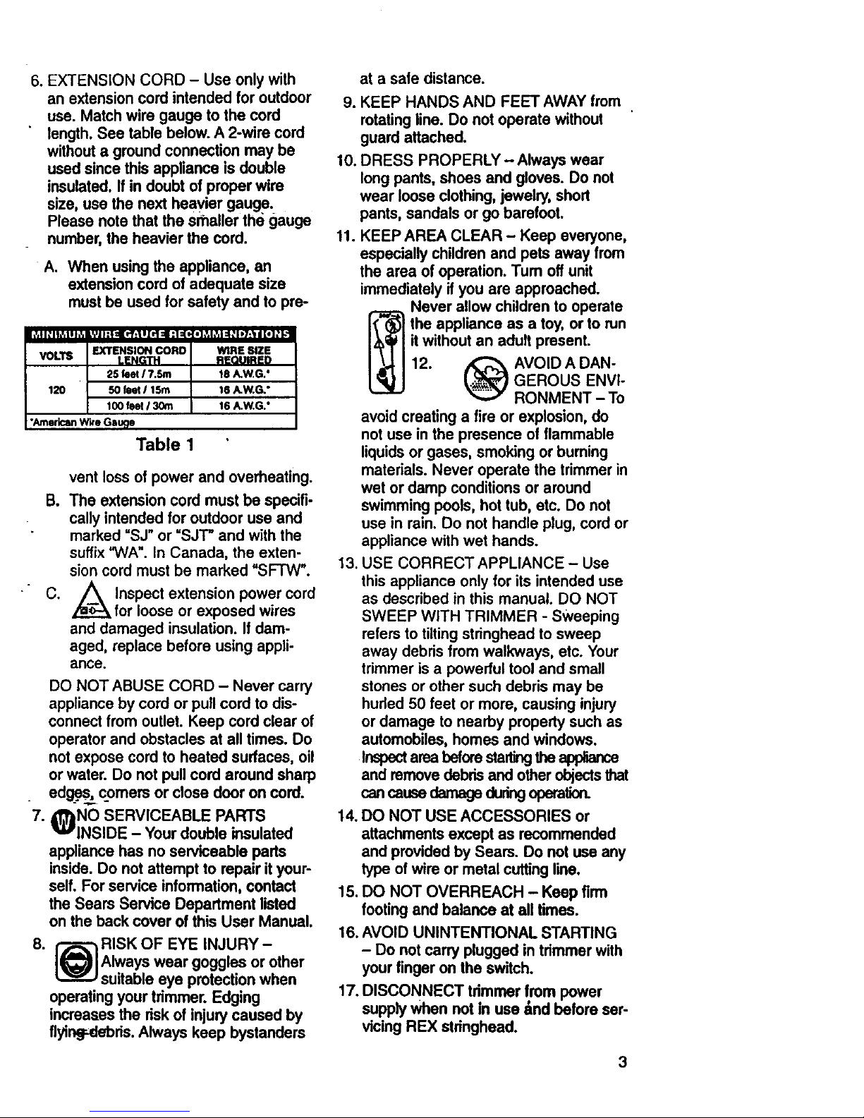
A. When using the appliance, an
extension cord of adequate size
must be used for safety and to pre-
v • i it . • , | • e , IWI_R t=lP'SlZE e •
L 25 foot17.5m .1 18 A.WG,"
120 1 50 feet 115m / t6 A W,G,"t00 feet 13_n 16A.W.G."
"AmericanW.e Gau_e
Table 1
vent loss of power and overheating.
B. The extension cord must be specifi-
cally intended for outdoor use and
marked "SJ" or "SJT" and withthe
suffix"WA". In Canada, the exten-
sion cord must be marked "SFTW".
C. /_ Inspect extension power cord
for loose or exposed wires
and damaged insulation. If dam-
aged, replace before using appli-
ance.
DO NOT ABUSE CORD - Never carry
appliance by cord or pull cord to dis-
connectfrom outlet. Keep cord clear of
operator and obstacles at all times. Do
not expose cord to heated surfaces, oil
or water. Do not pull cord around sharp
edge.._comers or close door on cord.
7. _NO SERVICEABLE PARTS
INSIDE - Your double insulated
appliance has no serviceable pads
inside. Do not attempt to repair it your-
self. For service information,contact
the Sears Service Depadment listed
on the back cover of this User Manual•
8. _ RISK OF EYE INJURY -
Always wear goggles or other
suitable eye protection when
operating your trimmer.Edging
increases the dsk of injurycaused by
flyinff..debds.Always keep bystanders
at a safe distance.
9. KEEP HANDS AND FEET AWAY from
rotatingline. Do not operate without
guard attached.
10. DRESS PROPERLY - Always wear
longpants, shoes and gloves. Do not
wear loose clothing,jewelry, short
pants, sandals or go barefoot.
11. KEEP AREA CLEAR - Keep everyone,
especially children and pets away from
the area of operation. Turn offunit
immediately if you are approached.
_ Never allow children to operate
the appliance as a toy, or to run
itwithout an adult present.
12. _ AVOID A DAN-
_.._ GEROUS ENVI-
RONMENT - To
avoid creating a fire or explosion, de
not use in the presence of flammable
liquids or gases, smoking or burning
materials. Never operate the trimmer in
wet or damp conditionsor around
swimming pools, hot tub, etc. Do not
use in rain. Do not handle plug, cord or
appliance with wet hands.
13. USE CORRECT APPLIANCE - Use
this appliance only for its intended use
as described in this manual. DO NOT
SWEEP WITH TRIMMER - Sweeping
refersto tiltingstringheadto sweep
away debris from walkways, etc. Your
trimmer is a powerful tooland small
stones or other such debris may be
hurled 50 feet or more, causing injury
or damage to nearby property such as
automobiles, homes and windows.
Inspectarea beforestarlingtheal:_
and removedebrisand other objectsthat
cancausedamageduringoperation.
14.DO NOT USE ACCESSORIES or
attachments except as recommended
and providedby Sears. Do not useany
type ofwire or metal cutting line.
15. DO NOT OVERREACH - Keep firm
footing and balance at all times.
16. AVOID UNINTENTIONAL STARTING
- Do not carry plugged in tdmmer with
yourfinger on the sw'dch.
17. DISCONNECT tdmmor from power
supplywhen not in use _nd before ser-
vicing REX stdnghead.
3
Page 4

18. STORE idle trimmer indoors.
Appliance should be stored in a dry,
high or IScked up place - out of the
reach of _hildren.
EXPLANATION OF NOTE,
WARNING, and WARRANTY
SYMBOL
1. A NOTE is used to convey additional
information, or highlight a particular
explanation, or to expand a step
inst=:_ction.
2. A WARNING identifies a procedure
which, if not undertaken or if improp-
erly done, can result in a serious per-
sonal injury or damage to the unit
and/or both.
3._)(WARRANTY SYMBOL) serves
noticethat unless instructions or
procedures are followed, any damage
willvoid the warranty and repairs will
be at owner's expense. Service other
than user maintenance should be per-
formed by a Sears Service Center.
Damage or conditions caused by
improper maintenance practices
which render this product inoperable
will void the manufacturer's warranty.
4. FOR WARRANTY OR SERVICE con-
tact the nearest Sears Service Center.
INTERNATIONAL
SYMBOLS
1. Read the
User Manual.
2. Use of these
personal safety
items is highly
recommended
to reduce the
risk of
injury
SAVE THESE INSTRUCTIONS
CARTON CONTENTS
Check the carton againt the following:
MODEL NO. 799310
• Trimmer
• Debris shield
• Wire guard withwheel
• 5 REX stringheads
if you need assistance, or find parts miss-
ing, call 1-800-339-8657.
ASSEMBLY NOTE: The only assembly
required for your trimmer is to install the
debris shield and adjust the assist handle.
DEBRIS SHIELD INSTALLATION
1. Positionthe motor housingwith string-
head carrier (A) facinq up (Figure 1).
A
Fig. 1
2. S_ide debris shield over motor housing
as shown (Figure 1).
3. Align edging guide with mating
grooves and push firmly in the direc-
tion {hown until an audible snap is
heard (Figure 2).
NOTE: Be certain that edging guide is ori-
ented as shown be ow Once edging
guide, motor housing and debris shield
are mated the connection Is perma-
nent and cannot be removed without a
special tool
I
BE CAREFUL,
THIS WIRE
GUARD CAN BE
INSTALLED
UPSIDE DOWN
Pig.z
4
Page 5

REX DISPOSABLE CU'I-rING HEAD
INSTALLATION AND REMOVAL
NOTE: REX lines are uneven for
ir_provedcutting
INSTALLATION
1. Unplugunit.
2. Positionthe motor housing with the
stringheadcarrier (A) facing up "
(Figure 3).
3. Align disposable stdnghead locking
tabs (B) with correspondingslots (C)
in canrieras shown (Figure 3).
Fig. 3
4. With firm pressure push disposable
stringheadonto carder until an audible
clickis heard (Figure 4).
Fig. 4
REMOVAL
1. Unplug unit.
2. Press red buttonon top of motor hous-
ing to eject used REX disposable
stringhead (Figure 5).
Fig. 5
ADJUSTABLE ASSIST HANDLE
1. Grip underside of assist handle with
thumb and forefinger on either side of
the base of the assist handle as shown
(Figure 6).
NOTE: The assist handle is ratcheted for
variable operating positions. Adjust to a
comfortable position.
3. Release red buttons.
ADJUST SHAFT LENGTH
1. Grip shaft firmly.
2. Push red shaft release button forward
and move handle forward or backward
to desired length (Figure 7).
Fig. 6
2. While depressing red buttons, use
other hand to move assist handle into
•desired-location.
Fig. 7
5
Page 6

NOTE:Shaftmaybe adjustedintrimming 2.Pushredbuttonforward, and rotate
or edging mode. shaft until itstops (Figure 8).
EDGING CONVERSION
1. Grip shaft fi}mly.
KNOW YOUR TRIMMER / EDGER
Fig. 8
SHAFT LOCKING--
BUTTON
HANDLE
ASSIST
HANDLE
RETAINER
REX
EJECT BUTTON (RED)
HOUSING
ROLLER---_
EDGE GUIDE \
SHAFT
"SSED
PLUG
TRIGGER
LASSIST
HANDLE
BUTTON
OPENINGS
;HIELD
REX STRINGHEAD
CARRIER
6
_.-- REX STRINGHEAD
(RAPIDEXCHANGEDISPOSABLESTRINGHEAD)
Page 7

CONNECT THE CORD
1. Ensure the cord is NOT plugged into
a receptacle before starling this pro-
cedure.
2. Make a loop with 8"- 10" (20 - 25cm)
of the end of the extension cord.
3. Place the loop into thegroove atthe
end of the roar handleand lock into
place as shown in Figure 9.
Fig. 9
occurs at proper cuttingpoint. Aiways
cut away from yourself. Do not pull
trimmer in toward yourself.
4. Connect the extension co'rdto the
recessed plug on the trimmer.
5. Plug the extension cord into a recep-
tacle ONLY when you are ready to
operate thetrimmer.
TRIGGER
Squeeze the red on/off triggerto operate
•unit.
TRIMMER OPERATION
1. TRIMMING I MOWING (Figure 10).
Swing trimmer with a smooth even
motionfrom side to side. Do not tilt
the stringhead duringthe procedure.
Keep stringhead at same level for
even depth of cut.
Fig. 11
3. FENCE/FOUNDATION TRIMMING.
Approach trimming around chain link
fences, picket fences, rock walls and
foundationsslowly to cut close without
whipping Stringagainst the barrier. If
the string comes in contactwith rock,
brick walls, or foundations, it will break
or fray. If stringsnags fencing, it will
snap off.
4. TRIMMING AROUND TREES• Trim
around tree trunks with a slow
approach so string does not contact
bark. Walk around the tree trimming
from left to right. Approach grass or
weeds with the tip of the string and tilt
stringheadslightlyforward.
5. SCALPING (Figure 12). Scalping
refers to removal of all vegetation
down to the ground. To do this, tiltthe
sffinghead to your right at about a 30
degree angle from the ground. By
adjustingthe handle you will have bet-
ter controlduring this operation.
Always keep a distance of 100 feet
(30 meters) from other people and
animals when scalping. Do not
attempt this procedure if there isany
chance flyingdebris could injure oper-
ator, other people or cause damage to
property.
Fig. 10
2. CLOSER TRIMMING (Figure 11).
Positiontrimmer straight ahead with a
slighttilt so bottom of stringhead is
ab_L0-ground level and string contact
Fig. 12,
7
Page 8

6.OPERATINGASAN EDGER(Figure
13).Withthe unit configured as an
edger, hold it so the motor is to your
left side so that debris is thrown to the
rear. Always use eyeprotection. This
unit is equipped with an edging wheel
and guide. Use the wheel to support
the weight of the unit as you edge
along flat surfaces such as driveways
and sidewalks.
Fig. 13
7. DO NOT SWEEP WITH TRIMMER
(Figure 14)
Fig. 14
8. DO NOT BUMP TRIMMER (Figure
15).A "bump" willnot advance line.
For fresh line follow See REX
Disposable Cutting Head Installation
and Removal in the Assembly section.
Fig. 15
STRINGHEAD
1. Use Craftsman replacement REX
Stringhead Stock No. 71-85631.
2. Always clean dirt and debris from the
spool and hub prior to using unit,
when the unit is idle, and after per-
forming any type of maintenance.
USER MAINTENANCE
RESPONSIBILITIES
1. _LThis appliance ha_sno user
_gF
serviceable pads. Do not attempt
any repairs. Doing so could create a
hazard and void the manufacturer's
warranty.
2. Unplug the power cord before clean-
ing or performing maintenance or
removing or installing REX string
head.
3. Never douse appliance with liquidor
squid with a garden hose. Clean with
a damp sponge.
4. Keep airopenings on the motor hous-
ing free from any debris to avoid over-
heating.
REX Head - 5 per package
Assist Handle
Debris Shield
Wire Guide with Wheel
Wjr_e without Wheel
30278_-00
324239-61
324448-61
302778-00
324298-00
8
 Loading...