

Page 1

OWNER’S
MANUAL
MODEL NO.
987.889000
CRAFTSMAM
A Caution;
Read and Follow
All Safety Rules
and Instructions
Before Operating
This Equipment.
8 HORSEPOWER 33-INCH MOWER
Assembly
Operation
Customer Responsibilities
Service and Adjustments
Repair Parts
Sears, Roebuck and Co., Hoffman Estates, Illinois 60179 U.S.A.
FORM 1905122 (3/98)
Page 2

SAFETY RULES
A
CAUTION: ALWAYS DISCONNECT SPARK PLUG WIRE AND PLACE WIRE WHERE IT
AA CANNOT CONTACT SPARK PLUG TO PREVENT ACCIDENTAL STARTING WHEN SET- Ak
TING UP, TRANSPORTING, ADJUSTING OR MAKING REPAIRS. **
IMPORTANT
Safe Operation Practices for Walk-Behind Mowers
This cutting machine is capable of amputating hands and feet and throwing objects. Fail
ure to observe the following safety instructions could result in serious injury or death.
8. Do not operate the mower without proper guards,
WARNING:
The engine exhaust from this product
contains chemicais known to the State of
California to cause cancer, birth defects, or
other reproductive harm.
I. GENERAL OPERATION
1. Read, understand, and follow alt instructions on the
machine and in the manuals. Be thoroughly familiar
with the controls and the proper use of the mower
before starting.
2.
Do not put hands or feet near or under rotating parts.
Keep clear of the mower blade and discharge open
ing at all times.
plates, grass catcher or other safety protective de
vices in place.
9. Refer to provided instructions for proper operation
and installation of accessories. Only use acces
sories approved by Sears, Roebuck and Co.
10. Stop the blade when crossing gravel drives, walks,
or roads.
11. Stop the engine and disconnect the spark plug wire
from the spark plug whenever you leave the unit, be
fore cleaning the mower or unclogging the chute.
A
FI
3.
Only allow responsible individuals, who are familiar
with the instructions, to operate the mower.
4.
Clear the area of objects such as rocks, toys, wire,
bones, sticks, etc., which could be picked up and
thrown by the blade.
5.
Be sure the area is clear of other people before
mowing. Stop mower if anyone enters the area.
Keep bystanders at least 25 feet away from the area
of operation.
6.
Do not operate the mower when barefoot or wearing
open sandals. Always wear substantial foot wear.
7.
Do not pull mower backwards unless absolutely nec
essary. Look down and behind before and while
moving backwards.
12. Shut the engine off, wait until the blade comes to a
complete stop, and disconnect the spark plug wire
before installing or removing the mulcher cover or
the optional grass catcher. Make certain that the
grass catcher is securely attached before operating
the mower. Empty the grass catcher after each use-
decomposing debris could generate enough heat to
catch fire.
13. Mow in daylight or good artificial light.
14. Do not operate the mower while under the influence
of alcohol or daigs.
15. Never operate mower in wet grass. Always be sure of
your footing; keep a firm hold on the handle and walk;
never run.
16. Disengage the Wheel Drive Lever on self-propelled
models before starting the engine.
17. If the unit should start to vibrate abnormally, stop the
engine and disconnect the spark plug wire. Then
check immediately for the cause. Vibration is gener
ally a warning of trouble.
A
LOOK FOR THIS SYMBOL TO POINT OUT IMPORTANT SAFETY PRECAUTIONS. IT MEANS-ATTENTION!!! BECOME ALERT!!! YOUR SAFETY IS INVOLVED.
Page 3

SAFETY RULES
18. Always wear safety goggles or safety glasses with
side shields when operating mower.
19. Watch for traffic when operating near, or when cross
ing roadways.
20. Never attempt to carry children or other passengers
on the mower. They could fall off and be seriously in
jured, or they could interfere with the safe operation
of the mower.
21. Check the operation of the Operator Presence Con
trol before each use. See the Customer Responsibili
ties Section of this manual for instructions. If the
mower blades rotate longer than three seconds after
the Operator Presence Control is released, the sys
tem is not working properly. Immediately contact
your local Sears Service Center/Department for in
structions. Do not use the mower until the mecha
nism is repaired.
22. The mower is equipped with a safety discharge
chute, comes with a special mulcher cover and offers
an optional grass catcher. The safety discharge
chute must be working properly at all times. Never
attempt to disconnect or othenwise cause this dis
charge chute to cease working. If used, mulcher
cover or grass catcher attachment must be installed
properly and function correctly. Do not use your
equipment othenwise.
23. Never run the engine in an enclosed area. Engine ex
haust contains carbon monoxide, a deadly gas that is
odorless, colorless, and tasteless. Always run the en
gine outdoors and make sure there is adequate
ventilation.
II. SLOPE OPERATION
Slopes are a major factor related to slip and fall acci
dents which can result in severe injury. All slopes
require extra caution. If you feel uneasy on a slope,
do not mow it.
DO:
Mow across the face of slopes; never up and down.
Exercise extreme caution when changing direction on
slopes. Avoid slopes greater than 150.
Remove objects such as rocks, tree limbs, etc.
Watch for holes, ruts, or bumps. Tall grass can hide
obstacles. .
DO NOT:
Do not mow near drop-offs, ditches, or embankments.
The operator could loose footing or balance.
Do not mow excessively steep slopes.
Do not mow on wet grass. Reduced footing could
cause slipping.
III. CHILDREN
Tragic accidents can occur if the operator is not alert
to the presence of children. Children are often at
tracted to the mower and to the mowing activity.
Never assume that children will remain where you
iast saw them.
1. Keep children out of the mowing area and under the
watchful care of a responsible adult.
2. Be alert and turn mower off if children enter the area.
3. Before and while moving backwards, look behind
and down for small children.
4. Never allow children to operate the mower.
5. Use extra care when approaching blind corners,
shrubs, trees, or other objects that may obscure
vision.
IV. SERVICE
1. Use extra care in handling gasoline and other fuels.
They are flammable and their vapors are explosive.
a) Use only an approved container.
b) Never remove gas cap or add fuel when the en
gine is running. Allow engine to cool before refu
eling. Do not smoke.
c) Never refuel the machine indoors.
d) Never store the machine or fuel container inside
where there is an open flame, such as a water
heater, etc.
e) Move mower away from any gasoline fumes be
fore starting the engine.
2. Never run an engine inside a closed area.
3. Never make adjustments or repairs with the engine
running. Disconnect the spark plug wire and keep
the wire away from the plug to prevent accidental
starting.
4. Keep all nuts and bolts, especially the blade attach
ment bolts, tight and keep equipment in good condi
tion.
5. Never tamper with safety devices. Check their opera
tion regularly. .
Page 4

SAFETY RULES
6. Keep mower free of grass, leaves or other debris
build-up. Clean up oil or fuel spillage. Allow mower to
cool before storing.
7. After striking an object, stop the engine and discon
nect the spark plug wire. Inspect the mower and re
pair, if necessary, before restarting.
8. Never attempt to make mower cutting height adjust
ments whiie the engine is running.
9. Grass catcher components are subject to wear, dam
age and deterioration, which could expose moving
parts or allow objects to be thrown. Frequently check
components and replace with Sears recommended
parts, when necessary.
10. Mower blades are sharp and can cut. Wrap the blade
or wear gloves, and use extra caution when servicing
them.
PI
11. Do not change the engine governor setting or over
speed the engine.
12. Do not touch engine parts which may be hot from
operation. Allow parts to cool completely before in
specting, cleaning or repairing the mower.
13. To access the underside of the mower, tip the mower
rearward. Do not tip the mower forward or on either
of its sides, uniess specifically advised to do so in
this manuai.
14. Maintain or replace safety and instructional decals.
Refer to the Repair Parts Section for replacement
decal information.
Page 5

CONGRATULATIONS on your purchase of a Craftsman
33-lndi Mower. It has been designed, engineered and
manufactured to give you the best possibie dependability
and performance.
Should you experience any problems you cannot easily
remedy, please contact your nearest Seam Service
Center/Department. We have competent, well-trained
technicians and the proper tools to service or repair this
machine.
Please read and retain this manual. The instructions will
help you assemble and maintain your machine properiy.
Always observe the “SAFETY RULES.”
MODEL NUMBER: 987.889000
SERIAL
NUMBER:
_____________________________________
DATE OF
PURCHASE:___________________________________
THE MODEL AND SERIAL NUMBERS WILL BE
FOUND ON A DECAL LOCATED RIGHT SIDE OF
THE MOWER DECK.
YOU SHOULD RECORD BOTH THE SERIAL NUM
BER AND DATE OF PURCHASE AND KEEP IN A
SAFE PLACE FOR FUTURE REFERENCE.
PRODUCT SPECIFICATIONS
HORSEPOWER:
DISPLACEMENT:
8 HP
19.43 CU. IN.
FUEL CAPACITY: 3 Quarts
SPARK PLUG (GAP .030-in.):
Champion RJ-17LM
or equivalent
IGNITION
■ Electronic
NET ENGINE WEIGHT 57 LBS.'
' in Canada, replace spark plug with a resistor plug.
WARNING: This machine is equipped with an internal
combustion engine and should not be used on or near
any unimproved forest-covered, brush-covered or
grass-covered land unless the engine’s exhaust system
is equipped with a spark arrester meeting applicable lo
cal or state taws (if any). If a spark arrester is used, it
should be maintained in effective working order by the
operator.
In the state of California the above is required by law
(Section 4442 of the California Public Resources Code).
Other states may have similar laws. Federal laws apply
on federal lands. This engine is not equipped with a
spark arrestor for the muffler. A spark arrester for the
muffler is available through your nearest Sears autho
rized service center. See the REPAIR PARTS section of
this manual.
MAINTENANCE AGREEMENT
A Sears maintenance agreement is avaiiable on this
product. Contact your nearest Sears store for details.
CUSTOMER RESPONSIBILITIES
□ Read and observe the safety rules.
□ Follow a regular schedule in maintaining, caring for
and using this product.
□ Follow the instmctlons under "CUSTOMER
RESPONSIBILITIES” and “STORAGE" sections of
this manual.
LIMITED TWO-YEAR WARRANTY ON CRAFTSMAN® POWER MOWER
For two years from date of purchase, when this Craftsman® Lawn Mower is maintained, lubricated, and tuned up according to the
operating and maintenance instructions in the owner’s manual, Sears will repair free of charge any defect in material or workmanship.
If this Craftsman® Lawn Mower is used for commercial or rental purposes, this warranty applies for only 90 days from the date of
purchase.
THIS WARRANTY DOES NOT COVER:
• Expendable items which become worn during normal use, such as rotary mower blades, blade adapters, belts, air cleaners and
sparlLDlug.
• Repairs necessary because of operator abuse or negligence, including bent crankshafts and the failure to maintain the equipment
according to the instructions contained in the owner’s manual.
WARRANTY SERVICE IS AVAILABLE BY RETURNING THE CRAFTSMAN® MOWER TO THE NEAREST SEARS SERVICE CENTER/ DE
PARTMENT IN THE UNITED STATES. THIS WARRANTY APPLIES ONLY WHILE THIS PRODUCT IS IN USE IN THE UNITED STATES.
This warranty gives you specific legal rights, and you may also have other rights which vary from state to state.
One year warranty on the following: #38700, #38607. #38712. #38720, #38721, #38725 -
Page 6

TABLE OF CONTENTS
ACCESSORIES AND ATTACHMENTS.
INDEX
Accessories and Attachments
Adjustments:
B
Blade:
,.7
.15
.25
. .8
32
32
..........
2
C OQ
.0|
....
5
c
............
7
............
8
...
13
.5,23
Features/Controls ......................
Fuel Storage
Fuel Type..................................
Gear Select Lever ........
Handlebar;
14
Assembly...............................
.....
SERVICE AND ADJUSTMENTS....
^TnRAOF ...............................
TROUBLESHOOTING
DECALS
...................................
REPAIR PARTS - MOWER......................................
REPAIR PARTS - ENGINE
PARTS ORDERING/SERVICE
F
__ _
13
.......................
G
H
.17, 34
___
17
... .14
.........
.....................
.................
Recoil Stert Rope
Repair Parts
Responsibilities, Customer .. .5, 23
Safety Decals
Safety Rules
Service and Adjustments
Spark Plug........................................26
Specifications
Starting/Stopping Engine....................19
9
Storage
............. .
..............
..............
.....................................36
.
.....................................37
.....................................46
...
.............
Back Cover
R
.............................
.....................................
S
..................................
......................................
....................
.....................................
...........................................
26
34
35
16
37
36
2
26
5
34
Controls:
Customer Responsibilities:
Decals
Engine:
Oil
.26
. 14
. 15
. 16
. 14
. 13
. 15
.25
.32
i-25
.23
.26
.36
. .25
. .24
. .24
. .13
. .16
. .26
. .34
L
Lubrication:
Engine
.....
...........................
Mower
.................................
M
Maintenance:
Agreement ...........................
Schedule
Mowing Tips
Mulching Cover
Off-Season Storage..................
Oil ..........................................
Operation
Operator Presence Control
Options
Parts List
Product Specifications ....
...........................
............................
.......................
0
................................
..................................
P
...............................
.17, 23
........
..........
........
.........21
. .15, 18
.........34
..17, 23
........
.........13
...........
,. .21-27
.
...........
23
23
T
Troubleshooting
Unpacking..........................................8
5
................................
U
W
Warranty
Wheel Drive Control ...........................15
13
7
4
...........................................
OPERATOR’S POSITION
All references in this Manual
to LEFT and RIGHT sides of
thè mower are given from the
operator’s position behind the
handlebars (unless specified
: otherwise).
35
5
Page 7

ACCESSORIES AND ATTACHMENTS
These accessories and attachments were available when the mower was purchased. They are also available at most
Sears retail outlets, catalog and service centers. Most Sears stores can order repair parts for you when you provide
the model number of your unit.
ENGINE
Spark Plug
MOWER
Grass Catcher
Gas Can
Belt
Fuel Stabilizer
Blade
Motor Oil
Page 8
©
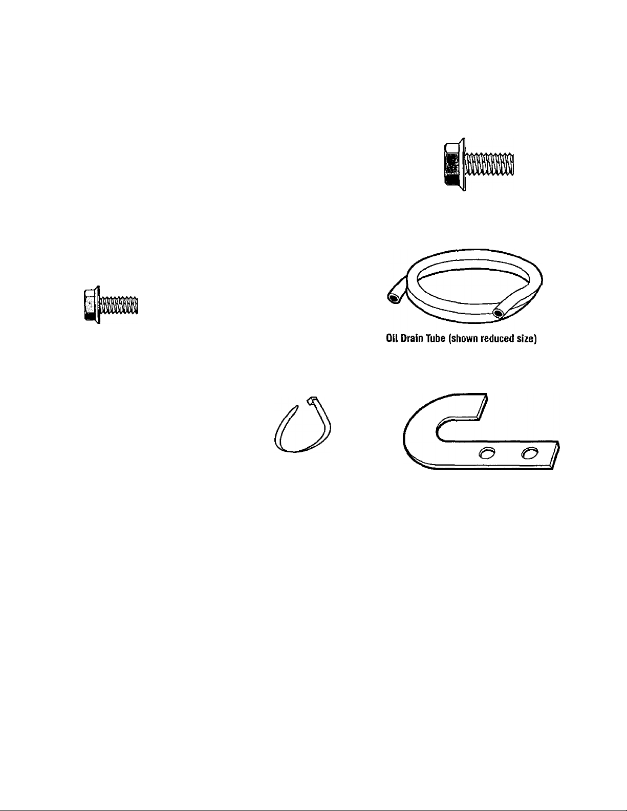
CONTENTS OF HARDWARE PACK
Parts Bag Contents
Flat Washer,
5/16”
Qty;4
Hex Flange Lock Screw,
1/4”-20 X1/2"
Qty:2
PI
Shift Link - Gear Select Lever
{shown reduced size)
Qty:1
Cotter Pin,
3/32" X 5/8”
Qty:6
Hex Flange Lock Nut,
1/4-20”
Qty:2
Plastic Cable Tie
(shown reduced size)
Qty:1
Hex Flange Lock Screw,
5/16”-18 X 3/4”
Qty:2
Qty: 1
Shift Rod Mounting Plate
(shown reduced size)
Qtytl
Page 9

ASSEMBLY
Read these instructions in their en
tirety before you attempt to assem
ble or operate your new equipment.
Your new equipment has been as
sembled at the factory with the ex-
Toots Needed For Assembly:
(1)7/16’ Wrench
(1) 3/8“ Wrench
(2) 1/2“ Wrenches
(1) Needle-nose Pliers
(1) Wire Cutter Pliers
(1) Tire-Gauge
(1) Scissors or Pen Knife
UNPACKING
INSTRUCTIONS
• Inspect your machine immediate
ly. Be sure neither the carton nor
contents have been damaged. If
you find or have reason to sus
pect damage, contact your near
est Sears Service Center/Department for assistance.
• Cut plastic banding with scissors.
Open box flaps and remove any
packing material from around the
machine. Remove any staples
securing bottom of carton to wood
pallet. Lift off carton. Cut metal
straps securing unit to base.
Leave unit on base of pallet dur
ing assembly steps (to safely re
move unit from base, wait until
you have completed assembly
steps 1-2). Before disposing of
the carton or any of the packing
materials, be sure to check them
thoroughly for any small parts.
• Cut plastic tie straps holding three
long control rods to handlebars.
Also remove any packaging
around the handlebars.
• Perform the assembly on a clean,
level surface. If you need to
move the machine, be careful not
to severely bend any of the con
trol cables on the equipment.
ception of those parts left unassem
bled for shipping purposes. To en
sure safe and proper operation of .
your machine, all parts and hard
ware you install or adjust must be
ASSEMBLY STEPS
Before starting any assembly
steps, disconnect the engine
spark plug wire from the spark
plug.
STEP1: Attach Handlebars
• If applicable, cut and remove any
plastic ties holding wheel drive rod
(F, Figure 2-5) to left handlebar and
blade drive rod (C, Figure 2-5) to
right handlebar. Put rods aside.
• Handlebars (A, Rgure 2-2) are
shipped partially assembled with two
screws (Y, Rgure 2-2) loosely instEjIed. It may be necessary to
loosen screws (Y) further to allow the
handlebars to clear the engine air
cleaner.
• Rotate handlebars over engine
and position as shown in Figure 2-2.
Be careful that the handlebars clear
the unit while unfolding. Also, put
end of control rod (E, Figures 2-3
and 2-5) into cut-out (W, Figures
2-2 and 2-3) in back of frame while
rotating handlebars into position.
• Install two 5/16“-18 X 3/4" hex
flange screws (B, Figure 2-2).
• Tighten all four screws (B and Y).
• Secure the engine throttle cable
to the left handlebar with a cable tie
from the hardware bag. Clip off any
excess tie length.
tightened according to the assem
bly instructions. Use the correct
tools as necessary to ensure proper
tightness. .
Figure 2-2: Attach handlebars.
Page 10
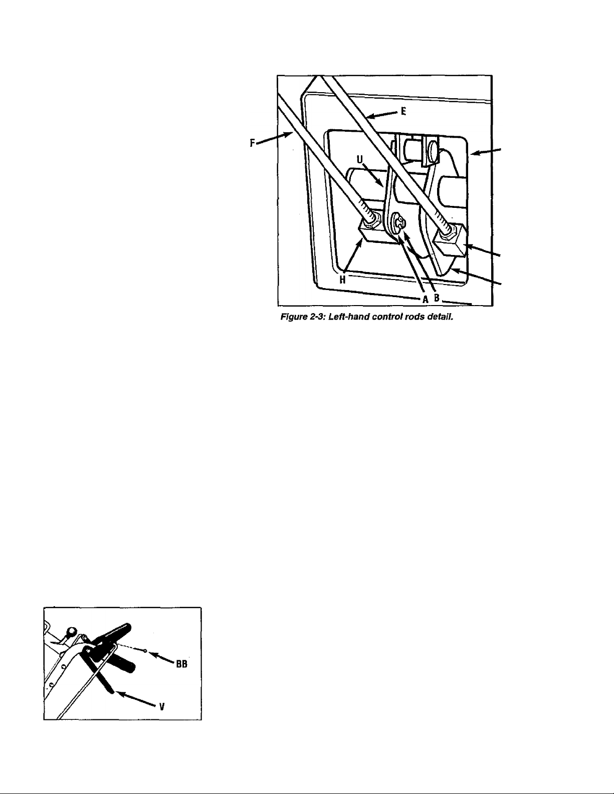
STEP 2: Attach Control Rods
WARNING
The control rods are adjusted
at the factory and should not
require additional adjustment
during assembly. After as
sembling unit, control rod ad
justment should be checked
(and re-adjusted, if neces
sary) according to information
in “Customer Responsibili
ties” Section. Severe person
al injury or property
damage could result from
not following this
instruction.
A. Attach Wheel Drive Control
Rod
• Locate the wheel drive control
rod (F, Figures 2-3 & 2-5) that you
removed from the left handlebar in
Step 1. This rod has a swivel block
(H, Figure 2-3) on one end.
• At left side of engine frame,
insert swivel block (H, Figures 2-3
& 2-5) on wheel drive control rod
into wheel drive control arm (U,
Figure 2-3).
• Add one 5/16” washer (A. Figure
2-3). Secure with cotter pin (B,
Figure 2-3). Bend ends of cotter
pin to secure.
• At upper end of control rod,
secure angled end to Wheel Drive
Control lever (V, Figure 2-4), using
a cotter pin (BB). Bend ends of
cotter pin to secure.
Figure 2~4: Attach wheel drive con
trol rod to lever.
ASSEMBLY
B. Attach Operator Presence
Control Rod:
• Locate control rod (E, Figures.
2-3 & 2-5) attached at upper end
to Operator Presence Control (W,
Figure 2-5).
• At bottom of control rod, insert
swivel block (G, Figures 2-3 &
2-5) into control arm {T, Figure
2-3).
• Add one 5/16” washer and se
cure with cotter pin. Bend ends of
cotter pin to secure.
C. Attach Blade Drive Control
Rod:
• Locate the blade drive control
rod (C, Figure 2-5) that you re
moved in Step 1. Insert one end of
control rod into blade drive bracket
(D, Figure 2-5). Add one 5/16”
washer and secure with cotter pin
(CC). Bend ends of cotter pin to
secure.
• Insert upper end of rod into bot
tom end of Blade Drive Control
lever (J). Add one 5/16” washer
and secure with cotter pin (AA).
Bend ends of cotter pin to secure.
• W
D. Attach and Adjust Gear Select
Lever:
• To remove unit from shipping
crate, hold down Operator Pres
ence Control lever (W, Figure 2-5)
which releases the wheel brake.
• Using the edge of a piece of flat
wood (such as a ruler), remove
the vinyl grip (B, Figure 2-6) from
the gear select lever (I). Place the
wood edge against the edge of the
grip and slowly pull off the grip.
• Insert nylon bushing (Z, Figure
2-6) up into console (L).
• Slide spring and washers (J)
down onto gear select lever.
• Insert gear select lever (I) up
through nylon bushing (Z) in han
dlebar console (L, Figure 2-6).
Guide pin (K) on gear select lever
into groove in shift quadrant (EE).
• Hold lower part of gear select
(ever (I) against bracket (M, Figure
2-7). Position retaining plate (N)
from parts bag in place as shown
in Figure 2-7 (plate below brack
et). Secure plate with two 1/4”-20
X 1/2” long screws (O) and 1/4”-20
locknuts.
• Slide grip (B, Figure 2-6) back
onto upper end of gear select
lever (I).
10
Page 11

ASSEMBLY
• Rotate gear select lever (I, Rgures 2-6 & 2-7) clockwise until pin
(K) on gear select rod stops in the
neutral position detent on the shift
pattern quadrant (Figure 2-6).
• Thread shift link (P, Figure 2-7)
partially into ball-joint (Y).
• Move shift arm (X, Figure 2-7)
from side to side as necessary into
each transmission gear detent un
til transmission is in neutrai.
NOTE: Moving shift arm (X) all
the way to the left, and then one
notch back to the right, should put
transmission into neutral. When ~
transmission is in neutral, unit will
move freely when pushed while
holding the Operator Presence
Control iever (W, Figure 2-5)
down. If transmission is NOT in
neutral, there will be a slight drag
on the wheels when pushing unit.
EE
• When shift arm (X) is in neutral
position, rotate shift link (P) toward
end of gear select lever rod (I).
Adjust length of shift link (P) as
necessary to fit into hole in bottom
of gear select lever (I).
NOTE: Pin (K) on Gear Select
Lever (I) must be held in the neu
tral position detent on the shift
quadrant (see Figure 2-6) while
shift link (P, Figure 2-7) is
adjusted. .
I
Pin (K) must be in this detent
when transmission neutrai is
adjusted.
Figure 2-6: Detail - Gear Select Lever in Neutral (N) position.
11
Page 12
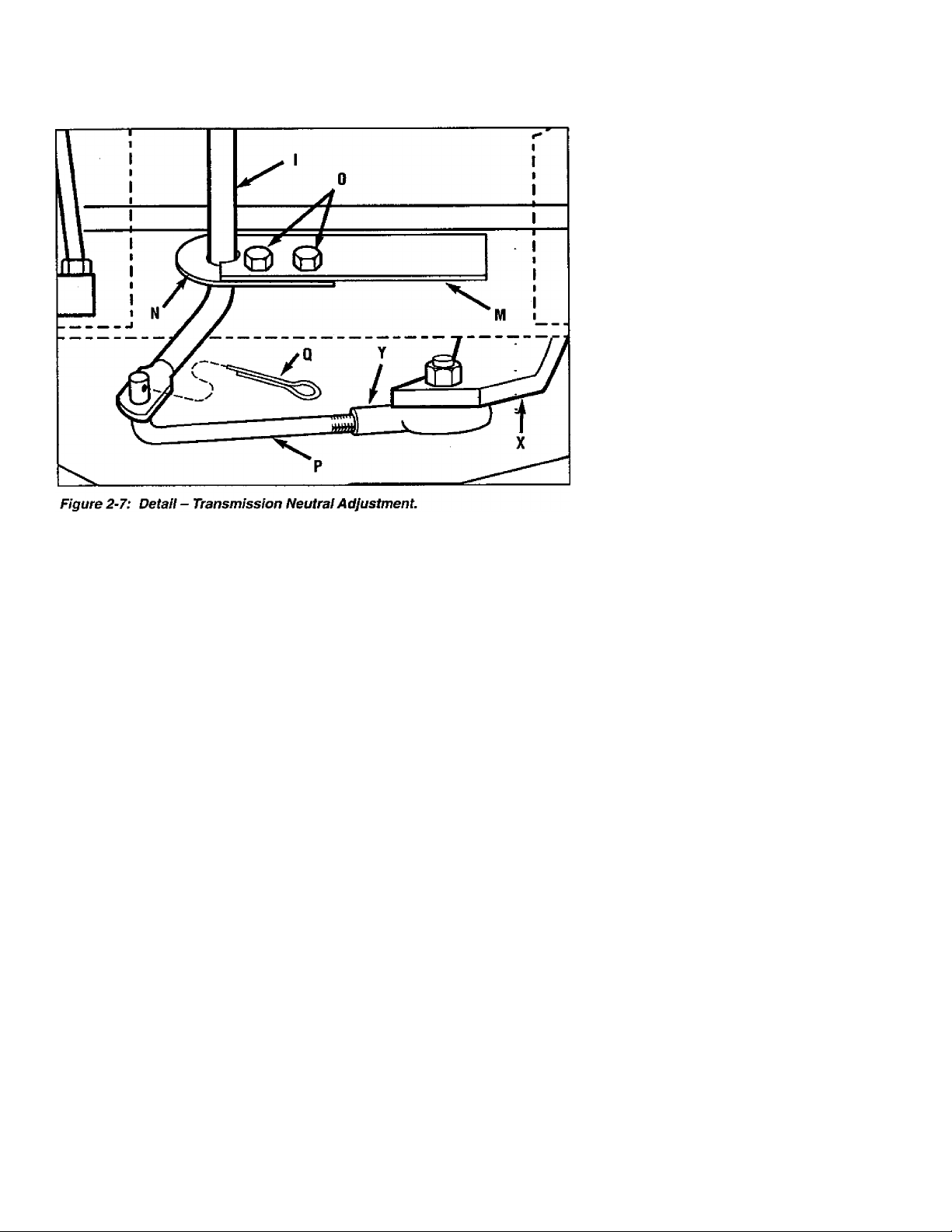
• Insert hooked end of shift link (P,
Figure 2-7) into hole in bottom end
of gear select lever (I) and secure
with cotter pin (Q). Bend ends of
cotter pin. NOTE: It may be nec
essary to lift gear select lever (I) to
install shift link (P).
* Hold down Operator Presence
Control lever (W, Figure 2-5) and
push unit forward and backward.
The wheels should move freely. If
not, adjust length of shift link {P,
Figure 2-7) as necessary.
E. Test Wheel Brake:
Put the Gear Select Lever in in
neutral (N), release all of the con
trol levers, and try to push the unit
forward and backward. The
wheels should not turn. If they do
turn, an adjustment is necessary.
DO NOT OPERATE THE UNIT
UNTIL THE WHEEL BRAKE
MECHANISM HAS BEEN
ADJUSTED AND IS WORKING
PROPERLY. See "Wheel Brake
Adjustment’ in “Customer Respon
sibilities.”
ASSEMBLY
WARNING
Do not use the mower if the
wheels continue to turn after
releasing the Operator Pres
ence Control and the Wheel
Drive Control. Severe per
sonal injury or property dam
age could result if this in
struction is not followed.
WARNING
The control rods are adjusted
at the factory and should not
require additional adjustment
during assembly. After
assembling unit, control rod
adjustment should be
checked {and re-adjusted, if
necessary) according to
information in “Customer Re
sponsibilities” Section. Se
vere personal injury or prop
erty damage could result from
not following this
instruction.
STEP 3: Check Tire Pressure
• Use a tire gauge to check №e air
pressure in the rear tires. The air
pressure should be between 15-20
PSI (20 PSI maximum).
• Keep both tires equally inflated
to help prevent machine from
pulling to one side.
STEP 4: After Assembling and
Before Using Unit
• Read this entire Owner’s Manual
for proper safety, operation and
maintenance information.
• Make sure spark plug wire is
connected to spark plug before
starting unit.
IMPORTANT: MOTOR OIL MUST
BE ADDED TO THE ENGINE
CRANKCASE BEFORE START
ING THE ENGINE. OIL FILLING
INSTRUCTIONS ARE COVERED
IN THE “OPERATION” SECTION.
CAUTION
Unit is shipped without oil in
engine crankcase. DO NOT
start engine until oil has been
added. Severe engine dam
age will result if this instruc
tion is not followed. See “Op
eration” Section ot this man
ual for oil filling procedure.
12
Page 13

OPERATION
KNOW YOUR EQUIPMENT
READ THIS OWNER’S MANUAL AND ALL SAFETY RULES BEFORE OPERATING YOUR EQUIPMENT. Know the
location and function of all features and controls on the equipment. Save this manual for future reference.
MEETS ANSI B71.1 -1996
SAFETY STANDARD
This machine meets voluntary
safety standard B71.1 - 1996,
which is sponsored by the Outdoor
Power Equipment Institute, Inc.,
and is published by the American
National Standards Institute, Inc,
Operating Symbols
Various symbols are used on the
mower to indicate control settings
(your model may not have all of the
symbols). These symbols are
shown below with a description of
their meaning.
V
FAST SLOW
s 6
ENGINE
STOP
ENGAGE DISENGAGE
ENGINE
START
9
N
CHOKE
S
ENGINE
RUN
IP
IMPORTANT: The mower is
equipped with a blade-brake-clutch
control system which is designed
to stop the mower blades within
three (3) seconds after release of
the Operator Presence Control.
This system will stop the blades
but not the engine. Therefore, you
can disengage the blade drive at
anytime without having to stop and
restart the engine. This feature is
particularly useful when you need
to cross gravel drives or rough ter
rain and you do not want the spin
ning blades to strike stones or hid
den obstacles.
LOCATION AND USE OF
CONTROLS
Operator Presence Control
This lever (A, Figure 3-1) regu
lates the operation of the rear
wheel brake and the separate
Blade Drive Control.
To engage the Operator Pres
ence Control, press and hold the
lever against the handlebar grip.
Engaging the lever releases the
brake on the rear wheels (allows
wheels to turn). The engaged po
sition also permits the separate
Blade Drive Control to lock In its
engaged position (allows the mow
er blades to turn).
Releasing the lever (disengaged
position) applies the rear wheel
brake and quickly stops the
wheels. Releasing the lever will
also disengage the Blade Drive
WARNING
The blade-brake-clutch con
trol system should stop the
mower blades within three (3)
seconds after release of the
Operator Presence Control. If
the blades do not stop within
three'(3) seconds, put the En
gine Throttle Control in the
STOP position. Disconnect
the spark plug wire and do not
operate the mower until the
blade-brake-clutch control
system has been repaired!
Control, which will apply a brake
that stops the blades within three
(3)seconds.
Always disengage the Operator
Presence Control before starting
the engine. Always engage this
control before engaging the sepa
rate blade drive or wheel drive
controls. ■
A-OPERATOR
PRESENCE CONTROL
Disengaged
Engaged
Figure 3~1
13
Page 14

OPERATION
Blade Drive Control
Use this lever (B, Figure 3-2) to
engage drive to the mower blades.
To engage the blades, first en
gage the Operator Presence Con
trol (A, Figure 3-2). Then, push the
spring-loaded Blade Drive Control
lever (B) forward until it stays in the
engaged position.
To stop the blades, release the
Operator Presence Control (A).
Doing so will disengage the Blade
Drive Control (B) and automatically
apply the brake that stops the
blades.
. When starting the engine, the
Blade Drive Control should be dis
engaged (released). This helps to
ensure that the blades will not start
turning when the engine starts.
NOTE: Pushing the Blade Drive
Control fonward will engage the
blades even though the Operator
Presence Control is not engaged.
However, this procedure is NOT
RECOMMENDED as you must
maintain constant pressure on the
lever (releasing lever disengages
blades). Always engage the Oper
ator Presence Control before en
gaging the Blade Drive Control.
Gear Select Lever
This lever (C, Figure 3-3) is used
to select any of three forward
ground speeds (1 - Slow, 2 - Medi
um and 3 - Fast), N (Neutral) and
R (Reverse). The gear shift pattern
is shown in Figure 3-4.
To avoid damaging the trans
mission, do not shift gears when
the mower is moving. Select for
ward ground speeds according to
mowing conditions and terrain (use
slower speeds in high grass or on
rough terrain).
For fonward travel, move the
lever into one of the three num
bered settings. To select reverse,
shift to neutral and then puli up on
the lever. Turn the lever to the R
(reverse) position and release the
lever.
Put the lever in N (neutral) to
manually push the mower and
when the mower is not in use.
LIFT FOR
REVERSE
Figure 3-4; Shift pattern on console.
14
Page 15

OPERATION
Wheel Drive Control
Use this lever {D, Figure 3-5) to
engage and disengage drive to the
wheels.
To engage the wheels, first select
a fonward or reverse gear with the
Gear Select Lever and press the
Operator Presence Control (A, Fig
ure 3-5) against the handlebar
grip. Then, squeeze the Wheel
Drive Control lever (D) up against
the handlebar grip. The ground
speed can be varied in any gear by
increasing (to go faster) or de
creasing (to go slower) pressure
on the lever. To avoid sudden ac
celeration, slowly squeeze the
lever when first engaging the
wheels.
Release the Wheel Drive Control
to disengage the wheels. The
Cutting Height Control Lever
This lever (E, Figure 3-6) is used
to adjust the mower cutting height.
The cutting height can be adjusted
from 1 to 4 inches.
Turn the lever clockwise to raise
the cutting height or counterclock
wise to lower the cutting height. A
decal and pointer (not illustrated)
wheels will gradually slow to a
stop. NOTE; To stop the wheels
quickly, release the Operator Pres
ence Control along with the Wheel
Drive Control.
When starting the engine, the
Wheel Drive Control should be dis
engaged (released). This helps to
ensure that the wheels will not start
turning when the engine starts.
CAUTION
Do not engage the Wheel
Drive Control without first en
gaging the Operator Presence
Control. Doing so could re
sult in wear or damage to the
wheel brake mechanism.
on the right side of the mower deck
show the cutting height settings
ranging from A (highest) to G (low
est). Note that the actual cutting
heights will vary according to soil
conditions.
A ~ OPERATOR
PRESENCE CONTROL
Disengage
Engage
Engage
)isengage
/”
D-WHEEL
DRIVE CONTROL
Figure 3-5
Mulcher Cover
To use the mulching feature, in
sert the mulcher cover (Figure 3-7)
securely in the right side of the
deck beneath the discharge chute.
Insert the front tab of the cover
into the mower front support brack
et (AA, Figure 3-7). Then push the
cover into place by sliding the
cover rearward, making sure that
the slot (BB) in the cover is com
pletely engaged in the rear edge of
the deck opening.
Remove the mulcher cover if you
want to do side-discharge mowing.
The mulcher cover is
pre-installed at the factory.
NOTE: The mulcher cover is
designed to keep the discharge
chute raised up while you mow.
When the cover is removed, the
discharge chute lowers.
DANGER
Before installing or re
moving mulching cover,
stop engine, wait for parts
to stop moving, and dis
connect spark plug wire.
15
Figure 3-7
Page 16

OPERATION
Engine Thrnttle Control
This lever (F, Figure 3-8) is used
to adjust engine speeds and to
stop the engine. Always run en
gine at fast speed setting for best
mower performance. The throttle
settings are shown to the right.
Kl
CHOKE - Use when
starting a cold engine.
FAST - Use during mower
operation.
SLOW - Use when idling
engine.
STOP - Stops engine.
s
BEFORE OPERATING
Pre-Operation
Checklist
Perform the following checks before each use of your
machine;
□ Review; “Safety” and “Operation” sections of manual.
□ Check for loose or missing hardware. Tighten or replace
before starting engine.
□ Check the engine oil level. Refer to “Customer Respon
sibilities” section for instructions.
□ Check the fuel level in the fuel tank (refer to next page
for instructions).
□ Check all levers for freedom of movement. Do not start
engine if any lever does not function correctly.
■B>
Figure 3-8
Engine Recoil Starter
The engine recoil starter (H, Fig
ure 3'9) is used to "pull-start" the
engine. Do not pull the recoil
starter until you have read the Oper
ation Section.
□ Adjust the blade cutting height (refer to this Section for
instructions).
□ Inspect the area to be mowed and remove any debris.
□ Check that all guards and shields are in place and prop
erly secured.
□ Check the installation of the mulcher cover in the right
side deck opening. Remove the mulcher cover if you
want to side discharge the grass.
□ Check air pressure in rear tires at first use and every 25
operating hours. Maintain 15-20 PSI (maximum 20 PSI)
in each tire. Keep tires inflated equally or mower may
pull to one side.
□ Attach the spark plug wire to the spark plug.
Figure 3-9
16
Page 17

BEFORE STARTING ENGINE
OPERATION
Add Motor Oil
• Only use high quality detergent
oil rated with API service classifica
tion SR SG or SH. Select the oil's
SAE viscosity grade according to
your expected operating tempera
ture. Above 320R use SAE 30;
below 320R use 5W30.
NOTE; Although multi-viscosity oils
(5W30, .10W30 etc.) improve start
ing in cold weather, these oils will
result in increased oil consumption
when used above 320R Check
engine oil more frequently to avoid
possible engine damage from run
ning low on oil.
• Be sure that engine is level. Re
move dipstick (A, Figure 3-10).
• Fill with recommended oil to be
tween “Full” and “Add” marks on
dipstick (approximately 32 oz.).
Pour slowly and do not overfill.
While pouring, stop frequently, re
insert dipstick until it is seated
completely, remove and check oil
level. (Wipe dipstick each time be
fore re-inserting.) Replace dipstick
securely.
• Check oil before each use. Add if
needed.
• Change oil after the first 2 operat
ing hours and every 25 operating
hours thereafter (more often in ex
tremely dusty or dirty conditions).
Fill Fuel Tank
• stop engine and allow it to cool
for three minutes before removing
fuel fill cap (B, Figure 3-10). Do
not check fuel level or add fuel
while indoors.
• Clean area around fuel fill cap
and remove fill cap. Fill gas tank
with clean, fresh unleaded gaso
line. Do not mix oil with gasoline.
• Using a funnel or spout, fill tank
to 1/2 inches below bottom of fuel
tank filler neck to prevent spills and
to allow for fuel expansion.
WARNING: Experience indicates
that alcohol blended fuels (gasohol
or using ethanol or methanol) can
attract m'oisture which leads to
separation and formation of acids
during storage. Acidic gas can
damage the fuel system of an en
gine while in storage. To avoid
problems, the fuel system should
be emptied before storage for 30
days or longer. Drain the gas tank,
start the engine and let it run until
the fuel lines and carburetor are
empty. Use fresh fuel next season.
See STORAGE instructions for ad
ditional information. Never use en
gine or carburetor cleaner products
in the fuel tank or permanent dam
age may occur.
DANGER
Gasoline is highly flammable and its vapors are explosive. Read and fol
low these precautions to help avoid severe personal injury or property
damage.
• Do not remove gas cap or add gasoline if engfne is running or still hot
from operation. Allow engine to cool at least three minutes before
refueling.
• Keep open flame, matches, sparks, or smoking materials away from fuel
tank and fuel container.
• Do not fill fuel tank indoors. After filling, wipe up any spills and move
machine away from gasoline fumes before starting engine. Securely re
place the caps on the fuel tank and fuel container.
• Do not fill fuel tank completely. Fill tank to 1/2” below bottom of filler
neck to provide space for fuel expansion.
• Store gasoline in an approved fuel container and in a well-ventilated area.
Store it safely out of the reach of children.
• Do not store gasoline where vapors may reach an open spark or flame, or
where ignition sources (such as hot water heaters, space heaters, furnaces,
clothes dryers, stoves, electric motors, etc.) are present.
Figure 3-10
• Install fill cap securely and wipe
up any spilled gasoline.
17
Page 18

OPERATION
Ad|ust Mowet Cutting Height
The cutting height can be adjust
ed from 1 to 4 inches by rotating
the Cutting Height Control lever (A,
Figure 3-11).
Choose cutting heights accord
ing to grass conditions and terrain.
In heavy or tail grass, it is usually
better to make the first cut at a
higher setting and then make a
second cut at the desired setting.
When mowing in rough terrain, a
higher setting is recommended as
it will minimize the chances of the
blade striking the ground or hidden
obstructions.
1. Release all mower controls
before adjusting cutting height
2. Turn Cutting Height Control
lever clockwise to raise cutting
height or counterclockwise to lower
cutting height. A decal and pointer
(not illustrated) on the right side of
the mower deck show cutting
height settings ranging from A
(highest) to G (lowest). Note that
actual cutting heights will vary
according to the grass and soil
conditions.
CAUTION
To avoid personal injury, do
not adjust cutting height
while wheels or blades are
turning. Release all handle
bar controls and wait for all
motion to stop before adjust
ing cutting height.
Test Blade*Brake*Glutch
Control System
The mower is equipped with a
blade-brake-clutch which is de
signed to stop the mower blades
within three (3) seconds after re
lease of the Operator Presence
Control or the Blade Drive Control.
Never tamper with, or attempt to
defeat the purpose of this safety
device.
The-control system is a mechanicat device which is subject to wear.
Therefore, test the operation of the
blade-brake-clutch control system
before each use of the mower. Re
fer to “Blade Brake Control Tesf at
the end of this Section.
Select Mulching or Side-Discharge Mowing
Your combination mower allows
you to select either mulching or
side-discharging of the grass clip
pings. To use the mulching fea
ture, insert the mulcher cover.
Remove the cover if side dis
charge mowing is desired. Refer
to “Mulching Cover” on Page 15
for installation instructions.
Figure 3-12: Mulcher cover.
■ M
MOVING THE MOWER
WITHOUT ENGINE POWER
DANGER
Before installing or removing
mulching cover, stop engine,
wait tor parts to stop moving,
and disconnect spark plug
wire.
Figure 3-11: Cutting Height Control
lever.
The mower can be manually
pushed or pulled by putting the
Gear Select Lever (C, Figure 3-13)
in N (neutral) and pressing and
holding the Operator Presence
Control (A, Figure 3-13) down
against the handlebar grip.
To stop the wheels at anytime,
release the Operator Presence
Control.
18
Page 19

STARTING AND STOPPING THE ENGINE
DANGER
Do not operate engine In an enclosed area. Engine exhaust contains
carbon monoxide, a deadly gas that is odorless, colorless and tasteless.
Always run engine outdoors and make sure there is adequate
ventilation.
C-Gear Select Lever
OPERATION
To Stop the Engine
1. Release all mower controls to
stop wheels or mower blade.
2. Move throttle control down to
slow (turtle) position. (Whenever
possible, gradually reduce engine
speed before stopping engine.)
3. Move Throttle Control all the
way down to stop position.
WARNING
To avoid injury:
• Keep hands and feet clear
of mower blades or other ro
tating parts.
• Look behind you to be sure
there are no obstacles before
pulling recoil starter rope.
To Start the Engine
1. Move mower to a level area.
2. Release all controls on mower
to prevent wheels or mower blades
from rotating when engine starts.
3. Move Engine Throttle Control
(E, Figure 3-13) fully upward to
choke setting to start a cold engine
or to fast (rabbit) setting to start a
warm engine.
4. To start engine using recoil
starter. -
A. Stand on left side (as viewed
from behind handlebars) of ma
chine. Be sure your feet are
safely away from the underside
of the mower deck and all mow
er controls are released. Place
one foot on top of tire.
B. Grasp rope handle (G, Figure
3-13) and pull slowly until rope
pulls slightly harder. Let rope
rewind slowly. Then pull rope
with a rapid, full arm stroke. Let
rope return slowly. If engine fails
to start after three pulls, repeat
instructions starting with Step 2
(try setting throttle at fast setting).
C. When engine starts, operate in
fast throttle setting (move throt
tle from choke setting to fast
setting).
Figure 3-14: Engine recoii starter.
ENGAGING THE RLADES
DANGER
To avoid injury from rotating
biades, keep face, hands and
feet ciear of mower biades at
ali times.
To Engage the Blades
1. Start engine as described in “To
Start the Engine” instructions. Put
engine throttle in fast speed
setting.
2. Press and hold Operator Pres
ence Control (A, Figure 3-13)
against handlebar grip.
3. Slowly push Blade Drive Control
(B, Figure 3-13) fully fon/vard until it
stays in the engaged position. The
blades are now rotating.
To Stop the Blades
To stop the blades, release the
Operator Presence Control.
19
Page 20

OPERATION
TO ENGAGE THE WHEELS
CAUTION
• To avoid damaging the
transmissio'n, do not shift
gears whiie in motion.
• To avoid damaging the
wheel brake mechanism, do
not engage the Wheel Drive
Control without first engaging
the Operator Presence
Control.
WARNING
Before engaging the Wheel
Drive Lever for the very first
time, check that the neutrai
(N) position on the Gear Se
lect Lever is properly adjust
ed. See “Neutral Adjust
ment” in “Service and
Adjustments” Section for the
procedure to follow.
Failure to follow this instruc
tion could result in personal
injury or property damage.
1. Start engine as described in
“To Start the Engine” instructions.
2. FOR FORWARD TRAVEL:
A. Press and hold Operator Pres
ence Control (A, Figure 3-13)
against handlebar grip.
B. Put the Gear Select Lever (C,
Figure 3-13) into one of the
numbered settings (1 - Slow, 2 Medium and 3 - Fast). When
first practicing with the mower,
put lever in No. 1 setting. Se
lect forward speeds according
to mowing conditions and ter
rain. Use slower speeds on
rough terrain or when grass is
heavy or thick. The fonvard
speed can be increased on
smooth terrain or if the grass
cover is light. Allow the wheels
to stop completely before shift-
^ ing from one forward speed into
■ another.
C. To start the wheels, slowly
squeeze the Wheel Drive Con
trol (D, Figure 3-13). The hard
er you squeeze, the faster the
wheels will turn. To avoid sud
den acceleration, slowly
squeeze the lever.
D. TO STOP THE WHEELS:
• To stop drive power to the
wheels, release the Wheel
Drive Control. The wheels will
gradually slow to a stop.
• To quickly stop the wheels, re
lease both the Wheel Drive
Control and the Operator Pres
ence Control.
WARNING
To avoid Injury or property
damage:
• Look behind mower before
and during reverse operation.
• Stop the mower blades be
fore operating in reverse.
3. FOR REVERSE TRAVEL:
A. Stop the mower blades and
wheels by releasing the Opera
tor Presence Control (A, Figure
3-13).
B. Press and hold Operator Pres
ence Control against handlebar
grip.
C. Put the Gear Select Lever (C,
Figure 3-13) in R (reverse) set
ting by first moving lever to N
(neutral). Then pull lever up,
turn it to R position, and release
lever.
D. To start the wheels, slowly=
squeeze Wheel Drive Control
(D, Figure 3-13). To avoid sud
den acceleration, slowly
squeeze the lever.
E. TO STOP THE WHEELS:
• To stop drive power to the
wheels, release the Wheel
Drive Control. The wheels will
gradually slow to a stop.
• To quickly stop the wheels, re
lease both the Wheel Drive
Control and the Operator Pres
ence Control.
• Return the Gear Select Lever
to the N (neutral) position when
you have completed reverse op
eration. Allow the wheels to
stop completely before shifting
from R (reverse) into a forward
speed.
MAKING TURNS
The mower turns easily by push
ing the handlebars in the opposite
direction that you want to turn. The
differential mechanism inside the
transaxle will allow the inside turn
ing wheel to stop or slow down
while the outside turning wheel is
powered by the drive system.
Reduce the wheel speed before
turning the mower. For tight turns,
disengage the Wheel Drive Control
and manually push the mower
through the turn (if needed, put the
Gear Select Lever in neutral so the
wheels turn freely).
20
Page 21

OPERATION
MOWING TIPS AND HINTS
WARNING
To avoid injury or property damage:
• Before mowing, thoroughly inspect area where mower is to be used
and remove all stones, slicks, wires, bones, nails and other foreign
objects.
• Disengage mower blades before crossing gravel drives, roads, or side
walks to prevent blades from throwing stones or other hazardous
objects.
Mow When Lawn Is Dry
For best results, avoid cutting
grass when it is wet. Wet grass
tends to form clumps which inter
fere with the cutting action. The
best time to mow is in the late af
ternoon or early evening when the
grass is usually dry.
Cut Top 1/3 of
Grass Blades
Cutting more than 1/3 of grass
length may cause the grass to be
come excessively dry. In tall
grass, it may be necessary to mow
at a higher setting and then mow
again at the desired height.
NOTE: The cutting height is criti
cal to achieving a well-groomed
lawn. You should experiment with
various settings to find that “just
right” cutting height.
Vary Cutting Pattern
Vary the cutting pattern from
week to week to help prevent mat
ting of the grass. One week, mow
from north to south, the next week
mow from east to west.: Overlap
several inches when mowing to
obtain an even appearance.
_
1
Mowing on Slopes
Do not mow excessively steep
slopes (see WARNING statement
below). Slow down and exercise
extreme caution when changing di
rection on slopes. Before mowing
on slopes, check the engine oil lev
el and make sure that the level is at
the FULL mark. Maintaining a
FULL oil level is particularly im
portant when operating on slopes
as oil can be drained away from vi
tal engine parts.
WARNING
To avoid injury or property
damage:
• Maximum safe operating
angle is 15°.
• Exceeding maximum safe
operating angle may cause
tipping or loss of footing.
• Do not mow wet slopes.
• Mow across slopes, not up
and down.
• Exercise extreme caution
when changing direction on
slopes.
21
Mulching Leaves
• The mower can also be used to
mow leaves in the fall. The leaf
particles filter down into the lawn
and provide added fertilizer.
• The leaves must be dry in order
to be mulched.
• Use a slower ground speed if the
leaves are not mulched into fine
particles.
• If you mulch oak leaves (which
add acid to the soil), add lime to
the lawn in the spring to reduce the
acidity of the soil.
Keep Mower Blades Sharp
For best mower performance,
keep the blades sharp. A dull blade
will tear, bruise and split the ends
of grass.
Clean Mower Frequently
Clean the underside of the mower
deck frequently to remove grass
build-up.
Precision Trimming
For precision trimming, use the
slowest gear and inch the mower
along by “feathering” the Wheel
Drive Control lever. Or, disengage
the wheel drive by releasing the
Wheel Drive Control so that you
can manually maneuver the mower
(if needed, put the Gear Select
Lever in neutral so that the wheels
turn freely).
Mowing Ditches
If you have to mow ditches, stop
the engine and adjust the cutting
height to its highest setting. Mow
in the direction of the ditch. Mow
both sides of the ditch first, and
then mow the bottom. When
mowing ditches, watch out for
cans, bottles, or other debris.
Page 22

OPERATION
BUDE BRAKE CONTROL TEST
When the Operator Presence
Control is released during opera
tion of the mower, the engine does
not stop, but the blades should
stop within three (3) seconds. The
following test provides a visual test
of whether the Blade Brake Control
System is functioning. Perform
this test before each use of the
mower.
WARNING
To avoid personal injury or
property damage, make sure
that the mower is on grass,
and that the test area is clear
of foreign objects and by
standers before you begin the
Blade Brake Control Test.
It the Operator Presence Con
trol or the Blade Drive Control
are not adjusted correctly, the
blades may continue to rotate
after release of the Operator
Presence Control. If the
blades do not stop within
three (3) seconds of release
of the Operator Presence Con
trol, move the Engine Throttle
Control to the STOP position,
disconnect the spark plug
wire, and move the wire away
from the spark plug. Do not
operate the mower until the
Blade Brake Control System
f .TJ
has been repaired.
Failure to do this could result
in personal injury or property
damage.
1. Park mower on a portion of
lawn which has not been recently
mowed. ■
2. Set the cutting height so the
mower cuts 1/3 of the grass height.
3. Start the engine.
4. Press the Operator Presence
Control down against the handle
bar grip and push the Blade Drive
Control fully fonward until it stays in
the engaged position.
5. Put the Gear Select Lever in
the No. 1 setting.
6. " Engage the wheels with the
Wheel Drive Control and drive the
mower for several feet. Then re
lease the Operator Presence Con
trol.
A. Look at the lawn just mowed.
The lawn should be cut up to
the point where the Operator
Presence Control was released.
B. Press the Operator Presence
Control against the handlebar
grip but DO NOT re-engage the
Blade Drive Control. Drive the
mower fonward for several more
feet. Release the Operator
Presence Control and look at
the lawn. The grass should
NOT have been cut. This indi
cates that the Operator Pres-
■ ence Control has disengaged
the blade drive and stopped the
blades.
7. If the mower cuts the grass in
Step 6-B, the Operator Presence
Control is NOT disengaging the
blade drive. Immediately stop
the engine, disconnect the
sparkplug wire, and move the
wire away from the spark plug.
8. Do not use the mower until the
Blade Brake Control System has
been inspected, adjusted or re
paired by a Sears Service Center.
Page 23

CUSTOMER RESPONSIBILITIES
Maintenance Chart
INTERVAL* ITEM SERVICE
Each use
-
1 St 2 hours
25 hours
-
50 hours
Annually or 100 hours Air Filter Element***
Monthly
Mower Blade As Required
Loose or Missing Hardware
Belts Check
Engine Oil Level Check
Controls Check for Proper Operation
Mulching Cover
Engine Oil
Engine Oil"**
Foam Air Filter*** Clean
Mower Blade(s) :
Control Linkages and Pivots
Engine Oil
Blade Drive Belt Adjust
Engine Cooling Fins Clean
Grease Fittings** Grease
Spark Plug
Linkages Adjust
Belts
Tighten or Replace -
Check for Proper Cover Installation
Change
Change
Sharpen and Balance
Lube with Light Oil
Change
Adjust Tension
Replace
Clean/Replace, Re-gap
Check/Replace, Adjust
Annually or 50 hours
Front Wheel Bearings
*lnterval describes rtinning time.
**A hand-type grease gun Is recommended when greasing your
unit. High-pressure type grease guns could cause damage to
iittings/seals.
Lubrication Chart
ITEM
Engine Crankcase
Front Wheel Bearings
Control Linkages/Pivots
* A hand-type grease gun is recommended.
INTERVAL
First 2 hours
25 hours (more often in
dusty conditions)
50 hours
25 hours
Grease
***Clean more often under dusty conditions or when airborne de
bris Is present. Replace air cleaner parts, if very dirty.
****Change more often under dusty conditions.
LUBRICATION
LUBRICATION TYPE
Change Oil
Change Oil
(Lubrication Intervals Vary
with Operating Conditions
and Type of Oil Used)
Oil and grease the mower
according to the recommen
dations listed in the Lubrica
tion Chart.
• Stop engine, wait for all
parts to stop moving, and
disconnect spark plug
wire before performing
any lubrication proce
dures.
Grease (1-3 Strokes)
Light Oil (A few drops)
• The transmission has been
factory sealed and requires
no lubrication, if a leak
should develop, contact your
local Sears Service Center.
23
Page 24

CUSTOMER RESPONSIBILITIES
GENERAL RECOMIVIENDATIONS
The warranty on this equipment
does not cover items that have
been subjected to operator abuse
or negligence. To receive full val
ue from the warranty, the operator
must maintain the equipment as
instructed in this manual.
Some adjustments will need to be
made periodically to property
maintain your equipment.
All adjustments in the Service and
Adjustments section of this manu
al should be checked.at least
once each season.
Keep the air filters clean and
change the spark plug once a
year. A clean air filter system and
a new spark plug will help your
engine run better and last longer.
Before Each Use
• Check engine oil level.
• Check all hardware for
tightness.
• Check that all guards and
shields are in place and properly
secured.
MOTOR OIL
• Only use high quality detergent
oil rated with API sen/ice classifi
cation SF, SG or SH. Select the
oil’s SAE viscosity grade accord
ing to your expected operating
temperature. Above 32op, use
SAE 30; below 320F, use 5W30.
NOTE: Although multi-viscosity
oils (5W30,10W30 etc.) improve
starting in cold weather, these oils
will result in increased oil con
sumption when used above 320R
Check engine oil more frequently
to avoid possible engine damage
from running low on oil.
Checking Oil Level
Engine oil level must be between
"ADD" and "FULL" marks on dip
stick at all times. Check before
each use and every 5 operating
hours.
1. Park machine on level ground.
2. Stop engine, wait for parts to
stop moving, and disconnect
spark piug wire. : '
3. Clean area around dipstick (Z,
Figure 5-1) to prevent dirt from en
tering oil fill hole.
4. Remove dipstick. Oil level must
be between “ADD” and “FULL”
marks. Do not exceed “PULL”
mark on dipstick.
5. To add oil, pour slowly into dip
stick opening. While adding,
check oil level frequently by se
curely replacing dipstick and re
moving to read oil level. Wipe dip
stick clean each time oil level is
checked.
6. After filling to “FULL” mark, se
curely replace dipstick.
Changing Oil
Change oil after the first 2 operat
ing hours and every 25 operating
hours thereafter. Change oil while
engine is still warm from recent
operation. Warm oil flows more
freely and carries away more
impurities.
1. Stop engine, wait for parts to
stop moving, and disconnect
spark piug wire.
2. Remove dipstick (Z, Rgure 5-1).
3. Remove protective cap (A, Fig
ure 5-2) to expose oil drain port
(B).
4. Push oil drain hose (D) (includ
ed in hardware bag with unit) onto
oil drain port. Route other end of
hose to an appropriate oil collec
tion receptacle.
5. Twist oil drain fixture (C) to the
open position. Pull out. Drain oil
completely.
6. Push in and twist oil drain fixture
to the closed position. Remove
drain hose. Replace protective cap
(A).
7. Refill engine with fresh oil and
securely replace dipstick.
NOTE: Please dispose of all waste
materials in an ecologically re
sponsible manner. Use proper
waste material storage containers.
24
Hgure 5-1
ENGINE CLEANING
• Stop engine, wait for parts to
stop moving, disconnect spark
plug wire, and allow engine to
coot before inspecting or clean
ing engine.
• Daily or more often, before run
ning engine, remove grass and
chaff from recoil finger guard or
rotating screen to prevent engine
damage caused by overheating.
Also keep cooling vanes, governor
linkage, springs and controls free
of debris.
• Daily or more often, before run
ning engine, clean muffler area
(be sure muffler is cool) to remove
all grass and combustible debris.
If engine is equipped with a spark
arrestor screen, remove assembly
every 50 hours for cleaning and
■ inspection. Replace if damaged.
Page 25

CUSTOMER RESPONSIBILITIES
AIR CLEANER SERVICE
Improper air cleaner maintenance
can cause engine damage.
SERVICE SCHEDULE:
Foam Filter (A, Fig. 5-3): Wash
and re-oil every 3 months or every
25 operating hours. Clean and re
oil daily if used in extremely dusty
conditions.
Paper or Foam/Screen Filters
(B, Fig. 5-3): DO NOT ATTEMPT
TO CLEAN OR OIL FILTER.
Replace once a year or every 100
operating hours, more often if used
in extremely dusty conditions.
DO NOT RUN ENGINE WITHOUT
COMPLETE AIR CLEANER IN
STALLED ON ENGINE.
A. To Service Foam Air Filter (A, Figure 5-3)
1. Wash in water and detergent
solution and squeeze (don’t twist)
until all dirt is removed.
2. Rinse thoroughly in clear water.
3. Wrap in a clean cloth and
squeeze (don't twist) until com
pletely dry.
4. Saturate with engine oil and
squeeze (don’t twist) to distribute
oil and remove excess oil.
A. To Remove and Install Filters
(Figure 5-3)
1. stop engine, wait for parts to
stop moving, and disconnect
spark piug wire.
2. Remove wing nuts and cover.
3. Slide Filter (A) off Filter (B).
4. Inspect filter(s) for discoloration
or dirt accumulation. If either is
present, service as described in
Service Schedule above.
5. Remove nuts and Filter (B). Dis
card Filter (B) and nuts (if service
is necessary).
Figure 5-3
7. Install new Filter (B) and new
nuts. Tighten nuts finger tight and
then turn one (1) more complete
turn.
8. Slide foam filter over paper
filter.
9. Install cover and wing nuts.
Tighten wing nuts.
TIPPING MOWER FOR SERVICE
When servicing the underside of
the mower for any reason, the
mower should only be tipped
backward on its rear wheels (and
securely propped up to prevent it
from falling). Tipping the mower
forward or to either side could re
sult in damage to engine.
WARNING
Before servicing underside of
mower, stop engine, wait for
all parts to stop moving, and
disconnect spark piug wire.
Faiiure to foliow this instruc
tion could resuit in personal
injury or property damage.
TIP: Before tipping mower, install a
small plastic sandwich style bag
under the gas cap and tighten se
curely. This will virtually eliminate
any fuel weepage from the cap.
Be sure-to remove the plastic bag
before re-using mower.
CLEANING UNDERSIDE OF MOWER DECK
Frequently check, and clean if
necessary, the underside of the
mower deck. Grass build-up in
this area can affect the cutting
performance. Before inspecting or
cleaning, make sure that the en
gine is shut off and the spark plug
wire is disconnected from the
spark plug.
WARNING
Mower blades are sharp.
When working near blades,
wear heavy leather gloves or
wrap blades in thick rags to
protect yourself from the
sharp edges.
inspection/Cleaning ol Mower Deck
1. Stop engirte, wait for aii parts
to stop moving, and disconnect
spark piug wire. .
2. Tip mower on rear wheels by
following instructions “Tipping
Mower For Sen/ice” on this page.
3. Use a plastic or metal scraper
to remove grass build-up from
deck or blades, if needed, spray
with a garden hose.
6. Clean inside of cover and body
thoroughly.
25
Page 26

SERVICE AND ADJUSTMENTS
SPARKPLUG
Inspect the spark plug (Figure 5-4)
after every 100 hours of operation.
Be sure the gap is set at .030". Do
not reuse plug if it is severely worn
or damaged.
Best results are obtained with a
new plug. See engine owner’s
manual to determine proper re
placement plug. Use of incorrect
plug can cause engine damage.
NOTE; Do not clean spark plug in
machines which use abrasive grit.
Clean spark plug by scraping or
wire brushing, or washing with a
commercial solvent. '
CARBURETOR
The carburetor is adjusted at the
factory. It should not need to be
reset. If black exhaust is noted,
check the air cleaner first. An
over-rich mixture is usually caused
by a poorly serviced or clogged air
cleaner element, not an improperly
adjusted carburetor. If readjust
ment is necessary, contact your
Sears Service Center.
BELT COVER REMOVAL
The belt cover must be removed
to perform several maintenance
procedures.
To Remove Belt Cover ,
1. stop engine, wait for all parts
to stop moving, and disconnect
spark plug wire.
2. Remove four screws (R, Figure
5-5) and remove cover.
To Reinstall Belt Cover
1. Position belt cover in place.
2. Secure with four screws re
moved earlier.
WARKING
Do not operate unit without
belt cover instalied. Failure
to follow this instruction
could result in personal injury
or property damage.
Figure 5-5; Belt cover removal.
BUDE SPINDLE BELT REPLACEMENT
Follow this procedure to remove
and replace the blade spindle
drive belt (remove blade drive belt
first; see “Blade Drive Belt
Replacemenf).
1. Stop engine, wait for all parts
to stop moving and disconnect
sparkplug wire.
2. Remove belt cover (see “Belt
Cover Removal”).
3. Align sight holes (O, Figure
5-6) in pulley with spindle housingto-mower deck mounting bolts (L).
4. Loosen screw (J) and rotate
arm (K) to the rear,
5. Loosen four mounting bolts (L)
securing spindle housing (beneath
mower deck) to mower deck.
6. Slide spindle housing (with pul
ley attached) toward center.
7. Replace belt (N) with new belt.
IMPORTANT: Set blades perpen
dicular (90°) to each other.
8. Rotate arm (K) to move spindle
housing and apply tension to belt.
Belt cogs and pulley grooves must
mesh together. When applying
moderate finger tension (8-12
ibs.), belt should deflect approxi
mately 1/2” (12.7 mm) at (P), mid
point of deck. -
9. Tighten bolts (L) to 15 ft.-lbs.
(20.3 Nm). Tighten screw (J).
10. Blades must not contact deck.
Check and readjust as needed.
11. Reinstall blade drive belt and
belt cover (removed earlier).
26
Page 27

SERVICE AND ADJUSTMENTS
BUDE DRIVE BELT
REPLACEMENT
Follow this procedure to remove
and replace the blade drive belt.
An assistant will be needed.
To Remove Belt
1. stop engine, wait for aii parts
to stop moving, and disconnect
spark piug wire.
2. Disengage blade drive control
(Figure 5-7) by releasing all con
trols on the mower.
3. Remove belt cover (see “Belt
Cover Removal”).
4. Loosen belt guides (B and C,
Figure 5-8).
5. Move flap bracket (N, Figure
5-8) out of the way by loosening
two screws (M).
6. Remove belt (A, Figure 5-8)
from around sheaves.
To Install Belt
1. Route belt (A, Figure 5-8)
around sheaves as shown.
2. Have an assistant hold down
Operator Presence Control and
then push the Blade Drive Control
fonward until it latches in place
(Figure 5-7).
3. With the Blade Drive Control
lever engaged, adjust and tighten
belt guide (B) to 1/32 -1/16“ away
from tensioned belt. (Be sure that
belt does not contact belt guide
when belt is under tension.) Se
cure belt guide (C) rotated into po
sition as shown in Figure 5-8.
4. Disengage Blade Drive Control.
5. Re-tighten two screws (M, Fig
ure 5-8) that secure flap bracket
(N).
6. Reinstall belt cover securely.
Figure 5-7: Blade Drive Control.
BLADE BRAKE REPLACEMENT
Follow this procedure to install a
new blade brake.
To Remove Blade Brake
1. Stop engine, wait for ail parts
to stop moving, and disconnect
spark piug wire.
2. Remove belt cover as described
in “Belt Cover Removal” instruc
tions.
3. Remove hardware (G, Figure
5-8) securing blade brake (H).
4. Remove old brake (H) from idler
arm (I).
To Install Brake
1. Position new brake (H) in place
on idler arm (I).
2. Center brake in sheave groove
and secure brake (H) with hard
ware (G) removed earlier.
3. Reinstall belt cover securely.
4. Test operation of blade brake
(see “Blade Brake Control Test" on
Page 22).
27
Page 28

SERVICE AND ADJUSTMENTS
BUDE DRIVE BELT ADJUSTMENT
If the blade drive belt is slipping
due to lack of belt tension, follow
the steps below.
1. Stop engine, wait for all parts
to stop moving, and disconnect
sparkplug wire.
2. Remove belt cover as described
in “Belt Cover Removal" instruc
tions.
3. With mower on ievel ground,
adjust blade cutting height at
about 3" {measure frgm ground to
flat portion of blade)..
4. With the Blade Drive Control
(Figure 5-7) in the disengaged
position, set a gap of 1/8" between
the spring (F. Figure 5-9) and flat
washer (E) by adjusting the nut
(D).
5. Reinstall the belt cover,
securely.
6. Test the operation of the blade
brake (see “Blade Brake Control
Test”).
7. If the drive belt slips during op
eration, it may be necessary to re
locate idler (J, Figure 5-9) in the
slot provided in the mounting
bracket. With the engine
stopped and the sparkplug
wire disconnected, loosen the
hardware on the idler (J) and slide
it forward to take up slack in the
belt.
8. Engage the blade drive and
measure the distance (X, Figure
5-8) between the centers of pul
leys (K) and (L). The distance
should be 5-1/2 to 5-5/8". After
obtaining the correct dimension,
reinstall the belt cover securely
and test the operation of the blade
brake.
Adjust idler in direction
of arrow to tighten
blade drive belt
1/8"
Figure 5-9: Blade drive adjustment.
28
Page 29

SERVICE AND ADJUSTMENTS
BLADE DRIVE CONTROL LEVER
ADJUSTMENT
Make the following adjustment if
the Blade Drive Control Lever re
leases during operation..
1. Stop engine, wait for all parts
to stop moving, and disconnect
spark plug wire.
2. Engage the Operator Presence
Control and the Blade Drive Con
trol. Without releasing the controls,
look inside the cutout at the rear of
the frame and make sure the Op
erator Presence Control latches (A
and B, Fig. 5-10) are fully engaged
at point (C). If they are not fully en
gaged, improper operation or pre
mature wear could result. To ad
just, loosen hex nut (D) and short
en length of control rod (E). To
avoid over-adjusting, turn rod only
1 to 2 turns per adjustment.
3. Tighten hex nut securely after
adjusting control rod.
4. Test by releasing the Operator
Presence Control. If property ad
justed, the Blade Drive Control will
disengage when the Operator
Presence Control is released. Re
adjust as necessary by repeating
Steps 2 and 3.
WHEEL DRIVE BELT REPLACEMENT
Follow this procedure to replace
the wheel drive belt.
1. Stop engine, wait for all parts
to stop moving, and disconnect
sparkplug wire.
2. Release all mower controls.
3. Remove belt cover as described
in “Belt Cover Removal” instruc
tions.
4. Locate wheel drive belt (O, Fig
ure 5-11) and remove it from top
sheave of engine sheave, backsid
ed idlers (P and Q) and transmis
sion sheave (R).
5. Install new belt shown in
Figure 5-11. Belt must be in
stalled “inside ouf "V” side of belt
lies against engine sheave only.
Flat side of belt lies against trans
mission sheave (R) and back-sid
ed idlers {P and Q).
6. Make sure belt is inside belt
guide (S, Figure 5-11).
7. Reinstall belt cover securely.
8. An adjustment to the drive belt
may be necessary. See “Wheel
Drive Belt Adjustment” on the next
page.
29
Page 30

WHEEL DRIVE BELT ADJUSTMENT
The wheel drive belt requires an
adjustment if loss of drive beit ten
sion (slippage) occurs. This is
most noticeable when more trac
tion is required (such as going up
slopes).
To Test Wheel Traction
1. Park machine on a paved (con
crete, etc.) surface with front edge
up against a sturdy wall, fence,
etc.
2. Put Gear Select Lever in No. 1
setting.
IMPORTANT: Do not park against
a painted or sided wall. Testing
the wheel drive system requires
machine to be forcibly pushed
against wall. Damage to paint or
siding could result.
SERVICE AND ADJUSTMENTS
3. With engine running, and ma
chine placed firmly up against
wail, hold down Operator Pres
ence Control and fully engage
wheel drive by squeezing Wheel
Drive Control until it contacts
handlebar.
4. Wheels should slip on paved
surface. If they do not, an adjust
ment is required.
To Adjust Wheel Drive Beit
1. Stop engine, wait for all parts
to stop moving, and disconnect
spark plug wire.
2. Remove cotter pin (A, Figure
5-12A) from upper end of Wheel
Drive Control rod. Slide rod out of
lever assembly.
3. Loosen jam nut (D, Figure
5-12).
Figure 5-12: Wheel drive belt adjustment
4. Thread rod (E. Figure 5-12) one
or two turns clockwise for more
tension or counterclockwise for
less tension.
5. Insert rod back into hole in
Wheel Drive Control lever and In
stall cotter pin. Bend ends of cot
ter pin to secure.
6. Retest wheel traction. Repeat
adjustment procedure, if neces
sary. Most comfortable operation
will be obtained when the adjust
ment allows the lever to just make
contact with the handgrip as suffi
cient wheel traction is achieved.
When adjustment is complete,
tighten jam nut (D) firmly against
block (B).
Figure S-12A
30
Page 31

SERVICE AND ADJUSTMENTS
WHEEL BRAKE ADJUSTMEHT
This adjustment may be required if
the machine does not hold on a
hill with the Operator Presence
Control disengaged, or if the brake
drags with the Operator Presence
Control engaged and the transmis
sion in neutral.
1. Stop engine, wait for all parts
to stop moving, and disconnect
spark plug wire.
2. Disengage (release) the Opera
tor Presence Control (M, Figure
5-13).
3. Slowly adjust at nut (O), if nec
essary, until the distance between
the back of brake arm (N) and
bracket (P) is 3/8”-5/16". Use
small adjustments (1/4 turn maxi
mum). NOTE: It may be neces
sary to relieve spring tension when
decreasing distance. To do so,
have an assistant engage the Op
erator Presence Control while you
adjust the nut.
Figure 5-13: Wheel brake adjustment.
TRANSMISSION NEUTRAL ADJUSTMENT
Follow this procedure to adjust
neutral on the transmission.
1. Stop engine, wait for all parts
to stop moving, and disconnect
spark plug wire.
2. Rotate shift rod (I, Figures 5-14
and 5-15) clockwise until it stops
in the neutral (N) position (from
fonward gear positions).
3. Hold down Operator Presence
Control (M, Figure 5-13) and push
unit fonward and backward. Unit
should move freely, if not, contin
ue with Step 4.
4. Remove cotter pin securing shift
link (P, Figure 5-15) to shift rod (I).
5. Move shift arm (X) back and
forth as necessary into each de
tent until transmission is in neutral.
NOTE: Moving shift arm (X) clock
wise all the way to the left, and
then one notch back counterclock
wise, should put transmission
Figure 5-14: Gear Select Lever in neutral (N) position.
into neutral. When transmission is
in neutral, unit will move freely
when pushed while holding the
Operator Presence Control lever
down. If transmission is NOT in
neutral, there will be a slight drag
on the wheels when pushing unit.
6. When shift arm (X) is in neutral
position, rotate shift link (P) until
hooked end fits back into hole in
bottom end of shift rod (I).
NOTE: Shift rod (1) must be held
in the neutral position (see Figure
5-14) while shift link (P) is
adjusted.
7. Secure shift link (P) into shift
rod (I) with cotter pin removed
earlier.
8. Re-check neutral by pushing
unit back and forth and shifting
lever (I) from reverse to neutral. A
small fine-tune adjustment may be
required.
31
Page 32

MOWER BLADES
Examine mower blades before op
eration. For efficient mowing, cut
ting edges of blades should al
ways be kept sharp. Check for
blade wear or damage. See Fig- '
ure 5-16. Replace a severely worn
or damaged blade with a new one.
WARNING
Mower blades are sharp.
• When working near blades,
wear heavy leather gloves or
wrap blades in thick rags to
protect yourself from the
sharp edges.
• Wear eye protection when
sharpening blades.
SERVICE AND ADJUSTMENTS
Figure 5-1S: Transmission neutral (N) adjustment.
To Inspect Blades
1. Stop engine, wait for all parts
to stop moving, and disconnect
spark plug wire.
2. Tip mower on rear wheels by
following instructions “Tipping
Mower For Service" in this Section
of Manual.
To Remove Blade
Remove bolt (Figure 5-18) and
washer(s). Remove mower blade.
Blade Sharpening
Grind or file the same amount
from each blade end to maintain
blade balance. An unbalanced
mower blade produces excessive
vibration and may damage spindle
bearings. Sharpen cutting edge
straight across, parallel to rear
edge of mower blade. See Figure
5-16. After sharpening, blade bal
ance must be checked.
32
Page 33

SERVtCE AND ADJUSTMENTS
Blade Installation
Blades must be installed perpen
dicular to each other (see Figure
5-17).
Install mower blade as shown in
Figure 5-18 with flat side down.
Install washer on bolt. Tighten
bolts to a torque value of 35 ft.
lbs. (47 Nm).
NOTE; If top bolt is removed, re
install using LOCTITE #242
thread sealant.
t
FRONT
Torque to
Bolt
------------35 Ft. Lbs.
Figure 5-18: Blade spindle.
33
Torque to
Page 34

STORAGE
OFF-SEASON STORAGE
• stop engine, wait for aii parts
to stop moving, and discon
nect spark plug wire before
performing any storage proce
dures. Review the “Mainte
nance and Storage" safety
rules in the Safety section of
this Manual.
MOWER:
• Inspect all parts for damage,
breakage, and wear. Tighten or
replace fasteners. Contact your
Sears Service Center for re
placement parts.
• Lubricate as shown in the Cus
tomer Responsibilities section.
.* Clean the exterior of the mower
thoroughly and touch up all
chipped or scratched surfaces to
prevent rust from forming.
ENGINE:
IMPORTANT: IT IS IMPORTANT
TO PREVENT GUM DEPOSITS
FROM FORMING IN ESSENTIAL
FUEL SYSTEM PARTS SUCH AS
CARBURETOR, FUEL FILTER,
FUEL HOSE OR TANK DURING
STORAGE. ALSO, EXPERIENCE
INDICATES THAT ALCOHOL
BLENDED FUELS (CALLED
GASOHOLOR USING ETHANOL
OR METHANOL) CAN ATTRACT
MOISTURE WHICH LEADS TO
SEPARATION AND FORMATION
OF ACIDS DURING STORAGE.
ACIDIC GAS CAN DAMAGE THE
FUEL SYSTEM OF AN ENGINE
WHILE IN STORAGE.
I
WARNING
Never store machine with fuel
in the fuel tank inside a buiid-
ing where fumes may reach
an open fiame or spark, or
where ignition sources are
present such as hot water and
space heaters, furnaces,
ciothes dryers, stoves, eiec-
j trie motors, etc.
NOTE: Fuel stabilizer is an accept
able alternative in minimizing the
formation of fuel gum deposits dur
ing storage. Add stabilizer to gaso
line in fuel tank or storage contain
er. Always follow the mix ratio
found on stabilizer container. Run
engine at least 10 minutes after
adding stabilizer to allow the stabi
lizer to reach the caitiuretor. Do
not drain the gas tank and carbu
retor if using fuel stabilizer.
ENGINE OIL:
Drain oil (with engine warm) and
replace with clean engine oil. See
“ENGINE" in the Customer Re
sponsibilities Section of this
manual.
CYLINDER:
• Remove spark plug.
• Pour one ounce of oil through
spark plug hole into cylinder. '
• Pull starter handle slowly a few
times to distribute oil.
• Replace with new spark plug.
OTHER:
• Do not store gasoline from one
season to another.
• Replace your gasoline can if
your can starts to rust. Rust
and/or dirt in your gasoline will
cause problems.
• Cover your unit with a suitable
protective cover that does not re
tain moisture. Do not use plastic.
Plastic cannot breathe which al
lows condensation to form and
will cause your unit to rust.
IMPORTANT: NEVER COVER
MOWER WHILE ENGINE AND
EXHAUST AREAS ARE STILL
WARM.
• Drain the fuel tank.
• Start the engine and let it run un
til the fuel lines and carburetor
are empty.
• Never use engine or carburetor
cleaner products in the fuel tank
or permanent damage may
occur.
• Use fresh fuel next season.
34
Page 35

TROUBLESHOOTING
/ïv
WARHING
Before inspecting, cleaning
or servicing the machine,
shut off engine, make sure
that all moving parts have
come to a complete stop,
and disconnect spark plug
wire.
Failure to follow this instruc
tion could result in personal
injury or property damage.
Troubleshooting Chart
Possible cause
Engine matfunction.
Improperly adjusted drive linkage.
Dirty engine cooling fins or flywheel screen.
Faulty ignition.
Symptom
XI
o>
o
i—
o>
c
>
ets
xz
o
o
c
ë
tD
o
w aa
“2
5 £
Û- to
o —
to o
o cr
c o
o "
o CJ
■a Ë
a> o
"O v>
CQ Û-
o
CD
.>
'co
CO
o>
o
£
X
Faulty spark plug.
Empty fuel tank.
Battery or charging malfunction (if applicable).
Improperly adjusted or dirty carburetor.
Improper oil level.
Dirty air cleaner element.
Improperly adjusted choke (if applicable).
Transmission malfunction.
Improperly adjusted drive linkage.
Broken, loose or worn belt(s).
Dull blade(s).
Throttle control out of adjustmenf.
Blade/brake system out of adjustment.
Btade(s) out of balance.
Loose hardware.
35
Page 36

OPERATING AND SAFETY DECALS
SAFETY DECALS
Make certain all safety decals on this equipment are kept clean and in good condition. The decals are shown {at
reduced sizes) below, if you need a replacement decal, please refer to the Repair Parts section of this manual.
PUCE FOOT ON TIRE WHEN STARTING
A CAUTION
PINCH POINTS.
Do not operale with-
oi!l all belt guards In
place.
Beneath belt/pulley
cover
OBJECTS i/AY BE THROl'iH
FROM MOWER
* Before mowmr;. dear la/iii
qI all (¡cbris.
• Disengage wheel drive
before adjiisling heiglil
On top, rear of engine platform
• 1^
j I PRiCAUIiD'ISCA-iti^il-T lp',1
'V j ¡« Rndi. I il Ilf LI ! i: ||
\ i. i)L 1*1 I ’ 1 i ! I :|
i V i-1', M
yC I-t::' ....
MAXIMUM SAFE OPERATING
angle IS 15^
• Exceeding maxjmum safe
operaliag angle may cause
lipping or loss uf louling.
• Do nnl mow on we! siopes-
• T-Idw across slopes, not up
and down
........................
W
i;rilBSrDPU'.iTOR
■'liiSFNCF CCNHiCl J
lUL-'llNClAGt i
On left side of
mower deck
On Control Panel
36
Page 37

CRAFTSMAN 8HP MODEL 987.889000 REPAIR PARTS
HANDLEBAR AND CONSOLE ASSEMBLY
Ref. Part
1186393
11
1185147 Cotter Pin, 3/32 X 5/8
16
1721252 J-Clip...............................................
17
1107382
19
1186389
33
1702646
43
1769888 Upper Blade Rod
68
1773607
72
1769872
78
1769874 Shift Rod
80
84 1186308
1703051
92
96 1185279
1186329
110
1770445001 Control Handle
111
112 1768452
113 1915793
114
115
1734398 Locknut, 1/4-20.................................
1764922001 Left Handlebar
Description
Flange Locknut, 3/8-16
Flat Washer, 5/16
Flange Locknut. 1/4-20
Flat Washer, 1/2................................
Upper Transmission Rod
Upper Brake Rod
Flange Lock Screw, 1/4-20 x 1/2
Shoulder Bolt
Roll Pin, 1/4 X 2-1/4...........................
Flange Lock Screw, 5/16 x 3/4..............
Operator Presence Control Decal
Screw, 1/4-20 x 1-3/4 - Grade 8
..............................
................................
................................
..........................................
....................................
..................................
..................................
.......................
........................
.......................
......................
...........
..........
...........
Qty.
.... 1
.... 2
.... 1
.... 4
.... 2
.... 1
....
1
....
1
....
1
....
1 125
....
2
....
1 130
....
1 131
....
4 142
....
1
....
1
....
5 301
....
6
....
1
Ref. Part
116 1703539
117 1773605001 Control Handle
1717897 Hair Pin, 5/64
118
1915927 Throttle Control...................................
119
120 1737118
1737041 Handle Grip
121
1715716 Nylon Bushing......................................
122
123 1721492
124 1107385
1768633 Warning Decal
126 1915931
1764984 Handle Grip
1768223 Mower Engage Lever
1735531 Plastic Tie
1764923001 Right Handlebar...................................
143
172 1724491
1915935
Description Qty.
Handle Grip
Knob
Compression Spring
Flat Washer, 1/2...................................... 1
Logo Decal..........................................
Screw, 5/16-18x3/4"
Console /tssembiy (Inct. Ref. 125) ....
........................................
....................................
.....................................
.................................................
........................................
..............................
.....................................
........................................
.............................
.........................................
.............................
110
... 2
... 1
... 1
... 1
... 1
... 1
... 1
... 1
.... 1
.... 1
.... 1
.... 1
.... 5
.... 1
.... 1
.... 1
37
Page 38

CRAFTSMAN 8HP MODEL 987.889000 REPAIR PARTS
DRIVE ASSEMBLY
TORQUE TO
20-25 FTABS.
LOCTITE IN PLACE
38
1S| 19
Page 39

CRAFTSMAN 8HP MODEL 987.889000 REPAIR PARTS
DRIVE ASSEMBLY
Ref.
10
11
12
13
14
15
16
18
19 1107382 Flat Washer, 5/16
20
21
23 1715538 Nyliner, 1/2....................................
25
26
27 1756151
28
29
30 1733398 Top Locknut, 3/8-16.........................
31 1915831 Lift Crank Assembly.........................
32
33 1186389 Flange Locknut, 1/4-20
41 1769881 Interlock Cam
51
Part Description Qty.
1
2
3
4
5
7
8
9
36 1100243 Lock Washer, 3/8
39
42 1769877 Lower Brake Rod.............................
43
44 1770361 Interlock Latch
48
49
50 1185388
53 1701447
54 1769781 Square Key, 3/16 x 2-1/2..................
55
56 1104436
57 1732499 Top Locknut. 5/16-18
*
1769904
1100243
1915933
1773599 Washer, Nylon
1915475 Warning Decal
1766326
1768865 Oil Valve (Incl. Ref. 8)
1909371 Oil Drain Hose
1186393
1727379 Pop Rivet, 3/16
1769870 Flap
1769869001 Flap Bracket
1769885 Lower Transmission Rod
1185147
1890234 Flat Washer, 1/2
1711864 Compression Spring
1763219 Shoulder Bolt
1748393 Carriage Bolt. 3/8-16 x 1-3/4
1764920 Idler Arm
1107383 Flat Washer, 3/8
1715685 Plastic Grip
1100086 Bolt, 3/8-16x1-3/4.................................. 1
1186347
1702646 Washer, Flat 1/2
1725264 Swivel Block...................................
1186258 Jam Nut. 5/16-18
1708012 Flat Washer
*
Engine, 8 HP
Engine Pulley
Lock Washer, 3/8
Bolt. 3/8-24x1-3/4-Grade 8................
Oil Valve Cap
Flange Locknut, 3/8-16
Cotter Pin, 3/32x5/8
Idler Pulley.....................................
Flange Lock Screw, 3/8-16 x 1
Retaining Ring
Special Washer
Transmission Assembly (Model 915-029) 1
Woodruff Key, 3/16x3/4
...................................
..................................
.............................
.................................
.................................
..................................
......................
.................................
.....................
...............................
..............................................
...................................
....................
........................
.............................
............................
..........................
..................................
.............
......................................
.............................
....................................
....................
............................
...........
.................................
.............................
...............................
............................
................................
...................................
...............................
...................
......................
......
......
......
......
......
......
......
......
......
......
......
......
......
......
......
......
......
......
......
......
......
......
....... 2
......
......
....... 1
....... 1
....... 4
....... 1
....... 4
....... 1
....... 1
.......
.......
.......
.......
.......
.......
.....
A/R
.......
.......
.......
Ref. Part Description Qty.
1
1
1
1
1
1
1
1
1
5
4
1
1
1
8
1
5
1
1
2
1
1
3
1
3
1
2
2
2
4
2
1
4
58 1770247 Lower Blade Rod......................................... 1
60 1770326 Transaxle Pulley
61 1118808 Retaining Ring
62 1107381 Flat Washer, 1/4
63 1100002 Screw, 1/4-28x3/4
64 1186391 Flange Locknut, 5/16-18............................... 1
65 1110108 Locknut, 3/8-16.......................................... 1
66 1100241 Lock Washer. 1/4
67 1100043 Screw. 3/8x1-1/4
68 1769888 Upper Blade Rod
69 1768140 Transmission Arm
70 1767837 BaItJoint
71 1768628 Shift Link Rod:
72 1769873 Upper Transmission Rod
75 1768624 Spring Attachment Rod................................. 1
76 1768636 Extension Spring
78 1769872 Upper Brake Rod
79 1111609 Screw, 5/16-18x2-3/4................................... 2
80 1769874 Shift Rod
81 1769875 Ciutch Arm Pivot
83 1768630001 Shift Rod Bracket................................................ 1
84 1186308 Range Lock Screw. 1/4-20 x 1/2
85 1769852023 Backplate.......................................................... 1
87 1770334 V-Belt
90 1768194 Th read Form ing Screw, 3/8-16 x 1 -1 /2.. 1
91 1762042 Thread Forming Screw, 3/8-16 x 1
102 1186229 Hex Nut, 1/4-20
159 1769038 Eye Bolt..................................................... 2
167 1769882 Pivot Shaft Assembly.................................... 1
169 1100350 Cotter Pin................................................... 3
168 1769878 Brake Arm.................................................. 1
170 1187961 Drive Pin. 5/32x1
171 1730851 Clevis Pin, 1/2 X1-1/4
172 1724491 Screw. 5/16-18x3/4...................................... 2
177 1740496 Flange Screw, 5/16-18x3/4
302 1915936 Frame Weld ment /tss'y
303 1768180 Wheel Rim.................................................. 2
304 1756444 Tire........................................................... 2
305 1718086 Valve Stem
400 97092 Loctite 242, 0.02 oz. Tube
403 1768818 Washer-flat
— 1905122 Owner’s Manual........................................... 1
.......................................................
(lncl.Ref.7)
.........................................
............................................
.........................................
......................................
........................................
........................................
.........................................
........................................
..........
:........................................ 1
............................................
...............................
.........................................
.........................................
...................................................
.........................................
.....................
...................
..........................................
........................................
..................................
............................
..........................................
.................................................
................................................
..........................
1
N/l
1
1
3
1
1
1
1
1
i
1
1
1
1
1
2
1
3
1
1
1
2
2
1
*
See parts breakdown In this Section.
As required.
A/R
Item not included with unit; order separately.
N/l
39
Page 40

CRAFTSMAN 8HP MODEL 987.889000 REPAIR PARTS
FRONT FRAME ASSEMBLY
40
Page 41

CRAFTSMAN 8HP MODEL 987,889000 REPAIR PARTS
FRONT FRAME ASSEMBLY
Ref. Part
11
1186393
1185147
16
1107383
28
1733398
30
1769895
31
1100349
47
1701447
53
1770247
58
1185506
73
94
1768231
1769521001
95
1769889
97
100
1769344
1769007
101
103
1185498
1764996023
104
105
1185873
106
1100352
1743891
108
N/l item not included with unit; order separately.
Description
Flange Locknut, 3/8-16..
Cotter Pin, 3/32 X 5/8....
Flat Washer, 3/8
Locknut, 3/8-16
Lift Crank
Cotter Pin
Special Washer................
Lower Blade Rod
Flange Locknut, 3/8-16..
Pivot Block.....................
Leveler Bar
Cutting Height Decal
Tap Screw, #8 x 3/8
Compression Spring
Speed Nut, 5/16-18..........
Belt Guard
Speed Nut, 5/16-18..........
Cotter Pin
Gage Wheel....................
.............
..............
......................
......................
.............
....................
.....................
......................
........
.........
..........
Qty.
9 110 1186329
2 149 1915930
6
2
1 159 1769038 Eye Bolt
1 165 1754125 Shoulder Bolt....................................
4 174 1770355 Toplock Nut......................................
1 307 1769903001
5 308 1185469 Roll Pin, 1/4 X1
1 309 1107386 Flat Washer, 5/8
1 310 1770248001
1 311 1768477001
8 312 1764140
1
2 314 1185976
1 315 1185759 Drive Pin, 1/4 X 3..............................
2 316 1769899001
4 317 1186347
2 402 1735222
Ref. Part
1915937
151
1769767
158
313
1769743001 Gage Support
Description
Flange Lock Screw, 5/16 x 3/4
Logo Decal.......................................
33" Combination Deck Decal
V-Belt
.............................................
..........................................
Rear Lift Assembly.............................
Front Lift Assembiy............................
Spindle Assembly...............................
Flange Bearing..................................
Grease Fitting..................................
Mower Support
Whiziock Screw, 3/8-16x1
Black Spray Paint Can, 13 Oz
................................
...............................
...................................
................................
.............
................
..................
...............
......
......
......
......
......
......
......
......
......
......
......
......
......
......
......
......
......
......
......
Qty.
2
1
1
1
1
5
1
1
2
1
1
2
4
1
2
2
2
4
N/l
41
Page 42

CRAFTSMAN 8HP MODEL 987.889000 REPAIR PARTS
MOWER DECK ASSEMBLY
44
^22 TORQUE TO
l\<k> ' 35 FT. LBS. jn—<s>
LOCTITEINTO
, „ PUCE 43
27
LOCTITE INTO PUCE
TORQUE TO
35 FT. LBS.
33
400 LOCTITE 242, 0.02 OZ. TUBE
401 BUCK SPRAY PAINT CAN, 13 OZ.
318
Page 43

CRAFTSMAN 8HP MODEL 987.889000 REPAIR PARTS
MOWER DECK ASSEMBLY
Ref.
2
3
4
10
11
12
13
14
15
17
18
19
20
21
22
23
24 1764140
25 1701055
26
27
28
29
30 1186059
31
32
33
34
35
36 1186231
37 1732499 Locknut, 5/16-18
38 1723996
39 1739687
Part Description Qty.
1185574 Ball Bearing
1746869 Spacer
1915280
1765029
6
1766061 Right Spindle Shaft
7
1768169 Left Spindle Shaft (long)
8
9
1765196
1765197 Belleville Washer
1910917
1185649 Retaining Ring............................ ,. 2 51
1771081
1771083 Brake Pad
1185985 Nylon Locknut. #10-24
1773600 Toothed Drive Belt
1768435
1774220 Cogged Pulley, 56T.................... .. 2
1769362 Drive Pulley
1736484 Flat Washer, 7/16
1100244
1773523 Range Lock Screw, 5/16-18x1
1762794
1100062 Hex Head Capscrew, 3/8-16 x 2-1/2...... 2 319
1911054 Adapter Trim............................... .. 1 (Incl. Refs. 18,39&47)
1770803 Idler Arm..................................... .. 1 320
1911021001Belt Tension Adjustment Bracket.... 1 400 97092 Loctite 242,0.02 oz. Tube
1749911 Idler Pulley
1766787 Special Thrust Washer
1720717
1756595 Extension Spring
Mower Spindle
Blade Spacer.............................. .. 2 43
Screw. 7/16-14x1
Blade. 33' Mulching
Flat Head Screw. #10-24x1-1/4... 2 52 1773642 Mulcher Cover, Fold-Up Style
Caution Decal............................. .. 1 55 19f0948001 Weldment Doubler
Lock Washer. 7/16
Flange Bushing
Flat Washer
Idler Pulley
Pop Rivet....................................
Belt Guide
Nut, 3/8-16..................................
Pulley Spacer
Danger Decal
................................
........................................
..................................
................................
................................
.................................
.................................
..................................
...........................
....................
............
.......................
.......................
....................
...............
......................
.......................
.....................
...
..........................
...............
........................
........................
.............................
.............................
Ref. Part Description
.. 4 40 1768818 Flat Washer, 3/8 x 3/4
.. 2
.. 2 42
.. 1
.. 1 46
.. 2 47 1768451 Warning Decal
.. 2 48
2 50 1771925 Triplask Screw, 1/4-20 x 5/8.......
.. 1
.. 2
.. 1 54 1910931 Discharge Chute
.. 1 57 1910971 Spring, Discharge Chute
.. 2 58
.. 2 59 1740496 Screw, Thread-Forming
.. 8 60
.. 2 158 1769767 V-Belt
.. 2 318 1773595 Mulching Blade Kit
.. 1 (Inch Refs.9,10and 11)
.. 2
.. 1 401
... 2
... 1
... 1
... 2
... 1
... 1
... 1
41 1100243 Lock Washer. 3/8
1701447
1764135 Belt Guide.............................
44 1769397 Screw, 7/16-14x1-1/4
1113527 Retaining Ring
1185715
177.1922001Sprocket Plate
-
53 1727342 Cap
56 1910951001
1910972 Pin, Discharge Chute
1186098
1773587
1769048
1735222
Flat Washer
Pyramid Washer, 3/8............
(Incl. Ref, 28 and 30)
.......................................
Bracket, Chute Hinge
Bolt, Carriage, 3/8-18 x 3/4........
Mower Deck Assembly
Mower Spindle Assembly
(Incl. Refs. 2,3,4 & 5)
Black Spray Paint Can, 13 oz........
..........................
......................
....................................
..........
.................
...........
......................
......................
........
..................
................
...........
...........
.........
......
.......
......
........
.....
......
.....
; 1
......
......
......
......
......
......
......
......
......
......
......
......
......
......
..........
......
......
......
.......
.......
.......
Qty
7
2
1
2
1
1
1
8
2
1
2
1
2
1
1
1
8
1
1
1
1
2
N/l
N/i
N/l Item not included with unit; order separately.
43
Page 44

CRAFTSMAN 8HP MODEL 987.889000 REPAIR PARTS
Transaxle Assembly
MDOtl Md SERIAL
NUMBERS HERE
150
44
Page 45

CRAFTSMAN 8HP MODEL 987,889000 REPAIR PARTS
TRANSAXLE ASSEMBLY
Ref.
10
11
12
13
14
15
16
17
18
20
22
23
25
26
27
28
29
30
31
32
33
34
Par!
772113
1
780086
2
770110
3
776300
4
778281
6
778122A
7
792160
8
784373
g
784365
778261
778262
778221
778068
778260
786150
786139
786147
792077
792079
788061
792073
792125
792035
788040
780072
780108
780001
792001
788076
780159
790071
36
37 790007
799021
38
786026
39
Description Qty.
Transaxle Cover
Needle Bearing...........................
Transaxle Case...........................
Countershaft
Spur Gear (16 teeth)
Spur Gear (22 teeth)
Shift Key
Shift Collar
Shift Rod & Fork
Bevel Gear & Bearing (Inc!. 174)..
Bevel Pinion (14 teeth)
Bevel Gear (16 teeth)
Differential Pinion
Ring Gear
Bearing Strip ..............................
Drive Pin
Neutral Spacer............................
Bail. 5/16" dia
Spring
Seal Ring....................................
Screw, 1/4-20x1-1/4'...................
Retaining Ring............................
Retaining Ring............................
Retaining Ring............................
Washer
Washer
Washer
“0” Ring......................................
“0” Ring......................................
Bushing......................................
Brake Disk
Brake Pad Plate
Brake Pad (pkg. of 2)
Dowei Pin
.....................................
.........................................
......................................
......................................
......................................
.........................
...............................
..................
..................
..................................
.........................
...............
................
......................
...................................
.....................................
.............................
.................................
........................
................
..................................
.. 1
.. 2
.. 1
.. 1
.. 1
.. 1
.. 4
.. 1
.. 1
... 1
... 1
... 2
... 2
... 1
... 1
... 1
... 1
... 1
... 1
... 2
... 17
... 4
... 1
... 1
... 6
... 2
... 2
... 1
... 1
... 1
... 1
... 1
... 2
... 2
Ref.
40
41
42
43
44
46
47 ■
48
49
5051 =
54 778263
56
57 778128A
58
61 778265
63
64
65 780162
65A
66
67
69
71
76
77
79
80
90
150
161 •
174 780085
175
Part
792076A
790045
792073
792075
790025
786086
774747
774888 Axle (11 ” long)
778123A
778122A
778273
778127A
778129A
786158
786072
780160
776299
776352
780161
788069
780090
788078A
792144 Spring..........................................
790063A
788067B
510334
776302
780145
Description '
Washer.........................................
Brake Lever
Screw, 1/4-20 x 1-1/4"
Locknut, 5/16-24
Brake Pad Holder
Brake Lever Bracket
Axle (16-1/4” long)
Spur Gear (25 teeth)....................
Spur Gear (22 teeth) ........;
Spur Gear (19 teeth)
Spur Gear (11 teeth)....................
Spur Gear (25 teeth)
Spur Gear (28 teeth)
Spur Gear (30 teeth)
Spur Gear (34 teeth)
Spacer.........................................
Output Shaft Spacer
Washer
Washer........................................
Input Shaft
Shifter & Brake Shaft
Washer........................................
Square Cut Ring
Washer........................................
Inverted Retaining Ring (pkg. of 2)
Brake Bracket
Grease Specification
Gasket Eliminator (Loctite #515)....
Reverse Idler
Needle Bearing
Washer........................................
................................
.................
..........................
........................
....................
.......................
............................
..........
....................
....................
...................
....................
...................
...................
....................................
..................................
..................
.........................
.............................
..................
..............................
..........................
:...
Qty
1
1
2
1
1
1
1
1
1
1
1
1
1
1
■1
1
1
1
1
2
1
1
1
1
1
1
1
1
1
1
1
1
. 1
45
Page 46

CRAFTSMAN 8HP MODEL 987.889000 REPAIR PARTS
Craftsman 4-Cycle, 8HP Engine (Model 143.988000)
400
416
46
Page 47

CRAFTSMAN 8HP MODEL 987-889000 REPAIR PARTS
Craftsman 4-Cycle, 8HP Engine (Model 143.988000)
Engine Assembly
Ref#
1
2
14
15
15
17
18
19
20
25
26
28
30
31
35
36
37
Part#
35745
27652
28277
35082
32651
29916
651028
34043
35319
36460
650561
30322
35746B
35327
29826 Screw, 10-32 X 3/4
29918
29216
29642
38
40011
40
40012
40
40009
41
40010
41
40013
42
40014
42
27888
43
36897
45
47 651033
34034
48
35381
50
35747A
51
52 31356
33273A
60
650128
65
650990
66
35317
69
35711A Mounting Flange (Inci. 72,
70
31927
72
35319 Oil Seal
75
35783
80
30590A Washer
81
35378
82
30588A
83
29193
84
650833
86
31707A
88
32589
89
611090 Flywheel
90
650880
92
650881
93
100 35135
610118
101
651024
102
651007
103
35182
110
Description Qty Ref#
Cylinder (Incl. 2 & 20)
Dowel Pin
Washer
Governor Rod
Governor Lever 1 125
Governor Lever Clamp 1
Screw. Tor T-1 5,8-32 x 3/8" 1
Extension Spring 1 126
Oil Seal
Blower Housing Baffle 1
Screw, 1/4-20 X 5/8"
Lock Nut, 8-32 1
Crankshaft
Counterbalance Gear 1 135
Lock Washer 1 149A 35862
Lock Nut, 10-32 1
Retaining Ring
Piston, Pin & Ring Set (Std.)
Piston, Pin & Ring Set 170
{.OlO'OS}
Piston & Pin Assy (Std.) (incl.
43)
Piston & Pin Assy (.010" OS)
(Incl. 43)
Ring Set (Std.) 1
Ring Set {.010’OS)
Piston Pin Retaining Ring 2
Connecting Rod Ass'y.
(Incl. 47) 1 186
Connecting Rod Bolt 2 200
Valve Lifter
Canashaft (MCR)
Counterbaiance Weight 1 206
Oil Pump Ass’y,
Blower Housing Extension 1
Screw. 10-24x1/2"
Screw, TorxT-30,
1/4-20x15/32" 1 223
Mounting Flange Gasket
75,80&81) 1
Oil Drain Plug ■
Governor Shaft
Governor Gear Ass'y, (1 nel. 81 ) 1
Governor Spool
Retaining Ring
Screw, 1/4-20x1-3/16"
Spacer (Incl. 81)
Flywheel Key
Lock Washer
Flywheel Nut
Solid State Ignition
Spark Plug Cover
Solid State Mounting Stud 2
Screw,TorxT-15,
10-24x15/16*
Ground Wire
1 119 36448
2
120
2 123 33261
1 124 651031
125 27880A
1 126
2 127 650691
128 -650690
1 130
1 149
1 151 32581
1 169 27896A
1 171
1 173 35350
1 178
1 184
2 203
1 204
1 207 33151
1 210
1
1 238
1 239
1 240
2 245
1 250
2 251
7 260
1 261
1
1
1 264A
1 265
1 2751 276
2 282:
1 285
Part#
36449
27878A
34035
'34036
:650694A
33636
27882
150 27881
28423
28424
28425
172
174 650128
29752
182 30088A
33263
185 34926
33860
33865B
31342
651029
610973
209 30200
27793 Conduit Clip
211 28942
650378
27915A
224
234 650825
650834
33629
355388
35403
35404
245A
35961
650886
33635C
650788
29747B
262
650802
33272B
40003
31588
650729
277
281 33013
650760
. 35985B
Description Qty
Cylinder Head Gasket
lender Head
Intake Pipe Brace
Screw, 1/4-20x9/16" 3 298
Exhaust Valve (Std.) (Incl. 151)1
Exhaust Valve (1/32" OS) (incl.
151)
Intake Valve (Std.) (Incl. 151)
Intake Valve (1/32" OS) (Incl.
151)
Washer
Bellevitle Washer
Screw, 5/16-18x2* 9
Resistor Spark Plug (RJ17LM) 1
Valve Spring Cap
Valve Spring Cap
Valve Spring
Valve Spring Keeper
Valve Cover Gasket
Breather Body
Breather Element
Valve Cover
Breather Tube
Screw, 10-24x1/2" 2 900
Nut & Lock Washer, 1/4-28
Screw, 1/4-28 x 1"
Carburetor To Intake Pipe
Gasket
Intake Pipe
Governor Link
Control Bracket
Compression Spring
Screw, ToxT-10, 5-40x7/16"
Terminal
Throttle Link
Screw. 10-24x9/16"
Screw, 10-32x3/8"
Screw, Torx T-30,5/16-18
x1-1/8"
Intake Pipe Gasket
Nut & Lock Washer, 1/4-20 2
Screw. 10-32x1-17/32" 2
/Or Cleaner Gasket
Air Cleaner Body (Incl. 239)
Air Cleaner Filter (Incl. 324)
Air Cleaner Filter
Air Cleaner Cover 1
Viling Nut 1/4-20
Blower Housing
Screw, 5/16-18x3/4"
Screw, ToixT-40,5/16-24 X
21/32"
Screw. 1/4-20x5/8"
Cylinder Head Cover (Black)
Muffler
Locking Plate
Screw, 5/16-18x3-3/16"
Starter Bubble Cover
Screw, 8-32x3/8"
Starter Cup
Ref# Part# Description Qty
1 287 29752
1 290
1 292 26460
1 301
1 305
1 308
9 310 35576
9 325
1 380 640126
1 390 590746
2 400
2 (Incl. Items Marked PK in Notes) Incl. part
2
1 29673 (1), 33263 (1), 33629 (1), 34698A (1),
1
1
1 416 34479A
2
2 900
1
1
1
1
1
1
1
1
2
1
1
2
1
1
1
1
1
2
1
2
2
1
1
1
1
2
1
1
1
Nut & Lock Washer, 1/4-28 4
30705 Fuel Line 1
28763 Screw, 10-35/64" 2
335B3B
300
36246 Fuel Cap 1
35574 Gil Fill Tube
307 35499
35437 Fill Tube Clip
29443 Wire Clip
327 35392
35274 Oil Instruction Decal
370G
36450A Gasket Set
Fuel Line Clamp
Fuel Tank (incl, 292,298
&301)
“O’ ring
Dipstick 1
Starter Plug
Carburetor (Incl. 184) 1
Rewind Starter
#'S 27272A (1), 27896A (2). 27915A (1),
35262A(1), 36448(1)
“ Rep. short block 752314, order
"
Spark Arrestor Kit (option) 1
from 71-999
Replacement engine - none
2
1
1
1
1
1
1
1
1
1
47
Page 48

CRAFTSMAN 8HP MODEL 987.889000 REPAIR PARTS
CARBURETOR NO. 640126
Craftsman 4-Cycie, 8HP Engine (Model 143.988006)
Ref« Part#
0
640126 Carburetor (Incl. 184
1 631776A Throttle Shaft &
2 631970 ■ Throttle Return Spring 1
4 631184
5 631183
6 631778
7 650506 Shutter Screw
10 631779 Choke Shaft &
11 631780A Choke Return Spring 1
12 631184 Dust Seal Washer 1
13 631183
14
631753 Choke Shutter 1
16 632527
17
651025 Throttle Crack Screw/ldle
18 630766 Tension Spring 1
20 640027
20A 640053
25 631867
27 631024 Float Shaft
28 632019 Float 1
29 631028
30 631021
31 631022 Spring Clip 1
36
640005 Main Nozzle Tube 1
37 632547 "0” ring. Main Nozzle
40 640012
44
27110 Bowl Nut Washer 1
47 630748 Welch Plug, Idle Mixture
48 631027
Description
of Engine Parts List 1
Lever Assembly 1
Dust Seal Washer
Dust Seal (Throttle)
Throttle Shutter 1
Lever Assembly
Dust Seal (Choke)
Fuel Fitting 1
Speed Screw 1
Idle Restrictor Screw 1
Idle Restrictor Screw Cap 1
Float Bowl 1
Float Bowl "0‘ Ring
Inlet Needle, Seat, &
Clip (Incl. 31) 1
Tube 2
High Speed Bowl Nut
Well 1
Welch Plug, Atmospheric
Vent 1
Qty.
1
1
2
1
1
1
1
1
48
Page 49

CRAFTSMAN 8HP MODEL 987,889000 REPAIR PARTS
Craftsman 4-Cycle, 8HP Engine (Model 143.988000)
RECOIL STARTER NO. 590746
7"^ I ^7
<^v,4
11
3
5
RetH Part#
0
590746
1 590599A Spring Pin (Incl. 4) 1
2 590600 Washer 1
3 590679 Retainer 1
4
590601
5 590678 Brake Spring 1
6 590580 Starter Dog 2
7 590412 Dog Spring 2
8 590681
11 590747
12 590535 Starter Rope
13 590701 Starter Handle 1
Description
Recoil Starter
Washer 1
Pulley & Rewind
Spring Ass’y.
Starter Housing Ass'y.
{Length 98" X 9/64-dia.) 1
Qty.
1
1
1
49
Page 50

NOTES
50
Page 51

NOTES
51
Page 52

CRBFTSMBN
OWNER’S
MANUAL
MODEL NO.
987.889000
8 Horsepower 33-INCH MOWER
Each mower has its own model number. Each engine has its
own model number.
The model number for your machine will be found on a decal
attached to the right side of the mower deck.
The model number for the engine will be found on the engine
housing.
All parts listed may be ordered through Sears, Roebuck and Co.
Service Centers and most Retail Stores.
WHEN ORDERING REPAIR PARTS, ALWAYS GIVE THE FOL
LOWING INFORMATION:
IF YOU NEED
REPAIR SERVICE
OR PARTS:
FOR REPAIR SERVICE CALL
THIS TOLL-FREE NUMBER:
1-800-4-REPAIR
(1-800-473-7247)
FOR REPLACEMENT PARTS
INFORMATION AND ORDER
ING .CALL THIS
TOLL-FREE NUMBER:
1-800-FON-PART
(1-800-366-7278)
• PRODUCT - “MOWER”
• MODEL NUMBER - 987.889000
•ENGINE MODEL NO. - 143.988000
• PART NUMBER
• PART DESCRIPTION
Your Sears merchandise has added value when you consider
that Sears has service units nationwide staffed with Sears
trained technicians...professional technicians specifically trained
on Sears products who have the parts, tools and the equipment
to ensure that we meet our pledge to you...we service what we
sell.
Sears, Roebuck and Co., Hoffman Estates, Illinois 60179 U.S.A.
FORM 1905122 (3/98)
Printed in U.S.A.
 Loading...