

Craftsman 987293330 Owner’s Manual

Operator's Manual
II:RRFI"SMRN I
8 HORSEPOWER
REAR TINE TILLER
Model No: 987.293330
CAUTION:
Before using this tiller, read
this manual and follow all its
Safety Rules and Operating
Instructions,
Sears, Roebuck and Co., Hoffman Estates, IL 60179 U.S.A.
Visit the Craftsmanweb page:www.sears.com/craftsman
• Safety Rules
• Assembly
• Operation
• Maintenance
• Parts
SAFETY RULES
_ CAUTION: ALWAYS DISCONNECT SPARK PLUG WIRE AND PLACE WIRE WHERE IT
CANNOT CONTACT SPARK PLUG TO PREVENT ACCIDENTAL STARTING WHEN SET-
TING UP, TRANSPORTING, ADJUSTING OR MAKING REPAIRS.
u
TRAINING
1. Carefully readthis Owner's Manual
andanyother literature you may receive
before operatingthis equipment. Be
thoroughly familiar with the controls and
the proper useof the tiller and its.engine.
Knowhow to stop the unit anddisengage
the controls quickly.
2. Neverallowchildrento operatethe
tiller. Neverallowadults to operatethe
tiller without proper instruction.
3. Keepthe areaof operation clearof all
persons, particularly children and pets.
Keepbystanders at least25 feetfrom
areaof operation.
4. Keepin mind that the operator or user
is responsiblefor accidents or hazards
occurring to other people,their property,
and themselves.
5. Familiarizeyourself withallof the
safetyandoperatingdecals on this"
equipifiedt andon any of itsattachments
or accessories.
6. Donot runenginein an enclosedarea.
Engineexhaustcontainscarbon monox-
ide gas, a deadlypoison that is odorless,
colorless, and tasteless. Do not operate
this equipmentnear buildings, windows,
or airconditioners.
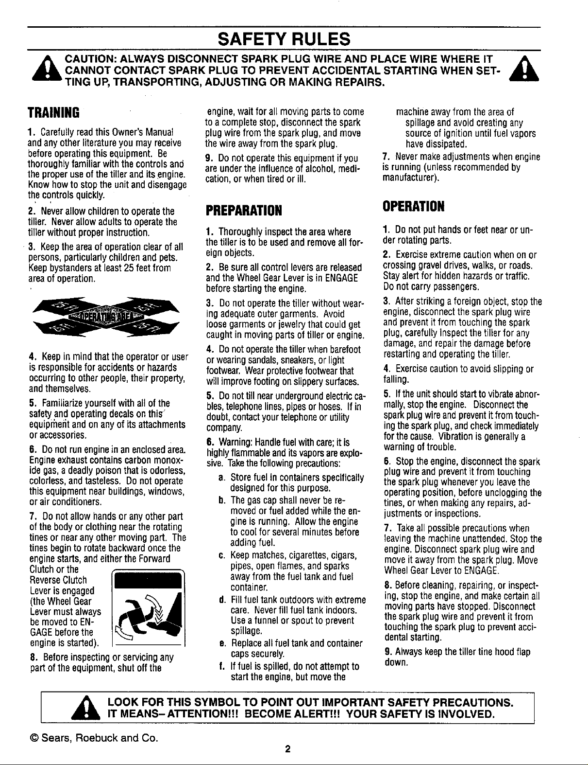
7. Do not allow handsor anyother part
of the body or clothing nearthe rotating
tines or nearany other moving part. The
tines beginto rotate backward oncethe
engine starts, andeitherthe Forward
Clutchor the
ReverseClutch
Leveris engaged
(theWheelGear
Levermustalways
be moved to EN-
GAGEbeforethe
engine is started).
8. Beforeinspectingor servicing any
partof the equipment, shut offthe
engine,wait for all moving parts to come
to a complete stop, disconnect the spark
plug wire from the sparkplug, and move
the wire awayfrom the spark plug.
g. Donot operate this equipment if you
are under the influence of alcohol, medi-
cation,or whentired or ill.
PREPARATION
1. Thoroughly inspect the areawhere
the tiller is to beusedand remove all for-
eign objects.
2. Besure all control levers are released
andthe Wheel GearLever isin ENGAGE
beforestarting the engine.
3. Donot operate the tiller without wear-
ing adequateouter garments. Avoid
loose garmentsor jewelry that could get
caught in moving parts of tiller or engine.
4. Donot operatethetiller when barefoot
orwearingsandals,sneakers,or light
footwear. Wearprotectivefootwearthat
will improve footing on slippery surfaces.
5. Do nottill nearundergroundelectricca-
bles,telephonelines,pipesor hoses. If in
doubt, contactyour telephoneor utility
company.
6. Warning:Handlefuel with care;it is
highlyflammable and itsvaporsareexplo-
sive. Takethefollowing precautions:
a. Store fuel in containersspecifically
designedfor this purpose.
b. Thegas capshall neverbe re-
moved or fuel addedwhile the en-
gine is running. Allow the engine
to coo[ for several minutes before
adding fuel.
c. Keepmatches,cigarettes,cigars,
pipes, open flames, and sparks
awayfrom thefuel tank andfuel
container.
d. Fillfuel tank outdoors with extreme
care. Neverfill fuel tank indoors.
Use afunnel or spout to prevent
spillage.
e. Replaceall fuel tank and container
capssecurely.
f. Iffuel is spilled, do not attempt to
start the engine,but move the
machineawayfrom the areaof
spillage andavoid creatingany
source of ignition until fuel vapors
havedissipated.
7. Nevermakeadjustmentswhenengine
is running (unlessrecommendedby
manufacturer).
OPERATION
1. Donot put handsor feet nearor un-
der rotating parts.
2. Exerciseextreme cautionwhen on or
crossing gravel drives, walks, or roads.
Stay alert for hidden hazardsor traffic.
Do not carry passengers.
3. After striking aforeign object, stopthe
engine,disconnect the spark plug wire
and prevent it from touching the spark
plug, carefully inspect thetiller for any
damage,and repairthe damagebefore
restarting and operatLngthe tiller.
4. Exercisecaution to avoid slipping or
falling.
5. If the unit shouldstartto vibrateabnor-
mally,stop theengine. Disconnectthe
spark plug wireand preventit from touch-
ingthe sparkplug, andcheck immediately
for the cause.Vibration is generallya
warning of trouble.
6. Stop the engine, disconnect the spark
plug wire and prevent it from touching
the spark plug wheneveryou leavethe
operating position, before unclogging the
tines, or when making any repairs, ad-
justments or inspections.
7. Takeall possibleprecautionswhen
leavingthe machineunattended.Stopthe
engine.Disconnect spark plug wire and
move it awayfrom the sparkplug. Move
WheelGearLeverto ENGAGE.
8. Beforecleaning,repairing, or inspect-
ing,stop the engine, and makecertain all
moving parts havestopped. Disconnect
the spark plug wire and preventit from
touching the spark plug to preventacci-
dentalstarting.
9. Always keepthe tiller tine hood flap
down.
LOOK FOR THIS SYMBOL TO POINT OUT IMPORTANT SAFETY PRECAUTIONS.
IT MEANS-ATTENTIONH[ BECOME ALERTIH YOUR SAFETY IS INVOLVED.
© Sears, Roebuck and Co.
2

SAFETY RULES
10. Neveruse the tiller unlessproper
guards,plates,or othersafetyprotective
devicesareinplace.
11. Do not run engine in an enclosed
area.Engineexhaustcontains carbon
monoxide gas,a deadly poison that is
odorless, colorless, and tasteless.
1;'. Keepchildrenand petsaway.
13. Neveroperatethe tiller under engine
power if the WheelGearLeveris in
DISENGAGE(FREEWHEEL).In this posi-
tion, the wheelswill not hold the tiller
back and the revolving tines could propel
the tiller rapidly backward,possibly caus-
ing loss of control. Always move the
WheelGearLeverto ENGAGEbefore
•starting the engine or engaging the
tines/wheels with the Forward Clutch or
the ReverseClutch.
14. Beawarethattheti_lermayunex-
pectedlybounce upwardor jump back-
ward if thetines should strike extremely
hard packedsoil, frozenground, or
buried obstacleslike largestones, roots,
Qrstumps. If in doubt about the tilling
conditions, always use the following op-
erating precautionsto assist you in main-
taining control of the tiller:
a. Walk behind and to one side of the
.,, tilier,,using onehand on the han-
dlebars. Relaxyour arm, but use a
secure hand grip.
b. Useslower engine speeds.
c. Clearthe tilling area of all large
stones, roots and other debris.
d. Avoid using downward pressure on
handlebars. If needbe, useslight
upward pressure to keepthe tines
..... from digging too deeply.
• e. In an emergency,stoptines and
wheels by releasingwhichever
ClutchLeveris engaged.Do not
attemptto restrainthe tiller.
15. Do not overloadthe tiller's capacity
by attemptingto till too deeplyattoo fast
a rate.
16. Never operatethetillerat high trans-
portspeeds on hard or slippery surfaces,
Lookbehindand usecarewhenbacking
up.
17. Donot operatethe tilleron a slope
thatistoo steepfor safety.Whenon
slopes,slowdownand makesureyou
havegoodfooting. Neverpermitthetiller
to freewheeldownslopes.
18. Neverallowbystandersnearthe
unit.
19. Only useattachmentsandacces-
soriesthat are approvedby thetiller
manufacturer.
20. Usetiller attachmentsand acces-
sories when recommended.
21. Neveroperatethe tiller without good
visibilityor light.
22. Neveroperatethetiller ifyou aretired,
or underthe influenceof alcohol,drugsor
medication.
23. Operatorsshallnot tamperwiththe
engine-governorsettingsonthemachine;
thegovernorcontrols the maximumsafe
operatingspeedto protectthe engineand
all moving partsfrom damagecausedby
overspeed.Authorizedserviceshall be
sought ifa problemexists.
24. Do not touch enginepartswhich may
behotfrom operation.Letpartscooldown
sufficiently.
25. Pleaseremember:Youcanalways
stopthetines andwheelsbyreleasingthe
ForwardClutchLeveror theReverseClutch
Lever(whicheverleveryou haveengaged)
or bymovingthe Throttle ControlLeverto
STOP.
26. To loador unloadthe tiller, seethein-
structionsinthisManual.
27. Useextremecautionwhenreversing
or pullingthemachinetowardsyou.
28. Startthe enginecarefullyaccordingto
instructionsandwith feetwellawayfrom
thetines.
29. Neverpickupor carrya machinewhile
theengineisrunning.
MAINTENANCE/STORAGE
1. Keepthe tiller,attachments andacces-
sories insafe workingcondition.
2. Checkall nuts, bolts, andscrews at
frequent intervalsfor propertightness to
besure the equipmentis in safeworking
condition.
3. Neverstorethetillerwith fuel inthe fuel
tank insidea buildingwhereignition
sourcesarepresent(suchashot waterand
spaceheaters,furnaces,clothesdryers,
stoves,electricmotors, etc.). Allowengine
to coolbeforestoring in anyenclosure.
4. Toreducethechancesof afire hazard,
keepthe enginefreeof grass,leaves,or
excessivegrease.
5. Storegasolineina cool,well-ventilat-
edarea,safelyawayfrom anyspark-or
flame-producing equipment.Store gaso-
lineinanapprovedcontainer,safelyaway
from the reachofchildren.
6. Referto the ServiceandAdjustments
Section of this Manualif thetiller is to be
stored for anextendedperiod.
7. Neverperform maintenancewhile the
engine is runningor thespark plugwire is
connected,exceptwhen specificallyin-
structed to do so.
8. If the fuel tank has to bedrained,do
this outdoors.
TOAVOIDINJURY:
• READOWNER'SMANUAL.
• KNOW LOCATION AND
FUNCTION OF ALL CON-
TROLS.
• KEEPALL SAFETYDEVICES
AND SHIELDS IN PLACE
ANDWORKING,
• NEVER ALLOW CHILDREN
ORUNINSTRUCTEDADULTS
TOOPERATETILLER.
• SHUT OFF ENGINE AND
DISCONNECTSPARKPLUG
WIRE BEFORE UNCLOG-
GING TINES OR MAKING
REPAIRS.
• KEEPBYSTANDERSAWAY
FROMMACHINE,
• KEEPAWAYFROM ROTAT-
INGPARTS.
• USE EXTREME CAUTION
WHEN REVERSING OR
PULLINGTHE MACHINETO-
WARDSYOU.
WARNING:
The engine exhaust from this
product contains chemica!s
knownto the StateofCaliformai
to cause cancer, birth defects,i
orotherreproductiveharm.

CONGRATULATIONS on your purchase of a Sears
Craftsman tiller. It has been designed, engineered and
manufactured to give you the best possible dependability
and performance.
Should you experience any problems you cannot easily
remedy,please contact your nearest Sears Service Cen-
ter/Department. We have competent, well-trained tech-
nicians and the proper tools to service or repair this
machine.
Please read and retain this manual. The instructions will
help you assemble and maintain your machine properly.
Always observe the "SAFETY RULES."
MODEL NUMBER: 987.293330
SERIAL
NUMBER:
DATE OF
PURCHASE:
THE MODELAND SERIAL NUMBERS WILL BE
FOUND ON A DECAL LOCATED ON THE TRANS-
MISSION OF YOUR MACHINE.
YOU SHOULD RECORD BOTH THE SERIAL NUM-
BER AND DATE OF PURCHASE AND KEEP IN A
SAFE PLACE FOR FUTURE REFERENCE.
MAINTENANCEAGREEMENT
A Sears maintenance agreement is available on this
product. Contact your nearest Sears store for details.
CUSTOMERRESPONSIBILITIES
O Read and observe the safety rules.
O Follow a regular schedule in maintaining, caring for
and using this product.
[] Follow the instructions under "CUSTOMER
RESPONSIBILITIES" and "STORAGE" sections of
this manual.
PRODUCTSPECIFICATIONS
HORSEPOWER: 8 HP
DISPLACEMENT: 19.43 CU. iN.
FUEL CAPACITY: 2 Quarts
SPARK PLUG (GAP 0.030-in.): Champion RJ-17LM*
or equivalent
IGNITION: Electronic
NET ENGINE WEIGHT: 50 LBS.
NET TILLER WEIGHT: 204 LBS.
• InCanada, replacespark plugwitha resistorplug.
WARNING
This machine is equipped with an internal combus-
tion engine and shouldnot be used onor near any
unimproved forest-covered, brush-covered or
grass-covered land unless the engine's exhaust
system is equipped with a spark arresfer meeting
applicable local or state laws (if any). If a spark
arrester is used, it should be maintained in
effective workingorder bythe operator.
In the state of California the above is required by
law (Section 4442 of the California Public
Resources Code). Other states may have similar
laws. Federal laws apply on federal lands. This
engine is not equippedwith a spark arrestor for the
muffler. Asparkarrester for the muffler is
available through your nearest Sears authorized
service center. See the REPAIR PARTSsection of
this manual.
*,
LIMITEDTWO-YEARWARRANTYONCRAFTSMAN®TILLER
Fortwo years from the dateof purchase,when this Craftsman®Tiller ismaintained,lubricated, and tuned up according to the
operating maintenanceinstructions in the owner's manual,Searswill repair,free of charge,anydefect in material or
workmanship.
Ifthis Craftsman®Tilleris usedfor commercialor rental purposes, thiswarrantyappliesfor only90 daysfrom the dateof
purchase.
THISWARRANTYDOESNOTCOVER:
• Expendableitems whichbecomewornduringnormaluse,suchastJQ.P,.(._,belts,soarkglue, andair cleaner.
• Repairsnecessarybecauseofoperatorabuseornegligenceincludingbentcrankshaftsandthefailureto maintain the
equipmentaccordingtotheinstructionscontainedintheowner'smanual.
WARRANTYSERVICEISAVAILABLEBYRETURNINGTHECRAFTSMAN@TILLERTOTHENEARESTSEARSSERVICECENTERIN
THEUNITEDSTATES.THISWARRANTYAPPLIESONLYWHILETHISPRODUCTISIN USEINTHEUNITEDSTATES.
Thiswarrantygivesyou specificlegalrights,andyou mayalso haveotherrightswhichvaryfrom stateto state.
Sears, Roebuck and Co., D/817WA, Hoffman Estates, IL 60179
4

TABLE OF CONTENTS
SAFETY RULES ................................................... 2
PRODUCT SPECIFICATIONS .............................. 4
WARRANTY .......................................................... 4
ACCESSORIES .................................................... 6
CONTENTS OF HARDWARE PACKAGE ............ 7
ASSEMBLY ........................................................... 8
OPEI_ATION ....................................................... 12
CUSTOMER RESPONSIBILITIES ..................... 22
INDEX
ii
SERVICE AND ADJUSTMENTS ........................ 26
STORAGE ........................................................... 32
TROUBLESHOOTING ........................................ 33
DECALS .............................................................. 34
REPAIR PARTS - TILLER .................................. 35
REPAIR PARTS - ENGINE: .................... ............ 50
PARTS ORDERING/SERVICE ........... Back Cover
A
Accessories .................. 6
Air Cleaner Maintenance ....... 25
Assembly .................... 8
B
Break-In Operation ........... 16
Belt Tension Adjustment ....... 28
Belt Removal and Replacement , 30
C
Carburetor .................. 25
Changing Engine Oil .......... 24
Changing Transmission Oil ..... 24
Checking/Adding Engine Oil .... 24
Checking/Adding Transmission Oil 24
Checking/Adjusting Belt Tension. 28
Checking for Oil Leaks ......... 23
Check List, Pre-Starting ........ 15
Cleaning .................... 25
Cooling System Maintenance... 25
Controls .................... 12
D
Decals ..................... 34
Depth Regulator Lever ........ 14
E
Engine
Air Filter .................. 25
Carburetor ................ 25
Choke Lever ............... 15
Cooling System ............ 25
Fuel Tank ................. 16
Oil, Checking/Adding ........ 24
O_5_rat'ion.... _............ 16
Parts ..................... 50
Recoil Start Rope ........... 15
Spark Plug ................ 25
Speed .................... 15
Starting Engine ............. 16
Stopping Engine ............ 16
Storage ................... 32
Throttle Lever ........... 10,15
F
Features/Controls ............ 12
Forward Clutch ............. 9,13
Forward Travel ............... 17
Fuel Tank ................... 16
G
Guiding the Tiller ............. 17
il
Handlebar Height Adjustment . .8,14
Hardware .................... 7
Leaks, Oil ................... 23
Loading and Unloading Tiller .... 21
Location of Controls ........... 12
Lubrication .................. 23
M
Maintenance Schedule ........ 22
Maintenance Agreement ........ 4
Model/Serial Number ........... 4
Motor Oil, Adding .......... 15, 24
Motor Oil, Changing ........... 24
0
Oil ...................... 15
Off-Season Storage ........... 32
Operation ................... 17
P
Parts List ................... 35
Pre-Start Checklist ............ 15
Product Specifications .......... 4
R
Reverse Clutch .............. 13
Reverse Travel .............. 18
Recoil Starter Rope ........... 15
Repair Parts ................. 35
5
S
Safety Rules ................. 2
Safety Decals ............... 34
Seedbed Preparation .......... 19
Service Recommendation
Checklist ................. 22
Slopes ..................... 20
Spark Plug .................. 25
Starter Rope ................ 15
Storage .................... 32
T
Tiller Parts .................. 35
Tilling ...................... 17
Tilling Depths ................ 19
Tine Cleaning ................ 20
Tine Removal ................ 26
Transmission Gear Oil ......... 24
Troubleshooting .............. 33
Turning Around .............. 18
II
Unpacking ................... 8
Untangling Tines ............. 20
W
Warranty .................... 4
Wheel Gear Lever ............ 12
Wheel Gear Cable Adjustment . .26
RIGHT
SIDE
OPERATOR'S
POSITION
LEFT
FORWARD SIDE
OPERATOR'S POSITION
All references to LEFT and
RIGHT sides of the tiller are
given from the operator's posi-
tion behind the handlebars (un-
less specified otherwise).

ACCESSORIES
These accessories were available when the tiller was purchased. They are available at most Sears retail
outlets, catalog and service centers. Most Sears stores can order repair parts for you when you provide the
model number of your tiller.
ACCESSORIES
"'Figure 1-1
Spark Plug GasCan
Motor Oil
COMPONENTS REQUIRING ASSEMBLY
REVERSE
CLUTCHROD
ENGINE
LEVER
FORWARD
CLUTCHROD
HANDLEBARS
WHEEL
Figure1-2
6

10
©©
©©
CONTENTS OF HARDWARE PACK
Hardware packed in carton
2
Figure1.3
Ref. No,
1
2
3
4
5
6
7
8
9
10
11
12
13
Hardware Description Qty.
Height Adjustment Handle (for handlebar) ........... 1
Keyed Washer (for height adjustment handle) ..... 1
Plastic Tie Strap ................................................... 4
Hairpin Cotter ....................................................... 3
3/8"-16 1"Hex Hd. Screw .................................... 2
3/8" Flat Washer .................................................. 2
3/8"-16 Nylok Lock Nuts ...................................... 2
Throttle Lever Knob ............................................. 1
#10-32 x 1/2" Round Hd. Screw .......................... 4
#10 Lockwasher ................................................... 4
#10-32 Nut ........................................................... 4
Wheel Gear Lever Knob ...................................... 1
5/16" Flat Washer .................................................. 1
T00LS/MATERIALS
NEEDEDFOR ASSEMBLY
(1) * 3/8" open end wrench
(2) * 9/16" open end wrenches
(1) Scissors (to trim plastic ties)
(1) Ruler
(1) Small Board (to tap plastic
knobs on control levers)
(1) Automotive-type air pressure
gauge
(1) Clean Oil Funnel
(1) Clean high-quality engine oil.
Refer to the assembly instruc-
tions in this manual for engine
oil specifications and quantity
required. Do not overfill.
•Adjustable wrenchesmay be used.
IMPORTANT: Motor oil must be
added to the engine crankcase be-
fore the engine is started. Follow the
instructionsin the "Operation" section.
11,
7

ASSEMBLY
Read these instructions completely
before you attempt to assemble or
operate your new equipment. Your
tiller has been assembled at the fac-
tory with the exception of those parts
left'unassembled for shipping pur-
poses. Steps in this section show
you how to assemble them. To en-
sure safe and proper operation of
your machine, all parts and hard-
ware you install or adjust must be
tightened securely. Use the correct
tools as necessary to ensure proper
tightness.
UNPACKINGINSTRUCTIONS
• Inspect your machine immediately.
Be sure neither the carton nor con-
tents have been damaged. If you
'.find or have reason to suspect
damage, contact the nearest
Sears Service Center for
assistance.
• Once the cardboard shipping car-
ton is open, remove any packing
material from around the machine.
Remove any staples securing bot-
tom of carton to wood pallet. Lift
.,off carton. Before disposing of the
carton or any of the packing mate-
rials, be sure to check them thor-
oughly for any small parts.
Leave unit on base of pallet dur-
ing assembly steps (to safely re-
move unit from pallet, wait until
you have installed the handlebar
assembly and the Wheel Gear
Lever is placed in DISENGAGE).
The procedure for removing the
tiller isexplained in Step 1, item 6
of these assembly steps.
• Also remove any packaging around
the handlebar.
• Perform the assembly on a clean,
level surface. If you need to move
the machine, be careful not to
severely bend any of the control
cables on the equipment.
• Remove the handlebar assembly
from the carton. Do not remove
the two control levers from the
' handlebars.
• A plastic bag inside the literature
envelope contains loose hardware.
Open the bag and check the con-
tents against the hardware list on
Page 7 and the hardware shown in
Figure 1-3.
ASSEMBLYSTEPS
STEP 1: Attach the Handlebars
1. Remove the Reverse Clutch
Lever (B, Figure 2-1) from the han-
dlebars (A). Remove any rubber
bands from the handlebars.
2. Position the handlebar cross-
brace (C, Figure 2-2) in front of the
curved height adjustment bracket (D)
and place the handlebar ends to the
outside of the two mounting tabs on
top of the transmission.
3, Attach the handlebars to the
mounting tabs with two 3/8-16 x 1"
screws (heads of screws go to inside
of tabs), 3/8" flat washers and 3/8"-
16 Nylok lock nuts (see Figure 2-2).
Do not fully tighten the screws at this
time.
4. Move the handlebar to align the
hole in the cross-brace with one of
the four slots in the curved height
adjustment bracket. Place the keyed
washer (E, Figure 2-3) on the height
adjustment handle (F) with the
raised keys (edges) on the keyed
washer facing down.
5. Screw the height adjustment han-
dle (F) into the threaded hole in the
handlebar cross-brace, making sure
that the raised keys on the washer fit
into the selected slot on the curved
bracket. Tighten the height adjust-
ment handle securely. Next, secure-
ly tighten the two screws that attach
the handlebar ends to the mounting
tabs (Figure 2-2).
6. To remove the tiller from its ship-
ping platform, free the wheels by
moving the Wheel Gear Lever (G,
Figure 2-4) to the DISENGAGE posi-
tion (this allows the wheels to ro-
tate). Carefully unwrap the wheel
gear cable from around the unit be-
fore moving the lever. Use this DIS-
ENGAGE mode only when the en-
gine is not running. Before starting
the engine, the Wheel Gear Lever
must be placed in the ENGAGE po-
sition (see the "Operation" section
for details).
Figure2.1: RemoveReverseClutchLever.
D
Figure2-2: Attachhandlebars.,
E F
Figure2-3:Installheightadjustmenthandle.
Figure2-4:PutWheelGearLeverIn
DISENGAGEposition.

ASSEMBLY
STEP2: Attach ReverseClutch
Lever
1. Slide the Reverse Clutch Lever
(removed in Step 1) down through
the hole in the left side of the handle-
bar control panel and pass it above
the cross-brace at the lower end of
the handlebar.
2. Insert the end of the lever (I, Fig-
ure 2-5) through the hole in the pivot
(J). Note that there are two small
holes in the lower end of the lever.
3. Install a 5/16" flat washer (K) and
secure it with a hairpin cotter (L)
throughthe bottom hole in the lever.
Figure2-5:InstaNReverseClutchLever.
IMPORTANT: If the handlebar is ad-
justed to the highest position, then
the bottq_mof the Reverse Clutch
Lever must be secured with the hair-
pin cotter (L) through the top hole in
the lever. Simply remove the hairpin
cotter, slide the washer (K) up the
lever, and replace the hairpin cotter.
STEP3: Attach ForwardClutchRod
1. The upper end of the Forward
Clutch rod is attached to the bottom
of the handlebar control panel. Turn
the rod (M, Figure 2-6) so the small
bend at its lower end points inward.
2. Insert a hairpin cotter down
through the hole located closest to
the bend (see Figure 2-6).
3. There are four numbered holes in
the i_ldtchswivel plate (see Figure 2-
7) and four numbered slots in the
curved height adjustment bracket.
For correct operation of the Forward
Clutch rod, the numbered hole used
for the Forward Clutch rod must
match with the numbered slot in the
height adjustment bracket. For ex-
ample, if the handlebar is set in slot
#1, then the Forward Clutch rod
must be installed in hole #1 of the
clutch swivel plate.
IMPORTANT: Whenever the handle-
bar heightischanged, the hole posi-
tion of the Forward Clutch rod must
be changed accordingly. Changing
the handlebar height changes the
tension on the Forward Clutch rod -
this tension must be adjusted by
relocating the rod in the appropriate
hole in the clutch swivel plate.
4. Select the proper hole in the
clutch swivel plate and insert the
Forward Clutch rod so that the tip
faces inward (see Figure 2-7). Se-
cure the rod by inserting a second
hairpin cotter through the hole near
the tip of the rod.
5. Check for correct tension on the
Forward Clutch rod as follows:
(a) There are two interconnected
Forward Clutch paddles that
hang beneath the control panel.
Lift and hold the right-side paddle
against the handlebar grip.
(b) While squeezing the paddle,
measure the gap between the E-
ring and the lower end of the
clutch rod bracket (see Figure 2-
8). The gap should be 3/16"-to-
5/16". NOTE: A stack of 5 pen-
nies is approximately 5/16" thick.
(c) If the gap is incorrect:
(1) First check that the Forward
Clutch rod is in the correct
hole in the clutch swivel plate.
If not, reposition the rod and
repeat Step 5b.
(2) If the Forward Clutch rod is in
the correct hole and the gap is
incorrect, you will need to ad-
just the length of the Forward
Clutch rod. To do this, first re-
lease the Forward Clutch pad-
dle and then disconnect the
rod from the clutch swivel
plate (remove hairpin cotter at
end of rod and pull rod out of
hole in clutch swivel plate).
If the gap is more than 5/16",
rotate the rod counterclock-
wise (as viewed from the front
of tiller) to decrease the gap.
Reinstall the rod in the correct
clutch swivel plate hole, se-
cure it with the hairpin cotter,
and repeat Steps 5a and 5b.
If the gap is less than 3/16",
rotate the rod clockwise (as
viewed from the front of tiller)
to increase the gap. Reinstall
the rod in the correct clutch
swivel plate hole, secure it
with the hairpin cotter, and re-
peat Steps 5a and 5b.
Figure2-6: Install ForwardClutchrod.
Figure2-7:Numberedsettingsforhandle-
barheightslotsandclutchswivelplate
holes.
Gapshouldbej
3/16"-to-5/'16"
Figure2-8. WhilesqueezingForward
Clutchpaddle,measuregapbetweenend
ofbracketandE.ring.
9

STEP4: CheckGearOilLevelin
TranS'm[ssion
The transmission was filled with gear
oil at the factory. However, be sure
to check the oil level at this time.
1. Move the tiller to a level area.
2. Pull the Depth Regulator Lever
(N, Figure 2-9) straight back and
then slide it to the second notch from
the top. If the lever does not move
freely, lift the tine hood flap and look
for a plastic tie securing the lever in
place. Cut and remove the tie.
3. Remove the oil level check plug
(O, Figure 2-10) on the left-side of
the transmission. (Due to dried paint
on the plug threads, it may require
some force to remove the plug the
first time.) The gear oil level is cor-
rect if oil starts to flow out of the hole
as the plug is removed. If so, se-
curely reinstall the plug.
4. If oil does not flow from the check
hole, add SAE 140, SAE 85W-140 or
SAE 80W-90 weight gear oil (prefer-
ably use API rated GL-4 gear oil,
however GL-5 can be used for small
top-offs) as follows:
NOTE: Do not use automatic trans-
mission fluid or engine oil in the
transmission.
(a) Clean area around oil fill hole (P,
,,.Figure,2-11) and unscrew oil fill
plug.
(b) Using a clean funnel, slowly add
gear oil until itflows from the oil
level check hole (O, Figure 2-10).
Securely reinstall the oil level
check plug (O).
(c) Reinstall and tighten the oil fill
plug.
Figure2.9: PutleverInsecondnotch.
ASSEMBLY
Figure2.10: Gearoillevelcheckplug.
Figure2-11: Addinggearoilin o/Ifill hole.
STEP5: AttachThrottle Lever
For shipping purposes, the engine
throttle cable assembly is wrapped
around the engine. Carefully unwrap
the cable and attach it as follows:
1. Route the throttle cable up the
right-side handlebar. Insert its lever
(R, Figure 2-12) up through the slot
in the control panel labeled "ENGINE
THROTTLE."
2. Insert two #10-32 x 1/2" round
head screws down through the "+"
marks on the control panel decal and
through the holes in the base of the
engine throttle lever.
3. Hold the engine throttle lever
base against the bottom of the con-
trol panel and secure it with two #10
Iockwashers and #10-32 nuts.
4. Place the "T" shaped engine
throttle lever knob on the end of the
lever. Use a board to tap knob until it
seats firmly on lever (Figure 2-12).
5. Move the lever forward and back-
ward - it should move freely through
the full range of travel. (Note that
there is a detent at the SLOW setting
Figure2.12:Attachenginethrottlelever.
which catches the lever. This detent
prevents the lever from unintention-
ally moving to the STOP setting
when you are just trying to slow the
engine down.) If the lever is difficult
to move away from the STOP set-
ting, loosen both screws and move
the lever assembly slightly to the left.
Retighten screws and recheck move-
ment. Adjust the lever as needed.
6. Secure the throttle cable to the
right-side handlebar with two plastic
ties (S, Figure 2-13) located about
two feet apart. The serrated side of
the tie must be on the inside of the
loop. Trim tie length with scissors.
STEP6: AttachWheelGearLever
For shipping purposes, the wheel
gear cable is wrapped around the
transmission. Carefully unwrap the
cable and attach it as follows:
1. Route the wheel gear cable up
the left-side handlebar and insert the
lever (T, Figure 2-14) up through the
slot in the control panel that is la-
beled "WHEEL GEAR."
2. Insert two #10-32 x 1/2" round
head screws down through the "+"
marks on the control panel decal and
through the holes in the base of the
wheel gear lever. '....
3. Hold the wheel gear lever base
against the bottom of the control
panel and secure it with two #10
Iockwashers and #10-32 nuts.
4. Place the wheel gear lever knob
on the end of the lever and use a
board to tap the knob down until it
seats firmly on the lever (see Figure
2-14).
5. Secure the cable to the left-side
handlebar with two plastic ties (U,
Figure 2-13) located about two feet
apart. Snip off any excess tie length
with scissors.
10

,, ASSEMBLY
STEP7: CheckAir Pressurein
Tires
S
.Figure2.13. Attachthrottle cable withplas-
tic ties (S). Attach wheel gear cable with
plastic ties (U).
Use an automotive-type tire pressure
gauge to check the air pressure in
both tires. Deflate or inflate both
tires evenly from 15-to-20 PSI
(pounds per square inch). Be sure
that both tires have the same air
pressure or the unit witl pull to one
side.
STEP8 : CheckHardwarefor
Tightness
Inspect the hardware on the unit and
tighten any loose screws, bolts and
nuts.
IMPORTANT" Motor oil must be
added to the engine crankcase
before the engine is started.
Follow the instructions in the
"Operation" section.
Figure2-14: Attachwheelgearlever.
CAUTION
Unit is shipped without oil in
engine crankcase. DO NOT
start engine until oll has been
added. Severe enginedamage
will result if this instruction is
net followed. See "Operation"
Section in this manual for oil
filling procedure.
11

OPERATION
KNOWYOURTILLER
READ THIS OWNER'S MANUALAND ALL SAFETY RULES BEFORE OPERATING THIS EQUIPMENT. Know the lo-
cation and function of all features and controls on the equipment. Save this manual for future reference.
ReverseClutch
MEETS ANSI B71.8 - 1996
SAFETY STANDARD
This machine meets voluntary safety
standard B71.8 - 1996, which is
sponsored by the Outdoor Power
Equipment Institute, Inc., and is pub-
lished by the American National
Standards Institute, Inc.
Operating Symbols
Varioussymbols are used on the tiller
toindicatecontrolsettings(your model
may not have all of the symbols).
These symbols are shown belowwith
a descriptionoftheirmeaning.
HandlebarHeight
Adjustment
ChokeControl
Recoil
Wheel G'ear
_Lever
ForwardClutch
(on eachside)
FAST SLOW CHOKE
ENGINE ENGINE ENGINE
STOP START RUN
z2.r
ENGAGE DISENGAGE
ROTATING TILLER
TINES DIRECTION
ip,
o--->
LEVER
STOP DIRECTION
..... N R
NEUTRAL REVERSE
LOCATIONANDUSEOFTILLERCONTROLS
WheelGearLever
This lever (A, Figure 3-1) has two
operating positions: ENGAGE and
DISENGAGE.
In the ENGAGE position, the wheels
will start turning when either the
Forward Clutch or the Reverse
Clutch is engaged (the tines will also
start turning when either clutch is
engaged).
The DISENGAGE position places
the wheels in the freewheeling mode
to allow the unit to be moved without
the engine running. Use the DISEN-
GAGE position only when the engine
is not running. See "DANGER"
statement that follows.
To shift to ENGAGE, gently (do not
force) move the lever forward while
also rolling the tiller a few inches for-
ward or backward. (Moving the tiller
helps to align the shift mechanism
with the transmission wheel drive
gears.) The wheels will not free-
wheel when the lever is properly set
in the ENGAGE position.
To shift to DISENGAGE (freewheel)
simply move the lever, rearward,
without rolling the tiller. The wheels
will roll freely when the lever is prop-
erly set in the DISENGAGE position.
12
Figure3-1:WheelGearLever.
DANGER
Never place the Wheel Gear
Lever in DISENGAGE (Free-
wheel) when the engine is run-
ning.
Having the Wheel Gear Lever
in DISENGAGE and then en-
gaging the tines/wheels with
either the Forward Clutch or
the Reverse Clutchcould allow
the tines to propel the tiller
rapidly backward.
Failure to follow this instruc-
tion could result in personal
injury or property damage:

' ' OPERATION
ForwardClutch
The two interconnected levers (B,
Figure 3-2) control the engagement
of forward drive to the wheels and
power to the tines.
To Operatethe ForwardClutch:
1, Before engaging the Forward
Clutch, put the Wheel Gear Lever in
the ENGAGE position (sea "WARN-
ING" below).
2_, Lift and hold one or both of the
levers against the handlebar grips to
engage the wheels and tines.
3. Release BOTH levers to disen-
gage the wheels and tines. All for-
ward motion will stop (the engine will
continue to run).
WARNING
Never engage the wheels and
tines with the Forward Clutch
or the Reverse Clutch unless
the Wheel Gear Lever is in
ENGAGE.
Engaging the Forward Clutch
or the ReverseClutchwhen the
wheels are not engaged could
allow the tines to rapidly pro-
pe] the tiller forward or
backward.
Failure to follow this warning
could result in personal injury
or propertydamage.
IMPORTANT: The Forward Clutch
Levers are connected to a mechani-
cal interlock feature that automatical-
ly shifts the separate Wheel Gear
Lever (A, Figure 3-1) into ENGAGE
position when either of the Forward
Clutch Levers is lifted up against the
handlebars to engage power to the
wheels and tines. This is a safety
feature designed to prevent the
wheels from being in DISENGAGE
(freewheel) position when the tines
are rotating.
Before starting the engine, test
the function of the mechanical inter-
lock as follows:
.
Put the Wheel Gear Lever in
the DISENGAGE position and
roll the tiller back and forth a
few inches. The wheels
should roll freely.
o
At rest, squeeze either of the
Forward Clutch Levers ("pad-
dles") against the handlebar
grips. As the "paddles" move
upward, the mechanical inter-
lock will automatically move
the Wheel Gear Lever forward
into the ENGAGE position.
(Roll the tiller back and forth a
few inches.) If it does, the tiller
wheels will not roll freely when
you push and pull on the han-
dlebars.
. The mechanical interlock is
working properly if it performed
as described in step 2. If the
mechanical interlock did not
perform correctly, do not oper-
ate the tiller until it has been
inspected and corrected by
your Sears Service Center.
ReverseClutch
This lever (C, Figure 3-3) controls
the engagement of reverse drive to
the wheels and tines. It is the only
control that provides reverse direc-
tion of the wheels and tines.
ToOperatethe ReverseClutch:
1. Before engaging the Reverse
Clutch, put the Wheel Gear Lever in
ENGAGE (see "WARNING" state-
ment on this page).
2. Release the Forward Clutch
levers.
3. To move the tiller in reverse, first
stop all forward motion. Then lift up
the handlebars until the tines clear
the ground and pull the Reverse
Clutch lever out. The tines and
wheels will rotate in a reverse direc-
tion as long as the lever is held in
REVERSE. To stop the wheel'S;_.nd'
tines, release the lever and it will re-
turn to NEUTRAL. Never attempt to
till while going in the reverse
direction.
WARNING
• Use extreme cautionwhen
reversing or pulling the ma-
chine toward you. Lookbe-
hind to avoid obstacles,
• Never attempt to till in
reverse.
Failure to follow this warning
could result in personal injury
or property damage.
B
Figure3-2".ForwardClutchlevers.
Figure3-3".ReverseClutchlever.
13

DepthRegulator
This lever (D, Figure 3-4) controls
the tilling depth of the tines. Pull the
lever straight back and slide it up or
down to engage the notched height
settings.
The highest notch (lever all the way
down) raises the tines approximately
1-1/2 inches off the ground. This
"travel" position allows the tiller to be
moved withoutthe tines digging into
the ground.
Moving the lever up increases the
tilling depth. The lowest notch al-
lows a tilling depth of approximately
sixto eight inches, depending on soil
conditions.
F_)rbest results, always begin tilling
at a shallow depth setting, then in-
crease the tilling depth. Further in-
formation on using the Depth Regu-
OPERATION
Figure3.4: DepthRegulatorLever.
later isfound in the "Operation" Sec-
tion of this manual.
WARNING
Always place the Depth Regu-
lator Lever in the "travel"
position before startingthe en-
gine. This position prevents
the tines from touching the
ground until you are ready to
begin tilling.
Failure to follow this warning
could result in personal injury
or property damage.
HandlebarHeightAdjustment
The handlebar height is adjustable to
four different settings. Set the han-
dlebar height to a comfortable set-
ting, but keep in mind that the han-
dlebar will be lower when the tines
are engaged in the soil.
WARNING
Whenever the handlebar
height is changed,the Forward
Clutch shift mechanism must
be readjusted.
When adjusting or checking
the Forward Clutch mecha-
nism, shut engine off, discon-
nect spark plug wire and pre-
vent it from touching the spark
plug.
Failure to follow this warning
could allow the Forward Clutch
mechanism to operate improp-
erly which could result in per-
sonal injury or property
damage.
IMPORTANT: If the handlebar is ad-
justed to the highest position, then
the bottom of the Reverse Clutch
Lever must be secured with the hair-
pin cotter (and washer) through the
top hole in the lever (see K and L) in
Figure 2-5, Page 9.
ToAdjustthe HandlebarHeight:
1. Stop the engine, wait for all parts
to stop moving and then disconnect
the spark plug wire.
2. Loosen the two screws at the
lower ends of the handlebar.
3. Loosen the height adjustment
handle (E, Figure 3-5) and pull the
keyed washer (F) free of the slots in
the curved height adjustment bracket.
4. Move the handlebars to the new
slot setting and insert the raised
keys on the keyed washer into the
slot. nghten the height adjustment
handle securely.
5. Retighten the two screws at the
ends of the handlebar.
6. Adjust the tension on the Forward
Clutch rod shift mechanism, as follows:
(a) Remove the inner hair pin cotter
from the end of the Forward
Clutch rod.
(b) There are four numbered holes in
the clutch swivel plate (see Fig-
ure 3-6) and four numbered slots
in the curved height adjustment
bracket. For correct operation of
the Forward Clutch mechanism,
the numbered hole used for the
Forward Clutch rod must match
the numbered slot in the height
adjustment bracket. Example: If
handlebar is in slot #4, put For-
ward Clutch rod in hole #4 of
clutch swivel plate.
Figure3.5: HeightAdjustinghandle(E).
Figure3.6: Handlebarheight slatsand
clutchswivulplate holes.
(c) Select the correct hole in the
clutch swivel plate and insert the
Forward Clutch rod (tip faces in-
ward). Secure the rod with the
hairpin cotter.
(d) Check for correct tension on the
Forward Clutch rodas described
in Step 5 of "Step 3: Attach For-
ward Clutch Rod" on page 9.
,., 14

OPERATION
ENGINECONTROLS
IMPORTANT: The engine is
equipped with a recoil starter, a han-
dlebar-mounted engine throttle lever,
and a choke control The locations
and functions of each of these con-
trols are described below.
RecoilStarter
The recoil starter (G, Figure 3-7) is
used to "pull-start" the engine.
Before pulling the recoil starter han-
dle, make sure there are no obsta-
cles behind you. See "Engine Start-
ing and Stopping" in this section for
detailed engine starting instructions.
EngineChoke Lever
The choke lever (H, Figure 3-7) al-
lows a richer air/gas mixture to make
starting a cold engine easier. There
BEFORESTARTINGENGINE
AddMot_)r011to Engine
The tiller is shipped without oil in the
engine. Permanent engine damage
will result if the engine is run without
oil.
1. Only use high quality detergent oil
with API service classification SF,
SG, SH, or SH/CD. Above 32OF,use
SAE 30; below 320F, use 5W30. Do
nat.use SAE 10W40 oil
) ,
[ colder.._----._- 32OF-.-----.._ warmer]
NOTE: Although multi-viscosity oils
(5W30, 10W30, etc.) improve start-
ing in cold weather, these oils will re-
sult inincreased oil consumption
when used above 32OF. Check
engine oil more frequently to avoid
possible engine damage from run-
ning low on oil.
5W30 I SAE30 ) ]/
are three settings: FULL
CHOKE, PARTIAL CHOKE
and NO CHOKE. Detailed in-
structions for using the choke
lever are provided later in this
section.
EngineThrottle Lever
The throttle lever (I, Inset to
Figure 3-7) is used to adjust
engine speed as well as stop
the engine.
Use the START position when
starting the engine. Use the
SLOW position when idling
the engine. Pull the lever all
the way back to the STOP po-
sition to turn the engine off.
Figure3-7:Enginecontrols--RecoilStarter(G);
ThrottleLever(H); ChokeLever(I).
Figure3-8:Addmotoroiltotheengineus.
ingtheoilfill tube(J).
2. With the tiller on level ground, pull
the Depth Regulator Lever (Figure
3-4) back and then all the way up
until the lowest notch in the lever is
engaged.
3. Unscrew the engine oil dipstick
(J, Figure 3-8) from the oil fill tube.
Using a clean funnel, slowly add oil
into the oil fill tube until the oil level
reaches the FULL mark reading on
the oil dipstick. While adding oil,
check the level several times with
the dipstick so as to avoid overfilling
the engine with oil. ALWAYS MAIN-
TAIN THE OIL LEVEL AT THE FULL
MARK.
4. Securely replace the oil dipstick.
IMPORTANT: Experience indicates
that alcohol-blended fuels (gasohol or
using ethanol or methanol) can at-
tract moisture which leads to separa-
tion and formation of acids during
storage. Acidic gas can dama_j_ the '
fuel system of an engine while in stor-
age. To avoid problems, the fuel sys-
tem should be emptied before stor-
age for 30 days or longer. Drain the
gas tank, start the engine and let it
run until the fuel lines and carburetor
are empty. Use fresh fuel next sea-
son. See STORAGE instructions for
additional information. Never use en-
gine or carburetor cleaner products in
the fuel tank or permanent damage
may occur.
Pre-StartChecklist
Move the tiller to a level area,
then make the following checks and
perform the following services before
starting the engine.
1. Disconnect Spark Plug Wire.
2. Add motor oil to engine. (Refer to
instructionson this page.)
3. Check the Air Cleaner. It must be
securely assembled and clean.
4. Check Safety Guards. All guards
and covers must be fastened securely.
5. Check Engine Cooling System.
The cooling fins and air intake
screen must be clear of debris.
6. Adjust Handlebar Height.
15
7, Put Gasoline in the Fuel Tank..
(Refer to instructionson next page.)
Use fresh, clean, unleaded regular
fuel. Fuel goes stale if stored for
more than six months. Do Not Mix
Oil With Gasoline!
8. Put Depth Regulator Lever in the
"travel" position.
9. Reconnect Spark Plug Wire.

Fill Fuel Tank
The engine must be off and cool be-
fore removing fuel fill cap (Figure 3-9).
Clean area around fuel fill cap and
then remove fill cap. Be sure to use
clean, fresh unleaded regular gaso-
line. Do not mix oil with gasoline.
NOTE: Do not use gasoline contain-
ing methanol (wood alcohol). Never
use stale gasoline left over from last
season or unused for long periods.
Using a funnel or spout, fill tank to
within 1/2" below the bottom of the
fuel tank filler neck to prevent spills
and to allow for fuel expansion. In-
stall the fill cap securely and wipe up
any spilled gasoline.
Figure3-9: Fill thefuel lank(K).
DANGER
Gasoline is highly flammable
and its vaporsexplosive. Fol-
low these safety practices to
prevent injury from fire or ex-
plosion:
• Never fill tank if engine is
runningor hot from use. Let
engine and mufflercooldown
beforerefueling.
• Do not permit open flames,
.sparks,matchesorsmokingin
fuelingarea.
• Fill fuel tank outdoors in a
well-ventilated area. Wipe
up any fuel spills and move
tiller awayfromfumes before
startingthe engine.
• Use only an approved fuel
container and lock it safely
away fromchildren.
• Store fuel and the tiller in a
well-ventilated area. Do not
store fuel or tiller where fuel
vapors may reach an open
flame or spark, or an ignition
source (a hot water heater,
furnace, clothes dryer, elec-
tric motor,orthe like).
• Let enginecoolbeforestoring.
OPERATION
ThrottleLever
HandlebarHeight
Adjustment
Choke
Control
Recoil
Starter
Figure3-I0
WARNING
Before operating your ma-
chine, carefully read and un-
derstand all Safety and Oper-
ation instructions in this Man-
ual and on the decals on the
machine.
Failure to .follow these in-
structions can result in seri-
ous personal injury.
STOPPINGAND
STARTINGTHEENGINE
Break-InOperation
Perform the following maintenance
during the first hours of new opera-
tion (see "Customer Responsibilities"
section of this manual).
1. Change engine oil after first 2
hours of new engine operation.
2. Check for loose or missing hard-
ware on unit. Tighten or replace as
needed.
StoppingtheEngine
The following steps describe how to
stop the engine.
1. To stop the wheels and tines, re-
lease the Forward Clutch levers or
the Reverse Clutch lever (whichever
control is in use).
16
ReverseClutch
2. To stop the engine, move the En-
gine Throttle Lever to the STOP
position.
WheelGear
J Lever
ForwardClutch
(oneachside)
Depth
Regulator
Startingthe Engine
The following steps describe how to
start the engine. Do not attempt to
engage the tines or wheels until
you have read all of the operating
instructions in this Section. Also
review the safety rules in the Safe-
ty Section.
1. Complete the '?re-Start Check-
list".
2. Put the Wheel Gear Lever (Figure
3-10) in the ENGAGE position.
3. Put the Depth Regulator Lever
(see Figure 3-10) in the "travel" posi-
tion (lever all the way down) so that
the tines are clear of the ground.
4. Release all controls on the tiller.
5. If engine is equipped with a fuel
shutoff valve, turn valve to the open
position.
6. Put the Engine Throttle Lever
(Figure 3-10) in the START setting.
7. Choke the engine (see Figure 3-
10) as follows: Move choke lever to
FULL CHOKE position (move in di-
rection of arrowhead located on
lever).
NOTE: If restarting a warm engine
after a short shutdown, move choke
lever to NO CHOKE position instead.

OPERATION
i,
CAUTION
To help prevent serious
personal injury or damage to
equipment:
• Before starting engine, put
Wheel GearLever in ENGAGE
position.
• Before starting engine, put
ForwardClutchLeversand Re-
verse ClutchLever in neutral
(disengaged)positionsby re-
leasinglevers.
• Nevermn engineindoorsor in
enclosed,poorlyventilatedar-
eas. Engineexhaustcontains
carbon monoxide, an odor-
less,colorlessanddeadlygas.
• Avoid engine muffler and
nearbyareas. Temperatures
in these areas may exceed
150o1.
DANGER
GASOLINE IS HIGHLY
FLAMMABLE AND ITS VA-
PORSAREEXPLOSIVE.
Followgasolinesafetyrules in
this manual (see Safety Sec-
tion).
Failure to follow gasoline
safety instructions can result
in serious personal injury
and propertydamage.
8. Pull recoil starter rope, as follows:
(a) Check behind you before
pulling the recoil starter handle.
Avoid contacting any obstacles
when pulling the handle. Place
one hand on the fuel tank to
....'stabilize the)unit when you pull
the starter handle.
(b) Pull recoil handle until you feel
resistance. Let rope rewind ful-
ly. Then pull rope out rapidly.
Maintain control of rope so it
slowly returns into starter
mechanism. This action may
need to be repeated several
times until the engine starts.
(c) When engine starts, gradually
move choke lever (on engines
so equipped) to 1/2 CHOKE un-
til engine runs smoothly and
then to NO CHOKE position. If
engine falters, move choke
lever to 1/2 CHOKE until en-
gine runs smoothly and then to
NO CHOKE position.
NOTE: If engine fails to start after 3
pulls, move choke lever to NO
CHOKE position and pull starter rope
again.
NOTE: If engine fires, but does not
continue to run, move choke lever to
FULL CHOKE and repeat instruc-
tions "a", "b", and "c" untilengine
starts.
OPERATINGTHETILLER
The following pages provide guide-
lines to using your tiller effectively
and safely in various gardening ap-
plications. Be sure to read "Tilling
Tips & Techniques" in this Section
before you actually put the tines into
the soil.
WARNING
Keep awayIrom rotating tines.
Rotating tines will cause seri-
ous personal injury.
1. Follow the "Pre-Start Checklist"
on Page 15. Be sure the Wheel
Gear Lever is in the ENGAGE
position.
2. Put the Depth Regulator
Lever in the '_traver' posi-
tion (lever all the way
down) so that the tines are
clear of the ground. Use
this position when practic-
ing with your tiller or when
moving to or from the gar-
den. When you are ready
to begin tilling, you must
move the Depth Regulator
Lever to the desired depth
setting (see "Tilling Tips &
Techniques").
3. Start the engine and allow it to
warm up. When warm, put throttle
control in fast speed setting.
4. For forward motion of the wheels
and tines:
(a) Pull the Forward Clutch lever
"paddles" up and hold them
against the handlebars. To
stop forward motion of the
wheels and tines, release the
"paddles."
(b) As the tilter moves forward, re-
lax and let the wheels pull the
unit along while the tines dig.
Walk behind and a little to one
side of the tiller. Use a light but
secure grip with one hand on
the handlebars, but keep your
arm loose. See Figure 3-11.
Let the tiller move ahead at its
own pace and do not push
down on the handlebars to try
and force the tiller to dig deeper
- this takes weight off the
wheels, reduces traction, and
causes the tines to try and pro-
pel the tiller.
Figure3-11:Useonehandtoguidetillerwhen
moving
17
 Loading...