

Page 1
Operator's Manual
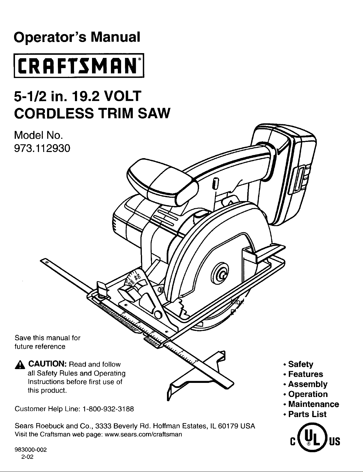
5-1/2 in. 19.2 VOLT
CORDLESS TRIM SAW
Model No.
973.112930
Save this manual for
future reference
_I= CAUTION: Read and follow
all Safety Rules and Operating
Instructions before first use of
this product.
Customer Help Line: 1-800-932-3188
Sears Roebuck and Co., 3333 Beverly Rd. Hoffman Estates, IL 60179 USA
visit the Craftsman web page: www.sears.com/craftsman
983000-002
2-02
• Safety
• Features
• Assembly
• Operation
• Maintenance
• Parts List
0( us
Page 2
• Table Of Contents and Warranty ................................................................................................................................ 2
• Introduction and General Safety Rules .................................................................................................................... 3-4
• Specific Safety Rules and Symbols ......................................................................................................................... 4-7
• Product Specifications, Unpacking, and Accessories ................................................................................................. 8
• Features ................................................................................................................................................................ 8-10
• Assembly .............................................................................................................................................................. 11-12
• Operation ............................................................................................................................................................. 13-20
• Maintenance ............................................................................................................................................................. 21
• Exploded ViewAnd Repair Parts List .................................................................................................................. 22-23
• Parts Ordering/Service ........................................................................................................................................... 24
FULL ONE YEAR WARRANTY ON CRAFTSMAN CORDLESS TRIM SAW
If this CRRFTSMAN Cordless Trim Saw fails to give complete satisfaction within one year from the date of purchase,
RETURN IT TO THE NEAREST SEARS STORE OR SEARS SERVICE CENTER IN THE UNITED STATES, and Sears
will repair it, free of charge.
If this [RRFTTMRN Cordless Trim Saw is used for commercial or rental purposes, this warranty applies for only 90 days
from the date of purchase.
This warranty gives you specific legal rights, and you may also have other rights which vary from state to state.
Sears, Roebuck and Co., Dept. 817WA, Hoffman Estates, IL 60179
_I, Look for this symbol to point out important safety precautions. It means attention!!! Your safety is
involved.
_1= WARNING:
The operation of any power tool can result in foreign objects being thrown into your eyes, which can
result in severe eye damage. Before beginning power tool operation, always wear safety goggles or
safety glasses with side shields and a full face shield when needed. We recommend Wide Vision
Safety Mask for use over eyeglasses or standard safety glasses with side shields, available at Sears
Retail Stores. Always wear eye protection which is marked to comply with ANSI Z87.1.
SAFETY AND INTERNATIONAL SYMBOLS
This operator's manual describes safety and international symbols and pictographs that may appear on this product.
Read the operator's manual for complete safety, assembly, operating and maintenance, and repair information.
MEANING
Do not expose to rain or use in damp locations.
2
Page 3
Yourtrimsawhasmanyfeaturesformakingyourcutting
operationsmorepleasantandenjoyable.Safety,
performanceanddependabilityhavebeengiventop
priorityinthedesignofthistrimsawmakingiteasyto
maintainandoperate.
CAUTION:Carefullyreadthroughthisentire
operator'smanualbeforeusingyournewtrimsaw.
PaycloseattentiontotheGeneralSafetyRules,
SpecificSafetyRules,Symbols,Warnings,and
Cautions.Ifyouuseyourtrimsawproperlyandonly
forit'sintendeduse,youwillenjoyyearsofsafe,
reliableservice.
WARNING: Read and follow all instructions.
H
Failure to follow all instructions listed below, may
result in electric shock, fire and/or serious personal
injury.
SAVE THESE INSTRUCTIONS
Work Area
• Keep your work area clean and well lit. Cluttered
benches and dark areas invite accident.
• Do not operate power tools in explosive atmo-
spheres, such as in the presence of flammable
liquids, gases, or dust. Power tools create sparks
which may ignite the dust or fumes.
• Keep bystanders, children, and visitors away while
operating a power tool. Distractions can cause you
to lose control.
Electrical Safety
• Do not abuse the cord. Never use the cord to carry
the charger. Keep cord away from heat, oil, sharp
edges, or moving parts. Replace damaged cords
immediately. Damaged cords may create a fire.
• A battery operated tool with integral batteries or a
separate battery pack must be recharged only with
the specified charger for the battery. A charger that
may be suitable for one type of battery may create a
risk of fire when used with another battery. Use battery
only with charger listed.
MODEL BATTERY PACK CHARGER
973.112930 Item No. _9-11375 Item No. 9-11041
(1310715) (1425301 )
Use battery operated tool only with specifically
designated battery pack. Use of any other batteries
may create a risk of fire. Use only with battery pack
listed.
Personal Safety
• Stay alert, watch what you are doing and use
common sense when operating a power tool. Do
not use tool while tired or under the influence of
drugs, alcohol, or medication. A moment of inatten-
tion while operating power tools may result inserious
personal injury.
• Dress properly. Do not wear loose clothing or
jewelry. Contain long hair. Keep your hair, clothing,
and gloves away from moving parts. Loose clothes,
jewelry, or long hair can be caught in moving parts.
• Avoid accidental starting. Be sure switch is in the
locked or off position before inserting battery
pack. Carrying tools with your finger on the switch or
inserting the battery pack into a tool with the switch on
invites accidents.
• Remove adjusting keys or wrenches before turn-
ing the tool on. A wrench or a key that is left attached
to a rotating partof the tool may result inpersonal
injury.
• Do not overreach. Keep proper footing and bal-
ance at all times. Proper footing and balance enable
better control of the tool in unexpected situations.
• Use safety equipment. Always wear eye protection.
Dust mask, nonskid safety shoes, hard hat, or hearing
protection must be used for appropriate conditions.
Tool Use and Care
• Use clamps or other practical way to secure and
support the workpiece to a stable platform. Holding
the work by hand or against your body is unstable and
may lead to loss of control.
• Do not force tool. Use the correct tool for your
application. The correct tool will do the job better and
safer at the rate for which it is designed.
Page 4
• Do not use tool if switch does not turn it on or off. •
A tool that cannot be controlled with the switch is
dangerous and must be repaired.
• Disconnect battery pack from tool or place the
switch in the locked or off position before making
any adjustments, changing accessories, or storing •
tool. Such preventive safety measures reduce the risk
of starting the tool accidentally.
• Store idle tools out of the reach of children and
other untrained persons. Tools are dangerous in the Service
hands of untrained users.
• When battery pack is not in use, keep it away from
other metal objects like: paper clips, coins, keys,
nails, screws, or other small metal objects that can •
make a connection from one terminal to another.
Shorting the battery terminals together may cause
sparks, burns, or a fire.
• Maintain tools with care. Keep cutting tools sharp
and clean. Properly maintained tools with sharp
cutting edges are less likely to bind and are easier to
control.
Check for misalignment or binding of moving
parts, breakage of parts, and any other condition
that may affect the tool's operation. If damaged,
have the tool serviced before using. Many accidents
are caused by poorly maintained tools.
Use only accessories that are recommended by
the manufacturer for your model. Accessories that
may be suitable for one tool, may create a risk of injury
when used on another tool.
• Tool service must be performed by qualified repair
personnel. Service or maintenance performed by
unqualified personnel may result ina risk of injury.
When servicing a tool, use only identical replace-
ment parts. Follow instructions in the Maintenance
section of this manual. Use of unauthorized parts or
failure to follow Maintenance Instructions may create a
risk of shock or injury.
Hold tool by insulated gripping surfaces when performing an operation where the cutting tool may contact hidden
wiring. Contact with a "live" wire will make exposed metal parts of the tool "live" and shock the operator.
Additional Rules For Safe Operation
• Know your power tool. Read operator's manual
carefully. Learn its applications and limitations, as
well as the specific potential hazards related to
this tool. Following this rule will reduce the risk of
electric shock, fire, or serious injury.
• Make sure your extension cord is in good condi-
tion. When using an extension cord, be sure to use
one heavy enough to carry the current your prod-
uct will draw. A wire gage size (A.W.G.) of at least
16 is recommended for an extension cord 100 feet
or less in length. A cord exceeding 100 feet is not
recommended. If in doubt, use the next heavier
gage. The smaller the gage number, the heavier
the cord. An undersized cord will cause a drop in line
voltage resulting in loss of power and overheating.
Important Rules For Battery Tools
• Battery tools do not have to be plugged into an
electrical outlet; therefore, they are always in
operating condition. Be aware of possible hazards
when not using your battery tool or when chang-
ing accessories.
• Do not place battery tools or their batteries near
fire or heat. This will reduce the risk of explosion and
possible injury.
_, WARNING: Batteries vent hydrogen gas and can
explode in the presence of a source of ignition, such
as a pilot light. To reduce the risk of serious personal
injury, never use any cordless product in the pres-
ence of open flame. An exploded battery can propel
debris and chemicals. If exposed, flush with water
immediately.
Do not charge battery tool in a damp or wet loca-
tion. Following this rule will reduce the risk of electric
shock, fire, or serious personal injury.
Your battery tool should be charged in a location
where the temperature is more than 50°F but less
than IO0°F. Following this rule will reduce the risk of
electric shock, fire, or serious personal injury.
Under extreme usage or temperature conditions,
battery leakage may occur. If liquid comes in
contact with your skin, wash immediately with
soap and water, then neutralize with lemon juice or
vinegar. If liquid gets into your eyes, flush them
with clean water for at least 10 minutes, then seek
immediate medical attention. Following this rule will
reduce the risk of serious personal injury.
4
Page 5
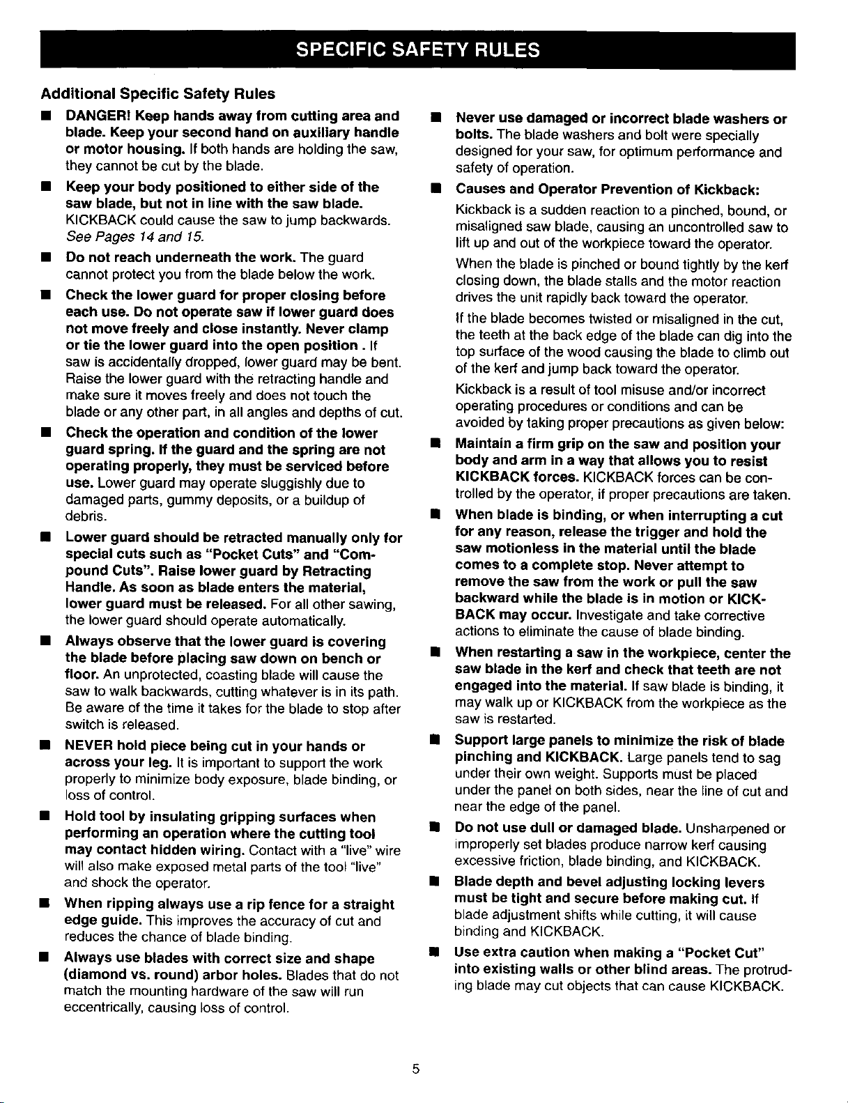
Additional Specific Safety Rules
• DANGER! Keep hands away from cutting area and
blade. Keep your second hand on auxiliary handle
or motor housing. If both hands are holdingthe saw,
they cannot be cut by the blade.
Keep your body positioned to either side of the
saw blade, but not in line with the saw blade.
KICKBACK could cause the saw to jump backwards.
See Pages 14 and 15.
• Do not reach underneath the work. The guard
cannot protect you from the blade below the work.
• Check the lower guard for proper closing before
each use. Do not operate saw if lower guard does
not move freely and close instantly. Never clamp
or tie the lower guard into the open position. If
saw isaccidentally dropped, lower guard may be bent.
Raise the lower guard with the retracting handle and
make sure it moves freely and does not touch the
blade or any other part, in all angles and depths of cut.
• Check the operation and condition of the lower
guard spring. If the guard and the spring are not
operating properly, they must be serviced before
use. Lower guard may operate sluggishly due to
damaged parts, gummy deposits, or a buildup of
debris.
• Lower guard should be retracted manually only for
special cuts such as "Pocket Cuts" and "Com-
pound Cuts". Raise lower guard by Retracting
Handle. As soon as blade enters the material,
lower guard must be released. For all other sawing,
the lower guard should operate automatically.
• Always observe that the lower guard is covering
the blade before placing saw down on bench or
floor. An unprotected, coasting blade will cause the
saw to walk backwards, cutting whatever is in its path.
Be aware of the time it takes for the blade to stop after
switch is released.
NEVER hold piece being cut in your hands or
across your leg. It is important to support the work
properly to minimize body exposure, blade binding, or
loss of control.
• Hold tool by insulating gripping surfaces when
performing an operation where the cutting tool
may contact hidden wiring. Contact with a "live" wire
will also make exposed metal parts of the tool "live"
and shock the operator.
• When ripping always use a rip fence for a straight
edge guide. This improves the accuracy of cut and
reduces the chance of blade binding.
• Always use blades with correct size and shape
(diamond vs. round) arbor holes. Blades that do not
match the mounting hardware of the saw will run
eccentrically, causing loss of control.
Never use damaged or incorrect blade washers or
bolts. The blade washers and bolt were specially
designed for your saw, for optimum performance and
safety of operation.
• Causes and Operator Prevention of Kickback:
Kickback is a sudden reaction to a pinched, bound, or
misalignsd saw blade, causing an uncontrolled saw to
lift up and out of the workpiece toward the operator.
When the blade is pinched or bound tightly by the kerf
closing down, the blade stalls and the motor reaction
drives the unit rapidly back toward the operator.
If the blade becomes twisted or misaligned in the cut,
the teeth at the back edge of the blade can dig into the
top surface of the wood causing the blade to climb out
of the kerr and jump back toward the operator.
Kickback is a result of tool misuse and/or incorrect
operating procedures or conditions and can be
avoided by taking proper precautions as given below:
Maintain a firm grip on the saw and position your
body and arm in a way that allows you to resist
KICKBACK forces. KICKBACK forces can be con-
trolled by the operator, if proper precautions are taken.
When blade is binding, or when interrupting a cut
for any reason, release the trigger and hold the
saw motionless in the material until the blade
comes to a complete stop. Never attempt to
remove the saw from the work or pull the saw
backward while the blade is in motion or KICK-
BACK may occur. Investigate and take corrective
actions to eliminate the cause of blade binding.
When restarting a saw in the workpiece, center the
saw blade in the kerf and check that teeth are not
engaged into the material. If saw blade is binding, it
may walk up or KICKBACK from the workpiece as the
saw is restarted.
Ill Support large panels to minimize the risk of blade
pinching and KICKBACK. Large panels tend to sag
under their own weight. Supports must be placed
under the panel on both sides, near the line of cut and
near the edge of the panel.
• Do not use dull or damaged blade. Unsharpened or
improperly set blades produce narrow kerr causing
excessive friction, blade binding, and KICKBACK.
• Blade depth and bevel adjusting locking levers
must be tight and secure before making cut. If
blade adjustment shifts while cutting, it will cause
binding and KICKBACK.
Use extra caution when making a "Pocket Cut"
into existing walls or other blind areas. The protrud-
ing blade may cut objects that can cause KICKBACK.
5
Page 6
_, WARNING: Never use a battery that has been •
dropped or received a sharp blow. A damaged
battery is subject to explosion. Properly dispose of a
dropped battery immediately. Failure to heed this
warning can result in serious personal injury.
• Save these instructions. This manual contains
important safety and operating instructions for
charger. Following this rule will reduce the risk of
electric shock, fire, or serious personal injury.
• Before using battery charger, read all instructions
and cautionary markings in this manual, on battery
charger, and product using battery charger. Follow-
ing this rule will reduce the risk of electric shock, fire,
or serious personal injury.
_LCAUTION: To reduce risk of injury, charge only
nickel-cadmium and nickel metal hydride type
rechargeable batteries. Other types of batteries
may burst causing personal injury and damage.
Following this rule will reduce the risk of electric
shock, fire, or serious personal injury.
• Do not expose charger to rain or snow. Following
this rule will reduce the risk of electric shock, fire, or
serious personal injury.
• Use of an attachment not recommended or sold by
the battery charger manufacturer may result in a
risk of fire, electric shock, or injury to persons.
Following this rule will reduce the risk of electric shock,
fire, or serious personal injury.
• To reduce the risk of damage to charger body and
cord, pull by charger plug rather than cord when •
disconnecting charger. Following this rule will reduce
the risk of serious personal injury.
• Make sure cord is located to that it will not be
stepped on, tripped over, or otherwise subjected to
damage or stress. Following this rule will reduce the
risk of serious personal injury.
• An extension cord should not be used unless
absolutely necessary. Use of improper extension
cord could result in a riskof fire and etectric shock. If
extension cord must be used, make sure:
a. That pins on plug of extension cord are the same
number, size and shape as those of plug on
charger.
b. That extension cord is properly wired and in good
electrical condition; and
c. That wire size is large enough forAC ampere rating
of charger as specified below:
Cord Length (Feet) 25" 50" 100"
Cord Size (AWG) 16 16 16
Note: AWG = American Wire Gage
Do not operate charger with a damaged cord or
plug. If damaged, have replaced immediately by a
qualified serviceman. Following this rule will reduce the
riskof electric shock, fire, or serious personal injury.
• Do not operate charger if it has received a sharp
blow, been dropped, or otherwise damaged in any
way; take it to a qualified serviceman. Following this
rule will reduce the risk of electric shock, fire, or
serious personal injury.
• Do not disassemble charger; take it to a qualified
serviceman when service or repair is required.
Incorrect reassembly may result in a risk of elec-
tric shock or fire. Following this rule will reduce the
risk of electric shock, fire, or serious personal injury.
• To reduce the risk of electric shock, unplug
charger from outlet before attempting any mainte-
nance or cleaning. Turning off controls will not
reduce this risk. Following this rule will reduce the
risk of electric shock, fire, or serious personal injury.
• Do not use charger outdoors. Following this rule will
reduce the risk of electric shock, fire, or serious
personal injury.
• Disconnect charger from power supply when not
in use. Following this rule will reduce the risk of
electric shock, fire, or serious personal injury.
,_ DANGER: RISK OF ELECTRIC SHOCK. DO NOT
TOUCH UNINSULATED PORTION OF OUTPUT
CONNECTOR OR UNINSULATED BATTERY
TERMINAL.
Save these instructions. Refer to them frequently
and use them to instruct others who may use this
tool. If you loan someone this tool, loan them
these instructions also. Following this rule will
reduce the risk of electric shock, fire, or serious
personal injury.
_LWARNING: Some dust created by power sanding,
sawing, grinding, drilling, and other construction
activities contains chemicals known to cause
cancer, birth defects or other reproductive harm.
Some examples of these chemicals are:
• lead from lead-based paints,
• crystalline silica from bricks and cement
and other masonry products, and
• arsenic and chromium from chemically-
treated lumber.
Your risk from these exposures varies, depending
on how often you do this type of work. To reduce
your exposure to these chemicals: work in a well
ventilated area, and work with approved safety
equipment, such as those dust masks that are
specially designed to filter out microscopic particles.
SAVETHESEINSTRUCTIONS
6
Page 7
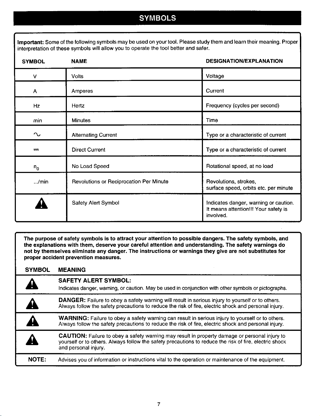
Important: Some ofthe following symbols may be used on your tool. Please study them and learn their meaning. Proper
interpretation of these symbols will allow you to operate the tool better and safer.
SYMBOL NAME DESIGNATION/EXPLANATION
V Volts Voltage
A Amperes Current
Hz Hertz Frequency (cycles per second)
min Minutes Time
Alternating Current Type or a characteristic of current
Direct Current Type or a characteristic of current
no No Load Speed Rotational speed, at no load
.../min Revolutions or Reciprocation Per Minute Revolutions, strokes,
surface speed, orbits etc. per minute
,_ Safety Alert Symbol Indicates danger, warning or caution.
The purpose of safety symbols is to attract your attention to possible dangers. The safety symbols, and
the explanations with them, deserve your careful attention and understanding. The safety warnings do
not by themselves eliminate any danger. The instructions or warnings they give are not substitutes for
proper accident prevention measures.
SYMBOL MEANING
SAFETY ALERT SYMBOL:
A
A
A
A
Indicates danger, warning, or caution. May be used in conjunction with other symbols or pictographs.
DANGER: Failure to obey a safety warning will result in serious injury to yourself or to others.
Always follow the safety precautions to reduce the risk of fire, electric shock and personal injury.
WARNING: Failure to obey a safety warning can result in serious injury to yourself or to others.
Always follow the safety precautions to reduce the risk of fire, electric shock and personal injury.
CAUTION: Failure to obey a safety warning may result in property damage or personal injury to
yourself or to others. Always follow the safety precautions to reduce the risk of fire, electric shock
and personal injury.
It means attention!!! Your safety is
involved.
NOTE: Advises you of information or instructions vital to the operation or maintenance of the equipment.
7
Page 8
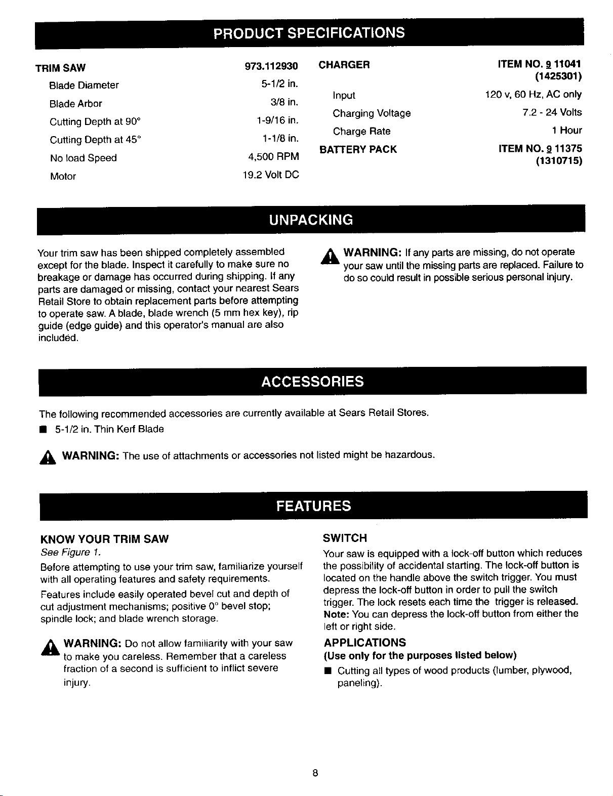
TRIM SAW 973.112930
Blade Diameter 5-1/2 in.
Blade Arbor 318 in.
Cutting Depth at 90° 1-9/16 in.
Cutting Depth at 45° 1-1/8 in.
No load Speed 4,500 RPM
Motor 19.2 Volt DC
CHARGER
Input
Charging Voltage
Charge Rate
BATrERY PACK
ITEM NO. 9 11041
(1425301)
120 v,60 Hz, AC only
7.2 - 24 Volts
t Hour
ITEM NO. 9_11375
(1310715)
Your trim saw has been shipped completely assembled
except for the blade. Inspect it carefully to make sure no
breakage or damage has occurred during shipping. If any
parts are damaged or missing, contact your nearest Sears
Retail Store to obtain replacement parts before attempting
to operate saw. A blade, blade wrench (5 mm hex key), rip
guide (edge guide) and this operator's manual are also
included.
The following recommended accessories are currently available at Sears Retail Stores.
• 5-1/2 in. Thin Kerf Blade
_lb WARNING: The use of attachments or accessories not listed might be hazardous.
KNOW YOUR TRIM SAW
See Figure 1.
Before attempting to use your trim saw, familiarize yourself
with all operating features and safety requirements.
Features include easily operated bevel cut and depth of
cut adjustment mechanisms; positive 0° bevel stop;
spindle lock; and blade wrench storage.
,_ WARNING: Do not allow familiarity with your saw
to make you careless. Remember that a careless
fraction of a second is sufficient to inflict severe
injury.
,_ WARNING: If any parts are missing, do not operate
your saw until the missing parts are replaced. Failure to
do so could result in possible serious personal injury.
SWITCH
Your saw is equipped with a lock-off button which reduces
the possibility of accidental starting. The lock-off button is
located on the handle above the switch trigger. You must
depress the lock-off button in order to pull the switch
trigger. The lock resets each time the trigger is released.
Note: You can depress the lock-off button from either the
left or right side.
APPLICATIONS
(Use only for the purposes listed below)
• Cutting all types of wood products (lumber, plywood,
paneling).
Page 9

SPINDLE
LOCKBUTTON
LOCK-OFF
BUTTON
BATrERY
PACK
SWITCH
TRIGGER
RIP
GUIDESCREW
(WINGSCREW)
BEVELCUTADJUSTMENT
(BEVELADJUSTMENTKNOB)
BASE
ASSEMBLY
RIPGUIDE
UPPER
BLADEGUARD
LOWERBLADE
GUARDHANDLE
LOWER
BLADEGUARD
BLADE
BLADEW_
STORAG_
DEPTHOF
BLADEWRENCH CUTADJUSTMENT
(5 mmHEXKEY) (DEPTHADJUSTMENTKNOB) Fig. 1
Page 10

LED FUNCTION OF CHARGER
YELLOWANDGREENLEDSONINDICATESDEEPLY
DISCHARGEDOR DEFECTIVEBATTERYPACK.
CHARGER REDLEDONINDICATES
FASTCHARGINGMODE
GREENLEDONAFTERFASTCHARGING
CYCLE,INDICATESFULLYCHARGEDBATTERY
PACKANDINTRICKLECHARGEMODE.
MOUNTING CHARGER
See Figure3.
Your charger has a "key hole" hanging feature for conve-
nient, space saving storage. Therefore, if desired, you can
mount your charger to a wall. Screws should be installed
so that center distances are 4-1/2 inches apart.
4-I/2 in.
Fig, 2
BACKSIDEOFCHARGER
Fig. 3
10
Page 11

_L WARNING: Always remove battery pack from your
saw when you are assembling parts, making
adjustments, assembling or removing blades,
cleaning, or when not in use. Removing battery pack
will prevent accidental starting that could cause
serious personal injury.
Note: Your saw is assembled with the battery pack
attached.
TO REMOVE BATTERY PACK
See Figure 4.
• Locate latches on side of battery pack and depress to
release battery pack from your saw. See Figure 4.
• Remove battery pack from your saw.
DEPRESSLATCHESTO
TO
REMOVE
TO
INSTALL LATCHES
RELEASEBATTERYPACK
SPINDLE
LOCKBUTTON
LOWERBLADE
GUARDHANDLE
BLADE
LADEWASHER OUTER
BLADEWASHER
BLADESCREW Fig. 5
• Remove blade wrench (5 mm hex key) from storage
area. See Figure 1.
• Depress spindle lock button and remove blade screw
and outer blade washer. See Figure 5.
Note: Turn blade screw clockwise to remove.
• Wipe a drop of oil onto inner blade washer and outer
blade washer where they contact blade.
BAI'I'ERYPACK
TO ASSEMBLE OR REMOVE BLADE
TO ASSEMBLE BLADE:
See Figure 5.
WARNING: A 5-1/2 in. blade is the maximum blade
capacity of your saw. Never use a blade that is too
thick to allow outer blade washer to engage with the
flats on the spindle. Larger blades will come in
contact with the blade guard, while thicker blades will
prevent blade screw from securing blade on spindle.
Either of these situations could result in a serious
accident.
• Remove battery pack from saw.
_ll WARNING: Failure to remove battery pack from
saw could result in accidental starting causing
possible serious personal injury.
• Locate latches on side of battery pack and depress to
release battery pack from your saw. See Figure 4.
Fig. 4
WARNING: If inner blade washer has been re-
u
moved, replace it before placing blade on spindle.
Failure to do so could cause an accident since blade
will not tighten properly.
• Fit saw blade inside lower blade guard and onto
spindle.
Note: The saw teeth point upward at the front of saw
as shown in figure 5.
• Replace outer blade washer.
• Depress spindle lock button, then replace blade screw.
Tighten blade screw securely.
Note: Turn blade screw counterclockwise to tighten.
• Return blade wrench to storage area.
REMEMBER: Never use a blade that is too thick to
allow the outer blade washer to engage with the flats
on the spindle.
11
Page 12

TO REMOVE BLADE
See Figure 6.
• Remove battery pack from saw.
WARNING: Failure to remove battery pack from
saw could result in accidental starting causing
possible serious personal injury.
• Remove blade wrench from storage area. See Figure 1.
• Position saw as shown in figure 6, depress spindle lock
button, and remove blade screw.
Note: Turn blade screw clockwise to remove.
• Remove outer blade washer. See Figure 5.
Note: Blade can be removed at this point.
DEPRESSSPINDLE
LOCKBuTroN
TO INSTALL BA'n'ERY PACK
See Figure 7,
Note: Battery pack is shipped in a low charge condition.
Therefore, it must be charged prior to use. Refer to page
13, "CHARGING BATTERY PACK" for charging
instructions.
• Place battery pack in your saw. Align raised rib on
battery pack with groove inside saw, then slide battery
pack in saw as shown in figure 7.
• Make sure the latches on each side of your battery
pack snap into place and battery pack is secured in
saw before beginning operation.
TO
LOOSEI
\
\
TO
TIGHTEN
BLADE
WRENCH
SCREW
Fig. 6
_l, CAUTION: When placing battery pack in your saw,
be sure raised rib on battery pack aligns with groove
inside saw and latches snap into place properly.
Improper assembly can cause damage to saw and
battery pack.
BATTERYPACK
LATCHES
Fig. 7
12
Page 13

,_ WARNING: Always wear safety goggles or safety
glasses with side shields when operating tools.
Failure to do so could result in objects being thrown
into your eyes, resulting in possible serious injury.
CHARGING BATTERY PACK
The battery pack for this tool has been shipped in a low
charge condition to prevent possible problems. Therefore,
you should charge it until light on front of charger changes
from red to green.
Note: Batteries will not reach full charge the first time they
are charged. Allow several cycles (cutting followed by
recharging) for them to become fully charged.
TO CHARGE
• Charge battery pack only with the charger provided.
• Make sure power supply is normal house voltage,
120 volts, 60 Hz, AC only.
• Connect charger to power supply.
• Place battery pack in charger aligning raised rib on
battery pack with groove in charger. See Figure 8.
BATTERYPACK
SHOWNINCHARGER
CHARGER
• Press down on battery pack to be sure contacts on
battery pack engage properly with contacts in charger.
• Normally, the red LED on charger will come on. This
indicates charger is in fast charging mode.
• Red LED should remain on for approximately 1 hour
then the green LED will come on. Green LED on
indicates battery pack is fully charged and charger is in
trickle charge mode. Note: Green LED will remain on
until battery pack is removed from charger or charger is
disconnected from power supply.
• If both yellow and green LED come on, this indicates a
deeply discharged or defective battery pack.
Allow battery pack to remain in charger for 15 to 30
minutes. When battery pack reaches normal voltage
range, red LED should come on.
If red LED does not come on after 30 minutes, this
indicates a defective battery pack and should be
replaced.
• After normal usage, 1 hour of charging time is required
to be fully charged.
• The battery pack will become slightly warm to the
touch while charging. This is normal and does not
indicate a problem.
• Do not place charger in an area of extreme heat or
cold. It will work best at normal room temperature.
Note: Charger and battery pack should be placed in a
location where the temperature is more than 5O°F but
less than 100°F.
• When the batteries become fully charged, unplug your
charger from power supply and remove the battery
pack.
REDLEDON INDICATES
LED FUNCTIONS OF CHARGER
LED WILL BE ON TO INDICATE STATUS OF CHARGER
AND BATTERY PACK:
• Red LED on = Fast Charging Mode.
• Green LED on = Fully Charged and in trickle charge
mode.
MODE
GREENLEDON AFTERFASTCHARGING
CYCLE,INDICATESFULLYCHARGEDBATTERY
PACKANDINTRICKLECHARGEMODE.
YELLOWANDGREENLEDSONINDICATESDEEPLY
DISCHARGEDOR DEFECTIVEBATI'ERYPACK.
Fig. 8
• Green LED on = When battery pack is inserted into
charger, indicates hot battery pack or that battery pack
is out of or below normal temperature range.
• Yellow and Green LEDs on = Deeply discharged or
defective battery pack.
• No LED on = Defective charger or battery pack.
13
Page 14

_I1 CAUTION: To prevent damage to battery pack,
remove battery pack from charger immediately if no
LED comes on. Return battery pack and charger to
your nearest Sears Service Center for checking or
replacing. Also, if you are removing battery pack
from charger and no LEDs are on, return both battery
pack and charger to your nearest Sears Service
Center. Do not insert another battery pack into
charger. A damaged charger may damage a battery
pack.
IMPORTANT INFORMATION FOR RECHARGING
HOT BATTERY PACK
When using your saw continuously, the batteries in your
battery pack will become hot. You should let a hot battery
pack cool down for approximately 30 minutes before
attempting to recharge. When the battery pack becomes
discharged and is hot, this will cause the green LED to
come on instead of the red LED. After 30 minutes, reinsert
battery pack in charger. If green LED continues to remain
on, return battery pack to your nearest Sears Repair
Center for checking or replacing. Once the battery pack
cools down, it will recharge battery pack in fast charging
mode as normal.
Note: This situation only occurs when extreme continuous
use of your saw causes the batteries to become hot. It
does not occur under normal circumstances. Refer to
"CHARGING BA'rI'ERY PACK" for normal recharging of
batteries. If the charger does not charge your battery pack
under normal circumstances, return both the battery pack
and charger to your nearest Sears repair center for
electrical check.
IMPORTANT INFORMATION FOR RECHARGING
COOL BATTERY PACK
If battery pack is below normal temperature range, the
green LED on charger will come on. Allow battery pack to
reach normal temperature, then the red LED will come on.
Note: Refer to "CHARGING BATTERY PACK" for
normal recharging of batteries. If the charger does not
charge your battery pack under normal circumstances,
return both the battery pack and charger to your nearest
Sears Repair Center for electrical check.
SAW BLADES
The best of saw blades will not cut efficiently if they are not
kept clean, sharp, and properly set. Using a dull blade will
place a heavy load on your saw and increase the danger
of kickback. Keep extra blades on hand, so that sharp
blades are always available.
Gum and wood pitch hardened on blades will slow your
saw down. Use gum and pitch remover, hot water, or
kerosene to remove these accumulations. Do not use
gasoline.
BLADE GUARD SYSTEM
The lower blade guard attached to your trim saw is
there for your protection and safety. It should never be
altered for any reason. If it becomes damaged or
begins to return slow or sluggish, do not operate your
saw until the damage has been repaired or replaced.
Always leave guard in operating position when using
saw.
_i, DANGER: When sawing through workpiece, lower
blade guard does not cover blade on the underside of
workpiece. Since blade is exposed on underside of
workpiece, keep hands and fingers away from cutting
area. Any part of your body coming in contact with
moving blade will result in serious injury.
See Figure 9.
LOWERBLADEGUARD
ISINUP POSITION
WHENMAKINGA CUT
BLADEEXPOSEDON
UNDERSIDEOF WORKPIECE
Never use saw when guard is not operating correctly.
Guard should be checked for correct operation before
each use. If you drop your saw, check the lower blade
guard and bumper for damage at all depth settings
before reuse, Note: The guard is operating correctly
when it moves freely and readily returns to the closed
position. If for any reason your lower blade guard
does not close freely, take it to the nearest Sears Parts
and Repair Center for service before using.
Fig. 9
14
Page 15

KICKBACK
See Figure 10.
TO LESSEN THE CHANCE OF KICKBACK:
• Always keep the correct blade depth setting - the
correct blade depth setting for all cuts should not
exceed 1/4 in. below the material to be cut.
See Figure 12. One blade tooth below the material to
be cut works best for most efficient cuttingaction.
BLADESETTOO DEEP
The best guard against kickback is to avoid dangerous
practices.
Kickback occurs when the blade stalls rapidly and the saw
is driven back towards you. Blade stalling is caused by any
action which pinches the blade inthe wood.
_i, DANGER: Release switch immediately if blade
binds or saw stalls. Kickback could cause you to lose
control of your saw. Loss of control can lead to
serious injury.
KICKBACK IS CAUSED BY:
• Incorrect blade depth setting. See Figure 10.
• Sawing into knots or nails inworkpiece.
• Twisting blade while making a cut.
• Making a cut with a dull, gummed up, or improperly set
blade.
• Incorrectly supporting workpiece. See Figure 11.
Fig. 10
CORRECTBLADEDEPTHSETTING=
BLADEEXPOSEDONEBLADETOOTH
BELOWTHEMATERIALTO BECUT
• Inspect the workpiece for knots or nails before
beginning a cut. Never saw into a knot or nail.
• Make straight cuts. Always use a straight edge guide
when rip cutting. This helps prevent twisting the blade
in the cut.
• Always use clean, sharp and properly set btades.
Never make cuts with dull blades.
• To avoid pinching the blade, support the workpiece
properly before beginning a cut. The right and wrong
ways to support large pieces of work are shown in
figures 11 and 13.
Fig. 12
• Forcing a cut.
• Cutting warped or wet lumber.
• Tool misuse or incorrect operating procedures.
Fig. 11
RIGHT Fig. 13
15
Page 16

• Whenmakingacutusesteady,evenpressure.
Neverforcecuts.
• Donotcutwarpedorwetlumber.
• Alwaysholdyoursawfirmlywithbothhandsandkeep
yourbodyina balancedpositionsoastoresistthe
forcesofkickbackshoulditoccur.
When using your saw, always stay alert and exercise
control. Do not remove your saw from workpiece
while the blade is moving.
DEPTH OF CUT ADJUSTMENT
Always keep correct blade depth setting. The correct
blade depth setting for all cuts should not exceed 1/4 inch
below the material to be cut. More blade depth will
increase the chance of kickback and cause the cut to be
rough. One blade tooth below the material to be cut works
best for most efficient cutting action.
TO ADJUST BLADE DEPTH
• Remove battery pack from saw.
STARTING A CUT
Know the right way to use your saw.
See Figure 15.
WARNING: Failure to remove battery pack from
saw could result in accidental starting causing
possible serious personal injury.
• Loosen depth adjustment knob. See Figure 14,
TO RAISE
SAW
,TO
TIGHTEN
TO
LOOSEN DEPTH
TO ADJUSTMENT
LOWERSAW KNOB
BASE
ASSEMBLY
Fig, 15
Never use your saw as shown in figure 16.
Fig. 14
• Hold base flat against the workpiece and raise or lower
saw until the required depth is reached.
• Tighten depth adjustment knob securely.
WRONG Fig. 16
Never place your hand on the workpiece behind your
saw while making a cut.
,_ WARNING: To make sawing easier and safer,
always maintain proper control of your saw. Loss of
control of your saw could cause an accident resulting
in possible serious injury.
16
Page 17

TO HELP MAINTAIN CONTROL:
• Always support your workpiece near the cut.
• Support your workpiece so the cut will be on your left.
• Clamp your workpiece so it will not move during the cut.
Ptace your workpiece with its good side down.
Note: The good side is the side on which appearance is
important.
Before beginning a cut, draw a guideline along the desired
line of cut. Then place front edge of base on that part of
your workpiece that is solidily supported. See Figure 15.
Never place your saw on that part of the workpiece
that will fall off when the cut is made. See Figure 17.
Hold your saw firmly with both hands.
See Figure 18
RIGHT Fig. 18
Depress the lock-off button and squeeze the switch trigger
to start your saw. Always let the blade reach full speed,
then guide your saw into the workpiece.
WRONG Fig. 17
_, WARNING: The blade coming in contact with the
workpiece before it reaches full speed could cause
your saw to "kickback" towards you resulting in
serious injury.
When making a cut use steady, eveR. pressure. Forcing
causes rough cuts, could shorten the life of your saw and
could cause "kickback."
REMEMBER:
When sawing through work, the lower blade guard
does not cover the blade, exposing it on the
underside of work. Keep your hands and fingers away
from cutting area. Any part of your body coming in
contact with the moving blade will result in serious
injury.
After you complete your cut release the trigger and allow
the blade to come to a complete stop. Do not remove
your saw from workpiece while the blade is moving.
_, CAUTION: When lifting your saw from the
workpiece, the blade is exposed on the underside of
your saw until the lower blade guard Closes. Make
sure lower blade guard is closed before setting your
saw down on work surface.
17
Page 18

TOCROSSCUTORRIPCUT
When making a cross cut or rip cut, align your line of cut
with the outer blade guide notch on the saw base as
shown in figure 19.
TOPVIEWOF SAW
BLADE
GUIDENOTCH
ALIGNOUTERBLADEGUIDENOTCHONSAWBASEWITHLINE
OFCUTAS SHOWNWHENMAKINGCROSSCUTSORRIPCUTS
GUIDELINE
OFSAW
Fig. 19
A width of cut scale has been provided on the base of
your saw. When making straight cross cuts or rip cuts, the
scale can be used to measure up to four inches to the
right side of the blade. It can be used to measure up to
one inch to the left side of the blade.
RIP GUIDE (EDGE GUIDE)
Use the rip guide provided with your saw when making
wide ripcuts. Afive inch scale has been provided on the
rip guide. When using the width of cut scale on the base
in combination with the rip guide, cuts can be made up to
6 in. to the left of the rip guide or 8-7/8 in. to the right of
the rip guide.
The rip guide helps prevent the blade from twisting ina
cut. The blade twisting in a cut can cause kickback.
TO ASSEMBLE RIP GUIDE
• Remove battery pack from saw.
,_, WARNING: Failure to remove battery pack from
saw could result in accidental starting causing
possible serious personal injury.
Since blade thicknesses vary, always make a trial cut in
scrap material along a guideline to determine how much,
if any, the guideline must be offset to produce an accurate
cut.
Note: The distance from the line of cut to the guideline is
the amount you should offset the guideline.
WIDTH OF CUT SCALE
See Figure 20.
ASSEMBLY
BASE_
WIDTH0
CUTSCALE
BLADE
Fig. 20
RIP
GUIDESCREW
(WINGSCREW)
RIPGUIDE
(EDGEGUIDE)
PLACERIP
GUIDETHRUHOLES
Fig. 21
• Place rip guide through holes in saw base as shown in
figure 21.
• Adjust rip guide to the width needed.
• Tighten rip guide screw (wing screw) securely.
When using a rip guide, position the face of the rip guide
firmly against the edge of workpiece. This makes for a
true cut without pinching the blade. The guiding edge of
workpiece must be straight for your cut to be straight. Use
caution to prevent the blade from binding in the cut.
18
Page 19

ALTERNATIVE RIP METHOD
See Figure 22.
Using C-clamps, firmly clamp a straight edge to the
workpeice and guide the saw along the straight edge to
achieve a straight rip cut. Do not bind the blade in the cut.
ALTERNATIVEMETHODFORRIPCUTTING
WORKPIECE
STRAIGHT
EDGE
NOTE:C-CLAMP
BOTHENDSOF STRAIGHT
EDGEBEFOREMAKINGCUT
Fig. 22
TO BEVEL CUT
The angle of cut of your saw may be adjusted to any
desired setting between zero and 50°. Note: When
making cuts at 50 °, blade should be set at full depth of
cut.
When making 45° bevel cuts, there is a notch in the saw
base to help you line up the blade with the line of cut.
See Figure 23.
Align your line of cut with the inner blade guide notch on
the saw base when making 45° bevel cuts.
Since blade thicknesses vary and different angles
require different settings, always make a trial cut in
scrap material along a guideline to determine how
much you should offset the guideline on the board to
be cut.
When making a bevel cut hold your saw firmly with both
hands as shown in figure 24.
\
LOWER
BLADEGUARD Fig. 24
Rest the front edge of the base on the workpiece. Depress
the lock-off button and squeeze the switch trigger to start
your saw. Always let the blade reach full speed, then
guide your saw into the workpiece.
_1, WARNING: The blade coming.in contact with the
workpiece before it reaches full speed could cause
saw to "kickback" toward you resulting in serious
injury.
ADJUSTMENTKNOB / _ II
BEVEL ,f--F--'-ll
NVt;UIDEL,NE
ALIGNINNERBLADEGUIDENOTCHONSAWBASEWITH
LINE OFCUTASSHOWNWHENMAKING45° BEVELCUTS
Fig. 23
After you complete your cut release the trigger and allow
the blade to come to a complete stop. After the blade has
stopped, lift your saw from the workpiece.
TO ADJUST BEVEL SETTING
• Remove battery pack from saw.
_1, WARNING: Failure to remove battery pack from
saw could result in accidental starting causing
possible serious personal injury.
• Loosen bevel adjustment knob. See Figure 23.
• Raise motor housing end of saw until you reach desired
angle setting on bevel scale. See Figure 23.
• Tighten bevel adjustment knob securely.
_IL WARNING: Attempting bevel cut without knob
securely tightened can result in serious injury.
19
Page 20

POSITIVE 0° BEVEL STOP • Turn screw and adjust base until square with saw
See Figure 25. blade.
ADJUSTMENT
SCREW
POSITIVE0°
BEVELSTOP
CARPENTER'S
SQUARE
BEVEL
ADJUSTMENT
KNOB
BLADE
•"l]ghten hex nut and bevel adjustment knobsecurely.
_, WARNING: Attempting to make cuts without bevel
adjustment knob securely tightened can result in
serious injury.
TO POCKET CUT
See Figure 26.
WARNING: Always adjust bevel setting to zero
A
before making a pocket cut. Attempting a pocket cut at
any other setting can result in loss of control of your
saw possibly causing serious injury.
Adjust the bevel setting to zero, set blade to correct blade
depth setting, and swing the lower blade guard up using
the lower blade guard handle.
Always raise the lower blade guard with the handle to
avoid serious injury.
While holding lower blade guard by the handle, firmly rest
the front of the base flat against the workpiece with the
rear of the handle raised so the blade does not touch the
workpiece. See Figure 26.
Fig. 25
Your saw has a positive 0° bevel stop, that has been
factory adjusted to assure 0° angle of your saw blade
when making 90° cuts. However, misalignment can occur
during shipping.
TO CHECK
• Remove battery pack from saw.
_1= WARNING: Failure to remove battery pack from
saw could result in accidental starting causing
possible serious personal injury.
• Place your saw in an upside down position on
workbench. See Figure 25.
• Using a carpenter's square, check squareness of saw
blade to the base of your saw.
TO ADJUST
• Remove battery pack from saw.
_1, WARNING: Failure to remove battery pack from
saw could result in accidental starting causing
possible serious personal injury.
LOWERBLADE
GUARDHANDLE
POCKETCUT LOWERBLADEGUARD
Fig. 26
Depress the lock-off button and squeeze the switch trigger
to start your saw. Always let the blade reach full speed
then slowly lower blade into the workpiece until base
is flat against workpiece.
After you complete your cut release the trigger and allow the
blade to come to a complete stop. After the blade has
stopped, remove it from the workpiece. Corners may then be
cleared out with a hand saw or sabre saw.
• Loosen bevel adjustment knob.
• Loosen hex nut securing adjustment screw.
_k WARNING: Never tie the lower blade guard in a
raised position. Leaving the blade exposed could
lead to serious injury.
20
Page 21

_1, WARNING: When servicing, use only identical
Craftsman replacement parts. Use of any other part
may create a hazard or cause product damage.
Avoid using solvents when cleaning plastic parts. Most
plastics are susceptible to damage from various types of
commercial solvents and may be damaged by their use.
Use clean cloths to remove dirt, dust, oil, grease, etc.
_IL WARNING: Do not at any time let brake fluids,
gasoline, petroleum-based products, penetrating oils,
etc. come in contact with plastic parts. They contain
chemicals that can damage, weaken or destroy
plastic.
BATI'ERIES
Your saw's battery pack is equipped with 16 nickel-
cadmium rechargeable batteries. Length of service from
each charging will depend on the type of work you are
doing.
The batteries in this tool have been designed to provide
maximum trouble free life. However, like all batteries, they
will eventually wear out. Do not disassemble battery pack
and attempt to replace the batteries. Handling of these
batteries, especially when wearing rings and jewelry,
could result in a serious burn.
To obtain the longest possible battery life, we suggest the
following:
Do not abuse power tools. Abusive practices can damage
tool as well as workpiece.
Only the parts shown on parts list, page 23, are intended
to be repaired or replaced by the customer. All other parts
should be replaced at a Sears Service Center.
_i, WARNING: Do not attempt to modify this tool or
create accessories not recommended for use with
this tool. Any such alteration or modification is
misuse and could result in a hazardous condition
leading to possible serious personal injury.
• Store and charge your batteries in a cool area.
Temperatures above or below normal room
temperature will shorten battery life.
• Never store batteries in a discharged condition.
Recharge them immediately after they are discharged.
• All batteries gradually lose their charge. The higher the
temperature the quicker they lose their charge. If you
store your tool for long periods of time without using it,
recharge the batteries every month or two. This
practice will prolong battery life.
To preserve natural resou;'ces, please
recycle or dispose of batteries properly.
This product contains nickel-cadmium
battery. Local, state, or federal laws may
prohibit disposal of nickel-cadmium
batteries in ordinary trash.
Consult your local waste authority for information
regarding available recycling and/or disposal options.
BATTERY PACK REMOVAL AND PREPARATION
FOR RECYCLING
WARNING: Upon removal, cover the battery pack's
A
terminals with heavy duty adhesive tape. Do not
attempt to destroy or disassemble battery pack or
remove any of its components. Nickel-cadmium
batteries must be recycled or disposed of properly.
Also, never touch both terminals with metal objects
and/or body parts as short circuit may result. Keep
away from children. Failure to comply with these
warnings could result in fire and/or serious injury.
21
Page 22

CRAFTSMAN 19.2 VOLT CORDLESS TRIM SAW - MODEL NUMBER 973.112930
11
i;
27
26
12
14
28
_'_ ,18
10
19 20
23
16 21 22
24
5
b2
22
25
Page 23

CRAFTSMAN 19.2 VOLT CORDLESS TRIM SAW - MODEL NUMBER 973.112930
The model number will be found on a plate attached to the motor housing. Always mention the model number in all correspondence regarding your
CORDLESS TRIM SAW or when ordering repair parts,
[
SEE BACK PAGE FOR PARTS ORDERING INSTRUCTIONS
PARTS LIST
I
Key
No.
1
2
3
4
5
6
7
8
9
10
11
12
13
14
15
Part
Number Description Quan.
975546-000
3025515
6797401
5224502
975552-000
975551-000
975549-000
975559-000
975558-000
975550-000
9427109
975557-000
6440413
975543-00O
5217802
Carriage Bolt (M6 x 102 mm) ..................... 1
Base Assembly .......................................... 1
Lock Nut ..................................................... 2
Knob ........................................................... 2
Spring ......................................................... 1
Wing Screw ................................................ 1
Base Screw ................................................ 1
Hex Nut ...................................................... 1
Screw ......................................................... 1
Carriage Bolt (M6 x 13 mm) ....................... 1
Data Plate .................................................. 1
Warning Label ............................................ 1
Upper Blade Guard .................................... 1
Upper Blade Guard Screw ......................... 3
Bumper ....................................................... 1
Key PaN
No. Number Description
16 6619302
17 6867201
18 5599402
19 975538-000
20 6850303
21 6600506
22 6112004
23
24 975533-000
25 975532-000
26 *Item No. 9-11375
27 *Item No. 9-11041
28 6795711
29 975553-000
30 3063626
983000-002
Bumper Screw ............................................ 1
Torsion Spring ............................................ 1
Lower Blade Guard .................................... 1
Ball Bearing (NTN #6200LB) ..................... 1
Bearing Retainer ........................................ 1
Bearing Retainer Screw ............................. 4
Inner Blade Washer ................................... 1
Saw Blade .................................................. 1
Outer Blade Washer .................................. 1
Blade Screw ............................................... 1
Battery Pack (1310715) ............................. 1
Charger (1425301) ..................................... 1
Rip Guide ................................................... 1
Blade Wrench (5 mm Hex Key) ................. 1
Combo Kit Carrying Case - Not Shown ..... 1
Operator's Manual
Quan.
* Available At Your Nearest Sears Catalog Order Or Retail Store
** Can Be Purchased Thru RSOS (Retail Special Order System)
23
Page 24

Get it fixed, at your home or ours!
For repair of major brand appliances in your own home...
no matter who made _t,no matter who sold it!
1-800-4-MY-HOME sMAnytime, day or night
(1-800-469-4663)
www.sears.com
To bring in products such as vacuums, lawn equipment and electronics
for repair, call for the location of your nearest Sears Parts & Repair Center.
1-800-488-1222 Anyt,me, day or night
www.sears.com
For the replacement parts, accessories and owner's manuals
that you need to do-it-yourself, call Sears PartsDirect sM!
1-800-366-PART 6 a.m. - 11 p.m. CST,
(1-800-366-7278) 7 days a week
www.sears.com/partsdirect
To purchase or inquire about a Sears Service Agreement:
1-800-827-6655
7 a.m. - 5 p.m. CST, Men - Sat.
Para pedlr serviclo de reparacion a domlclho,
y para ordenar plezas con entrega a domlclho
1-888-SU-HOGAR s.
(1-888-784-6427)
HomeCentral'°
SEARS 1
Au Canada pour service en fran(;ais:
1-877-LE-FOYERS"
(1-877-533-6937)
® Reg=stered Trademark / T. Trademark of Sears Roebuck and Co
© Sears Roebuck and Co ® Marca Reglstrada ! r,_ Marca de Fabnca de Sears Roebuck and Co
 Loading...