

Craftsman 944.629663, 944.629672, 944.629664, 944.629673 Owner's Manual
OWNER’S
MANUAL
MODEL NO.
944.629663
Important:
Read and fol low
all Safety Rules
and In struc tions
Be fore Op er at ing
This Equip ment
Sears Canada, Inc., Toronto, Ontario M5B 2B8
900 SERIES
14 INCH TINE WIDTH
REAR TINE TILLER WITH
COUNTER ROTATING TINES
• Assembly
• Operation
• Maintenance
• Service and Adjustments
• Repair Parts
428620 Rev. 1

SAFETY RULES
SAFE OPERATION PRACTICES FOR WALK-BEHIND POWERED RO TA RY TILLERS
TRAINING
• Read the Owner’s Manual care ful ly. Be thor ough ly
fa mil iar with the controls and the proper use of the
equip ment. Know how to stop the unit and disengage
the controls quickly.
• Never allow children to operate the equipment. Never
allow adults to op er ate the equipment without proper
instruction.
• Keep the area of operation clear of all persons, par tic u lar ly small children, and pets.
PREPARATION
• Thoroughly inspect the area where the equipment is
to be used and remove all foreign objects.
• Disengage all clutches and shift into neutral before
starting the engine (mo tor).
• Do not operate the equipment with out wearing ad e quate outer gar ments. Wear footwear that will im prove
footing on slippery surfaces.
• Handle fuel with care; it is highly flammable.
• Use an approved fuel container.
• Never add fuel to a running engine or hot engine.
• Fill fuel tank outdoors with extreme care. Never fill fuel
tank indoors.
• Replace gasoline cap securely and clean up spilled
fuel before restarting.
• Use extension cords and receptacles as specified by
the manufacturer for all units with electric drive motors
or electric starting motors.
• Never attempt to make any adjustments while the
engine (motor) is running (except where specifically
rec om mend ed by manufacturer).
• Do not run the engine indoors; exhaust fumes are
dangerous.
• Never operate the tiller without proper guards, plates,
or other safety protective devices in place.
• Keep children and pets away.
• Do not overload the machine capacity by attempting
to till too deep at too fast a rate.
• Never operate the machine at high speeds on slippery
surfaces. Look behind and use care when backing.
• Never allow bystanders near the unit.
• Use only attachments and accessories approved by
the manufacturer of the tiller.
• Never operate the tiller without good visibility or light.
• Be careful when tilling in hard ground. The tines may
catch in the ground and propel the tiller forward. If this
occurs, let go of the handlebars and do not restrain the
machine.
MAINTENANCE AND STORAGE
• Keep machine, attachments, and accessories in safe
work ing condition.
• Check shear pins, engine mounting bolts, and other
bolts at frequent intervals for proper tightness to be
sure the equip ment is in safe working condition.
• Never store the machine with fuel in the fuel tank inside
a building where ignition sources are present, such
as hot water and space heaters, clothes dryers, and
the like. Allow the engine to cool before storing in any
enclosure.
• Always refer to the operator’s guide instructions for
im por tant details if the tiller is to be stored for an extended period.
OPERATION
• Do not put hands or feet near or under rotating parts.
• Exercise extreme caution when op er at ing on or cross ing gravel drives, walks, or roads. Stay alert for hidden
hazards or traffic. Do not carry pas sen gers.
• After striking a foreign object, stop the engine (motor),
remove the wire from the spark plug, thoroughly in spect
the tiller for any damage, and repair the damage before
restarting and op er at ing the tiller.
• Exercise caution to avoid slipping or falling.
• If the unit should start to vibrate ab nor mal ly, stop the
engine (motor) and check immediately for the cause.
Vi bra tion is generally a warning of trouble.
• Stop the engine (motor) when leaving the operating
position.
• Take all possible precautions when leav ing the ma chine
unattended. Disengage the tines, shift into neutral, and
stop the engine.
• Before cleaning, repairing, or inspecting, shut off the
engine and make certain all moving parts have stopped.
Disconnect the spark plug wire, and keep the wire away
from the plug to prevent accidental starting. Disconnect
the cord on electric motors.
- IMPORTANT -
CAUTIONS, IMPORTANTS, AND NOTES ARE A MEANS OF
ATTRACTING ATTENTION TO IMPORTANT OR CRIT I CAL
IN FOR MA TION IN THIS MANUAL.
IMPORTANT: USED TO ALERT YOU THAT THERE IS A
POS SI BIL I TY OF DAM AG ING THIS EQUIP MENT.
NOTE: Gives essential information that will aid you to
better understand, incorporate, or execute a particular set
of instructions.
Look for this symbol to point out im por tant safety precautions. It means
CAUTION!!! BE COME ALERT!!! YOUR
SAFE TY IS INVOLVED.
CAUTION: Always disconnect spark
plug wire and place wire where it can not contact spark plug in order to pre vent ac ci den tal starting when setting
up, trans port ing, adjusting or making
re pairs.
2

PRODUCT SPECIFICATIONS
Gasoline Capacity: 3 Quarts (2.8L)
Oil (API-SG-SL):
(Capacity:20 oz./0.6L)
Spark Plug: Champion RC12YC
CONGRATULATIONS on your purchase of a Sears Tiller. It
has been designed, en gi neered and manu fac tured to give
you the best pos sible de penda bil ity and per form ance.
Should you experience any prob lems you can not easily
remedy, please contact your nearest authorized Sears
Service Centre/Department. They have com pe tent, welltrained tech ni cians and the proper tools to service or repair
this unit.
Please read and retain this manual. The in struc tions will
enable you to assemble and main tain your tiller prop erly.
Always observe the “SAFETY RULES”.
Unleaded Regular
SAE 30 Above 32°F/0°C
SAE 5w30 Below 32°F/0°C
(Gap: .030"/0.76mm)
CUSTOMER RESPONSIBILITIES
• Read and observe the safety rules.
• Follow a regular schedule in maintaining, caring for
and using your tiller.
• Follow the instructions under the “Maintenance” and
“Stor age” sections of this Owner’s Manual.
IMPORTANT: THIS UNIT IS EQUIPPED WITH AN INTERNAL
COMBUSTION ENGINE AND SHOULD NOT BE USED ON
OR NEAR ANY UNIMPROVED FOREST-COVERED, BRUSHCOVERED OR GRASS COVERED LAND UNLESS THE
ENGINE’S EXHAUST SYSTEM IS EQUIPPED WITH A SPARK
ARRESTER MEETING APPLICABLE LOCAL OR STATE LAWS
(IF ANY). IF A SPARK ARRESTER IS USED, IT SHOULD BE
MAINTAINED IN EFFECTIVE WORK ING ORDER BY THE
OPERATOR.
SEE YOUR SEARS AUTHORIZED SERVICE CENTRE/
DEPARTMENT FOR SPARK ARRESTER. REFER TO THE
REPAIR PARTS SECTION OF THIS MANUAL FOR PART
NUMBER.
TABLE OF CONTENTS
SAFETY RULES ............................................................ 2
CUSTOMER RESPONSIBILITIES ................................. 3
PRODUCT SPECIFICATIONS ....................................... 3
ASSEMBLY ................................................................. 4-6
OPERATION .............................................................7-10
MAINTENANCE SCHEDULE ...................................... 11
MAINTENANCE SCHEDULE ................................. 11-13
SERVICE & ADJUSTMENTS ................................. 14-17
STORAGE .................................................................... 18
TROUBLESHOOTING ................................................. 19
REPAIR PARTS-TILLER.........................................20-26
REPAIR PARTS-ENGINE .......... 27-31SERVICE/PARTS
WARRANTY ................................................................. 32
ORDERING .............................................. BACK COVER
3
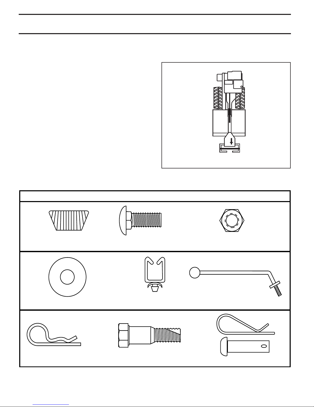
(1) Carriage Bolt
3/8-16 UNC x 1 Gr. 5
(1) Center Locknut
3/8-16 UNC
(2) Handle Lock
(1) Hairpin Clip
(1) Cable Clip
(1) Handle Lock Lever
(1) Flat Washer 13/32 x 1 x 11 Ga.
CONTENTS OF HARDWARE PACK
(1) Pivot Bolt
3/8-16 UNC Grade 5
(2) Shear Pins & Clips
ASSEMBLY
Your new tiller has been assembled at the factory with exception of those parts left unassembled for shipping purposes.
To ensure safe and proper operation of your tiller all parts and hard ware you assemble must be tight ened securely. Use
the correct tools as necessary to insure proper tightness.
TOOLS REQUIRED FOR ASSEMBLY
A socket wrench set will make assembly easier. Stan dard
wrench sizes are listed.
(1) Utility knife
(1) Wire cutter
(1) Screwdriver
(1) Tire pressure gauge
(1) Pair of pliers
(1) 9/16" wrench
OPERATOR’S POSITION (See Fig. 1)
When right or left hand is mentioned in this man ual, it
means when you are in the operating po si tion (standing
behind tiller handles).
LEFT
FRONT
RIGHT
overhead_views_1
OPERATOR’S
POSITION
FIG. 1
4
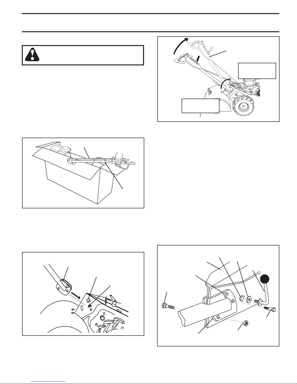
UNPACKING CARTON (See Fig. 2)
ASSEMBLY
CAUTION: Be careful of exposed sta ples
when handling or disposing of cartoning material.
IMPORTANT: WHEN UN PACK ING AND AS SEM BLING
TILLER, BE CAREFUL NOT TO STRETCH OR KINK CABLES.
• While holding handle assembly, cut cable ties se cur ing
handle assembly to top frame. Let handle assembly
rest on tiller.
• Remove top frame of carton.
• Slowly ease handle assembly up and place on top of
carton.
• Cut down right hand front and right hand rear cor ners
of carton, lay side carton wall down.
• Remove packing material from handle assembly.
• Separate shift rod from handle assembly.
SHIFT ROD
carton
_1
HANDLE
AS SEM BLY
FIG. 2
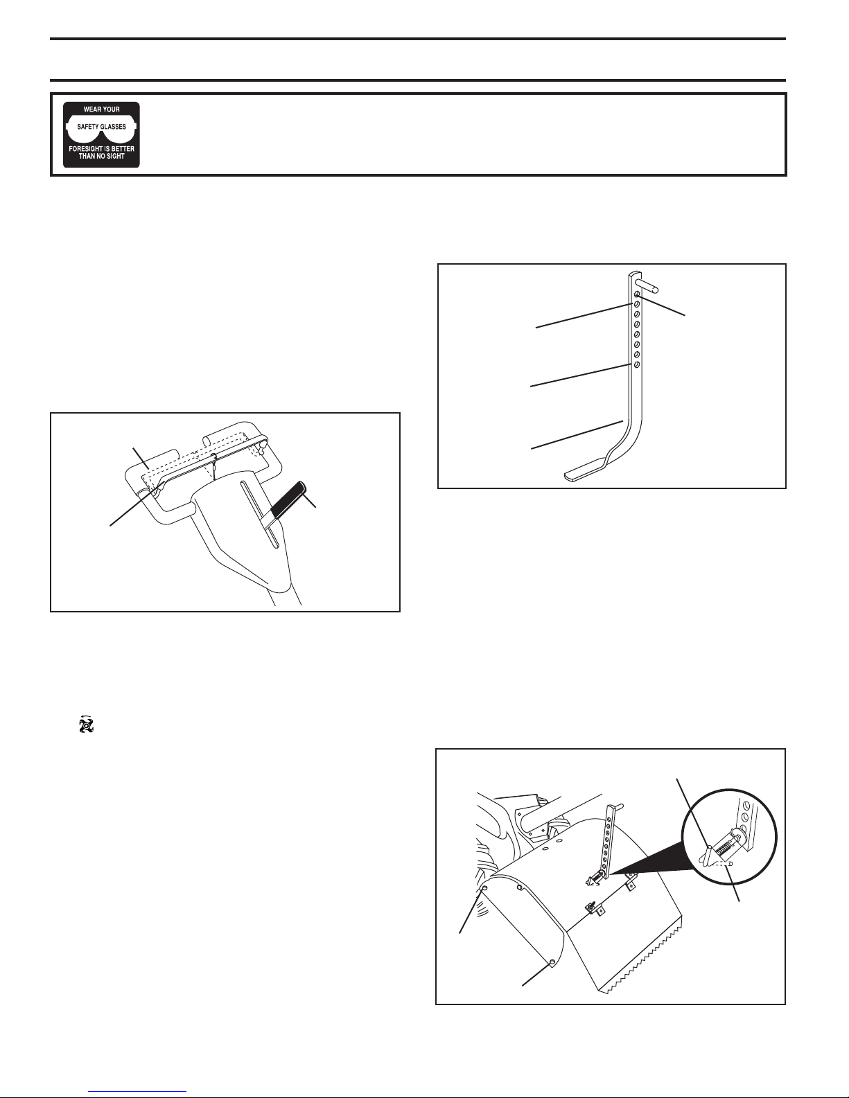
INSTALL HANDLE (See Figs. 3, 4, and 5)
• Insert one handle lock (with teeth facing outward) in
gearcase notch. (Apply grease on smooth side of
handle lock to aid in keeping lock in place until handle
assembly is lowered into position.)
VIEWED FROM R.H. SIDE OF TILLER
HANDLE ASSEMBLY
GEARCASE
NOTCH
HANDLE
LOCK
HANDLE ASSEMBLY
"UP" POSITION
TIGHTEN HANDLE
LOCK LEVER TO
HOLD
LOOSEN HANDLE
LOCK LEVER TO
MOVE
FIG. 4
• Rotate handle assembly down. Insert rear carriage bolt
first, with head of bolt on L.H. side of tiller and loosely
assemble locknut (See Fig. 5).
• Insert pivot bolt in front part of plate and tighten.
• Cut down remaining corners of carton and lay panels
flat.
• Lower the handle assembly. Tighten nut on carriage
bolt so handle moves with some resistance. This will
allow for easier adjustment.
• Place flat washer on threaded end of handle lock le ver.
• Insert handle lock lever through handle base and
gearcase. Screw in handle lock lever just enough to
hold lever in place.
• Insert second handle lock (with teeth inward) in the
slot of the handle base (just inside of washer).
• Raise handle assembly to highest position and se cure ly
tight en handle lock lever by rotating clockwise. Leav ing
han dle assembly in highest position will make it easier
to connect shift rod.
HANDLE
LOCK
GEARCASE
SLOT
REAR
CARRIAGE
BOLT
FLAT
WASHER
HANDLE LOCK
LEVER
FIG. 3
• Grasp handle assembly. Hold in “up” position. Be sure
handle lock remains in gearcase notch. Slide handle
assembly into position.
34
les_
hand
HANDLE
BASE
LOCKNUT
PIVOT
BOLT
FIG. 5
5
ASSEMBLY
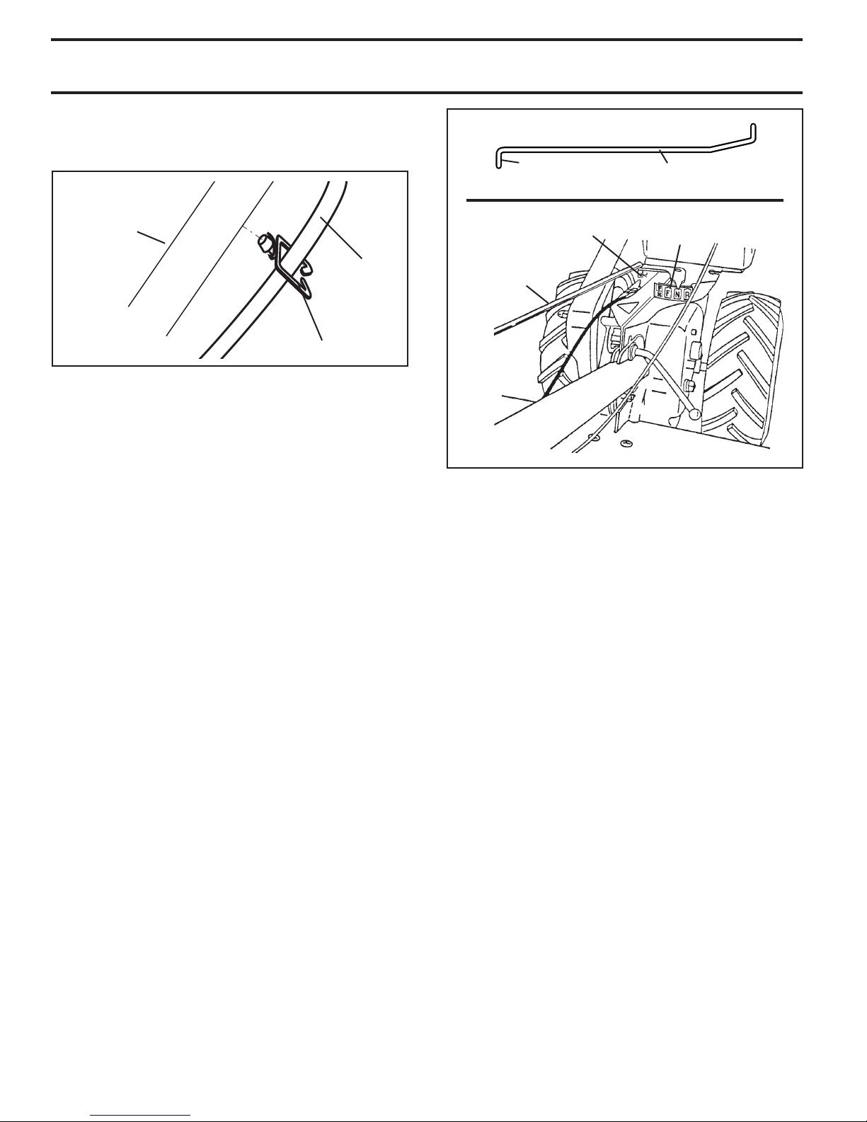
INSERT CABLE CLIP (See Fig. 6)
• Insert plastic cable clip into hole on the back of handle
column. Push cables into clip.
HANDLE
COLUMN
ATTACH THIS END
TO SHIFT LEVER
IN DI CA TOR
HAIRPIN
CLIP
SHIFT ROD
SHIFT
LEVER
INDICATOR
CABLE
CABLE CLIP
FIG. 6
CONNECT SHIFT ROD (See Fig. 7)
• Insert end of shift rod farthest from bend into hole of
shift lever in di ca tor.
• Insert hairpin clip through hole of shift rod to secure
with bend of clip on right side.
REMOVE TILLER FROM CRATE
• Adjust handle assemby to lowest position. Be sure lock
lever is tightened securely.
• Make sure shift lever indicator is in “N” (neutral) po si tion
(See Fig. 7)
• Tilt tiller forward by lifting handle. Separate cardboard
cover from leveling shield.
• Rotate tiller handle to the right and pull tiller out of
carton.
SHIFT
ROD
FIG. 7
CHECK TIRE PRESSURE
The tires on your unit were overinflated at the factory for
shipping purposes. Correct and equal tire pressure is
important for best tilling performance.
• Reduce tire pressure to 20 PSI(1.4 kg/cm2)
HANDLE HEIGHT
• Handle height may be adjusted to better suit operator.
(See “TO ADJUST HANDLE HEIGHT” in the Service
and Adjustments section of this manual).
6
SIDE?VIEWS?
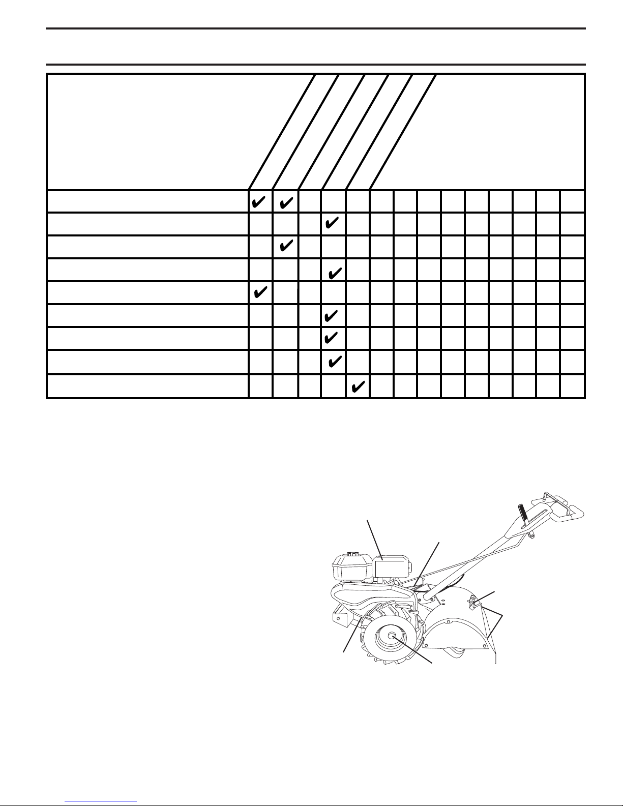
OPERATION
KNOW YOUR TILLER
READ THIS OWNER'S MANUAL AND SAFETY RULES BEFORE OPERATING YOUR TILLER.
Compare the illustrations with your tiller to familiarize yourself with the location of various controls and adjustments. Save
this manual for future reference.
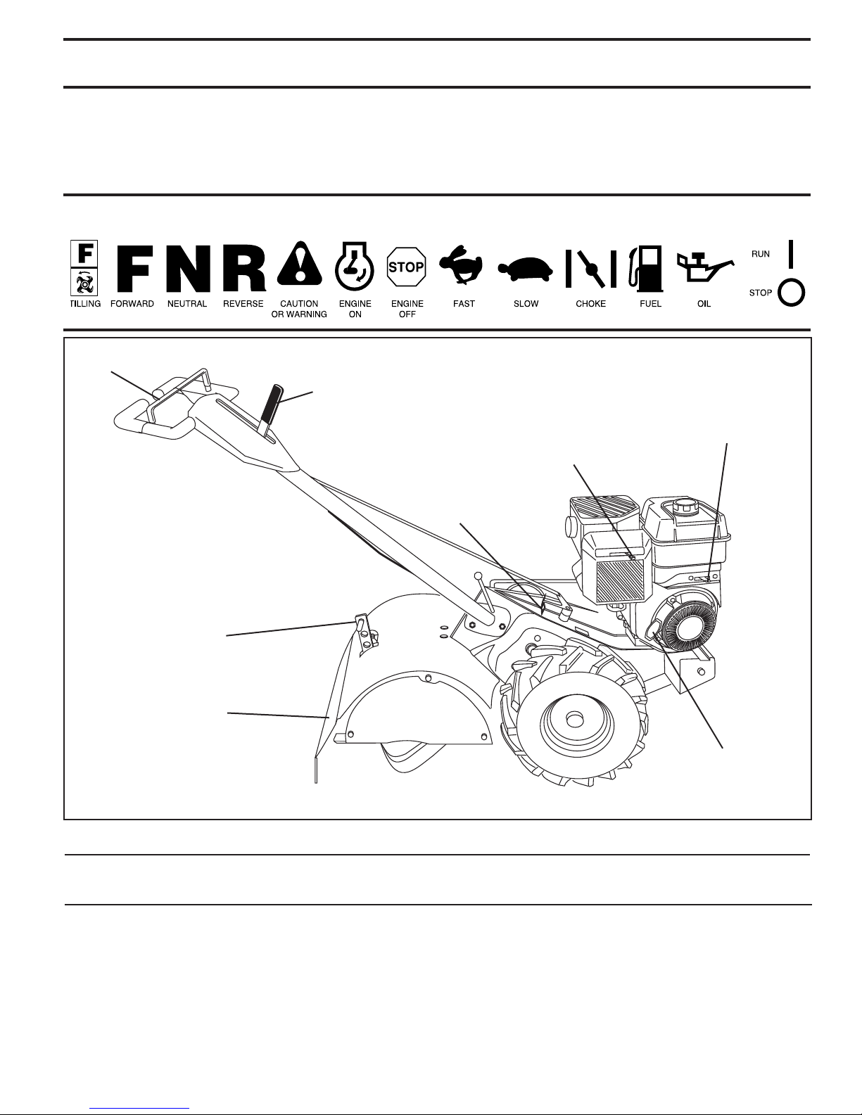
These symbols may appear on your Tiller or in literature supplied with the product. Learn and understand their
meaning.
DRIVE CON TROL
BAR
SHIFT LEVER
THROTTLE
CONTROL
CHOKE CONTROL
SHIFT LEVER
INDICATOR
DEPTH STAKE
LEVELING
SHIELD
FIG. 8
MEETS ANSI SAFETY REQUIREMENTS
Our tillers conform to the safety standards of the American National Standards Institute.
RECOIL
STARTER
HANDLE
CHOKE CONTROL - Used when starting a cold engine.
DEPTH STAKE - Controls depth at which tiller will dig.
DRIVE CONTROL BAR - Used to engage tines.
LEVELING SHIELD - Levels tilled soil.
RECOIL STARTER HANDLE - Used to start the engine.
SHIFT LEVER - Used to shift transmission gears.
SHIFT LEVER INDICATOR - Shows which gear the trans-
mis sion is in.
THROTTLE CONTROL - Controls engine speed.
7
d
e
p
th_stake_2
OPERATION
HANDLES?
The operation of any tiller can result in foreign objects thrown into the eyes, which can result
in severe eye damage. Always wear safety glasses or eye shields before starting your tiller
and while tilling. We recommend a wide vision safety mask for over spectacles or standard
safety glasses.
HOW TO USE YOUR TILLER
Know how to operate all controls before adding fuel and
oil or attempting to start engine.
STOPPING (See Fig. 9)
TINES AND DRIVE
• Release drive control bar to stop movement.
• Move shift lever to “N” (neutral) position.
ENGINE
• Move throttle control to “STOP” position. If equipped
with stop switch, move switch to “STOP” position.
• Never use choke to stop engine.
DRIVE CONTROL BAR
“ENGAGED” PO SI TION
SHIFT
DRIVE CONTROL BAR
“DISENGAGED” PO SI TION
FIG. 9
TINE OPERATION - WITH WHEEL DRIVE
• Always release drive control bar before moving shift
lever into another position.
• Tine movement is achieved by moving shift lever to
( ) till position and engaging drive control bar.
FORWARD - WHEELS ONLY/TINES STOPPED
• Release drive control bar and move shift lever in di ca tor
to “F” (forward) position. Engage drive control bar and
tiller will move forward.
LEVER
DEPTH STAKE (See Fig. 10)
The depth stake can be raised or lowered to allow you more
versatile tilling and cul ti vat ing, or to more easily transport
your tiller.
TRANSPORT
SHALLOWEST
TILLING (CUL TI VAT ING)
DEEPEST
TILLING
DEPTH
STAKE
POSITION
FIG. 10
TILLING (See Fig. 11)
• Release depth stake pin. Pull the depth stake up for
increased tilling depth. Place depth stake pin in hole
of depth stake to lock in position.
• Place shift lever indicator in till position.
• Hold the drive control bar against the handle to start
tilling movement. Tines and wheels will both turn.
• Move throttle control to “FAST” position for deep tilling.
To cultivate, throttle control can be set at any desired
speed, depending on how fast or slow you wish to
cultivate.
IMPORTANT: ALWAYS RELEASE DRIVE CON TROL
BAR BE FORE MOVING SHIFT LEVER INTO AN OTH ER
PO SI TION.
DEPTH STAKE PIN
“RELEASED” POSITION
REVERSE - WHEELS ONLY/TINES STOPPED
• DO NOT STAND DIRECTLY BEHIND TILLER.
• Release the drive control bar.
• Move throttle control to “SLOW” position.
• Move shift lever indicator to “R” (reverse) position.
• Hold drive control bar against the handle to start tiller
movement.
HARD TO SHIFT GEARS
• Briefly engage drive control bar and release or rock tiller
forward and backward until are able to shift gears.
8
NUT “B”
NUT “A”
h_stake_16
pt
de
FIG. 11
“LOCKED”
POSITION
OPERATION
TURNING
• Release the drive control bar.
• Move throttle control to “SLOW” position.
• Place shift lever indicator in “F” (forward) position. Tines
will not turn.
• Lift handle to raise tines out of ground.
• Swing the handle in the opposite direction you wish
to turn, being careful to keep feet and legs away from
tines.
• When you have completed your turn-around, release
the drive control bar and lower handle. Place shift
lever in till position and move throttle control to de sired
speed. To begin tilling, hold drive control bar against
the handle.
OUTER SIDE SHIELDS (See Fig. 11)
The back edges of the outer side shields are slotted so
that the shields can be raised for deep tilling and low ered
for shal low tilling to protect small plants from being buried.
Loosen nut “A” in slot and nut “B”. Move shield to desired
position (both sides). Retighten nuts.
TO TRANSPORT
CAUTION: Before lifting or trans port ing,
allow tiller engine and muffler to cool.
Disconnect spark plug wire. Drain gas o line from fuel tank.
AROUND THE YARD
• Release the depth stake pin. Move the depth stake
down to the top hole for transporting the tiller. Place
depth stake pin in hole of depth stake to lock in position. This prevents tines from scuffing the ground.
• Place shift lever indicator in “F” (forward) position for
transporting.
• Hold the drive control bar against the handle to start
tiller movement. Tines will not turn.
• Move throttle control to desired speed.
AROUND TOWN
• Disconnect spark plug wire.
• Drain fuel tank.
• Transport in upright position to prevent oil leakage.
BEFORE START ING ENGINE
IMPORTANT: BE VERY CAREFUL NOT TO ALLOW DIRT
TO ENTER THE ENGINE WHEN CHECKING OR ADDING
OIL OR FUEL. USE CLEAN OIL AND FUEL AND STORE IN
APPROVED, CLEAN, COVERED CONTAINERS. USE CLEAN
FILL FUNNELS.
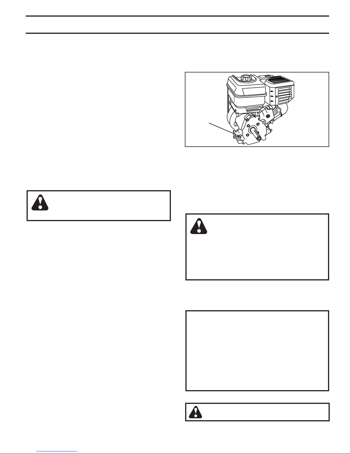
CHECK ENGINE OIL LEVEL (See Fig. 12)
• The engine in your unit has been shipped, from the
factory, already filled with SAE 30 summer weight oil.
• With engine level, clean area around oil filler plug and
remove plug.
• Engine oil should be to point of overflowing when engine
is level. For ap proxi mate capacity see “PROD UCT
SPEC I FI CA TIONS” on page 3 of this manual. All oil
must meet A.P.I. Service Classification SF-SJ.
• Reinstall engine oil cap and tighten.
• For cold weather operation you should change oil for
easier starting (See oil viscosity chart in the Maintenance sec tion of this manual).
• To change engine oil, see the Maintenance section in
this manual.
OIL
FILL
FIG. 12
ADD GASOLINE
• Fill fuel tank to bottom of filler neck. Do not overfill.
Use fresh, clean, regular un lead ed gasoline with a
minimum of 87 octane. (Use of leaded gasoline will
increase carbon and lead oxide deposits and reduce
valve life). Do not mix oil with gasoline. Purchase fuel
in quan ti ties that can be used within 30 days to assure
fuel freshness.
CAUTION: Fill to within 1/2 inch of top
of fuel tank to prevent spills and to allow
for fuel expansion. If gasoline is ac ci den tal ly spilled, move machine away
from area of spill. Avoid creating any
source of ignition until gasoline vapors
have disappeared.
Wipe off any spilled oil or fuel. Do not
store, spill or use gasoline near an
open flame.
IMPORTANT: WHEN OPERATING IN TEMPERATURES
BELOW32°F(0°C), USE FRESH, CLEAN WINTER GRADE
GAS O LINE TO HELP INSURE GOOD COLD WEATHER
START ING.
CAUTION: Alcohol blended fuels (called gas o hol
or using ethanol or methanol) can attract moisture
which leads to sep a ra tion and for ma tion of acids
during storage. Acidic gas can damage the fuel
system of an engine while in storage. To avoid engine problems, the fuel system should be emptied
before stor age of 30 days or longer. Drain the gas
tank, start the engine and let it run until the fuel
lines and carburetor are empty. Use fresh fuel next
sea son. See Storage In struc tions for additional information. Never use engine or carburetor cleaner
products in the fuel tank or permanent damage
may occur.
TO START ENGINE (See Fig. 13)
CAUTION: Keep tine control in “OFF”
position when starting engine.
9
OPERATION
When starting engine for the first time or if engine has run
out of fuel, it will take extra pulls of the recoil starter to move
fuel from the tank to the engine.
• Make sure spark plug wire is prop er ly connected.
• Move shift lever indicator to “N” (neutral) position.
• Place throttle control in “FAST” position.
• Turn fuel shut-off valve to 1/4 turn to OPEN position.
• Push stop switch to “ON” position.
• Move choke control to full “CHOKE” position.
• Grasp recoil starter handle with one hand and grasp
tiller handle with other hand. Pull rope out slowly until
engine reaches start of com pres sion cycle (rope will
pull slightly harder at this point).
• Pull recoil starter handle quickly. Do not let starter
handle snap back against starter.
• If engine fires but does not start, move choke control
to half choke position. Pull recoil starter handle until
engine starts.
• When engine starts, slowly move choke control to
“RUN” position as engine warms up.
NOTE: A warm engine requires less choking to start.
• Move throttle control to desired running position.
• Allow engine to warm up for a few minutes before
engaging tines.
NOTE: If at a high altitude (3000 feet) or in cold tem per a tures
(below 32°F), the carburetor fuel mix ture may need to be
adjusted for best engine per for mance. See “TO AD JUST
CARBURETOR” in the Service and Ad just ments section
of this manual.
NOTE: If engine does not start, see troubleshooting
points.
SPARK PLUG
THROTTLE
CONTROL
CHOKE
CON TROL
engine_
ar
t
_
RECOIL STARTER
71
FIG. 13
TILLING HINTS
CAUTION: Until you are accustomed
to handling your tiller, start actual field
use with throttle in slow position.
• Soil conditions are important for proper tilling. Tines will
not readily penetrate dry, hard soil which may con trib ute
to excessive bounce and difficult handling of your tiller.
Hard soil should be mois tened before tilling; however,
extremely wet soil will “ball-up” or clump during tilling.
Wait until the soil is less wet in order to achieve the
best results. When tilling in the fall, re move vines and
long grass to prevent them from wrapping around the
tine shaft and slowing your tilling operation.
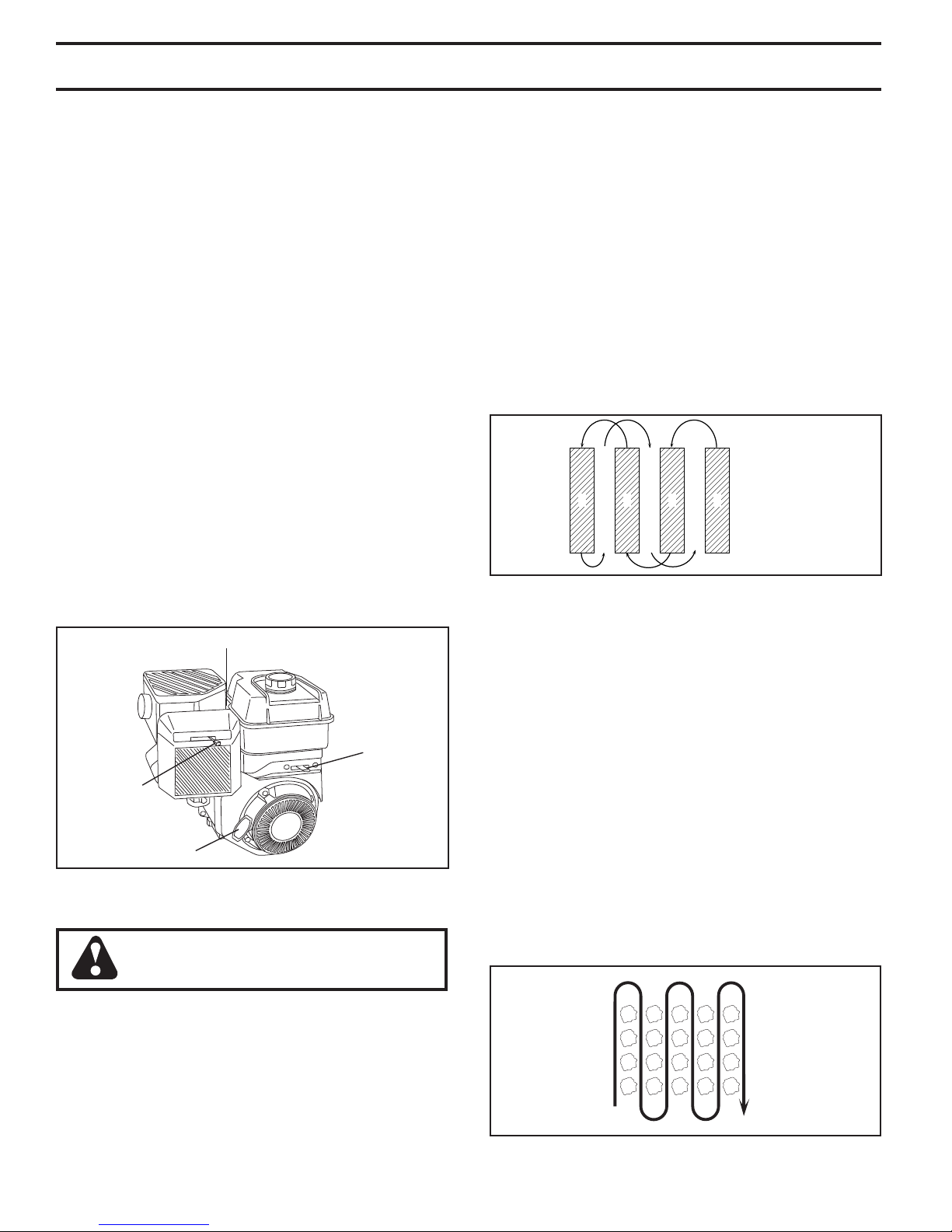
• You will find tilling much easier if you leave a row untilled between passes. Then go back between tilled
rows. (See Fig. 14) There are two reasons for doing
this. First, wide turns are much easier to negotiate than
about-faces. Sec ond, the tiller won’t be pulling itself,
and you, toward the row next to it.
• Do not lean on handle. This takes weight off the wheels
and reduces traction. To get through a really tough
section of sod or hard ground, apply upward pressure
on handle or lower the depth stake.
321
4
67
5
FIG. 14
TINE SHEAR PINS
The tine assemblies on your tiller are secured to the tine
shaft with shear pins (See “TINE REPLACEMENT” in the
Service and Ad just ments section of this manual).
If the tiller is unusually overloaded or jammed, the shear
pins are designed to break before internal damage occurs
to the trans mis sion.
• If shear pin(s) break, replace only with those shown in
the Repair Parts section of this manual.
CULTIVATING
Cultivating is destroying the weeds between rows to pre vent them from robbing nourishment and moisture from the
plants. At the same time, breaking up the upper layer of
soil crust will help retain moisture in the soil. Best digging
depth is 1" to 3" (2.5-7.5 cm). Lower the outer side shields
to protect small plants from being buried.
• Cultivate up and down the rows at a speed which will
allow tines to uproot weeds and leave the ground in
rough condition, promoting no further growth of weeds
and grass (See Fig. 15).
• Tilling is digging into, turning over, and breaking up
packed soil before planting. Loose, unpacked soil helps
root growth. Best tilling depth is 4" to 6"(10-15cm). A
tiller will also clear the soil of unwanted vege ta tion. The
de com po si tion of this vegetable mat ter enriches the
soil. Depending on the climate (rain fall and wind), it
may be advisable to till the soil at the end of the growing season to further condition the soil.
FIG. 15
10
MAINTENANCE
MAINTENANCE
SCHEDULE
FILL IN DATES
AS YOU COMPLETE
REGULAR SERVICE
Check Engine Oil Level
Change Engine Oil
Oil Pivot Points
Inspect Air Screen
Inspect Spark Arrester / Muffler
Clean or Replace Air Cleaner Cartridge
Clean Engine Cylinder Fins
Replace Spark Plug
BEFORE EACH USE
EVERY 25 HOURS
EVERY 5 HOURS
EVERY 50 HOURS
SERVICE DATES
1,2
2
1 - Change more often when operating under a heavy load or in high ambient temperatures.
2 - Service more often when operating in dirty or dusty conditions.
EVERY SEASON
RH Gear Case Grease Fitting (1oz.)
GENERAL RECOMMENDATIONS
The warranty on this tiller does not cover items that have
been subjected to operator abuse or negligence. To receive
full value from the warranty, the operator must main tain tiller
as instructed in this manual.
Some adjustments will need to be made periodically to
properly maintain your tiller.
All adjustments in the Service and Adjustments section
of this manual should be checked at least once each
season.
• Once a year you should replace the spark plug, clean
or replace air filter, and check tines and belts for wear.
A new spark plug and clean air filter assure proper
air-fuel mixture and help your engine run better and
last longer.
BEFORE EACH USE
• Check engine oil level.
• Check tine operation.
• Check for loose fasteners.
LUBRICATION
Keep unit well lubricated (See “LUBRICATION CHART”).
LUBRICATION CHART
d ENGINE
eRH GEAR CASE
GREASE FIT TING
c DEPTH
STAKE PIN
c IDLER
BRACKET
cSAE 30 OR 10W-30 MOTOR OIL
dREFER TO MAINTENANCE “ENGINE” SECTION
eEP #1 GREASE
c WHEEL
HUB
c LEVELING
SHIELD
HINGES
11
 Loading...