

Craftsman 944609900 Owner’s Manual
SEARS
OWNER'S
MANUAL
MODEL NO.
944.609900
CRRFTSMU
Caution:
Read and follow
all Safety Rules
and Instructions
Before Operating
This Equipment
20.0 HP
ELECTRIC START
46" MOWER
AUTOMATIC
GARDEN TRACTOR
• Assembly
• Operation
• Customer Responsibilities
• Service and Adjustments
• Repair Parts
Sears Canada, Inc., Toronto, Ontario M5B 2B8
Safe Operation Practices for Ride-On Mowers
IMP_)RTANT: THIS CU']-FING MACHINE IS CAPABLE OF AMPUTATING HANDS AND FEET AND THROWING
OBJECTS. FAILURE TO OBSERVE THE FOLLOWING SAFETY INSTRUCTIONS COULD RESULT IN SERIOUS
INJURY OR DEATH.
I. GENERAL OPERATION
Read, understand, and follow all instructions in the manual
and on the machine before starting.
Only allow responsible adults, who are familiar with the
instructions, to operate the machine.
• Clear the area of ob acts such as recks, toys, wire, etc.,
which could be picked up and thrown by the bade.
• Be sure the areais clear ofotherpeople before mowing. Stop
machine if anyone enters the area.
Never carry passengers.
Donot mow in reverse unless absolutely necessary. Always
look down and behind before and while backing.
Be aware of the mower discharge direction and do not point
it at anyone. Do not operate the mower without either the
entire grass catcher or the guard in place.
Slow down before turning.
Never leave a runningmachine unattended. Always turn off
blades, set parking brake, stop engine, and remove keys
before dismounting.
Tum off blades when not mowing.
Stop engine before removing grass catcher or unclogging
chute,
Mow only in daylight or good artificial light.
Do not operate the machine while under the influence of
alcohol or drugs.
Watch fortrafficwhen operating near or crossing roadways.
• Use extra care when loading or unloading the machine into
a trailer or truck.
II. SLOPE OPERATION
Slopes are a major factor related to loss-of-control and tipover
accidents, which can result in severe injury or death. All slopes
require extra caution. If you cannot back upthe slope or ifyoufeel
uneasy on it, do not mow it.
DO:
Mow up and down slopes, not across.
Remove obstacles such as recks, tree limbs, etc.
Watch for holes, ruts, or bumps. Uneven terrain could
overturn the machine. Tall grass can hide obstacles.
• Use slow speed. Choose a low gear so that you willnot have
to stop or shift while on the slope.
Follow the manufacturer's recommendations for wheel
weights or counterweights to improve stability.
Usa extra care with grass catchers or other attachments.
These can change the stability of the machine.
Keep all movement on the slopes slowand gradual. Do not
make sudden changes in speed or direction.
Avoid starting orstopping on a slope. If tires lose traction,
disengage the blades and proceed slowly straight down the
slope.
DO NOT:
Do not turnon slopes unless necessary, end then, turnslowly
and gradually downhill, ifpossible.
Do not mow near drop-offs, ditches, or embankments. The
mower could suddenly turn over if a wheel is over the edge
of a cliff or ditch, or it an edge caves in.
Do not mow on wet grass. Reduced traction could cause
sliding•
• Do not try to stabilize the machine by puttingyourfoot on the
ground.
Do not use grass catcher on steep slopes.
SAFETY RULES A
IlL CHILDREN
Tragic accidentscan occur if the operatoris not alert to the
presenceofchildren.Childrenareoftenattracted tothemachine
andthemowingactivity. Neverassumethat childrenwillremain
whereyoulastsawthem.
• Kaspchildranoutofthemowingarea andunderthewatchful
careof anotherresponsibleadult.
Be alertand tum machineofti| childrenenterthearea.
Beforeand when backing,lookbehind and downforsmall
children.
Never carrychildren. They may fall off and be seriously
injuredorintederewithsafemachineoperation.
• Neverallowchildrentooperatethe machine.
Use extra care when approachingblind comers, shrubs,
trees,or otherobjectsthatmay obscurevision.
IV. SERVICE
• Usaextracareinhandlinggasolineandotherfuels.Theyare
flammableand vaporsare explosive.
Useonlyanapprovedcontainer.
Never remove gas cap or add fuel with the engine
running. Allowenginetocoolbeforerefueling.Do not
smoke.
Neverrefuelthe machineindoors.
Neverstorethemachineorfuel containerinsidewhere
thereisan openflame, suchasa water heater.
• Neverruna machineinsidea closedarea.
• Keepnutsandbolts,especiallybladeattachmentbolts,tight
and keepequipmentingoodcondition.
Never tamper with safety devices. Check their proper
operationregularly.
Keepmachinefree ofgrass,leaves,orotherdebrisbuild-up.
Clean oil or fuel spillage. Allow machineto cool before
storing.
Stop and inspectthe equipmentif you strike an object.
Repair,if necessary,beforerestarting.
Nevermakeadjustmentsor repairswiththeenginerunning.
• Grasscatchercomponentsaresubecttowear,damage,and
deterioration,which could expose movng parts or a ow
objectsto be thrown. Frequentlycheckcomponentsand
replacewithmanufacturer'srecommendedparts,whennec-
essary.
• Mowerbladesare sharpandcan cut. Wrapthe blade(s)or
weargloves,and usa extracautionwhenservicingthem.
Check brake operationfrequently. Adjustand serviceas
required.
Look for this symbol to point out impor-
tant safety precautions. It means
CAUTIONI!! BECOME ALERT!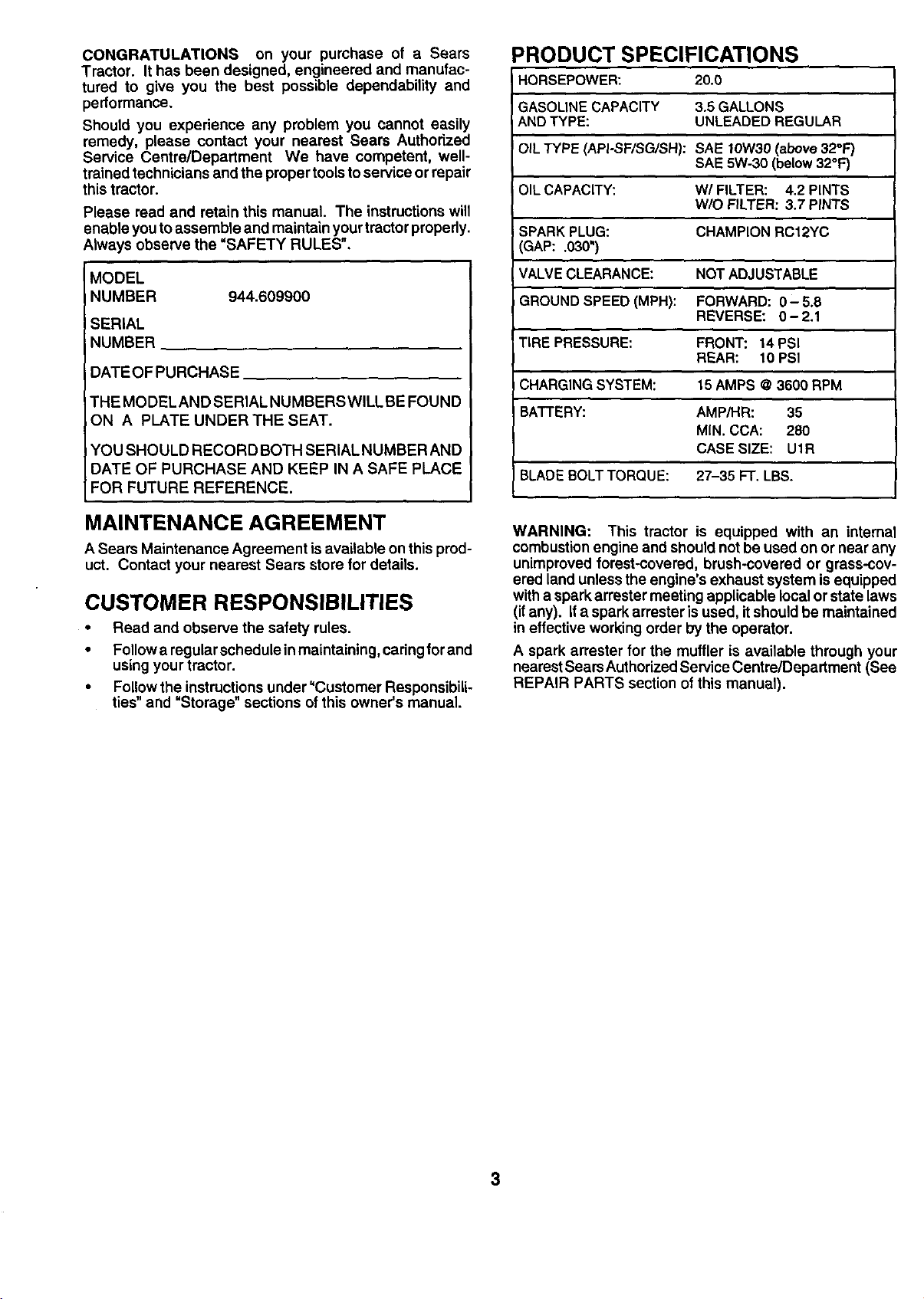
CONGRATULATIONS on your purchase of a Sears
Tractor. It has been designed, engineered and manufac-
tured to give you the best possible dependability and
pedormance.
Should you experience any problem you cannot easily
remedy, please contact your nearest Sears Authorized
Service Centre/Department We have competent, well-
trained technicians and the proper toolsto service or repair
this tractor.
Please read and retain this manual. The instructionswill
enable you to assemble and maintain your tractor properly.
Always observe the "SAFETY RULES",
MODEL
NUMBER 944.609900
SERIAL
NUMBER
DATEOFPURCHASE
THE MODEL AND SERIAL NUMBERS WILL BE FOUND
ON A PLATE UNDER THE SEAT.
YOU SHOULD RECORD BOTH SERIAL NUMBER AND
DATE OF PURCHASE AND KEEP IN A SAFE PLACE
FOR FUTURE REFERENCE.
PRODUCT SPECIFICATIONS
HORSEPOWER: 20.0
GASOLINECAPACITY 3.5 GALLONS
ANDTYPE: UNLEADED REGULAR
iOIL TYPE (API-SF/SG/SH): SAE t0W30 (above 32°F'/
SAE 5W-30 (below 32°F)
OILCAPACITY: W/FILTER: 4.2 PINTS
W/O FILTER: 3.7 PINTS
SPARK PLUG: CHAMPION RC12YC
3AP: .030")
VALVE CLEARANCE: NOT ADJUSTABLE
GROUND SPEED (MPH): FORWARD: 0- 5,8
REVERSE: 0-2.1
TIRE PRESSURE: FRONT: 14 PSI
REAR: 10 PSI
CHARGINGSYSTEM: t 5 AMPS @ 3600 RPM
BATTERY: AMP/HR: 35
MIN. CCA: 280
CASE SIZE: U1R
BLADEBOLT TORQUE: 27-35 FT. LBS.
MAINTENANCE AGREEMENT
A Sears Maintenance Agreement is available onthis prod-
uct. Contact your nearest Sears store for details.
CUSTOMER RESPONSIBILITIES
• Read and observe the safety rules.
• Follow a regularschedule inmaintaining, cadngfor and
using your tractor.
• Followthe instructions under"Customer Responsibili-
ties" and =Storage" sections ofthis owner's manual.
WARNING: This tractor is equipped with an internal
combustionengine and shouldnot be used onor near any
unimproved forest-covered, brush-covered or grass-cov-
ered land unless the engine's exhaust system is equipped
witha spark arrester meeting applicable local or state laws
(ifany). If a spark arrestar is used, it shouldbe maintained
in effective working order by the operator.
A spark arrester for the muffler is available through your
nearest SearsAuthorized Service Centre/Depadment (See
REPAIR PARTS section of this manual).
3

TABLE OF CONTENTS
SAFETY RULES ............................................................ 2
PRODUCT SPECIFICATIONS ...................................... 3
CUSTOMER RESPONSIBILITIES ..................... 3, 16-19
WARRANTY .................................................................. 4
ASSEMBLY .......................................................... ,.... 6-9
OPERATION ........................................................... 10-15
MAINTENANCE SCHEDULE ...................................... 16
SERVICE AND ADJUSTMENTS ............................ 20-26
STORAGE ................................................................... 27
TROUBLESHOOTING ............................................ 28-29
REPAIR PARTS - TRACTOR ................................. 32-49
REPAIR PARTS - ENGINE .................................... 50-57
PARTS ORDERING/SERVICE ................ BACK COVER
LIMITED TWO (2) YEAR WARRANTY ON CRAFTSMAN TRACTOR (RIDING EQUIPMENT)
For two (2) years from date of purchase Sears Canada, Inc. will repairor replace at Sears option free of charge parts which are
defective as a result of matedal or workmanship.
FULL ONE (1) YEAR WARRANTY ON BAI-I'ERY
For one (t) year from date of purchase, if any battery included with this riding equipment proves defective in matedal or
workmanship and our testing determines the battery will not hold a charge, Sears will replace the battery at no charge.
COMMERCIAL OR RENTAL USE
Warranty on Riding Equipment used for commercial or rental purposes is limitedto ninety (90) days.
This Warranty does NOT cover:
1. Pre-delivery set-up.
2. Tire replacement or repair caused by punctures from outside objects (such as nails, thorns, stumps, or glass).
3. Expendable items which become worn dudng normal use, such as blades, spark plug, air cleaners and belts.
4. Repairs necessary because of operator abuse or negligence, including damaged jackshaft or mandrel and the
failure to operate and maintain the equipment according to the instructions contained In the Owner's Manual.
5. In Home service.
Warranty service is available by returning the Craftsman Riding Equipment to the nearest Sears Service Centre/Department in
Canada. This warranty applies onlywhile this product is in use inCanada.
This warranty is in addition to any statutory warranty and does not exclude or limit legal dghts you may have but shall run
concurrentlywith applicable provincial legislation. Furthermore, some provinces do NOT allow limitationon how long an implied
warranty will last sothe above limitationsmay not apply to you.
SEARS CANADA, INC., TORONTO, ONTARIO M5B 2B8
4
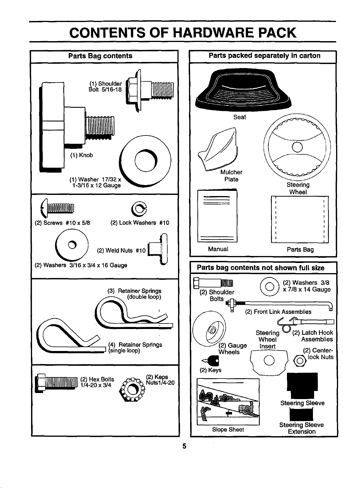
CONTENTS OF HARDWARE PACK
Parts Bag contents
(1) Shoulder
Bolt 5/16-18
m
(1) Knob
©
(1) Washer 17/32
1-3/16 x 12 Gauge
(2) Screws #10 x 518 (2) Lock Washers #10
Parts packed separately in carton
Seat
Mulcher
Plate
Steering
Wheel
(2)Weld Nuts #10_
(2) Washers 3/16 x 3/4 x 16 Gauge
(3) Retainer Springs
_ _ J 14) Retainer Springs
I (single loop)
1/4-20 x 3/4 Nuts114-20
_(2) Hex Bolts _(2) Keps
I
Manual Parts Bag
Parts bag contents not shown full size
_ (2)Washers 3/8
(2) Shoulder _ x 7/8 x 14 Gauge
Bolts
_J (2) Front Link Assemblies
¢" L_% ii
Steering'-O--((2) Latch Hook
Wheel Assemblies
Gauge Insert
Wheels /-----------3 (2) Center-
,4= @,ookNuts
(2) Keys
Steering Sleeve
Slope Sheet
Steering Sleeve
Extension
5
ASSEMBLY
Your new tractor has been assembled at the factory with exception of those parts left unassembled for shipping purposes.
To ensgre safe and proper operation of your tractor all parts and hardware you assemble must be tightened securely. Use
the correct tools as necessary to insure proper tightness.
TOOLS REQUIRED FOR ASSEMBLY
A socket wrench set will make assembly easier. Standard
wrench sizes are listed.
(2) 7/16" wrenches (1) Tire pressure gauge
(1) 9/16" wrench (1) Utility knife
(1) 1/2" wrench (1) 3/4" socket w/drive ratchet
(1) Pliers (1) PhillipsScrewddver
When right or left hand is mentioned in this manual, it
means when you are in the operating position (seated
behind the steering wheel).
TO REMOVE TRACTOR FROM CARTON
I_1 _/STEEr'NGWHEEL
STEERING
WHEEL ----.........,,_ JABS
_..___F._ INSERT
_,._--.--- HEX BOLT
_ LOCK WASHER
@_ TEERING
WHEEL
UNPACK CARTON
• Remove all accessible loose parts and parts cartons
from carton (See page 5).
• Cut, from top to bottom, along lineson allfour corners
of carton, and lay panels flat.
• Remove mower and packing materials.
• Check for any additional loose parts or cartons and
remove.
BEFORE ROLLING TRACTOR OFF SKID
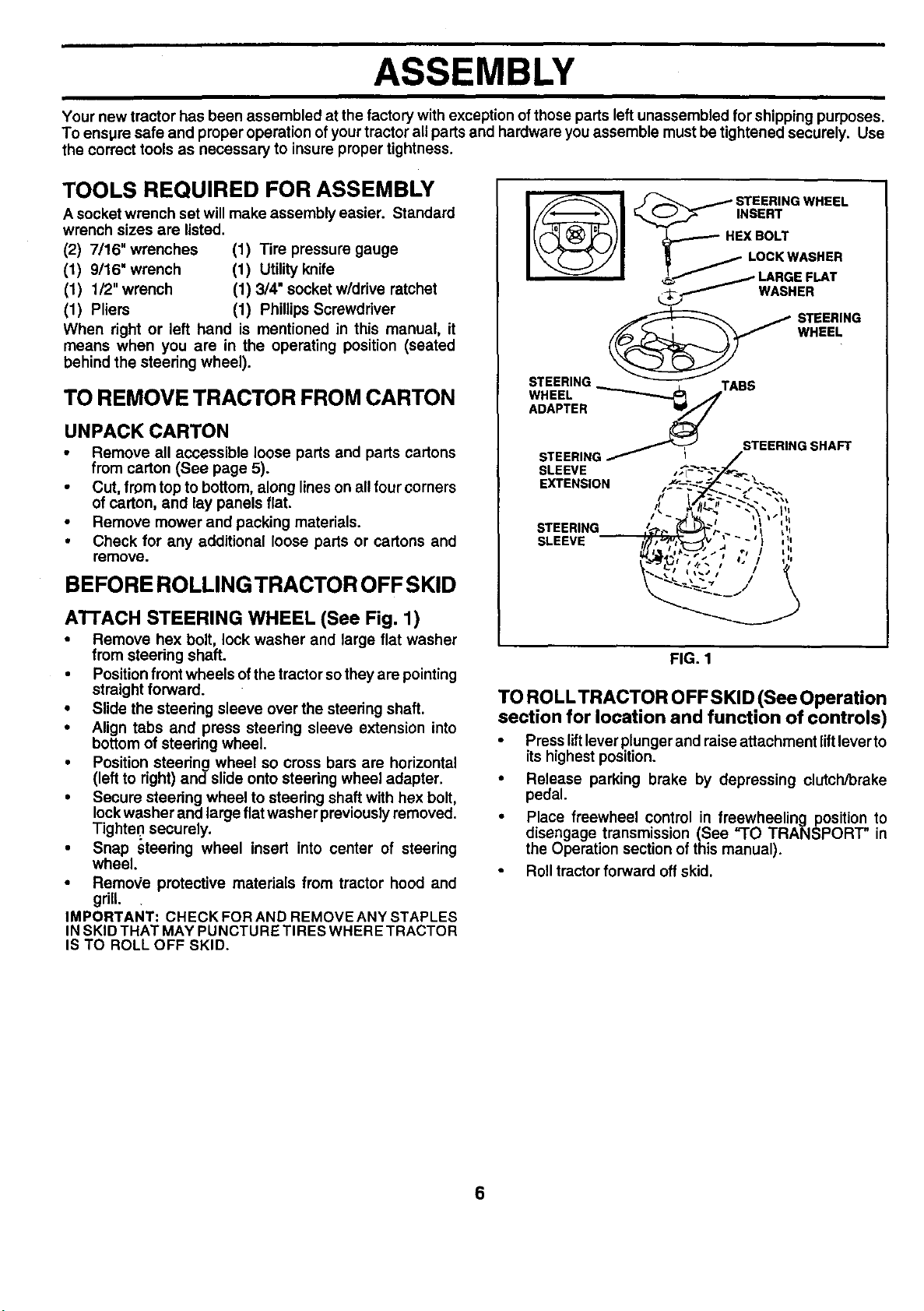
ATTACH STEERING WHEEL (See Fig. 1)
• Remove hex bolt, lock washer and large flat washer
from steering shaft.
• Positionfront wheels of thetractor sothey are pointing
straight forward.
• Slide the steering sleeve over the steering shaft.
• Align tabs and press steering sleeve extension into
bottom of steering wheel.
• Position steering wheel so cross bars are horizontal
(left to right) and slide onto steering wheel adapter.
• Secure steering wheel to steering shaft with hex bolt,
lockwasher and large flatwasher previouslyremoved.
Tighten securely.
• Snap steedng wheel insert into center of steering
wheel.
• RemoVe protective materials from tractor hood and
grill.
IMPORTANT: CHECKFORAND REMOVEANY STAPLES
IN SKID THAT MAY PUNCTURE TIRES WHERE TRACTOR
IS TO ROLL OFF SKID.
ADAPTER _
STEERING _- I
SLEEVE
EXTENSION
STEERING
SLEEVE
FIG. 1
TO ROLLTRACTOR OFF SKID (See Operation
section for location and function of controls)
• Press lift leverplunger and raise attachment lift lever to
its highest position.
• Release parking brake by depressing clutch/brake
pedal.
• Place freewheel control in freewheelingposition to
disengage transmission (See "TO TRANSPORT" in
the Operation section of this manual).
Roll tractor forward off skid.
STEERING SHAFT
%\*1
6
ASSEMBLY
HOW TO SET UP YOUR TRACTOR
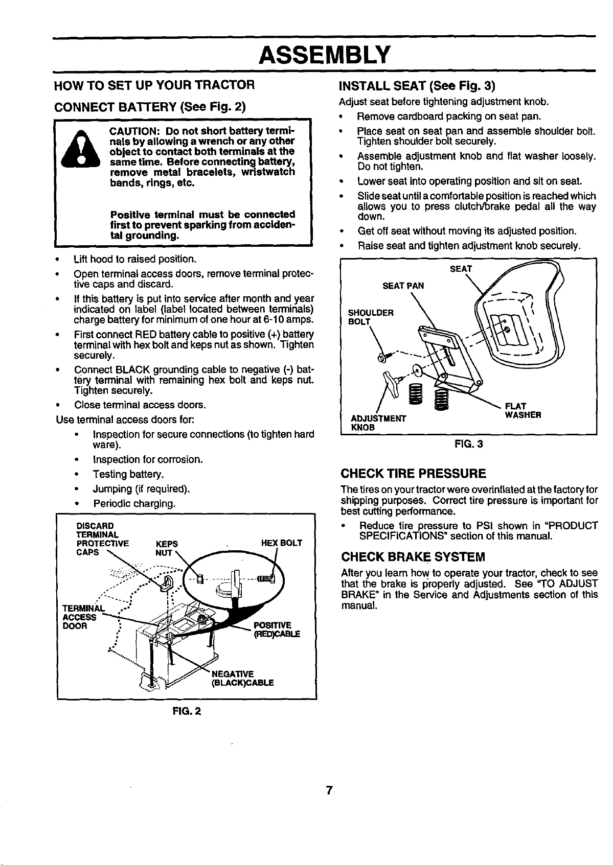
CONNECT BATTERY (See Fig. 2)
CAUTION: Do not short battery termi-
nals by allowing a wrench or any other
object to contact both terminals at the
same time. Before connecting battery,
remove metal bracelets, wristwatch
bands, rings, etc.
Positive terminal must be connected
first to prevent sparking from acciden-
tal grounding.
• Lift hood to raised position.
• Open terminal access doors, remove terminal protec-
tive caps and discard.
• If this battery is put into service after month and year
indicated on label (label located between terminals)
charge battery for minimum ofone hour at 6-10 amps.
• First connect RED battery cable to positive (+) battery
terminal with hex bolt and keps nutas shown. Tighten
securely,
• Connect BLACK grounding cable to negative (-) bat-
tery terminal with remaining hex bolt and keps nut.
Tighten securely.
• Close terminal access doors.
Use terminal access doors for:
• Inspection for secure connections (to tighten hard
ware).
• Inspection for corrosion.
• Testing battery.
• Jumping (if required).
• Periodic charging.
DISCARD
TERMINAL
PROTECTIVE KEPS HEX BOLT
...._,,:y , o"
TERM,N;,i.:J i
ACCESS
DOOR .: _ _'F_.mm_ posrrlvs
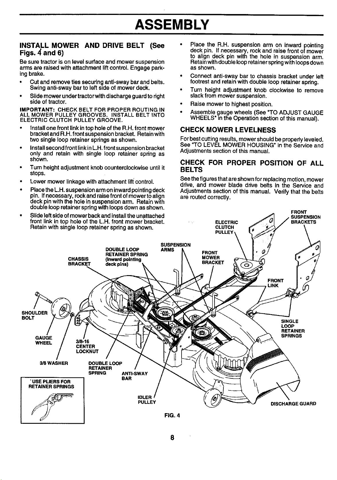
INSTALL SEAT (See Fig. 3)
Adjust seat before tightening adjustment knob.
• Remove cardboard packing on seat pan.
• Place seat on seat pan and assemble shoulder bolt.
Tighten shoulder bolt securely.
• Assemble adjustment knob and flat washer Ioossty.
Do not tighten.
• Lower seat into operating position and sit on seat.
• Slide seat untila comfortable positionis reached which
allows you to press clutch/brake pedal all the way
down.
• Get off seat without moving its adjusted position.
• Raise seat and tighten adjustment knob securely.
SEAT
SEATPAN
SHOULDER
BOLT
. FLAT
ADJUSTMENT
KNOB
FIG. 3
WASHER
CHECK TIRE PRESSURE
The tires on yourtractor were ovefinflated at the factoryfor
shipping purposes. Correct tire pressure is important for
best cutting performance.
• Reduce tire pressure to PSI shown in "PRODUCT
SPECIFICATIONS" section of this manual.
CHECK BRAKE SYSTEM
After you learn how to operate your tractor, check to see
that the brake is properly adjusted. See "TO ADJUST
BRAKE" in the Service and Adjustments section of this
manual.
2'_'%"-..., j
. GATIVE
FIG. 2
7
ASSEMBLY
INSTALL MOWER AND DRIVE BELT (See
Figs. 4 and 6)
Be sure tractor ison level surface and mower suspension
arms are raised with attachment liftcontrol. Engage park-
ing brake.
• Cut and remove ties securing anti-sway bar and belts.
Swing anti-sway bar to left side of mower deck.
• Slide mower undertractorwith discharge guard to right
side of tractor.
IMPORTANT: CHECK BELT FOR PROPER ROUTING IN
ALL MOWER PULLEY GROOVES. INSTALL BELT INTO
ELECTRIC CLUTCH PULLEY GROOVE.
• Install one front linkin top hole ofthe R.H. front mower
bracket and R.H. front suspension bracket. Retain with
two single loop retainer springs as shown.
• Installsecond front linkinL.H. front suspension bracket
only and retain with single loop retainer spring as
shown.
• Turn height adjustment knob counterclockwise until it
stops.
• Lower mower linkage with attachment liftcontrol.
• Place the L.H.suspension arm on inward pointingdeck
pin. Ifnecessary, rockand raise front of mower to align
deck pin with the hole insuspension arm. Retain with
double loop retainer spring with loops down as shown.
• Slide leftside of mower back and installthe unattached
front link in top hole of the LH. front mower'bracket.
Retain with single loop retainer spring as shown.
Place the R.H. suspension arm on inward pointing
deck pin. If necessary, rock and raise front of mower
to align deck pin with the hole in suspension arm.
Retainwithdouble loop retainer springwithloopsdown
as shown.
• Connect anti-sway bar to chassis bracket under left
footrest and retain with double loop retainer spring.
• Turn height adjustment knob clockwise to remove
slack from mower suspension.
• Raise mower to highest position.
• Assemble.gauge wheels (See "TO ADJUST GAUGE
WHEELS in the Operation section of this manual).
CHECK MOWER LEVELNESS
For best cutting results, mower shouldbe properly leveled.
See "TO LEVEL MOWER HOUSING" in the Service and
Adjustments section of this manual.
CHECK FOR PROPER POSITION OF ALL
BELTS
See thefigures that are shownfor replacing motion, mower
drive, and mower blade drive belts in the Service and
Adjustments section of this manual. Verify that the belts
are routed correctly.
FRONT
ELECTRIC
CLUTCH
PULLEY'
SUSPENSION
BRACKETS
SHOULDER
BOLT
GAUGE
WHEEL
3_WASHER
"USE PLIERS FOR
RETAINERSPRINGS
DOUBLE LOOP
RETAINER SPRING
CHASSIS (Inward pointing
BRACKET deck plns)
3/8-16
CENTER
LOCKNUT
DOUBLELOOP
RETAINER
SPRING ANTI-SWAY
BAR
IDLER
PULLEY
SUSPENSION
ARMS
FRONT
MOWER
BRACKET
SINGLE
LOOP
RETAINER
SPRINGS
DISCHARGE GUARD
FIG. 4
8
ASSEMBLY
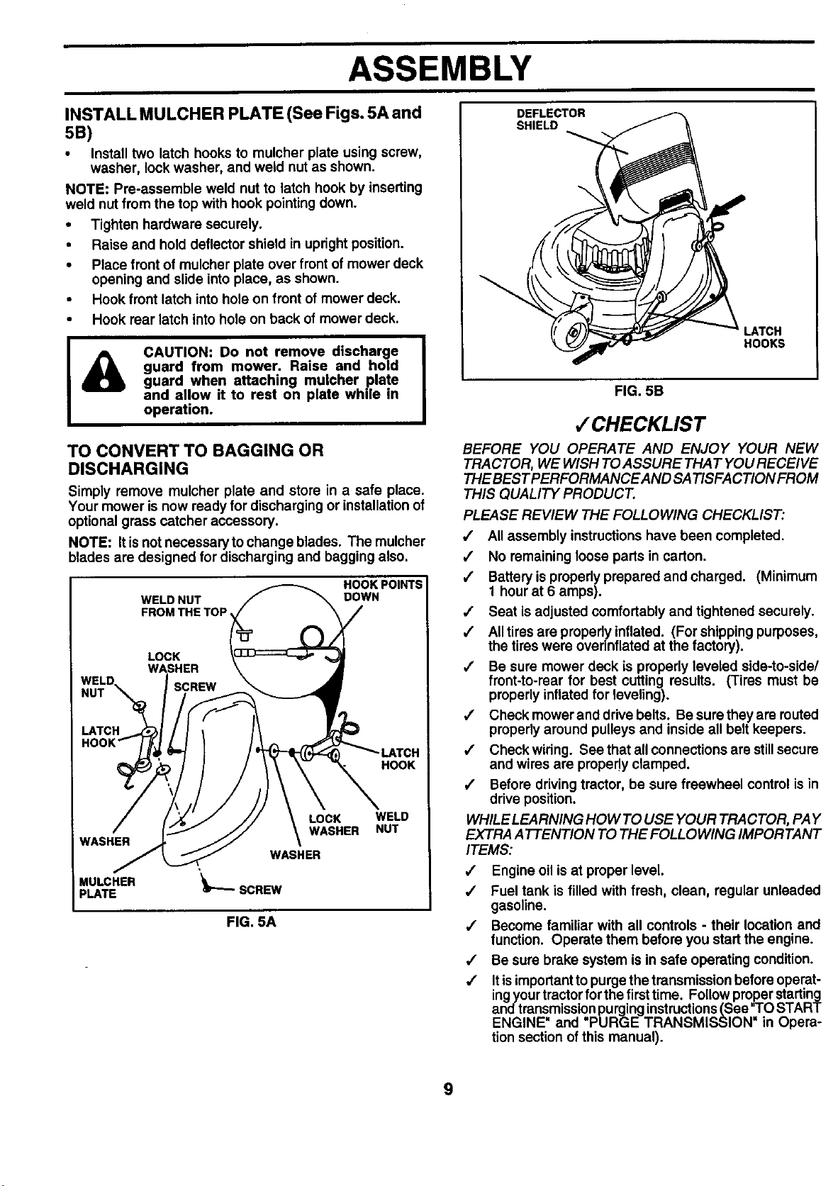
INSTALL MULCHER PLATE (See Figs. 5A and
5B)
• Install two latch hooks to mulcher plate using screw,
washer, lock washer, and weld nut as shown.
NOTE: Pre-assemble weld nut to latch hook by inserting
weld nut from the top with hook pointing down.
• Tighten hardware securely.
• Raise and hold deflector shield in upright position.
• Place front of mulcher plate over front of mower deck
opening and slide into place, as shown.
• Hook front latch intohole on front of mower deck.
• Hook rear latch into hole on back of mower deck.
CAUTION: Do not remove discharge
&
TO CONVERT TO BAGGING OR
DISCHARGING
Simply remove mulcher plate and store in a safe place.
Your mower is now ready for discharging or installation of
optional grass catcher accessory.
NOTE: It isnot necessaryto change blades. The mulcher
blades are designed for discharging and bagging also.
LATCH
WASHER
MULCHER
PLATE
guard from mower. Raise and hold
guard when. attaching mulcher p.late.
and allow it to rest on plate while m
operation.
HOOK POINTS
WELD NUT
FROM THE TOP
LOCK
WASHER
ISCREW
WASHER
'_'_SCREW
FIG. 5A
DOWN
LOCK
WASHER
HOOK
WELD
NUT
DEFLECTOR
SHIELD
LATCH
HOOKS
FIG. 5B
,/CHECKLIST
BEFORE YOU OPERATE AND ENJOY YOUR NEW
TRACTOR, WE WISH TO ASSURE THAT YOU RECEIVE
THE BEST PERFORMANCE AND SATISFA CTION FROM
THIS QUALITY PRODUCT.
PLEASE REVIEW THE FOLLOWING CHECKLIST:
/ All assembly instructions have been completed.
/ No remaining loose parts in carton.
,,1 Battery is properly prepared and charged. (Minimum
1 hour at 6 amps).
,/ Seat is adjusted comfortably and tightened securely.
,/ Alltires are properly inflated. (For shipping purposes,
the tires were ovednflated at the factory).
/ Be sure mower deck is properly leveled side-to-side/
front-to-rear for best cutting results. (Tires must be
properly inflated for leveling).
,/ Check mower and drive belts. Be surethey are routed
properly around pulleys and inside all belt keepers.
,/ Check wiring. See that allconnections are stillsecure
and wires are properly clamped.
,/ Before drivingtractor, be sure freewheel control is in
drive position.
WHILE LEARNING HOW TO USE YOUR TRACTOR, PAY
EXTRA ATTENTION TO THE FOLLOWING IMPORTANT
ITEMS:
/ Engine oil isat proper level.
,/ Fuel tank is filled with fresh, clean, regular unleaded
gasoline.
/ Become familiar with all controls - their location and
function. Operate them before you start the engine.
,/ Be sure brake system is in safe operating condition.
,/ Itis importantto purge the transmission before operat-
ingyour tractorfor the firsttime. Followproper starting
and transmissionpurginginstructions(See"TO START
ENGINE' and "PURGE TRANSMISSION" in Opera-
tionsection of this manual).
9
OPERATION
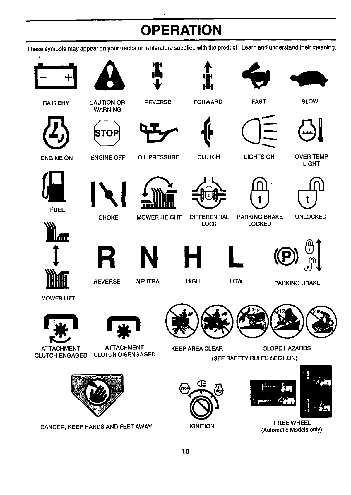
These symbols may appear on your tractor or in literaturesupplied withthe product. Learn and understand their meaning.
BATTERY CAUTION OR REVERSE FORWARD FAST SLOW
WARNING
ENGINE ON ENGINE OFF OIL PRESSURE CLUTCH
FUEL
CHOKE MOWER HEIGHT DIFFERENTIAL PARKING BRAKE UNLOCKED
LOCK LOCKED
! R N H L
_1_ REVERSE NEUTRAL HIGH LOW
MOWER LIFT
LIGHTS ON OVER TEMP
LIGHT
PARKING BRAKE
ATTACHMENT
CLUTCH ENGAGED
DANGER, KEEP HANDS AND FEET AWAY
ATTACHMENT KEEP AREA CLEAR SLOPE HAZARDS
CLUTCH DISENGAGED (SEE SAFETY RULES SECTION)
IGNITION
10
FREEWHEEL
(Automatic Models only)
OPERATION
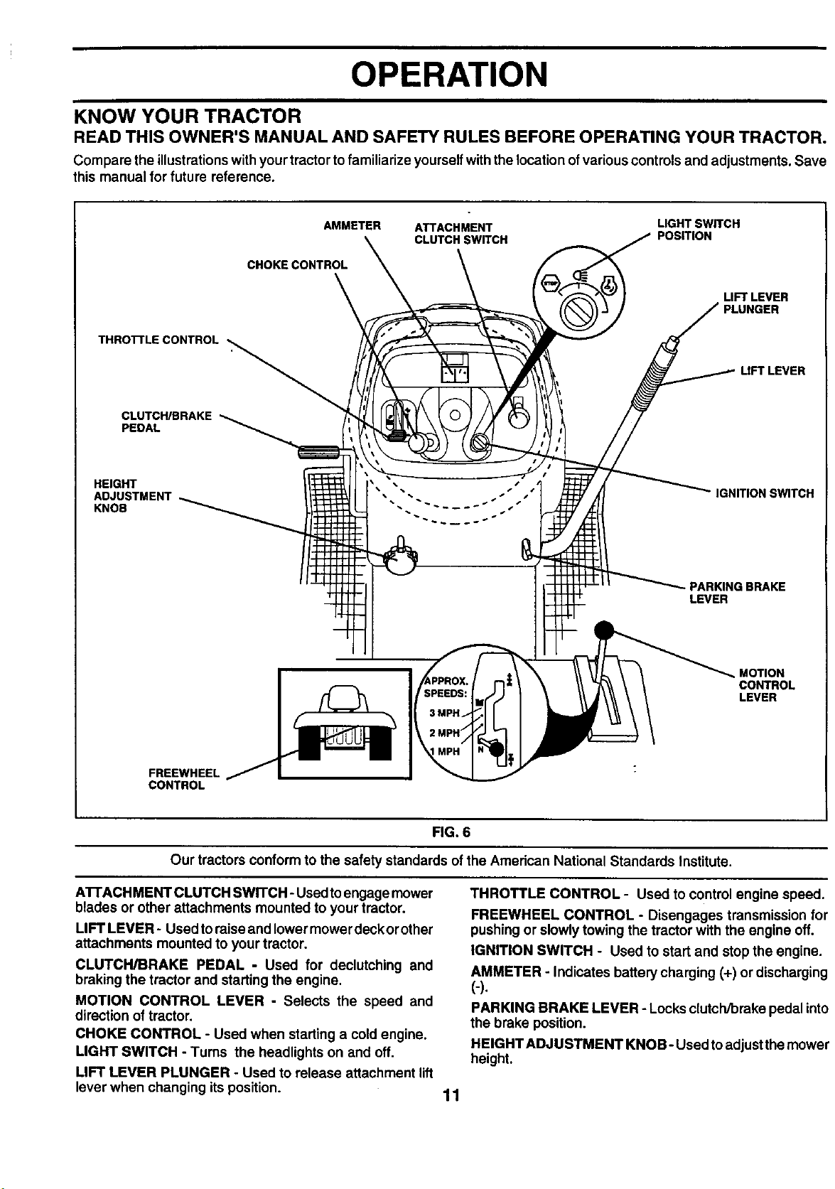
KNOW YOUR TRACTOR
READ THIS OWNER'S MANUAL AND SAFETY RULES BEFORE OPERATING YOUR TRACTOR.
Compare the illustrationswith your tractorto familiarize yourselfwith the location of variouscontrols and adjustments. Save
this manual for future reference.
THROI-I'LECONTROL
CLUTCH/BRAKE
PEDAL
HEIGHT
ADJUSTMENT
KNOB
AMMETER ATTACHMENT LIGHT SWITCH
CLUTCH SWITCH POSITION
CHOKE CONTROL
LIFT LEVER
PLUNGER
LIFT LEVER
IGNITION SWITCH
- PARKING BRAKE
LEVER
FREEWHEEL
CONTROL
Our tractors conform to the safety standards of the American National Standards Institute.
A'B'ACHMENT CLUTCH SWITCH -Used toengage mower
blades or other attachments mounted to your tractor.
LIFT LEVER - Used to raise and lower mower deck or other
attachments mounted to your tractor.
CLUTCH/BRAKE PEDAL - Used for declutching and
braking the tractor and starting the engine.
MOTION CONTROL LEVER - Selects the speed and
direction of tractor.
CHOKE CONTROL - Used when starting a cold engine.
LIGHT SWITCH - Turns the headlights on end off.
LIFT LEVER PLUNGER - Used to release attachment lift
lever when changing its position.
MOTION
CONTROL
LEVER
FIG. 6
THROTTLE CONTROL - Used to control engine speed.
FREEWHEEL CONTROL - Disengages transmission for
pushing or slowly towing the tractor with the engine off.
IGNITION SWITCH - Used to start and stop the engine.
AMMETER - Indicates battery charging (+) or discharging
(-).
PARKING BRAKE LEVER - Locks clutch/brake pedal into
the brake position.
HEIGHT ADJUSTMENT KNOB- Used toadjust the mower
height.
11
OPERATION
in severe eye damage. Always wear safety glasses or eye shields while operating your tractor
I The operation of any tractor can result in foreign objects thrown into the eyes, which can result I
or performing any adjustments or repairs. We recommend a wide vision safety mask over
spectacles or standard safety glasses.
I
HOW TO USE YOUR TRACTOR
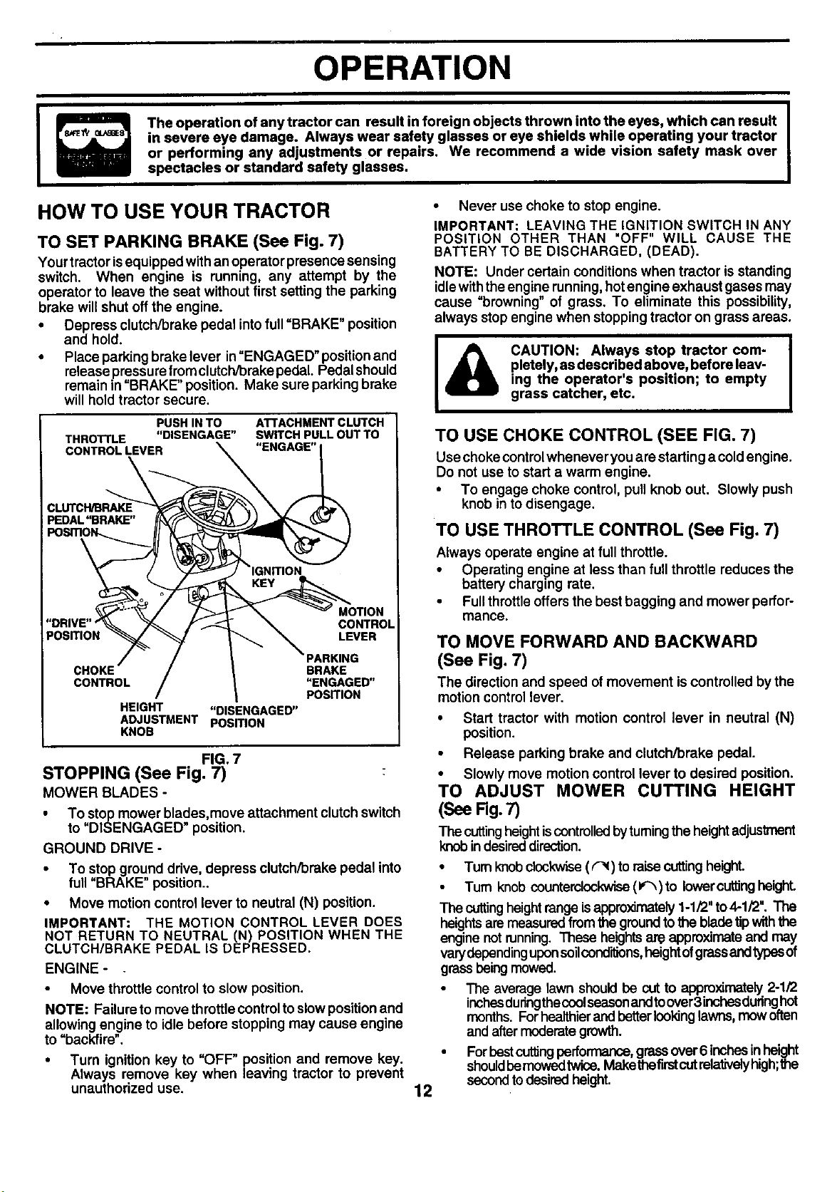
TO SET PARKING BRAKE (See Fig. 7)
Yourtractor isequipped with an operator presence sensing
switch. When engine is running, any attempt by the
operator to leave the seat without first setting the parking
brake will shut off the engine.
• Depress clutch/brake pedal intofull =BRAKE" position
and hold.
• Place parkingbrake lever in=ENGAGED" positionand
release pressurefromclutch/brake pedal. Pedal should
remain in =BRAKE" position. Make sure parking brake
will hold tractor secure,
PUSHINTO
THROTrLE "DISENGAGE"
CONTROLLEVER
ATTACHMENT CLUTCH
SWITCH PULL OUT TO
"ENGAGE"
\
PosmoN LEVER
CHOKE BRAKE
CONTROL "ENGAGED"
HEIGHT "DISENGAGED"
ADJUSTMENT POSITION
KNOB
FIG. 7
STOPPING (See Fig. 7)
MOWER BLADES -
• To stop mower blades,move attachment clutchswitch
to "DISENGAGED" position.
GROUND DRIVE -
• To stop ground drive, depress clutch/brake pedal into
full=BRAKE" position..
• Move motion control lever to neutral (N) position.
IMPORTANT: THE MOTION CONTROL LEVER DOES
NOT RETURN TO NEUTRAL (N) POSITION WHEN THE
CLUTCH/BRAKE PEDAL IS DEPRESSED.
ENGINE -
• Move throttle control to slow position.
NOTE: Failure to move throttle controlto slow positionand
allowing engine to idle before stopping may cause engine
to =backfire".
• Turn ignition key to =OFF" position and remove key.
Always remove key when leaving tractor to prevent
unauthorized use.
CONTROL
PosmoN
• Never use choketo stop engine.
IMPORTANT: LEAVING THE IGNITION SWITCH IN ANY
POSITION OTHER THAN "OFF" WILL CAUSE THE
BATTERY TO BE DISCHARGED, (DEAD).
NOTE: Under certain conditions when tractor is standing
idlewiththe engine running,hotengineexhaust gases may
cause =browning" of grass. To eliminate this possibility,
always stopengine when stopping tractor on grass areas.
CAUTION: Always stop tractor com- |
pletely, as described above, before leav-
&
TO USE CHOKE CONTROL (SEE FIG. 7)
Use chokecontrolwhenever you are starting a cold engine.
Do not use to start a warm engine.
• To engage choke control, pull knob out. Slowly push
knob in to disengage.
TO USE THROTTLE CONTROL (See Fig. 7)
Always operate engine at full throttle.
• Operating engine at lessthan fullthrottle reduces the
battery charging rate.
• Fullthrottle offersthe best bagging and mower perfor-
mance.
TO MOVE FORWARD AND BACKWARD
(See Fig. 7)
The direction and speed of movement iscontrolled bythe
motion control lever.
• Start tractor with motion control lever in neutral (N)
position.
• Release parking brake and clutch/brake pedal.
• Slowly move motion control lever to desired position.
TO ADJUST MOWER CUTTING HEIGHT
ing the operator's position; to empty
grass catcher, etc.
(See Rg. 7)
The cuttingheightiscontrolledbytumingthe heightadjustment
knobin desireddirection.
• Turnknobclockwise(r'_) to raisecuttingheight.
Turn knob counterclockwise(1_) to lower cuttingheight.
The cuttingheight range isappro)dmately1-1/2" to4-1/2". The
heights are measuredfrom the ground to the blade tipwith
engine not running. These heights are approximate and may
varydependingupon soil conditions,height of grass andtypesof
grass beingmowed.
• The average lawn shouldbe cutto approximately2-1/2
inchesduringthecoolseasonandtoover3inchesduringhot
months. Forhealthierand betterlookinglawns, mow often
and aftermoderategrowth.
• ForbestcutlJngperformance,grassover6 inchesin height
shouldbemowedtwice.Makethefirstcutrelativelyhigh;the
12
secondto desiredheight.
!
I
OPERATION
TO ADJUST GAUGE WHEELS (See Fig. 8)
Gauge wheels are properly adjusted when they are slightly
offthe ground when mower is at the desired cutting height
in operating position. Gauge wheels then keep the deck in
proper position to help prevent scalping in most terrain
conditions.
• Adjust gauge wheels withtractor ona flat level surface.
• Adjust mower to desired cutting height (See =TO AD-
JUST MOWER CUTTING HEIGHT"in the Operation
section of this manual).
• With mower in desired height of cut position, gauge
wheels should be assembled so they are slightlyoff the
ground. Install gauge wheel in appropdate hole with
shoulder bolt, 3/8 washer, and 3/8-16 Iocknut and
tighten securely.
• Repeat for opposite side installing gauge wheel in
same adjustment hole.
GAUGE
WHEEL
MOUNTING
3/8-16
LOCKNU1
SHOULDER
BOLT
FIG. 8
TO OPERATE MOWER (See Figs. 6 and 7)
Yourtractor isequipped withan operator presence sensing
switch. Any attempt by the operator to leave the seat with
the engine running and the attachment clutchengaged will
shut offthe engine.
• Select desired height of cut.
• Lower mower with attachment liftcontrol.
• Start mower blades by engaging attachment clutch
control.
• TO STOP MOWER BLADES -disengage attachment
clutchcontrol. :
• Choose the slowestspeed before starting up or down
hills.
• Avoid stopping or changing speed on hills.
• If slowing is necessary, move throttle control lever to
slower position.
• Ifstopping isabsolutely necessary, push clutch/brake
pedal quickly to brake position and engage parking
brake.
• Move motioncontrol lever to neutral (N) position.
IMPORTANT: THE MOTION CONTROL LEVER DOES
NOT RETURN TO NEUTRAL (N) POSITION WHEN THE
CLUTCH/BRAKE PEDAL IS DEPRESSED.
• To restartmovement, slowlyrelease parkingbrakeand
clutch/brake pedal.
• Slowly move motion control lever to slowest setting.
• Make all turns slowly.
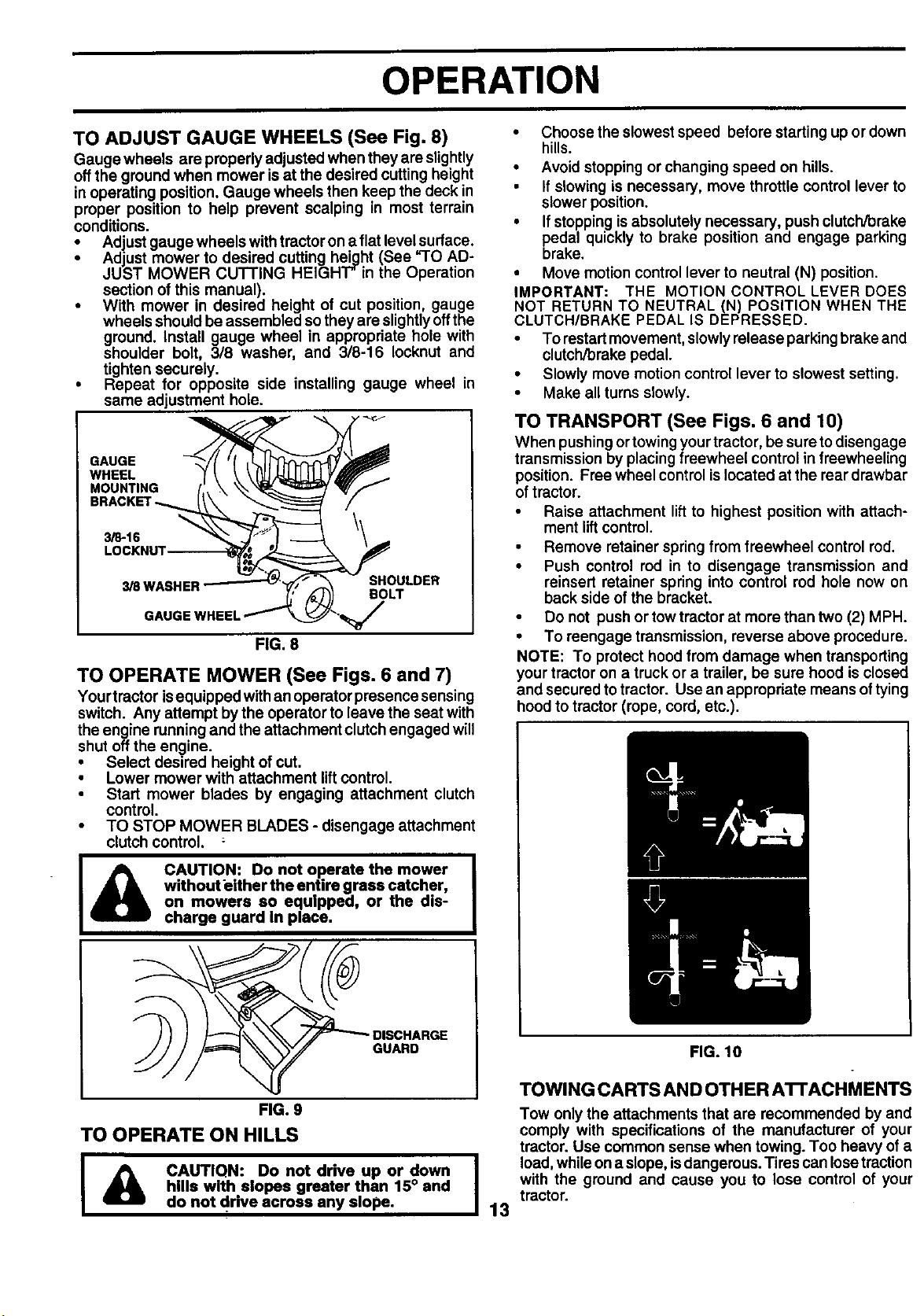
TO TRANSPORT (See Figs. 6 and 10)
When pushing ortowingyour tractor, be sure to disengage
transmission by placing freewheel control in freewheeling
position. Free wheel controlislocated at the roar drewbar
of tractor.
Raise attachment liftto highest position with attach-
ment lift control.
• Remove retainer spring from freewheel control rod.
• Push control rod in to disengage transmission and
reinsert retainer spring into control rod hole now on
back side of the bracket.
Do not push or tow tractorat more than two (2) MPH.
• To reengage transmission, reverse above procedure.
NOTE: To protect hood from damage when transporting
your tractor on a truckor a trailer, be sure hood is closed
and secured to tractor. Use an appropriate means oftying
hood to tractor (rope, cord, etc.).
CAUTION: Do not operate the mower
withouteither the entire grass catcher,
on mowers so equipped, or the dis-
charge guard in place.
GUARD
FIG. 9
TO OPERATE ON HILLS
I & CAUTIQN: Donotdriveupordown I
hills with elopes greater than 15° and
do not drive across any slope. 13
FIG. 10
TOWING CARTS AND OTHER ATrACHMENTS
Tow only the attachments that are recommended by and
comply with specifications of the manufacturer of your
tractor. Use common sense when towing. Too heavy of a
load,while ona slope, is dangerous. Tires can losetraction
with the ground and cause you to lose control of your
tractor.
OPERATION
BEFORE STARTING THE ENGINE
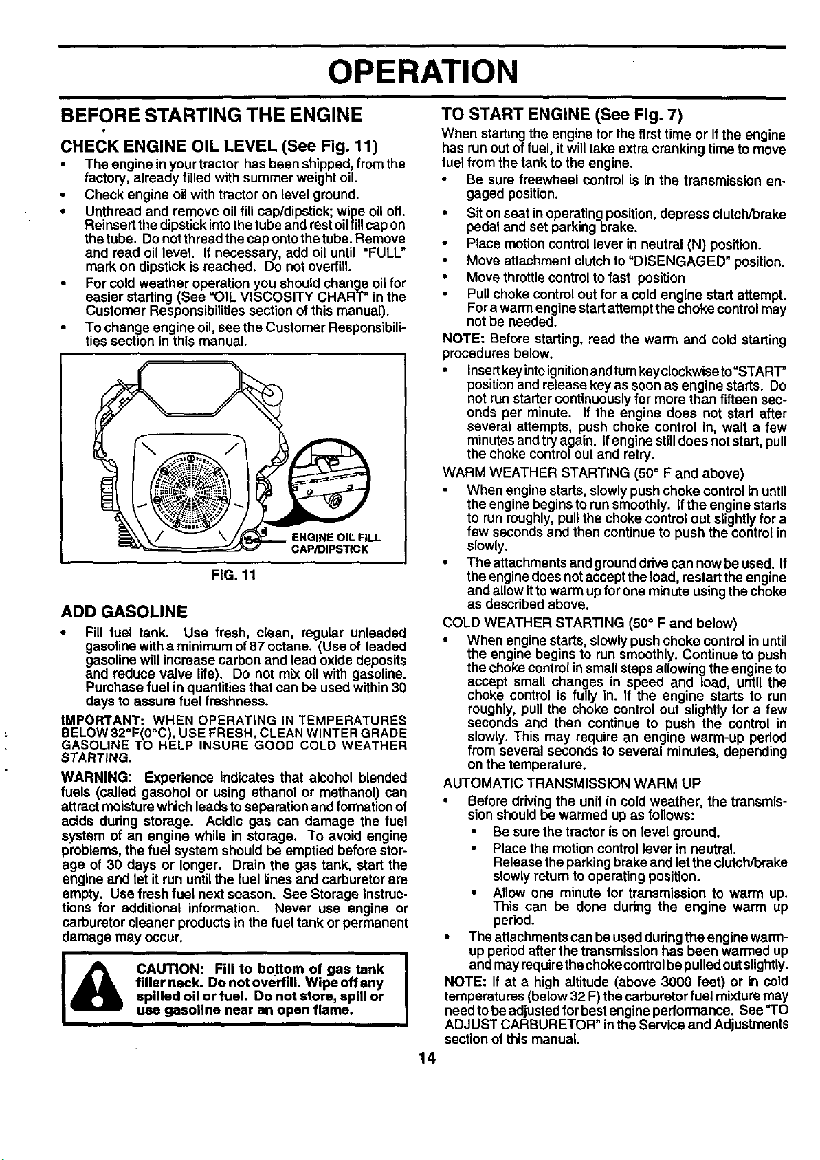
CHECK ENGINE OIL LEVEL (See Fig. 11)
• The engine in your tractor has been shipped, fromthe
factory, already filled with summer weight oil.
• Check engine oilwith tractor on level ground.
• Unthread and remove oil flUcap/dipstick; wipe oil off.
Reinsert the dipstick intothe tube end rest oilfill capon
the tube. Do notthread the cap ontothe tube. Remove
and read oil level. If necessary, add oil until "FULL"
mark on dipstick is reached. Do not overfill.
• For cold weather operation you should change oil for
easier starting (See "OIL VISCOSITY CHART" in the
Customer Responsibilities section of this manual).
• To change engine oil, see the Customer Responsibili-
ties section in this manual.
ENGINE OIL FILL
CAP/DIPSTICK
FIG. 11
ADD GASOLINE
• Fill fuel tank. Use fresh, clean, regular unleaded
gasoline with a minimum of 87 octane. (Use of leaded
gasoline will increase carbon and lead oxide deposits
and reduce valve life). Do not mix oil with gasoline.
Purchase fuel inquantities that can be used within 30
days to assure fuel freshness.
IMPORTANT: WHEN OPERATING IN TEMPERATURES
BELOW 32°F(0°C), USE FRESH, CLEAN WINTER GRADE
GASOLINE TO HELP INSURE GOOD COLD WEATHER
STARTING.
WARNING: Experience indicates that alcohol blended
fuels (called gasohol or using ethanol or methanol) can
attract moisture which leads toseparation and formation of
acids during storage. Acidic gas can damage the fuel
system of an engine while in storage. To avoid engine
problems, the fuel system should be emptied before stor-
age of 30 days or longer. Drain the gas tank, start the
engine and let it run until the fuel lines and carburetor are
empty. Use fresh fuel next season. See Storage Instruc-
tions for additional information. Never use engine or
carburetor cleaner products in the fuel tank or permanent
damage may occur.
filler neck. Do not overfill, Wipe off any
I& CAUTION: Fill to bottom of gas tank I
spilled oil or fuel. Do not store, spill or
use gasoline near an open flame.
TO START ENGINE (See Fig. 7)
When starting the engine for the first time or if the engine
has run out of fuel, itwilltake extra cranking time to move
fuel from the tank to the engine,
Be sure freewheel control is in the transmission en-
gaged position.
• Sit on seat in operating position, depress clutch/brake
pedal and set parking brake.
• Place motion control lever inneutral (N) position.
• Move attachment clutch to'DISENGAGED" position.
• Move throttlecontrol to fast position
• Pullchoke control out for a cold engine start attempt.
Fora warm engine startattemptthe choke controlmay
not be needed.
NOTE: Before starting, read the warm and cold starting
procedures below.
• Insertkeyintoignitionandturnkeyclockwise to=START,,
position and release key as soon asengine starts. Do
not run starter continuouslyfor more than fifteen sec-
onds per minute. If the engine does not start after
several attempts, push choke control in, wait a few
minutes and try again. If engine stilldoes notstart, pull
the choke controlout and retry.
WARM WEATHER STARTING (50° F and above)
• When engine starts, slowlypush choke control in until
the engine begins to runsmoothly. Ifthe engine starts
to run roughly, pullthe choke control out slightly for a
few seconds and then continue to push the control in
slowly.
• The attachments and grounddrive can now be used. If
the engine does notaccept the load, restart the engine
and allow ittowarm up forone minute usingthe choke
as described above.
COLD WEATHER STARTING (50° F and below)
• When engine starts, slowlypush choke control in until
the engine begins to run smoothly. Continue to push
the choke control in small steps allowing the engine to
accept small changes in speed and load, until the
choke control is fully in. If the engine starts to run
roughly, pull the choke control out slightly for a few
seconds and then continue to push the control in
slowly. This may require an engine warm-up period
from several seconds to several minutes, depending
on the temperature.
AUTOMATIC TRANSMISSION WARM UP
• Before driving the unit in cold weather, the transmis-
sion should be warmed up as follows:
• Be sure the tractor is on level ground.
• Place the motion control lever in neutral.
Release the parkingbrake and let the clutch/brake
slowly return to operating position.
• Allow one minute for transmission to warm up.
This can be done dudng the engine warm up
period.
• The attachments can be usedduring the engine warm-
i
I
up pedod after the transmission has been warmed up
and may requirethe choke controlbe pulledout slightly.
NOTE: If at a high altitude (above 3000 feet) or in cold
temperatures (below 32 F) the carburetor fuel mixture may
need tobe adjustedfor bestengine performance. See "TO
ADJUST CARBURETOR" inthe Service and Adjustments
section of this manual.
14
OPERATION
PURGE TRANSMISSION •
CAUTION: Never engage or disengage [
AI freewheel lever while the engine is run- I
I ning. I
To ensure proper operation and performance, it is recom-
mended that the transmission be purged before operating
tractor for the first time. This procedure will remove any
trapped air inside the transmission which may have devel-
oped during shipping of your tractor.
IMPORTANT: SHOULDYOURTRANSMISSION REQUIRE
REMOVAL FOR SERVICE OR REPLACEMENT, IT
SHOULD BE PURGED AFTER REINSTALLATION
BEFORE OPERATING THE TRACTOR.
• Place tractorsafely onlevelsurface withengine offand
parking brake set.
Disengage transmission by placing freewheel control
in freewheeling position (See "TO TRANSPORT" in
this section of manual).
Sitting inthe tractor seat, start engine. After the engine
isrunning, move throttle controlto slow position. With
motion control lever in neutral (N) position, slowly
disengage clutch/brake pedal.
• Move motion control lever to full forward position and
hold for five (5) seconds. Move lever to full reverse
position and hold for five (5) seconds. Repeat this
procedure three (3) times.
NOTE: Duringthis procedure there willbeno movement of
drivewheels. The air is being removed fromhydraulicdrive
system.
• Move motioncontrolleverto neutral (N) position. Shut-
off engine and set parking brake.
• Engage transmission by placing freewheel control in
drivingposition(See "TO TRANSPORT" inthis section
of manual).
• Sittinginthe tractor seat, startengine. Afterthe engine
is running, move throttle control to half (1/2) speed.
With motion control lever in neutral (N) position, slowly
disengage clutch/brake pedal.
• Slowly move motion control lever forward, after the
tractor moves approximately five (5)feet, slowly move
motion control lever to reverse position. After the
tractor moves approximately five(5) feet return the
motioncontrollever to the neutral (N) position. Repeat
this procedure with the motion control lever three (3)
times.
• Your tractor is now purged and now ready for normal
operation.
MOWING TIPS
• Tire chains cannot be used when the mower housingis
attached to tractor.
• Mower should be properly leveled for best mowing
performance. See "TO LEVEL MOWER HOUSING" in
the Service and Adjustments section ofthis manual.
• The left hand side of mower should be used for trim-
ming.
• Drive so that clippings are discharged onto the area
that has been cut. Have the cut area to the rightof the
tractor. This will result in a more even distribution of
clippingsand more uniform cutting.
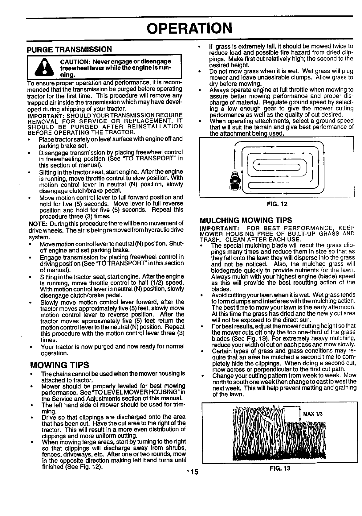
• When mowinp large areas, start by turning to the right
so that clippings will discharge away from shrubs,
fences driveways, etc. After one or two rounds, mow
in the opposite direction making left hand tums unt
finished (See Fig. 12).
:15
If grass is extremely tall, it should be mowed twice to
reduce load and possible fire hazard from dried clip-
pings. Make first cut relatively high;the second tothe
desired height.
Do not mow grass when it iswet. Wet grass will plug
mower and leave undesirable clumps. Allow grass to
dry before mowing.
Always operate eng.ineat full throttle when mowing to
assure better mowing performance and proper dis-
charge of material. Regulate ground speed by select-
ing a low enough gear to give the mower cutting
_ehrformance as well as the quality of cut desired.
en operating attachments, select a ground speed
that will suitthe terrain and give best performance of
the attachment bein 9 used.
FIG. 12
MULCHING MOWING TIPS
IMPORTANT: FOR BEST PERFORMANCE, KEEP
MOWER HOUSING FREE OF BUILT-UP GRASS AND
TRASH. CLEAN AFTER EACH USE.
• The special mulching blade will recut the grass clip-
pings many times and reduce them in size so that as
they fall onto the lawn they will disperse intothe grass
and not be noticed. Also, the mulched grass will
biodegrade quickly to provide nutrients for the lawn.
Always mulch with your highest engine (blade) speed
as this will provide the best recutting action of the
blades.
• Avoidcuttingyour lawn when itiswet. Wet grass tends
toform clumps and interferes with the mulchingaction.
The best time to mow your lawn isthe early afternoon.
Atthis time the grass has driedand the newly cut area
will not be exposed to the direct sun.
• For bestresults, adjust the mowercuttingheight so that
the mower cuts off only the top one-third of the grass
blades (See Fig. 13). For extremely heavy muIching,
reduceyour widthof cuton each pass and mow slowly.
• Certain types of grass and grass conditions may re-
quire that an area be mulched a second time to com-
pletely hide the clippings. When doing a second cut,
mow across or perpendicular to the first cut path.
• Change your cutting pattern from week to week. Mow
northtosouth one weekthen change toeast to west the
nextweek. This will help prevent matting and graining
of the lawn.
FIG. 13
CUSTOMER RESPONSIBILITIES
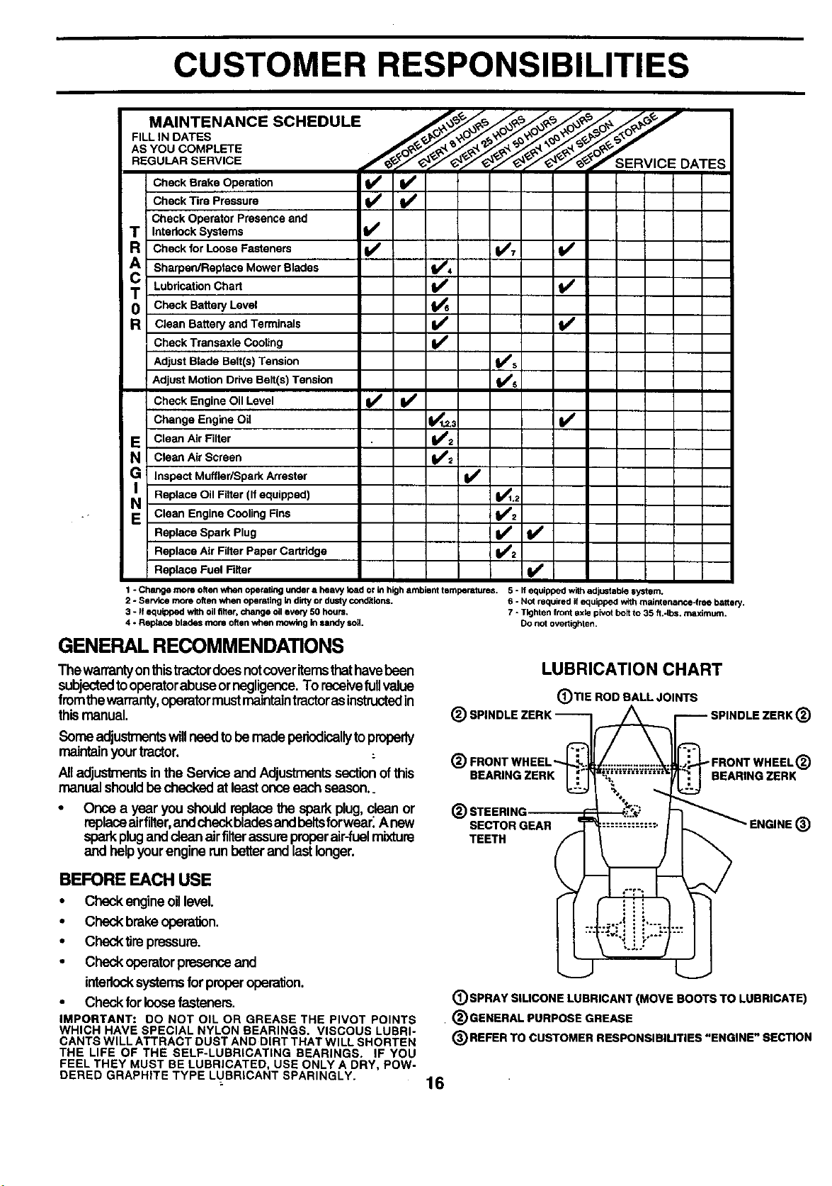
MAINTENANCE SCHEDULE ,*_ _ _. ,_,_ ,_'_ c,_
AS YOU COMPLETE ,_.'_ _,'_._,'_._O_-_
REGULARSERVICE _'/_/¢_'/_/¢t_//_-//_"_/T/_'-_**'S ERVICE
cC:::: BTir:; rOsP:ur_:'°n _
Check Operator Presence and
T Intedock Systems
R Check for Loose Fasteners I_ 1_7
A SharperdReplece Mower Blades II,/'=
0 Check Battery Level
ic Lu.deat,onC.a. ,/
R Clean Battery and Terminals
Check Transaxle Cocting
Adjust Blade Belt(s) Tension tfs
Adjust Motion Drive Belt(s) Tension k/s
Check Engine Oil Level if V'
I Change Engine Oil _,2.3 If
E Clean Air Filter VP2
N Clean Air Screen V'2
DATES
Inspect Muffler/Spark Arrester If
N Replace Oil Filter (If equipped) 11_1,;
Clean Engine Cooling Fins 11_'2
Replace Spark Plug _2 I#1
Replace Air Filter Paper Cadddge
Replace Fuel Filter ¥1
1 -Chartgemomoftenwhenoperafingunderaheavytoadorinhighambienttemperatures. 5-1fequippedwfihadjustablesyotem.
2 - Service more often when operatingin dirtyor dustycor_ifions. 6 -Not required if equipped withmaintenance-free battery.
3 - If equipped withoilfilter, change oil every50 hours. 7 - Tighten front Bxle pk_otholt to 35 fi.-Ibs, maximum.
4 - Reptace blades mote oftenwhen mowing Insandy soil. Do not overtighlen.
GENERAL RECOMMENDATIONS
The warranty onthistractordoes notcover itemsthathavebeen
subjectedto operatorabuse ornegligence. To receivefullvalue
fromthe warranty,operatormust maintaintractor asinstructedin
this manual.
Some adjustmentswillneed tobe madeperiodicallytoproperly
maintainyourtractor.
Alladjustmentsinthe Serviceand Adjustmentssectionofthis
manualshouldbechecked at leastonce eachseason..
Once a year you shouldreplacethe sparkplug, clean or
replaceairfilter,andcheckbladesandbeltsforwear_Anew
sparkplug anddean airfilterassureproperair-fuelmixture
and helpyour enginerunbetterand lastlonger.
BEFORE EACH USE
• Checkengineoillevel.
• Check brakeoperation.
• Checktire pressure.
• Checkoperatorpresenceand
interlocksystemsfor properoperation.
• Checkfor loosefasteners.
IMPORTANT: DO NOT OIL OR GREASE THE PIVOT POINTS
WHICH HAVE SPECIAL NYLON BEARINGS. VISCOUS LUBRI-
CANTS WILL ATTRACT DUST AND DIRT THAT WILL SHORTEN
THE LIFE OF THE SELF-LUBRICATING BEARINGS. IF YOU
FEEL THEY MUST BE LUBRICATED, USE ONLY A DRY, POW-
DERED GRAPHITE TYPE LUBRICANT SPARINGLY.
LUBRICATION CHART
(_)TIE ROD BALL JOINTS
_) SPINDLE ZEI (_
@ ®
BEARING ZERK BEARING ZERK
® STEERING
SECTOR GEAR "ENGINE ®
TEETH
(_)SPRAY SILICONE LUBRICANT (MOVE BOOTS TO LUBRICATE)
• (_GENERAL PURPOSE GREASE
(_REFER TO CUSTOMER RESPONSIBILITIES "ENGINE" SECTION
16
CUSTOMER RESPONSIBILITIES
TRACTOR
Always observe safety rules when performing any mainte-
nance.
BRAKE OPERATION
Iftractor requires more than six (6) feet stopping distance
at highspeed in highest gear, then brake must beadjusted.
(See "TO ADJUST BRAKE" in the Service and Adjust-
ments section of this manual).
TIRES
• Maintain proper air pressure in all tires (See =PROD-
UCT SPECIFICATIONS" section of this manual).
• Keeptires free of gasoline, oil,or insectcontrol chemi-
cals which can harm rubber.
• Avoid stumps, stones, deep ruts, sharp objects and
other hazards that may cause tire damage.
NOTE: To seal tire punctures and prevent flat tires due to
slow leaks, tire sealant may be purchased from your local
parts dealer. Tire sealant also prevents tire dry rot and
corrosion.
OPERATOR PRESENCE SYSTEM
Be sure operator presence and interlock systems are
working properly. If your tractor does not function as
described, repair the problem immediately.
• The engine should not start unless the clutch/brake
pedal isfully depressed and attachement clutchcontrol
is in the disengaged position.
• When the engine is running, any attempt bythe opera-
tor to leave the seat without first setting the parking
brake should shut off the engine.
• When the engine is runningand the attachment clutch
is engaged, any attempt by the operator to leave the
seat should shut off the engine.
• The attachment clutch shouldnever operete unlessthe
operator is inthe seat.
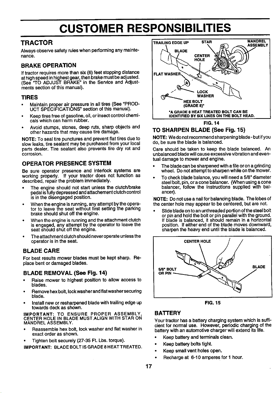
TRAILING EDGE UP STAR MANDREL
BLADE
HOLE
FLAT WASHEI_
i LOCK
WASHER
HEX BOLT
(GRADE 8)*
*A GRADE 8 HEAT TREATED BOLT CAN BE
IDENTIFIEDBY SIX LINES ON THE BOLT HEAD.
FIG. 14
TO SHARPEN BLADE (See Fig. 15)
NOTE: We donot recommend sharpening blade- butifyou
do, be sure the blade is balanced.
Care should be taken to keep the blade balanced. An
unbalanced blade willcause excessive vibrationand even-
tual damage to mower and engine.
• The blade can be sharpened with a file or on a gdnding
wheel. Do not attempt to sharpen while on the mower.
• To check blade balance, you will need a 5/8" diameter
steelbolt, pin, oracone balancer. (When usingacone
balancer, follow the instructions supplied with bal-
ancer).
NOTE: Do notuse a nail for balancing blade. The lobes of
the center hole may appear to be centered, but are not.
• Slide bladeon to an unthreaded portionofthe steelbolt
or pinand hold the boltor pin parallel with the ground.
If blade is balanced, it should remain in a horizontal
position. If either end of the blade moves downward,
sharpen the heavy end until the blade is balanced.
ASSEMBLY
BLADE CARE
For best results mower blades must be kept sharp. Re-
place bent or damaged blades.
BLADE REMOVAL (See Fig. 14)
• Raise mower to highest position to allow access to
blades.
• Remove hex bolt,lockwasher and flatwasher securing
blade.
• Install new or resharpened blade with trailing edge up
towards deck as shown.
IMPORTANT: TO ENSURE PROPER ASSEMBLY,
CENTER HOLE IN BLADE MUST.ALIGN WITH STAR ON
MANDREL ASSEMBLY.
• Reassemble hex bolt, lock washer and flat washer in
exact order as shown.
• Tighten bolt securely (27-35 Ft. Lbs. torque).
IMPORTANT: BLADE BOLT ISGRADE 8 HEAT TREATED.
FIG. 15
BATrERY
Your tractor has a battery charging system which is suffi-
cient for normal use. However, periodic charging of the
battery with an automotive charger will extend its life.
• Keep battery and terminals clean.
• Keep battery bolts tight.
Keep small vent holes open.
Recharge at 6-10 ampere s for I hour.
17
CUSTOMER RESPONSIBILITIES
NOTE: The original equipment battery on your tractor is
maintenance free. Do not attempt toopen or remove caps
or covers. Adding or checking level of electrolyte is not
necessary.
TO CLEAN BATI'ERY AND TERMINALS
Corrosion and dirt on the battery and terminals can cause
the battery to "leak" power.
• Remove terminal guard.
• Disconnect BLACK battery cable first then RED bat-
tery cable and remove battery from tractor.
• Rinse the battery with plain water and dry.
TRANSAXLE COOLING
The fan and cooling fins of transmission should be kept
clean to assure proper cooling.
Do notattempt to clean fan or transmission while engine is
running or while the transmission is hot. To prevent
possibledamage to seals, no not use high pressure water
or steam to clean transaxle.
• Inspect coolingfan to be surefan blades are intactand
clean.
• Inspect cooling fins for dirt, grass clippings and other
materials. To prevent damage to seals, do not usa
compressed air or high pressure sprayer to clean
cooling fins.
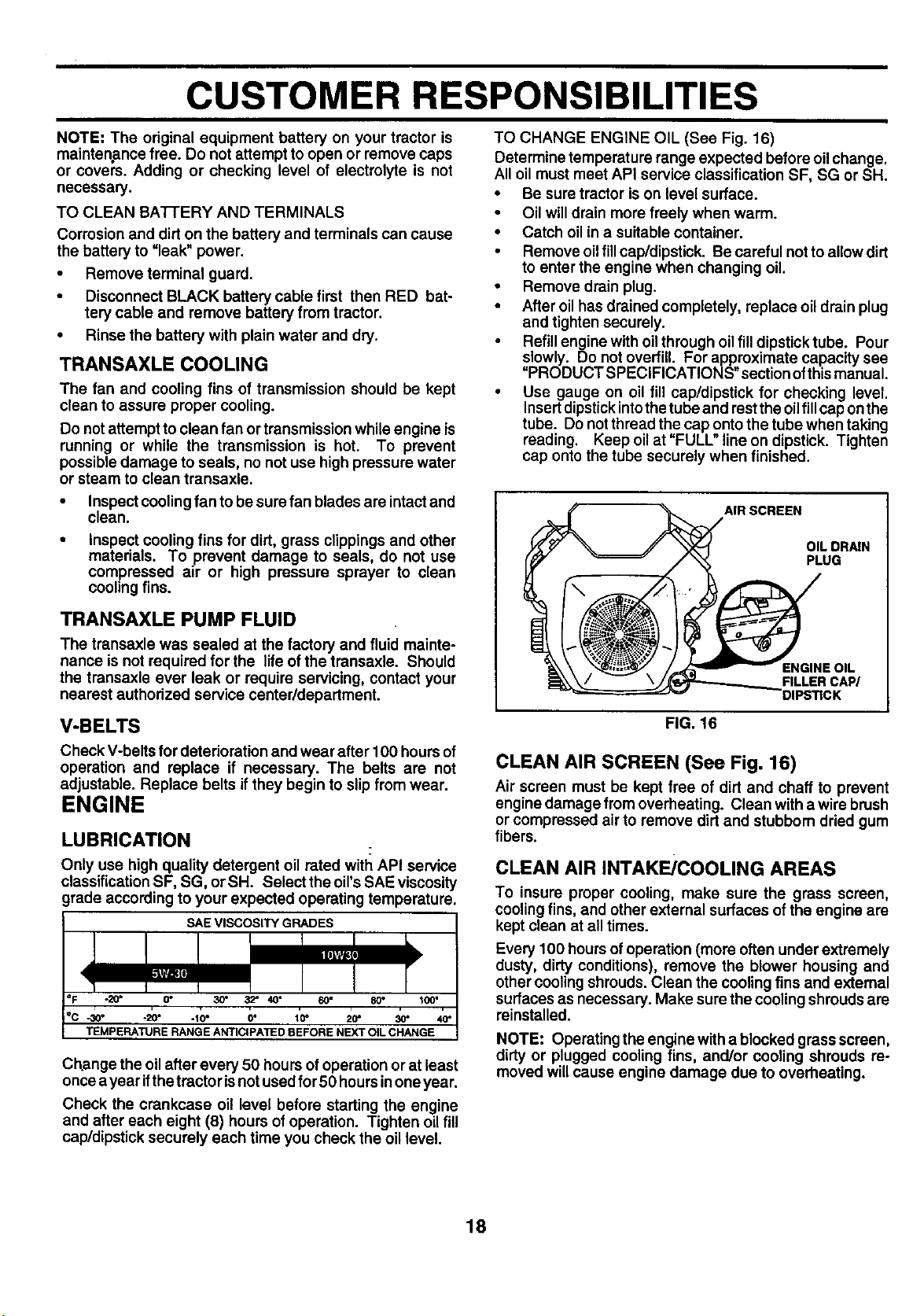
TO CHANGE ENGINE OIL (See Fig. 16)
Determine temperature range expected before oil change.
All oil must meet API service classification SF, SG or SH.
• Be sure tractor is on level surface.
• Oil will drain more freely when warm.
• Catch oil in a suitable container.
• Remove oil fill cap/dipstick. Be careful not to allow dirt
to enter the engine when changing oil.
• Remove drain plug.
• After oil has drained completely, replace oil drain plug
and tighten securely.
Refill engine with oil through oil fill dipstick tube. Pour
slowly. Do not overfill. For approximate capacity see
"PRODUCT SPECIFICATIONS" section ofthis manual.
• Use gauge on oil fill cap/dipstick for checking level.
Insert dipstick into the tube and rest the oil fill cap on the
tube. Do not thread the cap onto the tube when taking
reading. Keep oil at "FULL" line on dipstick. Tighten
cap onto the tube securely when finished.
AIR SCREEN
OIL DRAIN
PLUG
TRANSAXLE PUMP FLUID
The transaxle was sealed at the factory and fluid mainte-
nance is notrequired for the life of the transaxle. Should
the transaxle ever leak or require servicing, contact your
nearest authorized service center/department.
V-BELTS
Check V-belts for deterioration and wear after 100 hoursof
operation and replace if necessary. The belts are not
adjustable. Replace belts if they begin to slip from wear.
ENGINE
LUBRICATION
Only use high quality detergent oil rated with API service
classification SF, SG, or SH. Select the oirs SAE viscosity
grade according to your expected operating temperature.
SAE VISCOSITY GRADES
-20"
-30" -20" *10" 0_ 10" 20" 30'
TEMPERATURE RANGE ANTICIPATED BEFORE NEXT OIL CHANGE
Change the oil after every 50 hours of operationor at least
once ayear ifthetractor is not usedfor 50 hours inone year.
Check the crankcase oil level before starting the engine
and after each eight (8) hours of operation. Tighten oil fill
cap/dipstick securely each time you check the oil level.
ENGINE OIL
FILLER CAP/
FIG. 16
CLEAN AIR SCREEN (See Fig. 16)
Air screen must be kept free of dirt and chaff to prevent
engine damage from overheating. Clean with a wire brush
or compressed air to remove dirt and stubborn dried gum
fibers.
CLEAN AIR INTAKE/COOLING AREAS
To insure proper cooling, make sure the grass screen,
coolingfins, and other external surfaces of the engine are
kept clean at all times.
Every 100 hours of operation (more often underextremely
dusty, dirty conditions), remove the blower housing and
other cooling shrouds. Clean the cooling fins and external
surfaces as necessary. Make sure the cooling shroudsare
reinstalled.
NOTE: Operating the engine with a blocked grass screen,
dirty or plugged cooling fins, and/or cooling shrouds ra-
moved willcause engine damage due to overheating.
18
 Loading...