

Craftsman 944.609760 Owner's Manual
SF.ARS
OWNER'S
MANUAL
MODEL NO,
944.609760
Caution:
Read and follow
all Safety Rules
and Instructions
Before Operating
This Equipment
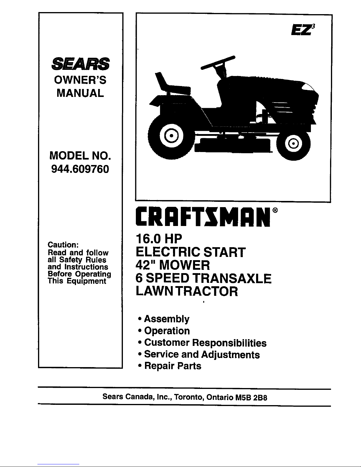
£RAFTSMAN°
16.0 HP
ELECTRIC START
42" MOWER
6 SPEED TRANSAXLE
LAWN TRACTOR
• Assembly
• Operation
• Customer Responsibilities
• Service and Adjustments
• Repair Parts
£Z 3
Sears Canada, Inc., Toronto, Ontario M5B 2B8
SAFETY RULES
, Safe Operation Practices for Ride-On Mowers
IMPORTANT: THIS CU'I-I'ING MACHINE IS cAPABLE OF AMPUTATING HANDS AND FEET AND THROWING
OBJECTS. FAILURE TO OBSERVE THE FOLLOWING SAFETY INSTRUCTIONS COULD RESULT IN SERIOUS
INJURY OR DEATH.
I. GENERAL OPERATION
• Read, understand, and follow all instructionsin the manual
and on the machine before starting.
Only allow responsible adults, who are familiar with the
instructions,to operate the machine.
Clear the area of ob ects such as rocks, toys, wire, etc,,
which could be p cked up and thrown by the bade.
Be surethe area isclear of other peoplebefore mowing.Stop
machine ifanyone enters the area.
• Never carry passengers.
Do not mow in reverse unless absolutely necessary. Always
lookdown and behind before and while backing.
Be aware ofthe mower discharge directionand do not point
it at anyone. Do n_,,operate the mower wi_houLeither the
entire grass catcher or the guard inplace.
Slow down before turning.
Never leave a runningmachine unattended. Always turn off
blades, set parking brake, stop engine, and remove keys
before dismounting.
Turn off blades when not mowing.
Stop engine before removing grass catcher or unclogging
chute.
Mow only indaylight orgood artificial light.
Do not operate the machine while under the influence of
alcoholor drugs.
Watch fortraffic when operating near orcrossingroadways.
• Use extra care when loadingor unloading the machine into
a trailer or truck.
II. SLOPE OPERATION
Slopes are ama or factor related to loss-of-control and tipover
accidents, which can result in severe inury or death. All slopes
requ re extra caut on. fyou cannot back upthe slope orifyou feet
uneasy on it, do not mow it.
DO:
Mow up and down slopes, not across.
Remove obstacles such as rocks, tree limbs, etc.
Watch for holes, ruts, or bumps. Uneven terrain could
overtum the machine. Tall grass can hide obstacles.
• Use slow speed. Choose a low gear so thatyou willnot have
to stop or shift while on the slope.
Follow the manufacturer's recommendations for wheel
weights or counterweights to improve stability.
Use extra care with grass catchers or other attachments.
These can change the stability of the machine.
Keep all movement on the slopes slowand gradual. Do not
make sudden changes inspeed or direction.
Avoid starting or stopping on a slope. If tires lose traction,
disengage the blades and proceed slowly straightdownthe
slope.
" -Do NOTi
Donot turnonslopes unless necessary, andthen, turnslowly
and gradually downhill, if possible.
Do notmow near drop-offs, ditches, orembankments. The
mower could suddenly turn over if a wheel is over the edge
ofa cliffor ditch, or if an edge caves in.
Do not mow on wet grass. Reduced traction could cause
sliding.
Do not tryto stabilizethe machine byputtingyour feet onthe
ground.
IlL CHILDREN
Tragic accidents can occur if the operator is not alert to the
presence ofchildren. Children are oftenattracted tothe machine
and the mowingactivity. Neverassume that children willremain
where you last saw them.
Keep childrenout ofthe mowing area and under the watchful
care of another responsible adult.
Be alert and turn machine off if children enter the area.
• Before and when backing, look behind and down for small
children.
Never carry children. They may fall off and be seriously
injured or interfere with safe machine operation,
Never allow children to operate the machine.
Use extra care when approaching blind comers, shrubs,
trees, or other objects that may obscure vision.
IV. SERVICE
Use extra care inhandlinggasoline and other fuels. They are
flammable and vapors are explosive,
Use only an approved container.
Never remove gas cap or add fuel with the engine
running. Allow engine to cool before refueling. Do not
smoke.
Never refuel themachine indoors.
Never store the machine or fuel container inside where
there is an open flame, such as a water heater.
Never run a machine inside a closed area.
• Keep nutsand bolts,especially blade attachment bolts,tight
and keep equipment in good condition.
Never tamper with safety devices. Check their proper
operation regularly.
Keep machine free of grass, leaves, orother debds build-up.
Clean oil or fuel spillage. Allow machine to cool before
stodng.
Stop and inspect the equipment if you strike an object.
Repair, if necessary, before restarting.
• Never make adjustments or repairswith the engine running.
Grass catcher componentsare sub ect to wear, damage, and
detedoration, which cou d expose mov ng pads or aow
objects to be thrown. Frequently check components and
replace withmanufacturer'srecommended parts, when nec-
essary.
Mewer blades are sharp and can cut. Wrap the blade(s) or
wear gloves, and use extra caution when servicing them.
Check brake operation frequently. Adjust and service as
required.
Look for this symbol to point out impor- I
tant safety precautions. It means
CAUTION!!I BECOMEALERTIH YOUR
SAFETY IS INVOLVED.
CAUTION: Always disconnect spark
plug wire and place wire where it cannot
contact spark plug in order to prevent
accidental starting when setting up,
transporting, adjusting or making
repairs.
Do not use grass catcher on steep slopes.
CONGRATULATIONS on your purchase of a Sears
Tractor. It has been designed, engineered and manufac-
tured to give you the best possible dependability and
_ performance. _ . " . .
Should you expedence any problem you cannot easily
remedy, please contact your nearest Sears Authorized
Service CentedDepartment. We have competent, well-
trained technicians and the proper tools toservice or repair
this tractor.
Please read and retain this manual. The instructions will
enable you to assemble and maintain your tractor properly.
Always observe the "SAFETY RULES".
MODEL
NUMBER 944.609760
SERIAL
NUMBER
DATEOF PURCHASE
THE MODEL AND SERIAL NUMBERS WILL BE FOUND
ON A PLATE UNDER THE SEAT.
YOU _OULD RECORD BOTH SERIAL NUMBER AND
DATE OF PURCHASE AND KEEP IN A SAFE PLACE
FOR FUTURE REFERENCE.
MAINTENANCE AGREEMENT
A Sears Maintenance Agreement is available onthisprod-
uct. Contact your nearest Sears store for details.
CUSTOMER RESPONSIBILITIES
Readandobservethesafetyrules.
Fellowaregularscheduleinmaintaining,caringforandusing
yourtractor.
• FoTIowthe instructionsunder"Customer Responsibilities"
and=Storage"sectionsofthisowner'smanual.
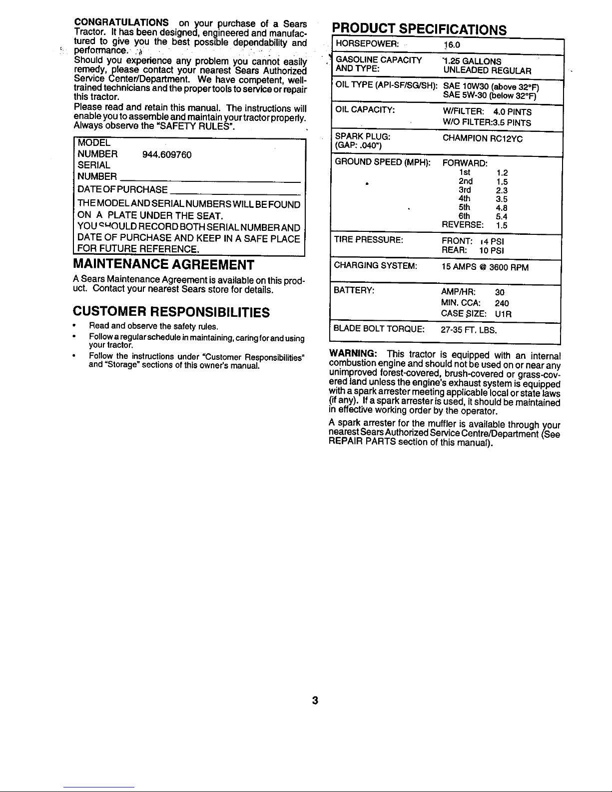
PRODUCT SPECIFICATIONS
HORSEPOWER: 16.0
GASOLINECAPACITY 1.25 GALLONS
ANDTYPE: UNLEADEDREGULAR
OIL TYPE (API-SF/SG/SH): SAE 10W30 (above 32°F)
SAE 5W-30 (below 32°F)
OIL CAPACITY: W/FILTER: 4.0 PINTS
W/O FILTER:3.5 PINTS
SPARK PLUG: CHAMPION RC12YC
GAP: .040")
GROUND SPEED (MPH): FORWARD:
1st 1.2
2rid 1.5
3rd 2.3
4th 3.5
5th 4.8
6th 5.4
REVERSE: 1.5
TIRE PRESSURE: FRONT: 14PSI
REAR: 10PSi
CHARGING SYSTEM: 15 AMPS @3600 RPM
BATTERY: AMPiHR: 30
MIN. CCA: 240
CASE _SIZE: U1R
i
BLADE BOLT TORQUE: 27-35 FT. LBS.
WARNING: This tractor Is equipped with an internal
combustionengine and shouldnotbe used onor near any
unimprovedforest-covered, brush-coveredor grass-cov-
ered land unlessthe engine's exhaust system is equipped
with a sparkarrester meetingapplicable localor state laws
(ifany). Ifa spark arrester isused,it shouldbe maintained
in effectiveworking order by the operator.
A spark arrester for the muffler is available throughyour
nearestSearsAuthorizedService Centre/Department (See
REPAIR PARTS section of this manual).
3
TABLE OF CONTENTS
SAFETY RULES ............................................................ 2
• PRODUCT SPECIFICATIONS .......... :..._,....... ,...:...._#J_'.3
CUSTOMER RESPONSIBILITIES ..................... 3, 14-17
WARRANTY .................................................................. 4
ASSEMBLY ................................................................ 6-8
OPERATION ........................................ ..................... 9-13
MAINTENANCE SCHEDULE ...................................... 14
SERVICE AND ADJUSTMENTS ............................ 18-23
STORAGE ...................... ............................................. 24
TROUBLESHOOTING ............................................ 25-26
REPAIR PARTS - TRACTOR ................................. 28-43
REPAIR PARTS - ENGINE .................................... 44-53
PARTS ORDERING/SERVICE ................ BACK COVER
LIMITED TWO (2) YEAR WARRANTY ON CRAFTSMAN TRACTOR (RIDING EQUIPMENT)
For two (2) years from date of purchase Sears Canada, Inc. will repair or replace at Sears optionfree of charge parts which are
defective as a result ofmaterial orworkmanship.
FULL ONE (1) YEAR WARRANTY GN BA'I-rERY
For one (1) year from date of purchase, if any battery included with this riding equipment proves defective in materiel or
workmanship and our testing determines the batterywill nothold a charge, Sears will replac,ethe battery at no charge.
COMMERCIAL OR RENTAL USE
Warranty on Riding Equipment used for commemiel or rental purposesis limitedton!nety (90) days.
This Warranty does NOT cover:
1. Pre-dellvery set-up.
2. Tire replacement or repair caused by punctures from outside objects (such as nails, thorns, stumps, or glass).
3. Expendable items which become worn dudng normal use, such as blades, spark plug, air cleaners and belts.
4. Repairs necessary because of operator abuse or negligence, Including damaged jaoksheft or mandrel end the
failure to operate and maintain the equipment according to the Instructions contained In the Owner's Manual.
5. In Home service.
Warranty service is available by returningthe Craftsman Riding Equipmentto the nearest Sears Service Centre/Department in
Canada. This warranty applies onlywhile this productis inuse inCanada.
This warranty is in addition to any statutory warranty and does not exclude or limit legal rights you may have but shall run
concurrentlywith applicable provinciallegislation. Furthermore, some provinces do NOT ellow limitationon how long an implied
warranty will lastso the above limitationsmay not apply to you.
SEARS CANADA, INC., TORONTO, ONTARIO M5B 2B8
4
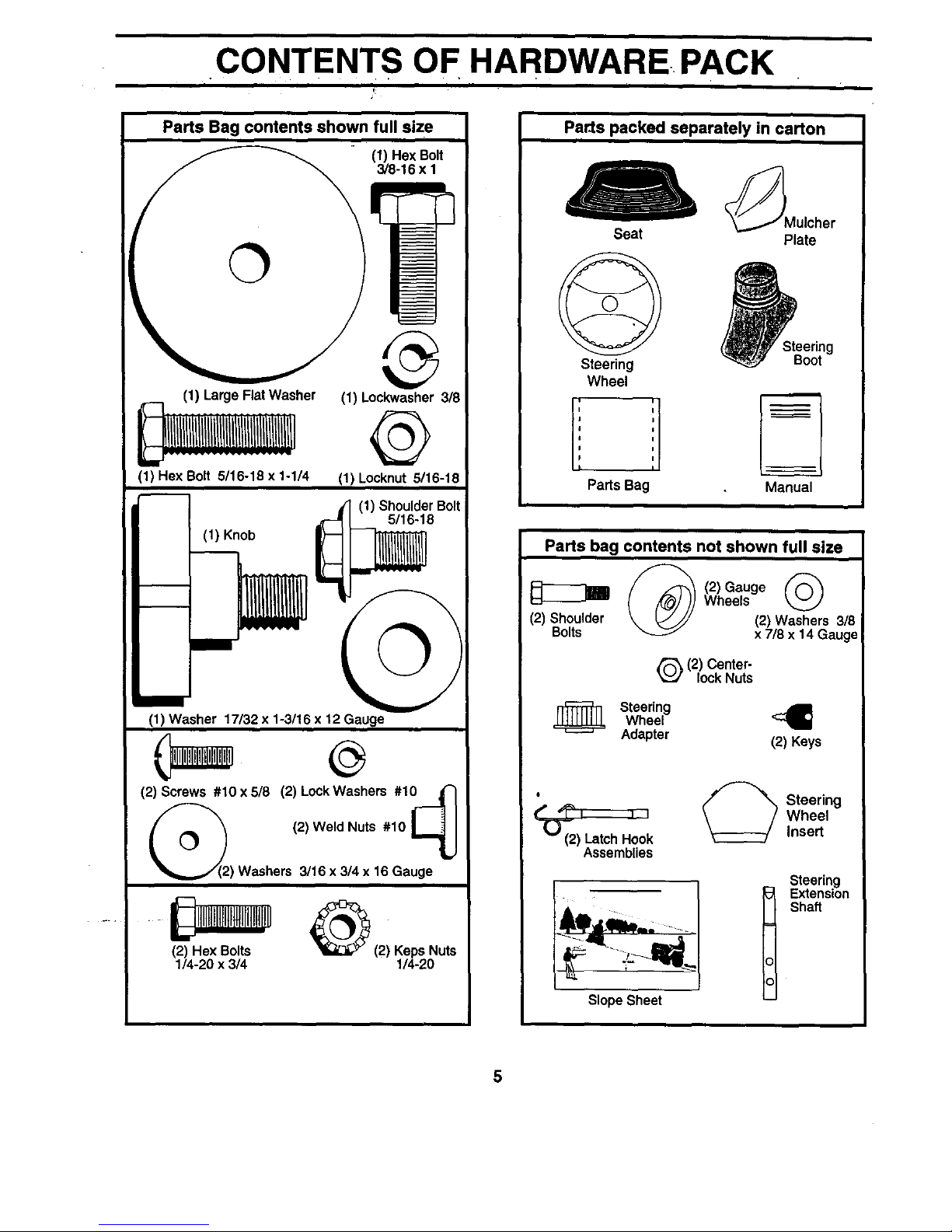
CONTENTS OF HARDWARE-. PACK
T
Parts Bag contents shown full size
(1) Hex Bolt
3/8-16 x 1
O
(1) Large Flat Washer
(1) Hex Bolt 5/16-18 x 1-1/4
(1) Knob
(1) Lockwasher 3/8
@
11)Locknut 6/16-18
(1) ShoulderBolt
5/16-18
©
R
(1) Washer 17132x 1-3/16 x 12 Gauge
(2) Screws #10 x5/8 (2) LockWashers #101 _
_2_we,d.uts.10I--_
c-31
"_...,,J(2) Washers 3/16 x 3/4 x 18 Gauge
(2) Hex Bolts Nuts
1/4-20 x 3/4 1/4-20
Parts packed separately in carton
_Mulcher
Seat Plate
Steering
Wheel
i i
;teering
Boot
Pa_s Bag Manual
Parts bag contents not shown full size
_ _2_Gauge
Wheels
(2) Shoulder (2) Washers 3/8
Bolts x 7/8 x 14 Gauge
Q(2) Center-
lockNuts
Steering
Wheel
Adapter (2) Keys
° Steering
W.ee,
(2) LatchHook Insert
Assemblies
SlopeSheet
Steering
Extension
Shaft
5
, ASSEMBLY
Your new tractorhas been assembled at the factory with exception ofthose parts left unassembled for shippingpurposes.
To ensure safe and properoperation ofyourtractor, all partsand hardware youassemble mustbe tightened securely. Use
the correct tools as necessary to insure proper tightness.
TOOLS REQUIRED FOR ASSEMBLY
A socket wrench setwill make assemblyeasier. Standard
• wrench sizes are listed.
(1) Phillipsscrewdriver Utility knife
(2) 7/16" wrenches Tire pressure gauge
(2) 1/2" wrenches (1) 3/4" socket with drive ratchet
(1) 9/16" wrenche
When right and left hand is mentioned in this manual, it
means when you are in the operating position (seated
behind the steering wheel).
TO REMOVE TRACTOR FROM CARTON
UNPACK CARTON
• Remove all accessible loose parts and parts cartons
from carton (See page 6).
• Cut, from topto bottom, along lines on allfour comers
of carton, and lay panels flat.
• Check for any additional loose parts or cartons and
remove.
BEFORE ROLLING TRACTOR OFF SKID
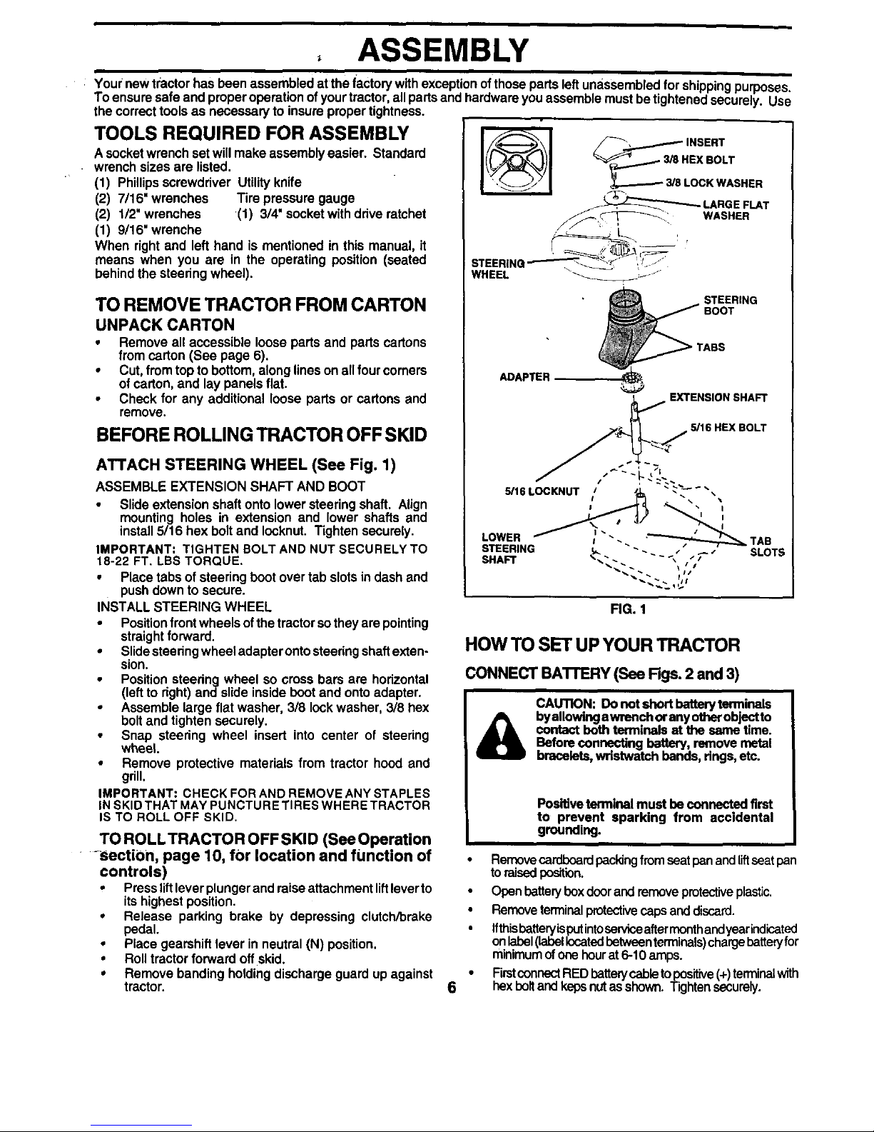
ATTACH STEERING WHEEL (See Fig. 1)
ASSEMBLE EXTENSION SHAFT AND BOOT
• Slide extension shaft onto lowersteedng shaft. Align
mounting holes in extension and lower shafts and
install5116 hex boltand Iocknut. Tighten securely.
IMPORTANT: TIGHTEN BOLT AND NUT SECURELY TO
18-22 FT. LBS TORQUE.
• Place tabs of steering boot over tab slotsin dash and
pushdown to secure.
INSTALL STEERING WHEEL
• Positionfront wheels ofthe tractor so theyare pointing
straightforward.
• Slide steeringwheel adapterontosteering shaftexten-
sion.
• Position steedng wheel so cross bars are horizontal
(leftto right)and slide insideboot and onto adapter.
• Assemble large flat washer, 3/8 lockwasher, 3/8 hex
bolt and tighten securely.
• Snap steering wheel insert into center of steering
wheel.
• Remove protective materials from tractor hood and
grill.
IMPORTANT: CHECK FOR AND REMOVE ANY STAPLES
INSKIDTHAT MAY PUNCTURE TIRES WHERE TRACTOR
IS TO ROLL OFF SKID.
TO ROLLTRACTOR OFFSKID (SeeOperation
-section, page 10, for location and function of
controls)
• Press liftlever plunger and raise attachment liftlever to
its highest position.
• Release parking brake by depressing clutch/brake
pedal.
• Place gearshiftlever in neutral (N) position.
• Roll tractor forward off skid.
• Remove banding holdingdischarge guard up against
tractor.
INSERT
EX BOLT
LOCK WASHER
LARGE FLAT
_ \_ WASHER
STEERINQ.--------_-_ _- ,j •
WHEEL _JJ
__ STEERING
BOOT
TASS
ADAPTER _
EXTENSION SHAFT
5/16 HEX BOLT
FIG. 1
HOW TO SET UP YOUR TRACTOR
CONNECTBA'FrERY (See Rgs. 2 and3)
CAUTION: Do not short batteryterminals
byallowingawrench orany otherobjectto
contact both terminals at the same time.
Beforeconnecting battery, remove metal
bracelets,wristwatch bends, rings,etc.
6
Positiveterminal must be connected first
to prevent sparking from accidental
grounding.
• Removecardboard packingfromseat pan andliftseat pan
toraisedposition.
• Open bettery boxdoor and removeprotectiveplastic.
• Removeterminalprotectivecapsanddiscard.
• Ifthisbetteryisputintoserviceaftermonthandyearindicated
onlabel(labellocatedbetweenterminals)chargebatteryfor
minimumofonehourat 6-10arnps.
• FirstconnectREDbetterycabletoposiUve(+)terminalwith
hexbolt and keps nutas shown. Tightensecurely.
i
ASSEMBLY
• connect BLACKgroundingcableto negative(-) terminal
withremaininghexboltandkeps nut. _ghten securely.
• Closebatteryboxdoor.
Open battery boxdoorfor:
• Inspection forsecureconnections(totightenhardware).
• Inspection forcorrosion.
• TesUngbattery.
• Jumping (ifrequired).
• Periodiccharging.
_ ISCARD
TERMINAL
PROTECTIVE
CAPS
KEPS
i
HEX BOLT
POSITIVE (RED) NEGATIVE
CABLE (BLACK)
CABLE
FIG, 2
SEAT
PAN
BOX DOOR
FIG. 3
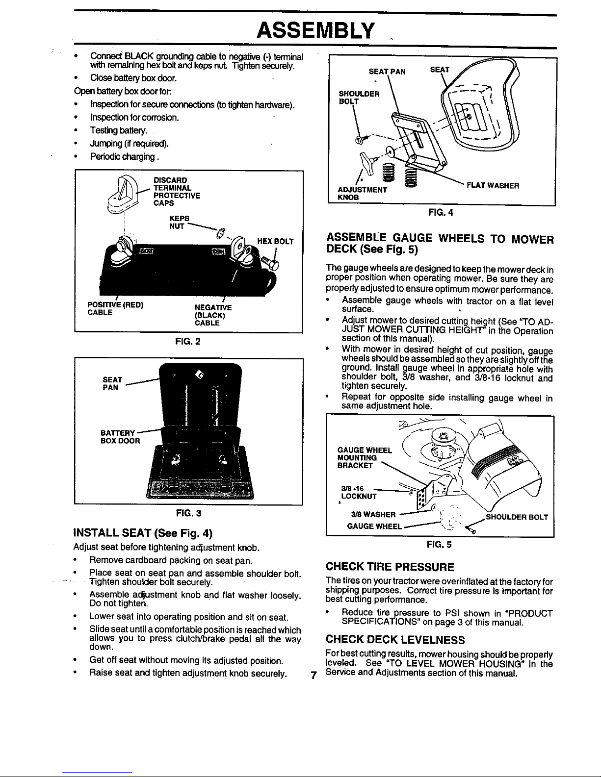
iNSTALL SEAT (See Fig. 4)
Adjust seat before tightening adjustment knob.
• Remove cardboard packing on seat pan.
Place seat on seat pan and assemble shoulder bo_t,
Tighten shoulder bolt securely.
Assemble adjustment knob and flat washer loosely.
Do not tighten.
Lower seat intooperating positionand sit onseat,
• Slide seat untila comfortableposition isreached which
allows you to press clutch/brake pedal all the way
down.
Get off seat without moving its adjusted position.
• Raise seat and tighten adjustment knob securely.
SEAT PAN SEAT
SHOULDER
BOLT
ADJUSTMENT
KNOB
FIG. 4
• FLAT WASHER
ASSEMBLE GAUGE WHEELS TO MOWER
DECK (See Fig. 5)
The gaugewheels are designed tokeep themower deck in
proper position when operating mower. Be sure they are
properlyadjusted toensure optimummowerperformance.
• Assemble gauge wheels with tractor on a flat level
surface.
• Adjust mowerto desired cuttinghei,,ght(See %0 AD-
JUST MOWER CU]-FING HEIGHT' in the Operation
sectionof thismanual).
• With mower in desired height of cut position, gauge
wheels shouldbe assembledsotheyare slightlyoffthe
ground. Install gauge wheel in appropriate hole with
shoulder bolt, 3/8 washer, and 3/8-16 Iocknut and
tighten securely.
• Repeat for opposite side installing gauge wheel in
same adjustmenthole.
GAUGE WHEEL
MOUNTING
BRACKET
7
3/8-16
LOCKNUT
I
3/S WASHER
ISHOULDER BOLT
GAU EWNEEL :
FIG. 5
CHECK TIRE PRESSURE
The tireson your tractorwere overinflated atthe factoryfor
shipping purposes. Correct tire pressure is importantfor
best cutting performance,
• Reduce tire pressure to PSi shown in "PRODUCT
SPECIFICATIONS on page 3 of this manual.
CHECK DECK LEVELNESS
Forbest cuttingresults, mowerhousingshould beproperly
leveled. See "TO LEVEL MOWER HOUSING" in the
Service and Adjustmentssection ofthis manual.
ASSEMBLY
CHECK FOR PROPER POSITION OF ALL
BELTS
See the figures that are shown for rep!acing motion and
mower blade drive belts in the Service and Adjustments
section of this manual. Verify that the belts are routed
correctly.
CHECK BRAKE SYSTEM
After you learn how to Operate your tractor,check to see
that the brake is propedy adjusted. See "TO ADJUST
BRAKE" in the Service and Adjustments section of this
manual.
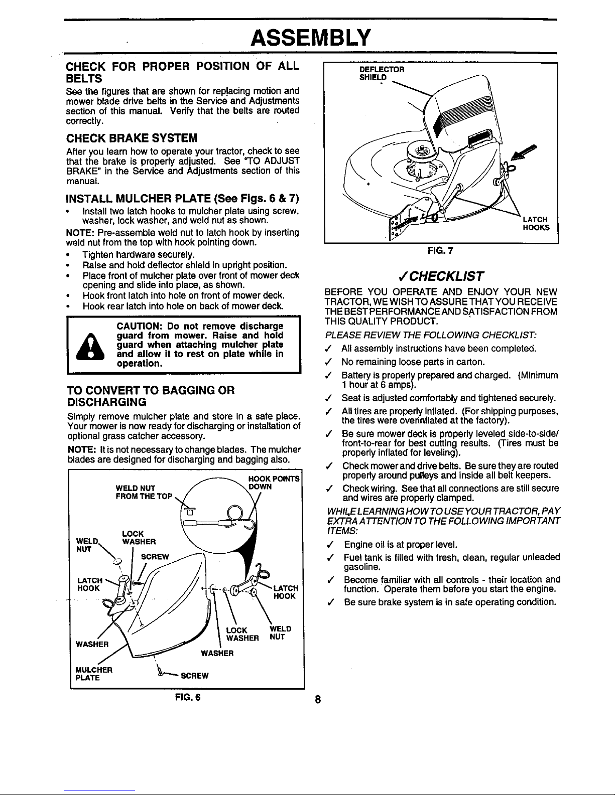
INSTALL MULCHER PLATE (See Figs. 6 & 7)
Install two latch hooks to mulcher plate using screw,
washer, lock washer, and weld nut as shown.
NOTE: Pre-assemble weld nut to latch hook by inserting
weld nutfrom the top withhook pointingdown.
• Tighten hardware securely.
• Raise and hold deflector shield in upright position.
• Place front of mulcher plate over frontof mower deck
opening and slide into place, as shown.
• Hook front latch into hole on front of mower deck.
• Hook rear latch into hole on back of mower deck.
A
CAUTION: Do not remove discharge
guard from mower. Raise and hold
guard when attaching mulcher plate
and allow it to rest on plate while in
operation.
TO CONVERT TO BAGGING OR
DISCHARGING
Simply remove mulcher plate and store in a safe place.
Your mower is now ready for discharging or installationof
optional grass catcher accessory.
NOTE: It is not necessaryto change blades. The mulcher
blades are designed for discharging and bagging also.
HOOK POINTS
WELD NUT DOWN
LOCK
WELD. WASHER
NUT _
'.23' SCREW
\
LATCH
HOOK
HOOK
WASHER
MULCHER
PLATE
LOCK WELD
WASHER NUT
DEFLECTOR
SHIELD
FIG. 7
LATCH
HOOKS
,/CHECKLIST
BEFORE YOU OPERATE AND ENJOY YOUR NEW
TRACTOR, WE WISH TO ASSURE THAT YOU RECEIVE
THE BESTPERFORMANCE AN DSATISFACTION FROM
THIS QUALITY PRODUCT.
PLEASE REVIEW THE FOLLOWING CHECKLIST:
,/ All assembly instructionshave been completed.
,/ No remaining loose partsin carton.
,/ Batteryis propedy prepared and charged. (Minimum
1 hourat 6 amps).
,/ Seat isadjusted comfortably andtightened securely.
,/ Alltiresare propedy inflated. (For shippingpurposes,
the tires were overinflatedat the factory).
•/ Be sure mower deck is properlyleveled side-to-side/
front-to-rear for best cutting results. (Tires must be
properly inflated for leveling).
/ Check mower anddrivebelts. Besure they are routed
properlyaround pulleys and inside all belt keepers.
/ Check wiring. See thatall connections are stillsecure
and wires are properlyclamped.
WI-tlt,ELEARNING HOW TO USE YOUR TRACTOR, PAY
EXTRA ATTENTION TO THE FOLLOWING IMPORTANT
ITEMS:
,/ Engine oil isat proper level.
,/ Fuel tank isfilled with fresh, clean, regular unleaded
gasoline.
,,/ Become familiar withall controls - their location and
function. Operate them before you startthe engine.
,/ Be sure brake system is in safe operating condition.
FIG. 6 8
OPERATION
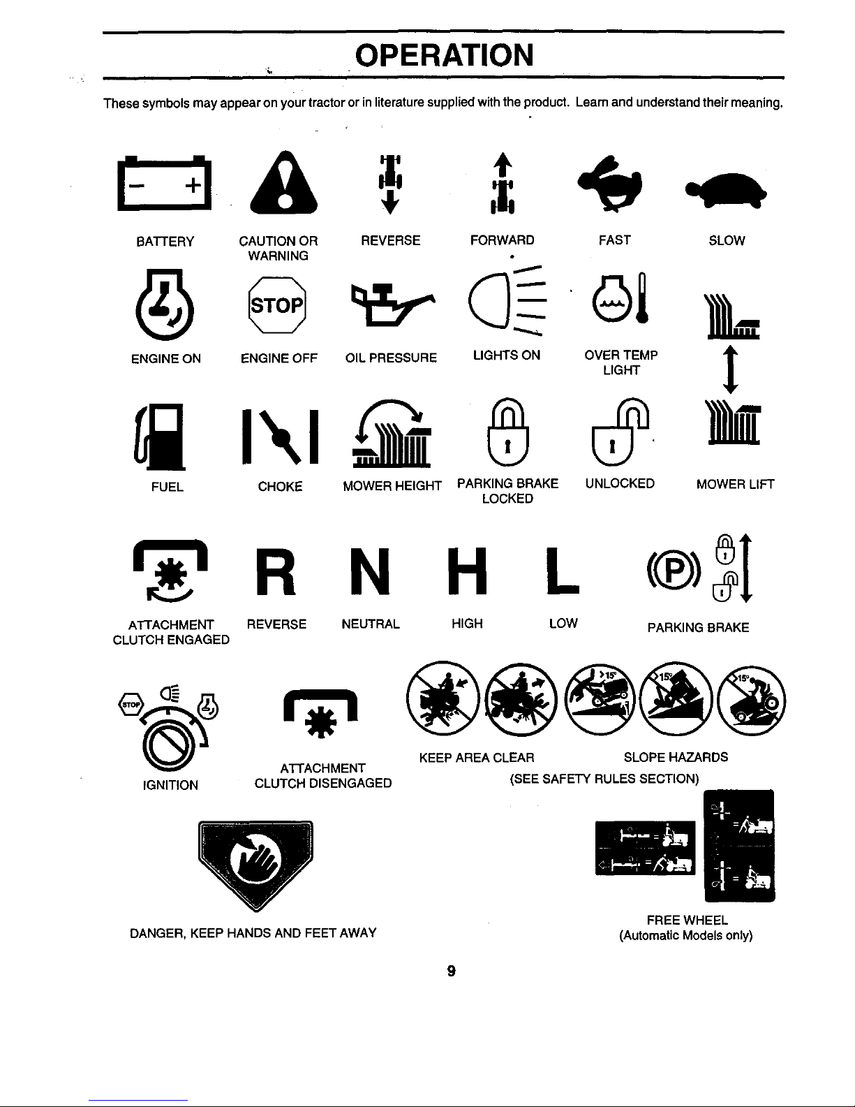
These symbolsmay appear on yourtractor or in literaturesuppliedwiththe product. Learn and understandtheir meaning.
BATTERY CAUTION OR REVERSE FORWARD FAST SLOW
WARNING
ENG,NEONENG,NEOFFO,LPRESSUREL.G._SONOV_,_E#PI
FUEL CHOKE MOWER HEIGHT PARKING BRAKE UNLOCKED MOWER LIFT
LOCKED
H L
ATTACHMENT REVERSE NEUTRAL HIGH LOW
CLUTCH ENGAGED
IGNITION
AI-I'ACHMENT
CLUTCH DISENGAGED
PARKING BRAKE
KEEP AREA CLEAR SLOPE HAZARDS
(SEE SAFETY RULES SECTION)
DANGER, KEEP HANDS AND FEET AWAY
FREE WHEEL
(Automatic Models only)
9
KNOW YOUR TRACTOR
OPERATION
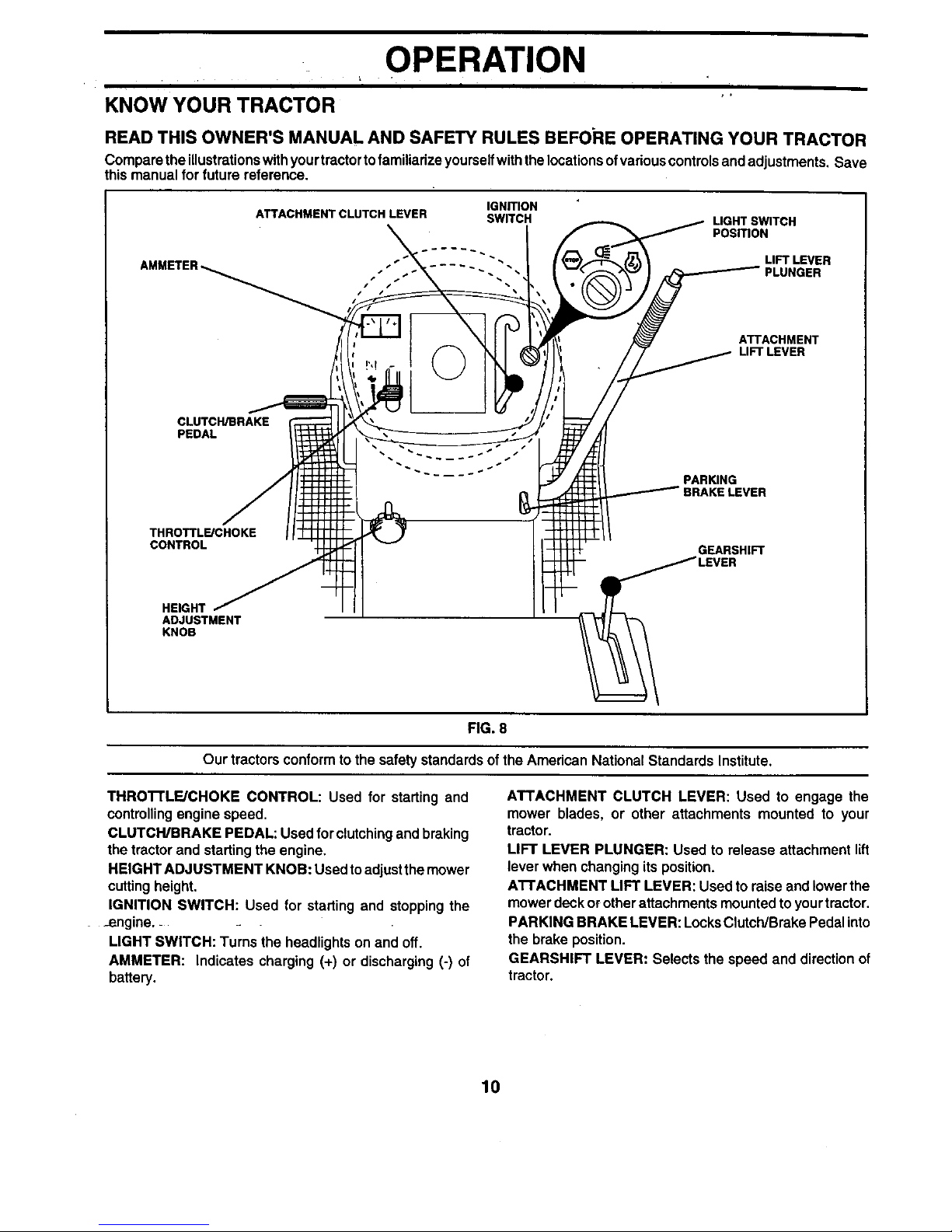
READ THIS OWNER'S MANUAL AND SAFETY RULES BEFORE OPERATING YOUR TRACTOR
Compare the illustrationswithyourtractortofamiliarizeyourselfwiththe locationsof variouscontrolsandadjustments, Save
this manual forfuture reference.
ATTACHMENT CLUTCH LEVER
IGNmON
SWITCH
LIGHTSWITCH
PosmoN
©
ATTACHMENT
LIFT LEVER
CLUTCH/BRAKE
PEDAL
PARffiNG
BRAKELEVER
THROTTL_CHOKE
CONTROL
GEARSHIFT
HEIGHT
ADJUSTMENT
KNOB
FIG. 8
Our tractors conform to the safety standardsof the American National Standards Institute.
THROI-rLFJCHOKE CONTROL: Used for starting and
controllingengine speed.
CLUTCWBRAKE PEDAL: Used for clutchingand braking
the tractorand starting the engine.
HEIGHT ADJUSTMENT KNOB: Used to adjustthe mower
cuttingheight.
IGNITION SWITCH: Used for starting and stopping the
_engine._
LIGHT SWITCH: Turns the headlights on and off.
AMMETER: Indicates charging (+) or discharging (-) of
battery.
ATTACHMENT CLUTCH LEVER: Used to engage the
mower blades, or other attachments mounted to your
tractor.
LIFT LEVER PLUNGER: Used to release attachment lift
lever when changingits position.
AI-I'ACHMENT LIFT LEVER: Used to raiseand lowerthe
mower deckor other attachments mounted toyour tractor.
PARKING BRAKE LEVER: LocksClutch/Brake Pedalinto
the brake position.
GEARSHIFT LEVER: Selects the speed and directionof
tractor.
10
OPERATION
The operationof anytractor can result in foreign objectsthrown intothe eyes, which can
resultin severeeye damage. Always wear safetyglasses or eye shields while operating
your tractor or performinganyadjustments or repairs. We recommenda wide vision
safety maskover spectacles or standard safetyglasses.
HOW TO USE YOUR TRACTOR
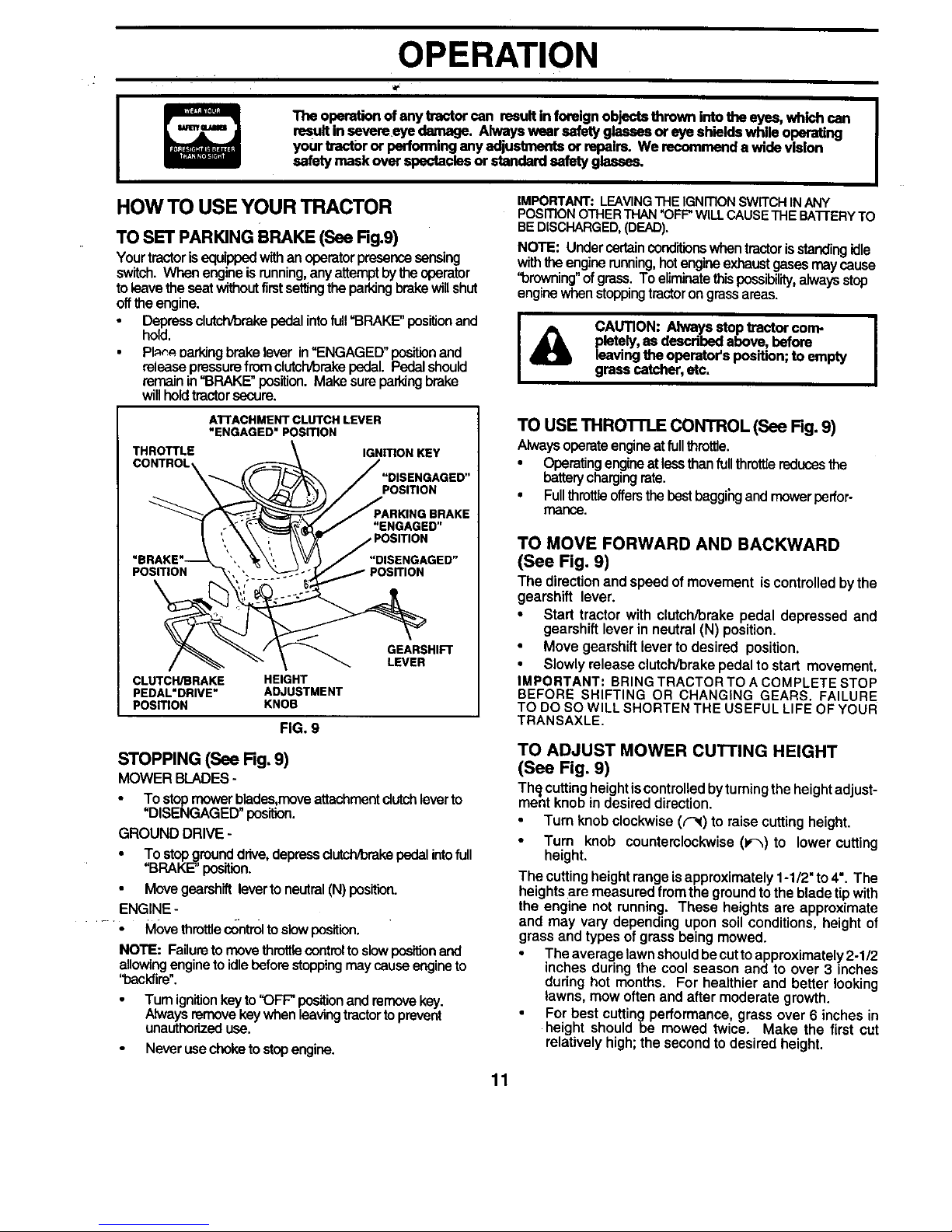
TO SET PARKING BRAKE (See Rg.9)
Yourtractorisequippedwithan operatorpresence sensing
switch.When engineisrunning,any attemptbythe operator
toleavetheseat withoutfirstsettingthe parkingbrakewillshut
offthe engine.
• Depressclutch/brakepedalintofull"BRAKE"positionand
hold.
• PI_. oarkingbrakelever in"ENGAGED" positionand
releasepressurefrom clutch/brekepedal. Pedalshould
remainin"BRAKE" position. Make sureparldngbrake
willholdtractorsecure.
ATTACHMENT CLUTCH LEVER
"ENGAGED" POSITION
THROTTLE IGNITIONKEY
CONTROL
POSITION
POSITION
"ENGAGED"
"DISENGAGED"
POSITION
CLUTCH/BRAKE HEIGHT
PEDAL'DRIVE" ADJUSTMENT
POSITION KNOB
FIG. 9
GEARSHIFT
LEVER
STOPPING (See Fig, 9)
MOWER BLADES-
To stopmowerblades,moveattachmentdutch leverto
"DISENGAGED" position.
GROUND DRIVE -
• To stepgrounddrive,depressdutch/brakepedalintofull
"BRAKE" position.
Move gearshift lever to neutral (N) position.
ENGINE -
.... • Movethrottle controltoslowposition.
NOTE: Failuretomove throttlecontroltoslowposition and
allowingengineto idlebeforestoppingmay causeengineto
"backfire".
Turnignitionkey to"OFF position and removekey.
Alwaysremovekeywhen leavingtractorto prevent
unauthorizeduse.
Never use choketo stepengine.
IMPORTANT:LEAVINGTHEIGNmONSWITCHINANY
PosmoN OTHERTHAN"OFF"WILLCAUSETHEBA'I-rERYTO
BEDISCHARGED,(DEAD).
NOTE: Under certainconditionswhen tractor is standing idle
with the enginerunning,hot engine exhaust gases may cause
"browning"of grass. To eliminate this possibility,always stop
engine when stopping tractorongrass areas.
J_ CAUTION: Always stoptractor com- I
pletely,as described above, before
leavingthe operator's position;to empty
grass catcher, etc.
TO USE THROI'TLE CONTROL (See Rg. 9)
Alwaysoperateengineatfullthrottle.
• Operating engineat lessthan full throttlereducesthe
batterychargingrate.
• Fullthrottle offersthebestbaggihg andmower perfor-
mar'Ice.
TO MOVE FORWARD AND BACKWARD
(See Fig. 9)
The directionand speed of movement iscontrolledbythe
gearshift lever.
• Start tractor with clutch/brake pedal depressed and
gearshift lever in neutral (N) position,
• Move gearshift lever to desired position.
• Slowly release clutch/brake pedalto start movement.
IMPORTANT: BRING TRACTOR TO A COMPLETE STOP
BEFORE SHIFTING OR CHANGING GEARS, FAILURE
TO DO SOWILL SHORTEN THE USEFUL LIFE OF YOUR
TRANSAXLE.
TO ADJUST MOWER CUTTING HEIGHT
(See Fig. 9)
Th_ cuttingheightiscontrolledby turningthe heightadjust-
ment knob in desired direction.
Turn knobclockwise (('_) to raise cuttingheight.
• Turn knob counterclockwise(1,-_) to lower cutting
height.
The cuttingheightrange isapproximately1-1/2" to4". The
heightsare measured from the groundtothe bladetip with
the engine not running. These heights are approximate
and may vary depending upon soil conditions,height of
grass and types of grass beingmowed.
The average lawnshouldbecutto approximately2-1/2
inches during the cool season and to over 3 inches
during hot months. For healthier and better looking
lawns, mow often and after moderate growth.
For best cuttingperformance, grass over 6 inches in
height shouldbe mowed twice. Make the first cut
relatively high; the second to desired height.
11
OPERATION
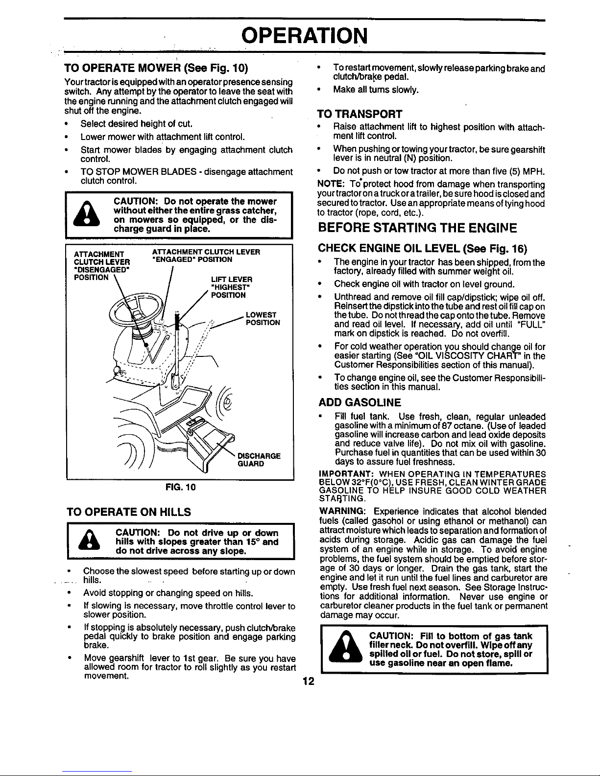
TO OPERATE MOWER (See Fig. 10)
Yourtractor isequippedwithan operatorpresencesensing
switch. Any attempt by the operator to leave the seat with
theengine runningand the attachment clutchengaged will
shut offthe engine.
• Select desired height of cut.
• Lower mower with attachment liftcontrol.
• Start mower blades by engaging attachment Clutch
control.
• TO STOP MOWER BLADES - disengage attachment
clutch control.
&
CAUTION: Do not operate the mower
without either the entire grass catcher,
on mowers so equipped, or the dis-
charge guard in place.
ATTACHMENT
CLUTCH LEVER
"DISENGAGED"
POSITION
ATTACHMENT CLUTCH LEVER
"ENGAGED" POSITION
LIFT LEVER
"HIGHEST"
POSITION
LOWEST
POSITION
/,'
,J
GUARD
FIG. 10
TO OPERATE ON HILLS
I & CAUTION: Do not drive up or down I
hills with slopes greater than 15° and
do not drive across any slops.
Choose the slowest speed before startingupor down
hills.
Avoid stopping or changing speed on hills.
If slowing is necessary, move throttle controllever to
slower position.
If stoppingis absolutely necessary, pushclutch/brake
pedal quickly to brake position and engage parking
brake.
Move gearshift lever to 1st gear. Be sure you have
allowed room for tractor to rollslightly as you restart
movement.
• To restartmovement, slowlyrelease parkingbrake and
clutch/brake pedal.
• Make allturns slowly.
TO TRANSPORT
• Raise attachment lift to highest position with attach-
ment liftcontrol.
• When pushing ortowingyour tractor, be sure gearshift
lever isin neutral (N) position.
• Do not push or tow tractor at more than five (5) MPH.
NOTE: To'protect hood from damage when transporting
yourtractoron atruckora trailer,be sure hoodisclosed and
securedto tractor. Useanappropriate means oftyinghood
to tractor (rope, cord, etc.).
BEFORE STARTING THE ENGINE
CHECK ENGINE OIL LEVEL (See Fig. 16)
The engine inyourtractor hasbeen shipped, from the
factory, already filled withsummer weight oil.
Check engine oilwith tractoron level ground.
Unthread and remove oilfill cap/dipstick; wipe oil off.
Reinsertthe dipstickintothe tubeand restoilfill capon
thetube. Do notthread the cap onto thetube. Remove
and read oil level. If necessary, add oil until "FULL"
mark on dipstick is reached. Do not overfill.
For cold weather operation you should change oil for
easier starting (See "OIL VISCOSITY CHART" in the
Customer Responsibilities section of this manual).
To change engine oil, see the Customer Responsibili-
ties section in this manual.
ADD GASOLINE
• Fill fuel tank. Use fresh, clean, regular unleaded
gasolinewitha minimumof87 octane. (Use of leaded
gasoline will increasecarbon and lead oxide deposits
and reduce valve life). Do not mix oil with gasoline.
Purchase fuel inquantities that can be used within30
days to assurefuel freshness.
IMPORTANT: WHEN OPERATING IN TEMPERATURES
BELOW32°F(0°C), USE FRESH, CLEANWINTER GRADE
GASOLINE TO HELP INSURE GOOD COLD WEATHER
STAFJTING.
WARNING: Experience indicates that alcohol blended
fuels (called gasohol or using ethanol or methanol) can
attract moisturewhichleads toseparation and formation of
acids during storage. Acidic gas can damage the fuel
system of an engine while in storage. To avoid engine
problems, the fuel system should be emptied before stor-
age of 30 days or longer. Drain the gas tank, start the
engine and let it rununtilthe fuel lines and carburetorare
empty. Use fresh fuel nextseason. See Storage Instruc-
tions for additional information. Never use engine or
carburetorcleaner productsin the fuel tank or permanent
damage may occur.
I
CAUTION: Fill to bottom of gas tank
filler neck. Do not overfill. Wipe off any
spilled oil or fuel. Do not store, spill or
use gasoline near an open flame.
12
OPERATION
TO START ENGINE (See Fig. 9) •
When startingthe engine for the firsttime or ifthe engine
has runout of fuel, it will take extra crankingtime to move
fuel from the tank to the engine. •
• Sit on seat inoperating position,depress clutch/brake
pedal and set parking brake.
• Place gear shiftlever in neutral (N) position. •
• Move attachment clutchto =DISENGAGED" position.
• Move throttle control to choke position.
NOTE: Before starting, read the warm and cold starting
procedures below. •
• Insert keyinto ignition and turn keyclockwiseto "START"
position and release key as soon as engine starts. Do
not run starter continuously for more than fifteen sec-
onds per minute, if the engine does "lot start after
several attempts, move throttle control to fast position,
wait afew minutes andtry again. If engine stilldoes not
start, move the throttle control back to the choke
position and retry.
WARM WEATHER STARTING (50° F and above)
• When engine starts, move the throttle controltothe fast
position.
• The attachments and ground drive can nowbe used. If
the engine does not accept the load, restart the engine
and allow itto warm up for one minute using the choke
as described above.
COLD WEATHER STARTING ( 50° F and below)
• When engine starts, allowengine to runwith thethrottle
control in the choke position until the engine runs
roughly, then movethrottle control tofast position. This
may require an engine warm-up period from several
seconds to several minutes, depending on the tem-
perature.
• The attachments can also be used during the engine
warm-up period.
NOTE: If at a high altitude (above 3000 feet) or in cold
temperatures (below 32 F) the carburetor fuel mixture may
need to be adjusted for best engine performance. See "TO
ADJUST CARBURETOR" in the Service and Adjustments
section of this manual.
MOWINGTIPS
Tire chains cannot be used when the mower housing
is attached to tractor.
• Mower should be properly leveled for best mowing
performance. See "TO LEVEL MOWER HOUSING" in
the Service and Adjustments section of this manual.
The left hand side of mower should be used for trim-
ming.
Drive so that clipPings are discharged onto the area
that has been cut. Have the cut area to the right of the
machine. This will result in a more even distnbution of
clippings and more uniform cutting.
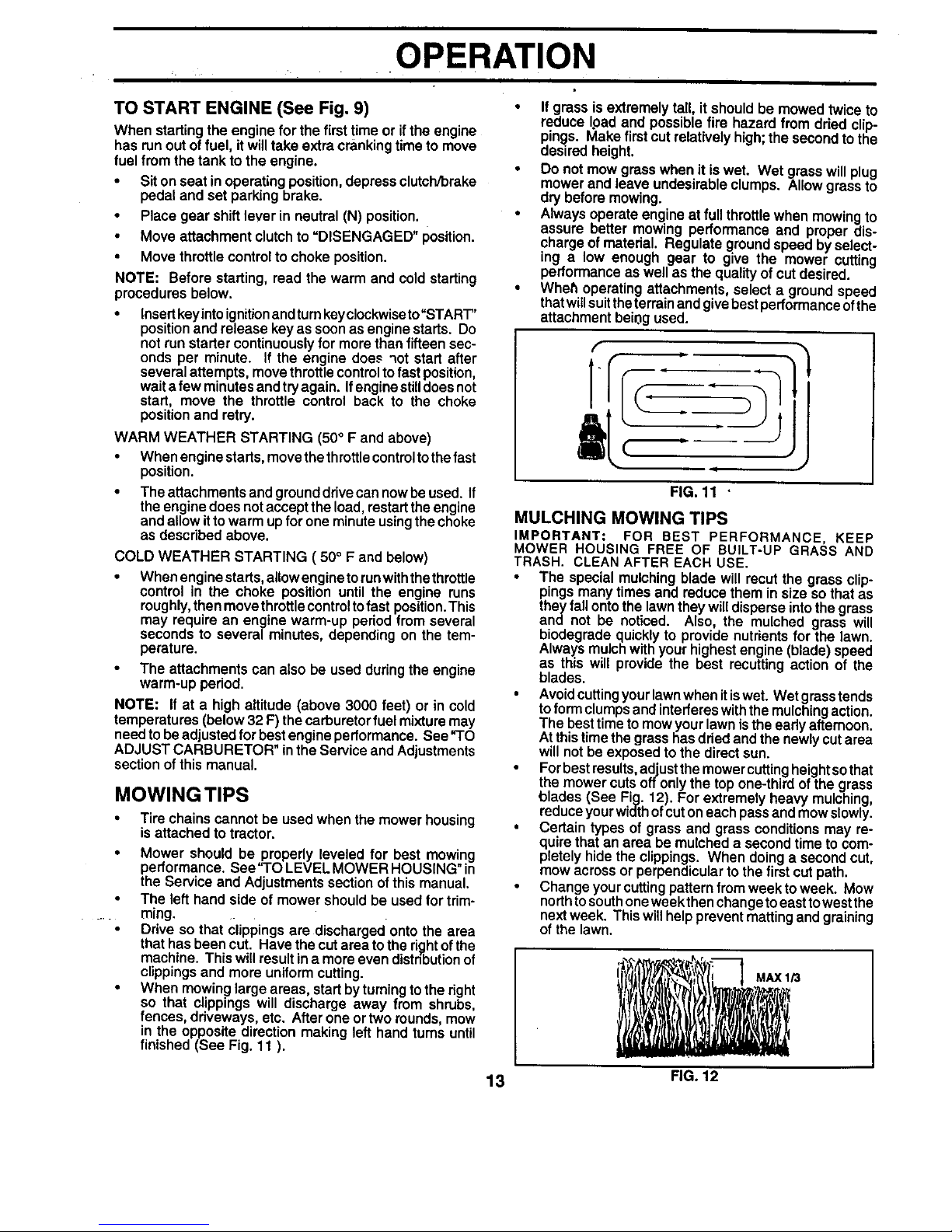
• When mowing large areas, start by turning to the right
so that clippings will discharge away from shrubs,
fences, driveways, etc. After one or two rounds, mow
in the opposite direction making left hand turns until
finished (See Fig. 11 ).
If grass is extremely tall, itshould be mowed twice to
reduce Ipad and possible fire hazard from dried clip-
pings. Make first cut relatively high the second to the
des red he ght.
Do not mow grass when it is wet. Wet grass will plug
mower and leave undesirable clumps. Allow grass to
dry before mowing.
Always operate engine atfull throttle when mowing to
assure better mowing performance and proper dis-
charge of material. Regulate ground speed by select-
ing a low enough gear to give the mower cutting
performance as well as the quality of cutdesired.
Wheh operating attachments, select a ground speed
that will suit the terrain and give best performance of the
attachment bei0g used.
FIG. 11 "
MULCHING MOWING TIPS
IMPORTANT: FOR BEST PERFORMANCE, KEEP
MOWER HOUSING FREE OF BUILT-UP GRASS AND
TRASH. CLEAN AFTER EACH USE.
• The special mulching blade will recut the grass clip-
pings many times and reduce them in size so that as
they fall onto the lawn they will disperse into the grass
and not be noticed. Also, the mulched grass will
biodegrade quickly to provide nutrients for the lawn.
Always mulch with your highest engine (blade) speed
as this will provide the best recutting action of the
blades.
• Avoidcuttingyour lawnwhen itiswet. Wet grasstends
to form clumpsand interfereswiththe mulchingaction.
The besttimeto mowyourlawn isthe early afternoon.
At thistime the grasshas dried and thenewly cut area
will not be exposedto the directsun.
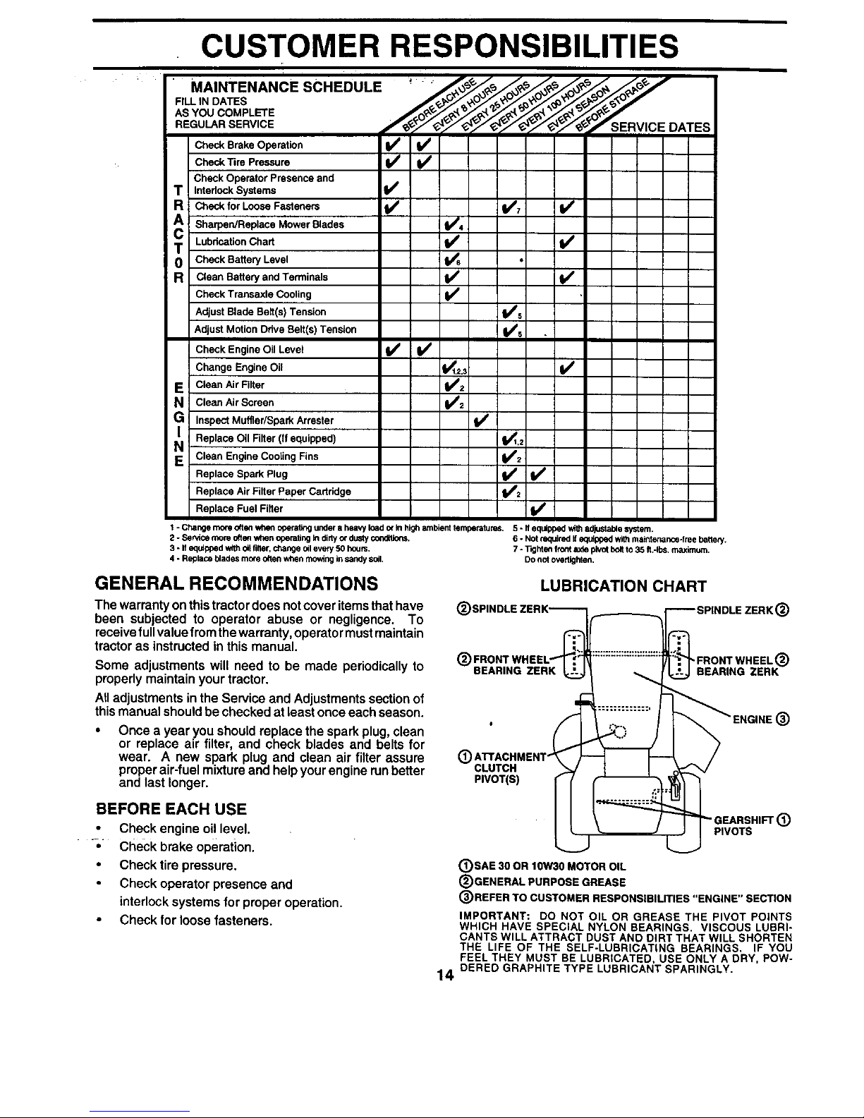
• For bestresults,adjustthe mowercuttingheightsothat
the mower cutsoffonly the top one-third of the grass
_lades (See Fig. 12). For extremely heavy mulching
reduce your width of cuton each pass and mow slowly.
• Certain types of grass and grass conditions may re-
quire that an area be mulched a second time to com-
pletely hide the clippings. When doing a second cut,
mow across or perpendicular to the first cut path.
• Change your cutting pattern from weekto week. Mow
north to south one week then change to eastto west the
next week. This will help prevent matting and graining
of the lawn.
13 FIG. 12
CUSTOMER RESPONSIBILITIES
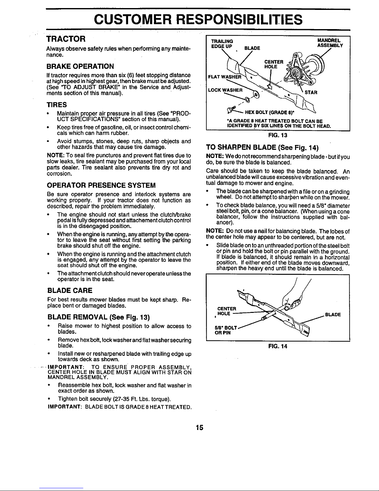
MAINTENANCE SCHEDULE _ " '_,_ ",/_,_s/_ _/_,_/_ _//_"_
AS YOU COMPLETE _v _,_ _ _'/_'_'_q'_'_'_'_'_'_,_""
REGU 'RSERV,CE
:::c:Bg:;o::::,on
Check Operator Presence and
T Interlock Systems
R Check for Loose Fasteners l_ V/7 V _
A Sharpen/Replace Mower Blades i4
t Lubrication Chart V'
0 Check Battery Level
R Clean Battery and Terminals !_
Check Transaxle Cooling I_
Adjust Blade Belt(s) Tension I_s
Adjust Motion Drive Belt(s) Tension V's
Check Engine Oil Level V' If
Change Engine Oil _2.3 V P
E Clean Air Filter _:
N Clean Air Screen
i/
G Inspect Muffler/Spark Arraster
N Replace Oil Filter (If equipped) 11_1.2
Clean Engine Cooling Fins V'2
Replace Spark Plug _V'2 V_
Replace Air Filter Paper Cartddge
Replace Fuel Filter ll_
1* Change more ottetl wheneperating under a heaw loador_ hi_nP,mbienttemperatures. 5 -If equipped v/_thedjustable syslam.
2 - Se_ce more otlan when operatingIn dirtyor dusty cond_ons. 6 -Not requiredifequippedwithmaintenance-freebattery,
S - If eputpped w#h oltfiner,ot_angedil eveP/50 hours. 7 -"l-_htenfm_t axle pivotbditto 35 ft,-Ibs, maximum.
4 - Replace blades more o(ten whenmowinginsandy soil, Donot overUghten,
GENERAL RECOMMENDATIONS
LUBRICATION CHART
The warrantyon thistractordoes notcoveritems that have @
been subjected to operator abuse or negligence. To
receivefull value fromthe warranty, operatormustmaintain
tractor as instructed in this manual.
@
Some adjustments will need to be made periodically to
properly maintain your tractor.
Alladjustments in the Service and Adjustmentssection of
thismanual should be checked at leastonce each season.
BEARING ZERK
Once a year you should replace the sparkplug, clean
or replace air filter, and check blades and belts for
wear. A new spark plug and clean air filter assure (_)
properair-fuel mixture and helpyour engine runbetter CLUTCH
and last longer. PIVOT(S)
@
'FRONT WHEEL@
BEARING ZERK
®
BEFORE EACH USE
Check engine oil level.
-;, Check brake operation.
• Check tire pressure.
Check operator presence and
interlock systems for properoperation.
Check forloose fasteners.
IEARSHIFT@
PIVOTS
(_)SAE 30 OR lOW30 MOTOR OIL
@GENERAL PURPOSE GREASE
@REFER TO CUSTOMER RESPONSIBILITIES "ENGINE" SECTION
IMPORTANT: DO NOT OIL OR GREASE THE PIVOT POINTS
WHICH HAVE SPECIAL NYLON BEARINGS. VISCOUS LUBRI-
CANTS WILL ATTRACT DUST AND DIRT THAT WILL SHORTEN
THE LIFE OF THE SELF-LUBRICATING BEARINGS. IF YOU
FEEL THEY MUST BE LUBRICATED, USE ONLY A DRY, POW-
14 DERED GRAPHITE TYPE LUBRICANT SPARINGLY.
CUSTOMER RESPONSIBILITIES
TRACTOR
Always observe safety ruleswhen performing any mainte-
nance.
BRAKE OPERATION
Iftractor requires morethan six (6)feet stoppingdistance
at highspeed inhighestgear, then brake mustbe adjusted.
(See "TO ADJUST BRAKE" in the Service and Adjust-
ments section of this manual).
TIRES
• Maintain proper air pressure in all tires (See =PROD-
UCT SPECIFICATIONS" section of this manual).
• Keep tiresfree of gasoline,oil, or insectcontrolchemi-
cals which can harm rubber.
Avoid stumps, stones, deep ruts, sharp objects and
other hazards that may cause tire damage.
NOTE; To seal tire punctures and prevent flat tires due to
slow leaks, tire sealant may be purchased from your local
parts dealer. Tire sealant also prevents tire dry rot and
corrosion.
OPERATOR PRESENCE SYSTEM
Be sure operator presence and interlock systems are
working properly. If your tractor does not function as
described, repairthe problem immediately.
• The engine should not start unless the clutch/brake
pedalisfully depressedand attachementclutchcontrol
isin the disengaged position.
• When theengine is running,any attemptbythe opera-
tor to leave the seat without first settingthe parking
brake shouldshut offthe engine.
• When the engine isrunning and the attachmentclutch
is engaged, any attempt by the operatorto leave the
seat should shut off the engine.
• The attachment clutchshouldneveroperate unlessthe
operator is in the seat.
BLADE CARE
For best results mower blades must be kept sharp. Re-
place bent or damaged blades.
BLADE REMOVAL (See Fig. 13)
• Raise mower to highest positionto allow access to
blades.
• Remove hexbolt, lockwasherandflat washer secudng
blade.
• Install new or resharpened blade with trailing edge up
towards deck as shown.
---IMPORTANT: TO ENSURE PROPER ASSEMBLY,
CENTER HOLE IN BLADE MUST ALIGN WITH STAR ON
MANDREL ASSEMBLY.
• Reassemble hex bolt, lock washer and flat washer in
exact order as shown.
• Tighten bolt securely (27-35 Ft. Lbs. torque).
IMPORTANT: BLADE BOLTIS GRADE8 HEATTREATED.
TRAILING
EDGE UP
\
FLAT WASHEF
BLADE
CENTER
HOLE
MANDREL
ASSEMBLY
LOCK WASHER
_'.- HEX BOLT (GRADE 8)*
*A GRADE 8 HEAT TREATED BOLT CAN BE
IDENTIFIED BY SiX LINES ON THE BOLT HEAD
FIG. 13
TO SHARPEN BLADE (See Fig. 14)
NOTE: We do notrecommend sharpeningblade - butifyou
do, be sure the blade is balanced.
Care should be taken to keep the blade balanced. An
unbalanced blade will cause excessive vibration and even-
tual damage to mower and engine.
• The blade can be sharpened with a file or on agdnding
wheel. Do not attempt to sharpen while on the mower.
• To check blade balance, you will need a 5/8" diameter
steel bolt, pin, ora cone balancer. (When using a cone
balancer, follow the instructions supplied with bal-
ancer).
NOTE: Do not use a nail for balancing blade. The lobes of
the center hole may appear to be centered, but are not.
• Slide blade on to an unthreaded portion of the steel bolt
or pin and hold the bolt or pin parallel with the ground.
If blade is balanced, it should remain in a horizontal
position. Ifeither end of the blade moves downward,
sharpen the heavy end until the blade is balanced.
CENTER '_
OR PIN
FIG. 14
15
CUSTOMER RESPONSIBILITIES
BATrERY
Your tractor has a battery chargingsystem which issuffi-
cient for normal use. However, period!c charging of the
battery with an automotive charger willextend its life.
• Keep battery and terminals clean.
• Keep battery boltstight.
• Keep small vent holes open.
• Recharge at 6-10 amperes for 1 hour.
TO CLEAN BA'I-IERY AND TERMINALS
Corrosionand dirton the battery and terminals can cause
the battery to "leak" power.
• Open battery box door.
• Disconnect BLACK battery cable first then RED bat-
tery cable and remove batteryfrom tractor.
Rinse the battery withplain water and dry.
Clean terminals and batterycable ends withwire brush
until bright.
• Coat terminals with grease or petroleum jelly.
• Reinstall battery (See "CONNECT BATI'ERY" in the
Assembly sectionof this manual).
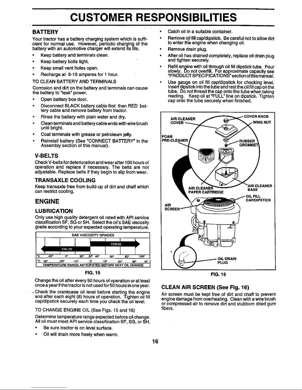
• Catch oil ina suitable container.
• Remove oilfillcap/dipstick. Be careful nottoallow dirt
to enter the engine whenchanging oil.
• Remove drain plug.
• After oilhas drained completely, replace oildrain plug
and tightensecurely.
Refill engine with oil throughoil filldipsticktube. Pour
slowly. Do not overfill For approximate capacity see
"PRODUCT SPECIFICATIONS" sectionofthismanual.
• Use gauge on oil fill cap/dipstick for checking level.
Insertdipstickintothetube and resttheoilfillcaponthe
tube. Do notthread the cap onto the tube when taking
reading. Keep oil at "FULL" line ondipstick. Tighten
cap onto the tube securely when finished.
AIR CLEANER
,WING NUT
V-BELTS
Check V-belts fordeterioration and wear after 100hoursof
operation and replace if necessary. The belts are not
adjustable. Replace belts if they begin to slip from wear.
TRANSAXLE COOLING
Keep trensaxle free from build-up of dirtand chaff which
can restrictcooling. PAPER CARTRIDGE
3LEANER
BASE
ENGINE
CAP/DIPSTICK
LUBRICATION
Only use high quality detergent oil ratedwith API service
classificationSF, SG or SH. Select the oil'sSAE viscosity
grade according toyour expected operatingtemperature.
SAE VISCOSITY GRADES
-20* 0 ° 30* 32 ° 40 _ 60" 80 °
-30" -20 ° -I0 ° O" 10 ° 20 ° 30 ° 40 °
TEMPERATURE RANGE ANTICIPATED BEFORE NEXT OIL CHANGE
FIG° 15
PLUG
Change the oil after every 50 hours ofoperation or at least
once ayear if the tractor is not used for 50 hours in one year.
--Check the crankcase oil level before starting the engine
and after each eight (8) hours of operation. Tighten oilfill
cap/dipstick securely each time you check the oil level.
TO CHANGE ENGINE OIL (See Figs. 15 and 16)
Determine temperature range expected before oil change.
All oil must meet API service classificationSF, SG, or SH.
• Be sure tractor is on level surface.
• Oil will drain more freely when warm.
FIG. 16
CLEAN AIR SCREEN (See Fig. 16)
Air screen must be kept free of dirt and chaff to prevent
engine damage from overheating. Clean witha wire brush
or compressed air to remove dirt and stubborndriedgum
fibers.
16
CUSTOMER RESPONSIBILITIES
AIR FILTER (See Fig. 16) MUFFLER
Your engine will not run properly using a dirty air filter.
Clean the foam pre-cleaner after every 25 hours ofopera-
tion or every season. Service paper cartridge every 100
hoursofoperationor every season,whichever occursfirst.
Service aircleaner more often under dustyconditions.
Remove knob and cover.
• Remove wing nut and air cleaner from base.
TO SERVICE PRE-CLEANER
Slide foam pre-cleaner off cartridge.
Wash it in liquid detergent and water.
Squeeze it dry in a clean cloth. Allow it to dry.
• Saturate it in engine oil. Wrap it in clean, absorbent
cloth and squeeze to remove excess oil.
TO SERVICE CARTRIDGE
• Replace a dirty, bent, or damaged cartridge.
NOTE: Do not wash the paper cartridge or use pressurized
air, as this will damage the cartridge.
• Reinstall the pre-cleaner (cleaned and oiled) over the
paper cartridge.
Reassemble air cleaner, wing nut, cover and tighten
knob securely.
CLEAN AIR INTAKE/COOLING AREAS
To insure proper cooling, make sure the grass screen,
coolingfins, and other external surfaces ofthe engine are
kept clean at all times.
Every 100 hours of operation (more often under extremely
dusty, dirty conditions), remove the blower housing and
othercooling shrouds. Clean the coolingfins and external
surfacesas necessary. Make surethe coolingshroudsare
reinstalled.
NOTE: Operetingthe enginewitha blockedgrass screen,
dirty or plugged cooling fins, and/or cooling shrouds re-
moved willcause engine damage due to overheating.
Inspect and replace corroded muffler and spark arrester (if
equipped) as itcouldcreate a fire hazard and/or damage.
SPARKPLUGS
Replace spark plugs at the beginning of each mowing
season or after every 100 hours ofuse, whichevercomes
first. Spark plugtype and gap setting isshown in"PROD-
UCT SPECIFICATIONS" section of this manual.
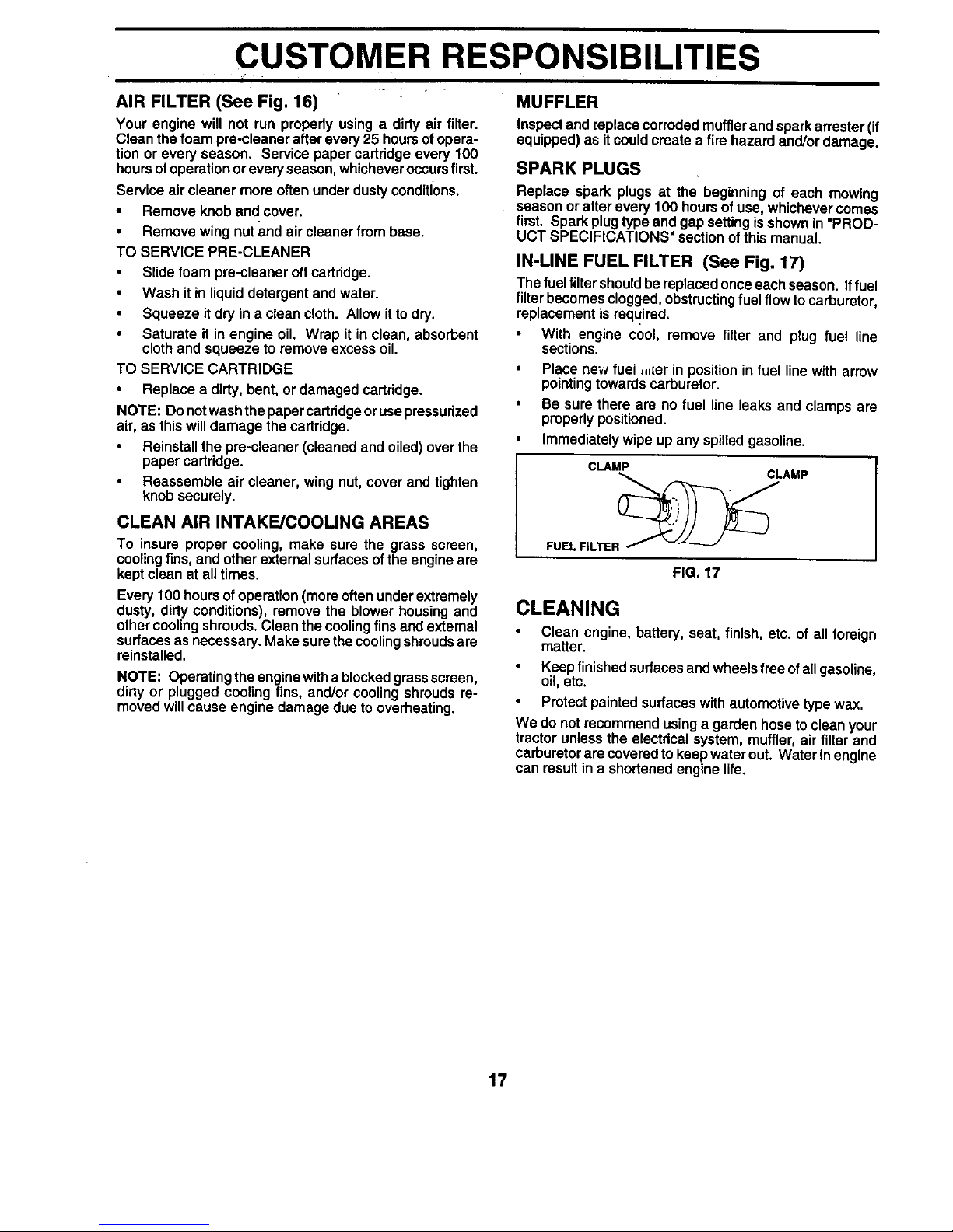
IN-LINE FUEL FILTER (See Fig, 17)
The fuel filtershouldbe replaced onceeach season. Iffuel
filter becomesclogged, obstructingfuel flow tocarburetor,
replacement is required.
With engine cool, remove filter and plug fuel line
sections.
Place new fuel ,,,{er in position in fuel line with arrow
pointingtowards carburetor.
Be sure there are no fuel line leaks and clamps are
properly positioned.
Immediately wipe up any spilledgasoline.
CLAMP
FUEL RLTER _AMP
FIG. 17
CLEANING
• Clean engine, battery, seat, finish, etc. of all foreign
matter.
• Keep finished surfacesand wheels free ofall gasoline,
oil, etc.
• Protect painted surfaces with automotivetype wax.
We do not recommend using a garden hose toclean your
tractor unless the electrical system, muffler, air filter and
carburetor are coveredto keep water out. Water inengine
can resultin a shortenedengine life.
17
 Loading...