

Craftsman 944.609150 Owner's Manual
SEARS
OWNER'S
MANUAL
MODEL NO.
944.609150
Caution:
Read and follow
all Safety Rules
and Instruct,ons
Before Operating
Thts Equ,pment
(R;IFTZMrlNo
15.5 HP
ELECTRIC START
36" MOWER
AUTOMATIC
LAWN TRACTOR
• Assembly
• Operation
• Customer Responsibilities
• Service and Adjustments
• Repair Parts
Sears Canada, Inc., Toronto, Ontario M5B 2B8
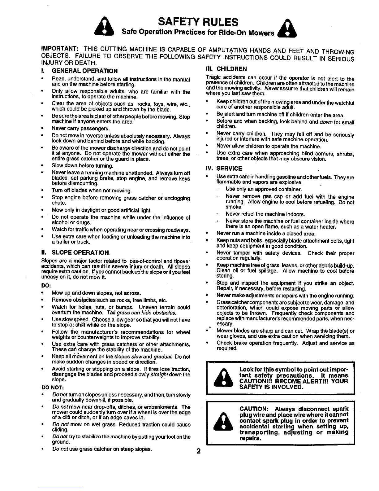
SAFETY RULES &
Safe Operation Practices for Ride-On Mowers
IMPORTANT: THIS CU'I-I'ING MACHINE IS CAPABLE
OBJECTS. FAILURE TO OBSERVE THE FOLLOWING
INJURY OR DEATH.
I. GENERAL OPERATION
• Read, understand, and follow all instructions in the manual
and on the machine before starting.
Only allow responsible adults, who are familiar with the
instructions, to operate the machine.
• Clear the area of ob ects such as rocks, toys, wire, etc.,
which could be p cked up and thrown by the b ads.
Be sure the area isclear ofotherpeople before mowing. Stop
machine if anyone enters the area.
• Never carry passengers.
• Do not mow inreverse unless absolutely necessary. Always
look down and behind before and while backing.
• Be aware ofthe mower discharge direction and do not point
it at anyone. Do not operate the mower without either the
entire grass catcher or the guard in place.
• Slow down before tuming.
• Never leave a running machine unattended. Always turn off
blades, set parking brake, stop engine, and remove keys
before dismounting,
• Turn off blades when not mowing.
Stop engine before removing grass catcher or unclogging
chute.
• Mow only in daylight or good adificial light.
• Do not operate the machine while under the influence of
alcohol or drugs.
• Watch for traffic when operating near or crossing roadways.
• Use extra care when loading or unloading the machine into
a trailer or truck.
II. SLOPE OPERATION
Slopesare ama orfactor related to loss-of-control andtipover
accidentswhichcan resultinsevereinjuryor death. Allslopes
requiraextracaution.Ifyoucannotbackuptheslopeor fyoufee
uneasyonit, do notmowit.
DO:
• Mow up add down slopes, not across.
• Remove obstacles such as rocks tree limbs, etc.
• Watch for holes, ruts, or bumps. Uneven terrain could
overturn the machine. Taftgrass can hide obstacles.
Use slow speed. Choose a low gear so that you willnot have
to stop,o_sh_ while on the slope.
• Follow the manufacturer's recommendations for wheel
weights or counterweights to improve stability.
• Use extra bare with grass catchers or other attachments.
These cab Change the stability ofthe machine.
Keep all movement on the slopes slowand gradual, Do not
make sudden changes in speed or direction.
• Avoid starting or stopping on a slope. If tires lose traction,
disengage the blades and proceed slowly straight down the
slope.
DO NOT:
• Donotturnonslopasunlessnecessary, andthen, tumslowly
and gradually downhill, if possible,
• Do not mow near drop-ode, ditches, or embankments. The
mower could suddenly turn over if a wheel is over the edge
of a cliff or ditch, or if an edge caves in.
Do not mow on wet grass. Reduced traction could cause
sliding.
Do not tryto stabilize the machine by puttingyour foot on the
ground.
• Do not use grass catcher on steep slopes.
OF AMPUTA.TING HANDS AND FEET AND THROWING
SAFETY INSTRUCTIONS COULD RESULT IN SERIOUS
IlL CHILDREN
Tragic accidents can occur if the operator is not alert to the
presenceofchildren,Childrenareoftenattractedtothemachine
and themowing activity. Neverassumethatchildrenwillremain
whereyoulast sawthem,
• Keepchildrenoutofthe mowingareaandunderthewatchful
careof another responsibleadult.
• Bealert andturn machineoffif childrenenterthearea.
Beforeand whenbacking,lookbehindand downfor small
children.
Never carrychildren. They may tall off and be seriously
injuredor interferewithsafe machineoperation.
• Neverallowchildrento operatethe machine.
• Use extra care when approaching blindcorners,shrubs,
trees,or otherobjectsthatmay obscurevision.
IV. SERVICE
• Use extra carein handling gasoline and other fuels. They are
flammable and vapors are explosive.
Use only an approved container.
Never remove gas cap or add fuel with the engine
running. Allow engine to eool before refueling. Do not
smoke.
Never refuel the machine indoors.
Never store the machine or fuel container inside where
there is an open flame, such as a water heater.
Never run a machine inside a closed area.
• Keep nutsand bolts, especially blade attachment botts, tight
and keep equipment in good condition.
Never tamper with safety devices. Check their proper
operation regulady,
• Keep machine free of grass, leaves, or other debds build-up.
Clean oil or fuel spillage. Allow machine to cool before
storing,
• Stop and inspect the equipment if you stdke an object.
Repair, if necessary, before mstading.
• Never make adjustments or repairs with the engine running.
• Grass catcher components ara sub ect towear, damage, and
deterioration, which could expose moving pads or allow
objects to be thrown. Frequently check components and
replace with manufacturer's recommended pads, when nec-
essary.
• * Mower blades are sharp and can cut. Wrap the blade(s) or
wear gloves, and use extra caution when servicing them.
• Check brake operation frequently. Adjust and service as
required.
i I I
Look for this symbol to point out impor-
tant safety precautions. It means
CAUTIONll! BECOME ALERTI!! YOUR
SAFETY IS INVOLVED,
i
{
CAUTION: Always disconnect spark
plug wire and place wire where it cannot
contact spark plug in order to prevent
acc dental starting when setting up,
transporting, adjusting or making
repairs,
2

CONGRATULATIONS on your purchase of a Sears
Tractor. It has been designed, en_.ineered and manufac-
tured to give you the best possible dependability and
performance.
Should you experience any problem you cannot easily
remedy, please contact your nearest Sears Authorized
Service Center/Department. We have competent, wel!-
trained technicians and the propertools to service or repair
this tractor.
Please read and retain this manual. The instructionswill
enable youtoassemble and maintain your tractor properly.
Always observe the =SAFETY RULES".
MODEL
NUMBER 944.609150
SERIAL
NUMBER
DATE OF PURCHASE
THE MODELAND SERIAL NUMBERSWlLL BE FOUND
ON A PLATE UNDER THE SEAT.
YOU SHOULD RECORD BOTH SERIAL NUMBER AND
DATE OF PURCHASE AND KEEP IN A SAFE PLACE
FOR FUTURE REFERENCE.
MAINTENANCE AGREEMENT
A Sears Maintenance Agreement isavailable on this prod-
uct. Contact your nearest Sears store for details.
CUSTOMER RESPONSIBILITIES
• Read and observe the safety rules.
Follow aregular schedule inmaintaining, caringfor and using
your tractor.
• Follow the instructions under =Customer Responsibilities"
and "Storage" sections of this owner's manual.
PRODUCT SPECIFICATIONS
HORSEPOWER: 15.5
GASOLINE CAPACITY 1.25 GALLONS
AND TYPE: UNLEADED REGULAR
b
OIL TYPE (API-SF/SG/SH): SAE 30 (above 32°F)
SAE5W-30 (below32°F)
OIL CAPACITY: W/FILTER: 3.5 PINTS
W/O FILTER: 3.0 PINTS
SPARKPLUG: CHAMPION RC12YC
(GAP:.040")
VALVE CLEARANCE:
, i
GROUND SPEED (MPH):
TIRE PRESSURE:
CHARGING SYSTEM:
INTAKE: .003 - .005"
EXHAUST:.005 - .007"
FORWARD: 0-5.5
REVERSE: 0-2.4
FRONT: 14 PSI
REAR: 10 PSI
9 AMPS @ 3600RPM
BATTERY: AMP/HR: 25
MIN. CCA: 190
CASE SIZE: U1R
BLADE BOLT TORQUE: 27-35 FT, LSS.
WARNING: This tractor is equipped with an internal
combustion engine and should not be used on or near any
unimproved forest-covered, brush-covered or grass-cov-
ered land unless the engine's exhaust system is equipped
with a spark arrester meeting applicable local or state laws
(ifany). If a spark arrester is used, it should be maintained
in effective working order by the operator.
A spark arrester for the muffler is available through your
nearest Sears Authorized Service Centre/Department (See
REPAIR PARTS section of this manual).
3
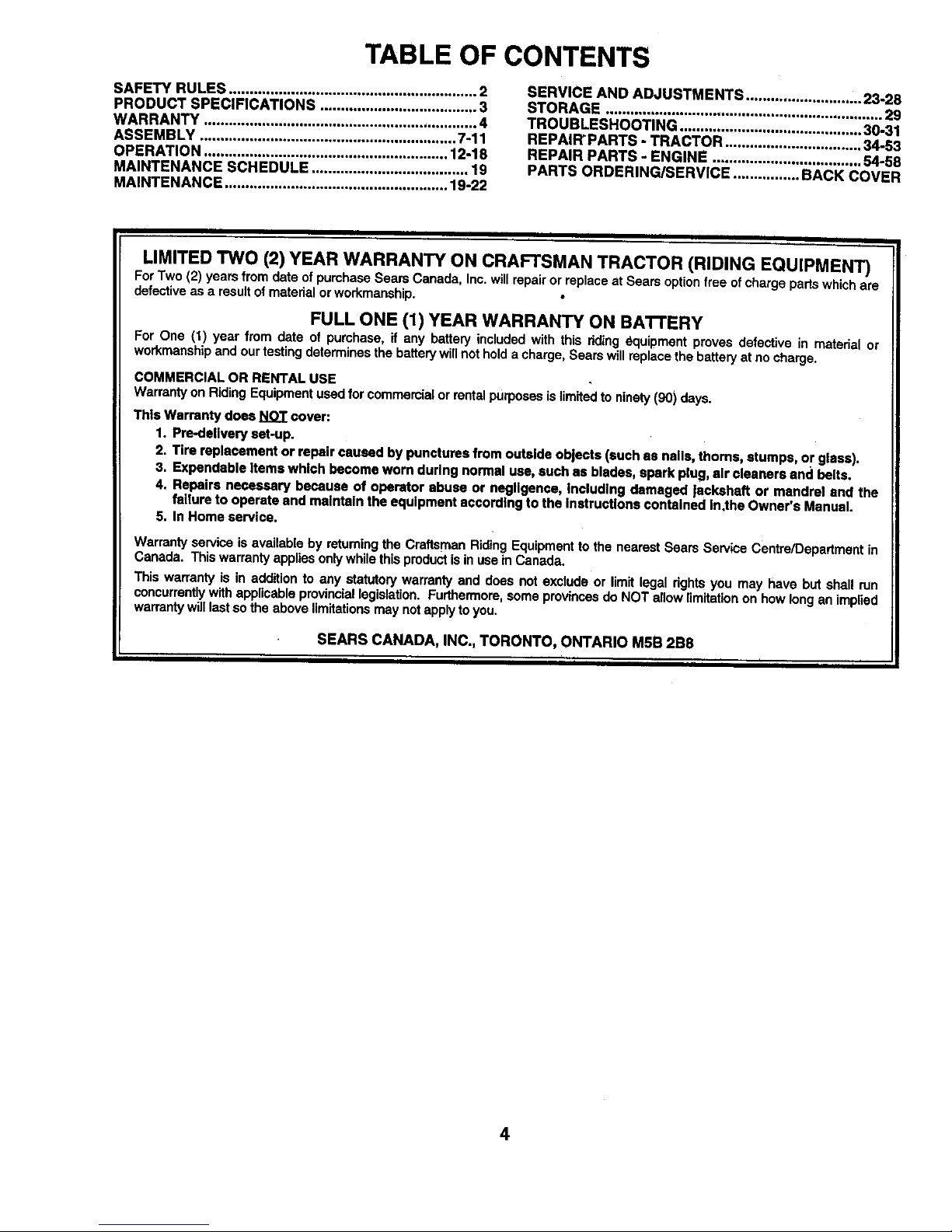
TABLE OF CONTENTS
SAFETY RULES ............................................................ 2
PRODUCT SPECIFICATIONS ...................................... 3
WARRANTY .................................................................. 4
ASSEMB LY .............................................................. 7-11
OPERATION ........................................................... 12-18
MAINTENANCE SCHEDULE ...................................... 19
MAINTENANCE ...................................................... 19-22
SERVICE AND ADJUSTMENTS ............................ 23-28
STORAGE ................................................................... 29
TROUBLESHOOTING ............................................ 30-31
REPAIR'PARTS - TRACTOR ................................. 34-53
REPAIR PARTS - ENGINE .................................... 54-58
PARTS ORDERING/SERVICE ................ BACK COVER
I I
LIMITED TWO (2) YEAR WARRANTY ON CRAFTSMAN TRACTOR (RIDING EQUIPMENT)
ForTwo (2) yearsfromdate of purchaseSearsCanada,Inc.willrepairorreplaceat Sears optionfree ofchargepartswhichare
defectiveasa resultofmaterialorworkmanship.
FULL ONE (1) YEAR WARRANTY ON BATrERY
For One (1) year from date of pumhase,if any battery includedwith this dding _quipment provesdefectivein materialor
workmanshipand ourtestingdeterminesthe batterywillnotholda charge,Searswillreplacethebatteryat nocharge.
COMMERCIAL OR RENTAL USE
Warrantyon RidingEquipmentusedfor commercialor rentalpurposesislimitedtoninety (90) days.
This Warranty does NOT cover:
1. Pre-dellveryset-up.
2. Tire replacement or repair caused by punctures from outside objects (such as nails, thoms, stumps, or glass).
3. Expendable Items which becomeworn during normal use, such as blades, spark plug,air cleaners and belts.
4. Repairs necessary because of operator abuse or negligence, Including damaged lackshaft or mandrel end the
failure to operate and maintain the equipment accordingto the Instructions contained In.the Owner's Manual.
5. In Home service.
Warranty serviceis evailabioby returning the CraftsmanR_ing Equipment tothe nearest SearsServiceCentre/Departmentin
Canada. Thiswarrantyappliesonlywhilethisproductisin useIn Canada.
Thiswarrantyis in additionto any statutorywarranty and does not excludeor limitlegal dghtsyou may have but shall run
concurrentlywithapplicable provirmiallegislation.Furthermore,someprovincesdo NOT e{!owlimitationon how longan impend
warrantywilllastso the abovelimitationsmaynotapplytoyou.
SEARS CANADA, INC., TORONTO, ONTARIO MsB 2B8
I I I I
4
I i
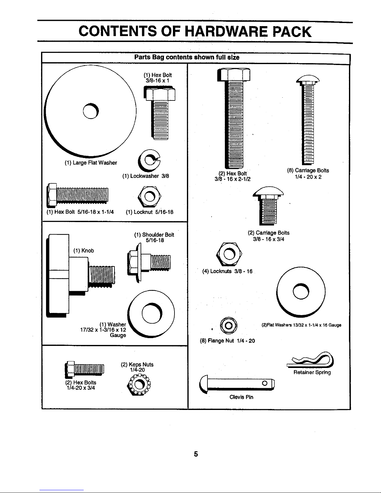
CONTENTS OF HARDWARE PACK
i II
i i i
Parts Bag contents shown full slie
I
(1) Large FlatWasher
(1) HexBolt
3/8-16 x 1
i
(1) Lockwasher_8
F---
ram"
(1) Hex Bolt 5/16-18 x 1-1/4
@
(1) Locknut 5/16-18
(1) ShoulderBolt
5/16-18
(1) Knob -_
l
(1) Washer I
17/32 x 1-3/16 x 12
Gauge
I_ (2) Keps Nuts
1/4-20
(2) Hex Bolts _%
1/4-20 x 314
m
n air
i..
(2) Hex Boff (8) Carriage Bolts
3/8 - 16 x 2-1/2 1/4 - 20 x 2
!
(2) CardageBolts
_8 - 16x 3/4
(4) Locknuts _8 - 16
@
(2)FlatWashers 13/32 x 1-1/4 x 16 Gauge
(8) FlangeNut 1/4- 20
I
Clevis Pin
op
Retainer Spring
5
i i i i i i i i
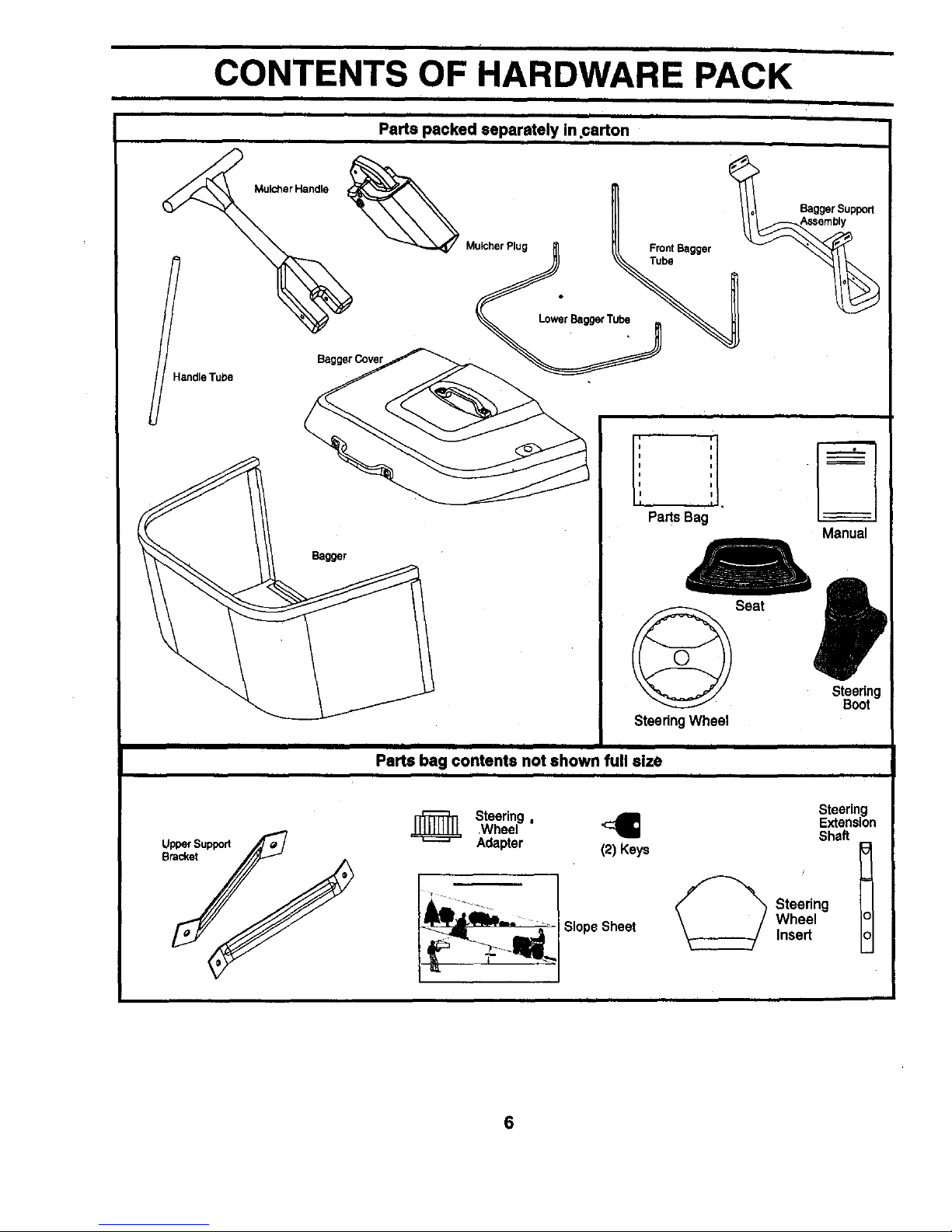
CONTENTS OF HARDWARE PACK
I i i i I I
I I i i iiii i i i I i i i
, , Parts packe d separately in.carton , ,
MulcherHandle
FrontBagger
Tube
eTube
_/BaggerSupport
Bag_r
i i i
L : -
PartsBag
Manual
PI
Steering
Boot
SteeringWheel
I I I II II I I I
Parts bag contents not shown full size
i i i i i
j_ Steering ,
Wheel <:_
Adapter (2) Keys
SlopeSheet
i
Steering
Extension
Shaft
Steering t
Wheel
Insert
6

ASSEMBLY
i i
Your new tractor has been assembled at the factory with exception of those parts left unasSembled for shipping purposes.
To ensure safe and proper operation of your tractor, all partsand hardware you assemble must be tightened securely. Use
the correct tools as necessary to insure proper tightness.
TOOLS REQUIRED FOR ASSEMBLY
A socket wrench set will make assembly easier. Standard
wrench sizes are listed.
(2) 9/16" wrenches (1) 3/8" socket with drive ratchet
(2) 7/16" wrenches Utility knife
(2) 1/2" wrenches Tire pressure gauge
When right and left hand is mentioned in this manual, it
means when you are in the operating position (seated
behind the steering wheel).
TO REMOVE TRACTOR FROM CARTON
UNPACK CARTON
• Remove all accessible loose parts and parts cartons
from carton (See page 5&6).
• Cut, from top to bottom, along lines on allfour comers
of carton, and lay panels flat.
• Check for any additional loose parts or cartons and
remove.
BEFORE ROLLING TRACTOR OFF SKID
A'FrACH STEERING WHEEL (See Fig. 1)
ASSEMBLE EXTENSION SHAFT AND BOOT
• Slide extension shaft onto lower steering shaft. Align
mounting holes in extension and lower shafts and
install 5/16 hex bolt and Iocknut. Tighten securely.
IMPORTANT: TIGHTEN BOLT AND NUT SECURELY TO
18-22 FT. LBS TORQUE.
• Place tabs of steering boot over tab slots in dash and
push down to secure.
INSTALL STEERING WHEEL
• Positionfront wheels of thetractor so they are pointing
straight forward.
• Slidesteeringwheeladapterontosteering shaftexten-
sion.
• Position steering wheel so cross bars are horizontal
(left to right) and slide inside boot and onto adapter.
• Assemble large flat washer, 3/8 lock washer, 318 hex
bolt and tighten securely,
• Snap steering wheel insert into center of steering
wheel.
• Remove protective materials from tractor hood and
grill.
IMPORTANT: CHECK FOR AND REMOVE ANY STAPLES
IN SKID THAT MAY PUNCTURE TIRES WHERE TRACTOR
IS TO ROLL OFF SKID.
F/INSERT
=_,,,_ - _. 3/8 HEX BOLT
_.._ 5/8 LOCK WASHER
(_ _ -- LARGE FLAT
"---- WASHER
STEERING _- \, ._, \\_
WHEEL , -_ _ J
STEERING
ADAPTER
FIG. 1
TO ROLL TRACTOR OFF SKID (See Opera-
tion section, page 13, for location and func-
tion of controls)
• Press liftlever plunger and raise attachment liftlever to
,itshighest position.
• Release parking brake by depressing clutch/brake
pedal.
• Place freewheel control in freewheelingposition to
disengage transmission (See 90 TRANSPORT" in
the Operation section of this manual).
• Roll tractor forward off skid.
• Remove banding holding discharge guard up against
tractor.
7
ii
ASSEMBLY
I
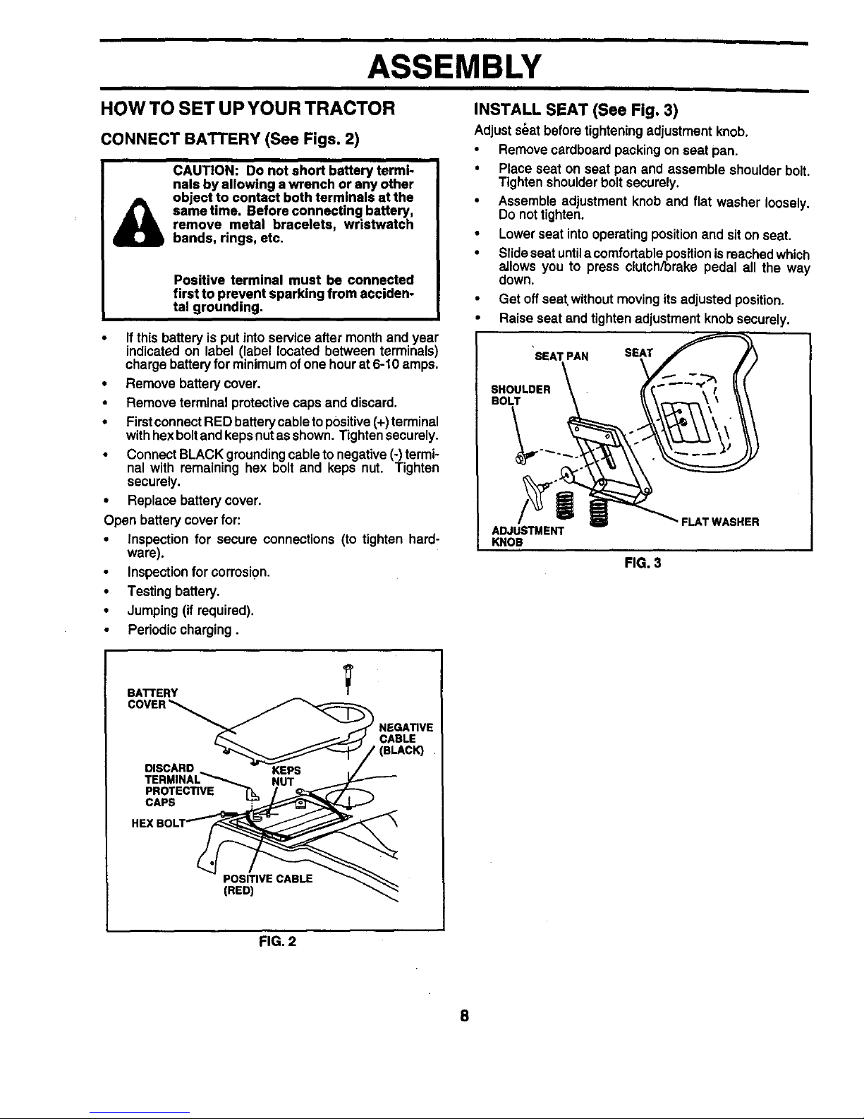
HOWTO SET UPYOUR TRACTOR
CONNECT BATTERY (See Figs. 2)
CAUTION: Do not short battery termi-
nals by allowing a wrench or any other
object to contact both terminals at the
same time, Before connecting battery,
remove metal bracelets, wristwatch
bands, rings, etc.
Positive terminal must be connected
first to prevent sparking from acciden-
tal grounding.
• Ifthis battery is put into service after month and year
indicated on label (label located between terminals)
charge battery for minimum of one hour at 6-10 amps.
• Remove battery cover.
• Remove terminal protective caps and discard.
• Firstconnect RED battery cable topositive (+)terminal
with hexboltand keps nut as shown. Tighten securely.
• Connect BLACK grounding cable to negative (-) termi-
nal with remaining hex bolt and keps nut. Tighten
securely.
• Replace battery cover.
Open battery cover for:
• Inspection for secure connections (to tighten hard-
ware).
• Inspection forcorrosi0n.
• Testing battery.
• Jumping (if required).
• Periodic charging.
INSTALL SEAT (SeeFig. 3)
Adjust s_at before tightening adjustment knob.
• Remove cardboard packing on seat pan.
• Place seat on seat pan and assemble shoulder bolt.
Tighten shoulder bolt securely.
• Assemble adjustment knob and flat washer loosely.
Do not tighten.
• Lower seat into operating position and sit on seat.
• Slideseat untila comfortable positionis reached which
allows you to press clutch/brake pedal all the way
down.
• Get off seat without moving its adjusted position.
• Raise seat and tighten adjustment knob securely.
'SEAT PAN SEAT
SHOULDER
BOLT
ADJUSTMENT
KNOB
FIG. 3
- FLAT WASHER
BATrERY
V
DISCARD
TERMINAL_
PROTEC_VE TU.
CAPS "I"
NUT
CABLE
(BLAC_
PosmvE CABLE
(RED)
FIG. 2
8
ASSEMBLY
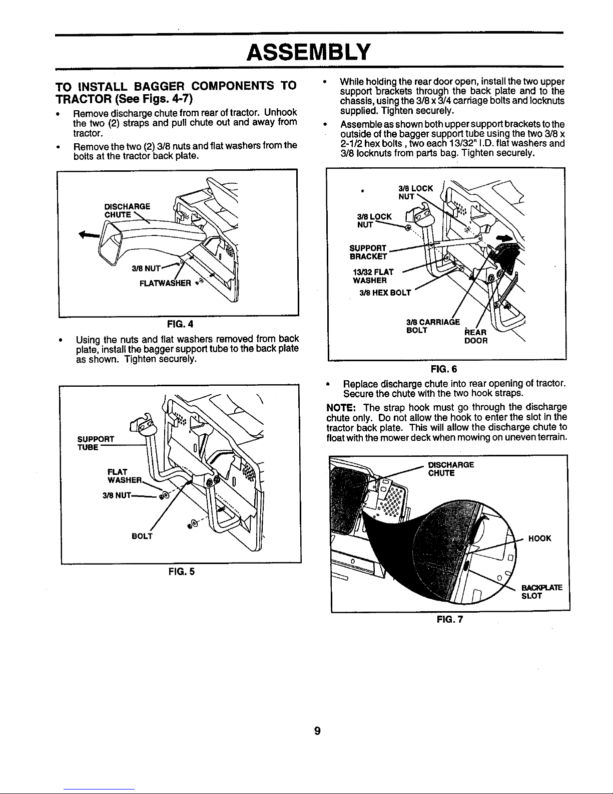
TO INSTALL BAGGER COMPONENTS TO
TRACTOR (See Figs. 4-7)
• Remove discharge chute from rear of tractor. Unhook
the two (2) straps and pull chute out and away from
tractor.
• Remove the two (2) 3/8 nuts and flat washers from the
bolts at the tractor back plate.
While holdingthe rear door open, install the two upper
support brackets through the back plate and to the
chassis, using the 3/8 x 3/4 carriage bolts and Iocknuts
supplied. Tighten securely.
Assemble as shown both upper support brackets to the
outside of the bagger support tube using the two 3/8 x
2-112 hex bolts, two each 13/32" I.D. flat washers and
3/8 Iocknuts from parts bag. Tighten securely.
DISCHARGE
FIG. 4
Using the nuts and flat washers removed from back
plate, installthe bagger supporttube to the back plate
as shown. Tighten securely.
\
SUPPORT
TUBE
FLAT
WASHER
BOLT
FIG. 5
3/8 LOCK
3/8L
SUPPORT
BRACKET
13/32 FLAT
WASHER
3/8HEXBOLT
3/SCARRIAGE
BOLT hEAR
DOOR
FIG. 6
• Replace discharge chute into rear opening of tractor.
Secure the chute with the two hook straps.
NOTE: The strap hook must go through the discharge
chute only. Do not allow the hook to enter the slot in the
tractor back plate. This will allow the discharge chute to
float with the mower deck when mowing on uneven terrain.
DISCHARGE
CHUTE
HOOK
BACKPLAIE
SLOT
FIG. 7
9
ASSEMBLY
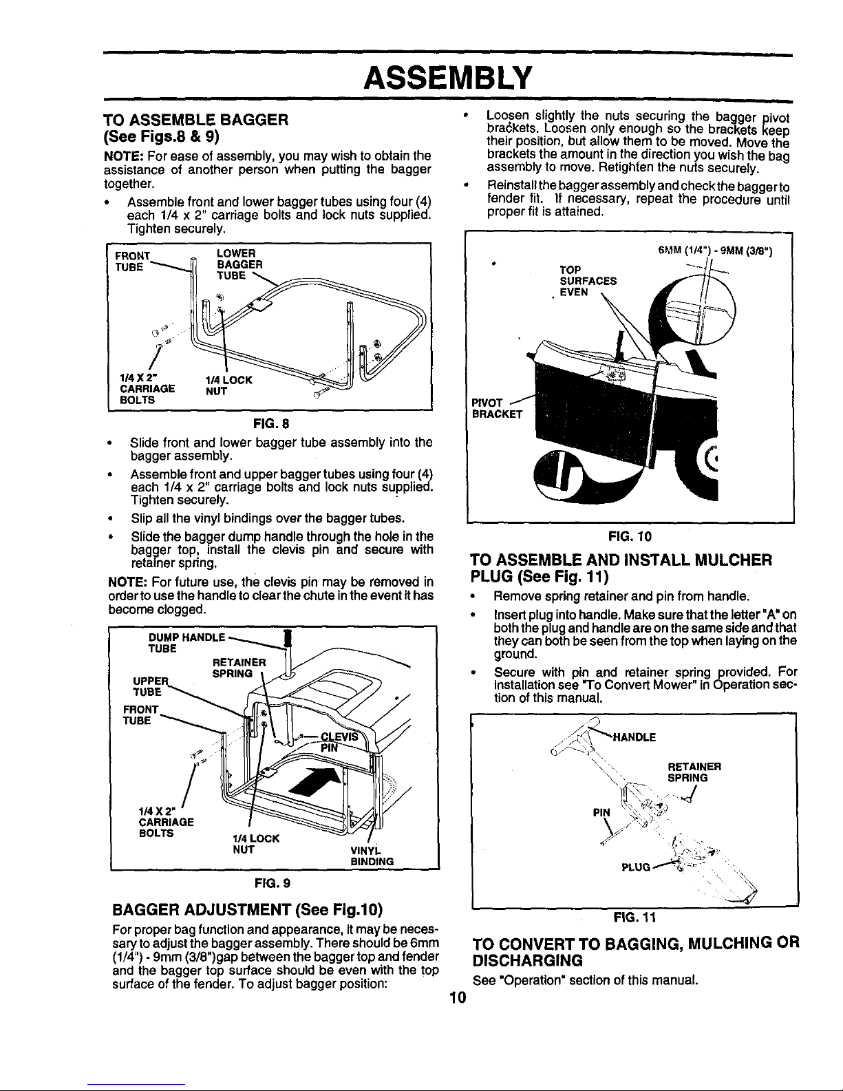
TO ASSEMBLE BAGGER
(See Figs.8 & 9)
NOTE: For ease of assembly, you may wish to obtain the
assistance of another person when putting the bagger
together.
• Assemble front and lower bagger tubes using four (4)
each 1/4 x 2" carriage bolts and lock nuts supplied.
Tighten securely.
FRONT LOWER
TUBE BAGGER
TUBE
1/4 X 2" 1/4 LOCK
CARRIAGE NUT
BOLTS
FIG. 8
• Slide front and lower bagger tube assembly into the
bagger assembly.
• Assemble front and upper bagger tubes using four (4)
each 1/4 x 2" carriage bolts and lock nuts supplied.
Tighten securely.
• Slip all the vinyl bindings over the bagger tubes.
• Slide the bagger dump handle through the hole in the
bagger top_ install the clevis pin and secure with
retainer spnng.
NOTE: For future use, the clevis pin may be removed in
order to use the handle toclear the chute inthe event ithas
become clogged.
TUBE
TUBE
RETAINER
1_X2 _
CARRIAGE
BOLTS
1_ LOCK
NUT
FIG. 9
VINYL
BINDING
Loosen slightly the nuts securing the bagger pivot
brackets. Loosen only enough so the brackets keep
their position, but allow them to be moved. Move the
brackets the amount in the direction you wish the bag
assembly to move. Retigh{en the nuts securely.
Reinstall the bagger assembly and check the baggerto
fender fit. If necessary, repeat the procedure until
proper fit is attained.
TOP
SURFACES
• EVEN
SMM (114")- 9MM (3/8")
PIVOT
BRACKET
FIG. 10
TO ASSEMBLE AND INSTALL MULCHER
PLUG (See Fig. 11)
• Remove spring retainer and pin from handle.
• Insert plug into handle. Make surethat the letter"A' on
boththe plug and handle are on the same side and that
they can both be seen fromthe top when laying on the
ground.
• Secure with pin and retainer spring provided. For
installationsee "ToConvert Mower" in Operation sec-
tion of this manual.
\ _ RETAINER
_ SPRING
'4
BAGGER ADJUSTMENT (See Fig.10)
For proper bag functionand appearance, it may be neces-
sary to adjust the bagger assembly. There should be 6ram
(1/4") - 9ram (3/8")gap between the bagger top and fender
and the bagger top surface should be even with the top
surface of the fender. To adjust bagger position:
10
FIG. 11
TO CONVERT TO BAGGING, MULCHING OR
DISCHARGING
See "Operation" section of this manual.
ASSEMBLY
I I
/ CHECKLIST
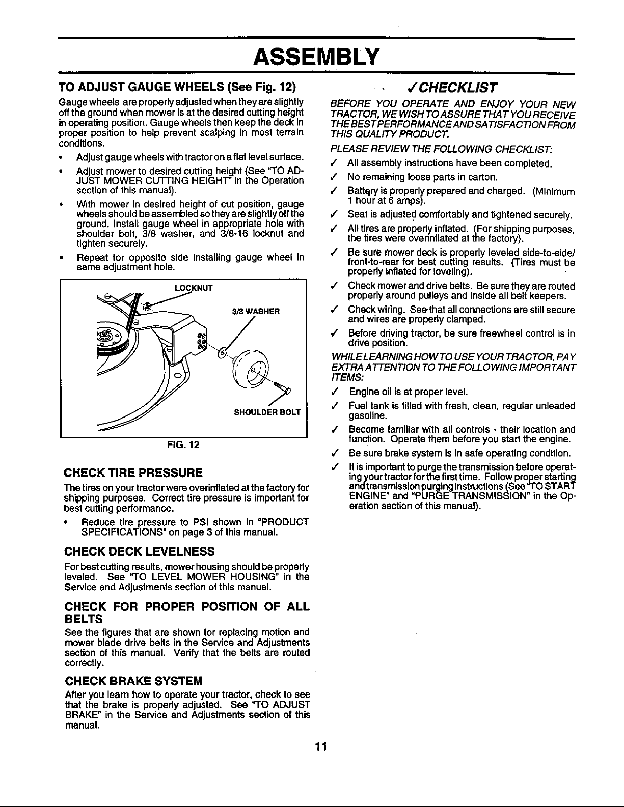
TO ADJUST GAUGE WHEELS (See Fig. 12)
Gauge wheels are properly adjustedwhen they are slightly
off the ground when mower is at the desired cutting height
inoperating position. Gauge wheels then keep the deck in
proper position to help prevent scalping in most terrain
conditions.
• Adjust gauge wheels withtractor on a flat level surface.
• Adjust mower to desired cutting height (See "TO AD-
JUST MOWER CUTTING HEIGHT' in the Operation
section of this manual).
• With mower in desired height of cut position, gauge
wheels should be assembled so they are slightly off the
ground. Install gauge wheel in appropriate hole with
shoulder bolt, 3/8 washer, and 3/8-16 Iocknut and
tighten securely.
• Repeat for opposite side installing gauge wheel in
same adjustment hole.
BEFORE YOU OPERATE AND ENJOY YOUR NEW
TRACTOR, WE WISH TOASSURE THAT YOU RECEIVE
THE BEST PERFORMANCE AND SATISFACTION FROM
THIS QUALITY PRODUCT.
PLEASE REVIEW THE FOLLOWING CHECKLIST:
,/ All assembly instructionshave been completed.
/ No remaining loose parts in carton.
,/ Batteryis properly prepared and charged. (Minimum
1 hour at 6 amps).
•/ Seat is adjusted comfortably and tightened securely.
/ Alltires are propedy inflated. (For shipping purposes,
the tires were ovednflated at the factory).
,/ Be sure mower deck is properly leveled side-to-side/
front-to-rear for best cutting results. (Tires must be
properly inflated for leveling).
LOCKNUT / Check mower and drive belts. Be sure they are routed
o__ properly around pulleys and inside all belt keepers.
3/8 WASHER /
/
/
/
SHOULDER BOLT
Check wiring. See that all connections are still secure
and wires are properly clamped.
Before driving tractor, be sure freewheel control is in
drive position.
WHILE LEARNING HOW TO USE YOUR TRACTOR, PAY
EXTRA ATTENTION TO THE FOLLOWING IMPORTANT
ITEMS:
FIG. 12
CHECK TIRE PRESSURE
The tires on yourtractor were overinflated at the factory for
shipping purposes. Correct tire pressure is important for
best cutting performance.
• Reduce tire pressure to PSI shown in =PRODUCT
SPECIFICATIONS" on page 3 of this manual.
,,I
,/
Engine oil is at proper level.
Fuel tank is filled with fresh, clean, regular unleaded
gasoline.
Become familiar with all controls - their location and
function. Operate them before you start the engine.
Be sure brake system is in safe operating condition.
Itis Important to purge the transmission before operat-
ingyour tractor for the firsttime. Follow proper starting
andtransmission purging instructions(See"TO START
ENGINE" and =PURGE TRANSMISSION" in the Op-
eration section of this manual).
CHECK DECK LEVELNESS
For bestcutting results,mower housingshould be properly
leveled. See "TO LEVEL MOWER HOUSING" in the
Service and Adjustments section of this manual.
CHECK FOR PROPER POSITION OF ALL
BELTS
see the figures that are shown for replacing motion and
mower blade drive belts in the Service and Adjustments
section of this manual. Verify that the belts are routed
correctly.
CHECK BRAKE SYSTEM
After you learn how to operate your tractor, check to see
that the brake is properly adjusted. See "TO ADJUST
BRAKE" in the Service and Adjustments section of this
manual.
11
OPERATION
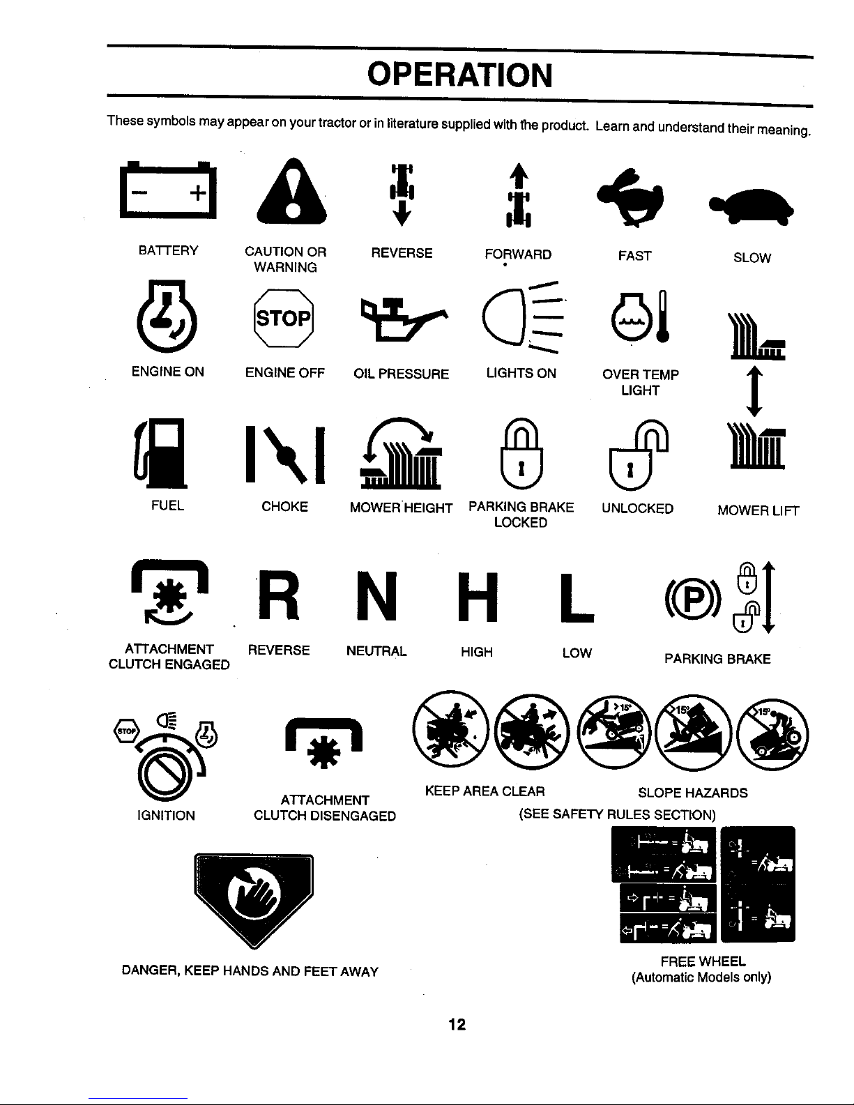
These symbols may appear on your tractor or in literature supplied with the product. Learn and understand their meaning.
BA'I-I'ERY CAUTION OR REVERSE FORWARD FAST SLOW
WARNING
ENGINE ON ENGINE OFF OIL PRESSURE LIGHTS ON OVER TEMP "_
LIGHT
L
FUEL CHOKE MOWERHEIGHT PARKING BRAKE UNLOCKED
LOCKED
MOWER LIFT
N H L
ATTACHMENT REVERSE NEUTRAL HIGH LOW
CLUTCH ENGAGED
IGNITION
A'N'ACHM ENT
CLUTCH DISENGAGED
PARKING BRAKE
KEEP AREA CLEAR SLOPE HAZARDS
(SEE SAFETY RULES SECTION)
DANGER, KEEP HANDS AND FEET AWAY
FREE WHEEL
(Automatic Models only)
12
i i
OPERATION
KNOW YOUR TRACTOR
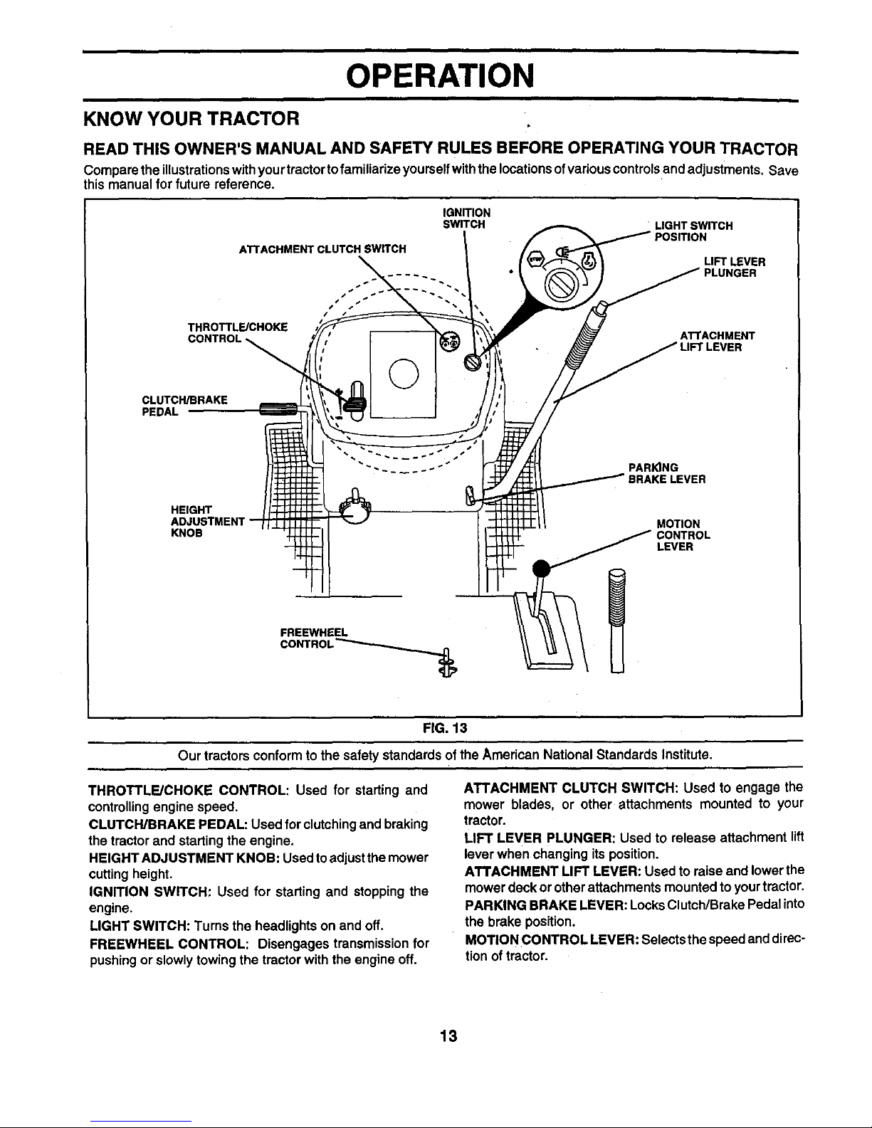
READ THIS OWNER'S MANUAL AND SAFETY RULES BEFORE OPERATING YOUR TRACTOR
Compare the illustrationswith yourtractorto familiarize yourself withthe locations ofvarious controls and adjustments. Save
this manual for future reference.
IGNITION
SWITCH
ATTACHMENT CLUTCH SWITCH
THROTTLE/CHOKE
LIGHT SWITCH
LIFT LEVER
PLUNGER
ATTACHMENT
CLUTCH/BRAKE
PEDAL
©
PARKING
E LEVER
HEIGHT
ADJUSTMENT
KNOB
MOTION
CONTROL
LEVER
FREEWHEEL
FIG. 13
Our tractors conform to the safety standards of the American National Standards Institute.
THROTTLE/CHOKE CONTROL: Used for starting and
controllingengine speed.
CLUTCWBRAKE PEDAL: Used for clutchingand braking
the tractor and starting the engine.
HEIGHT ADJUSTMENT KNOB: Used toadjust the mower
cutting height.
IGNITION SWITCH: Used for starting and stopping the
engine.
LIGHT SWITCH: Turns the headlights on and off.
FREEWHEEL CONTROL: Disengages transmission for
pushing or slowly towing the tractor with the engine off.
ATTACHMENT CLUTCH SWITCH: Used to engage the
mower blades, or other attachments mounted to your
tractor.
LIFT LEVER PLUNGER: Used to release attachment lift
lever when changing its position.
ATTACHMENT LIFT LEVER: Used to raise and lower the
mower deck or other attachments mounted to your tractor.
PARKING BRAKE LEVER: Locks Clutch/Brake Pedal into
the brake position.
MOTION CONTROL LEVER: Selects the speed and direc-
tion of tractor.
13
i
OPERATION
i
The operation of any tractor can result if=foreign objects thrown into the eyes, which
can result In severe eye damage. Always wear safety glasses or eye shields while
operating your tractor or performing any adjustments or repairs. We recommend a
wide vision safety mask over spectacles or standard safety glasses.
HOW TO USE YOUR TRACTOR
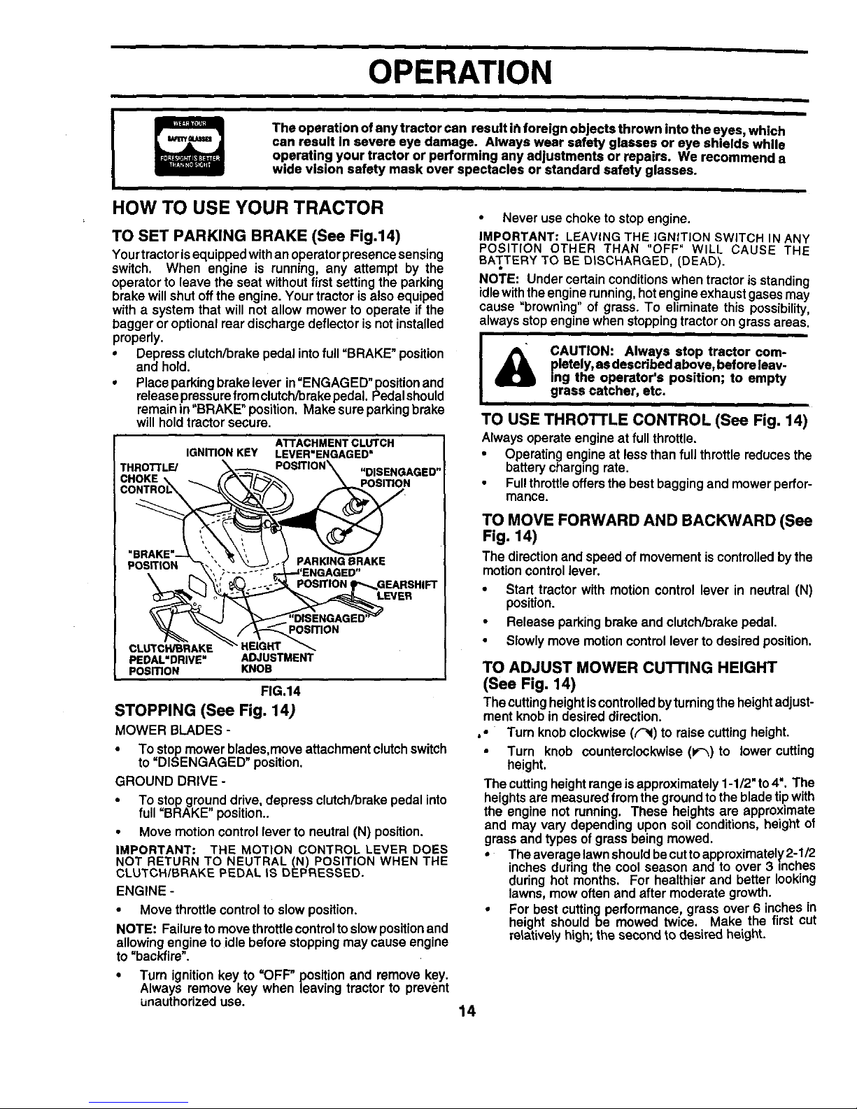
TO SET PARKING BRAKE (See Fig.14)
Yourtractor isequipped with an operator presence sensing
switch. When engine is running, any attempt by the
operator to leave the seat without first setting the parking
brake willshut offthe engine. Your tractor is also equiped
with a system that will not allow mower to operate if the
bagger or optional rear discharge deflector is not installed
properly.
• Depress clutch/brake pedal into full=BRAKE" position
and hold.
• Place perking brake lever in"ENGAG ED" positionand
release pressure from clutch/brake pedal. Pedalshoukf
remain in "BRAKE" position. Make sure parking brake
will hold tractor secure.
THROTrLE/
FIG.14
STOPPING (See Fig, 14)
MOWER BLADES -
• To stop mower blades,move attachment clutch switch
to "DISENGAGED" position,
GROUND DRIVE -
• To stop ground drive, depress clutch/brake pedal into
full =BRAKE" position..
• Move motion control lever to neutral (N) position.
IMPORTANT: THE MOTION CONTROL LEVER DOES
NOT RETURN TO NEUTRAL (N) POSITION WHEN THE
CLUTCH/BRAKE PEDAL IS DEPRESSED.
ENGINE -
• Move throttle control to slow position.
NOTE: Failure to move throttle controltoslow positionand
allowing engine to idle before stopping may cause engine
to "backfire".
• Turn ignition key to =OFF" position and remove key.
Always remove key when leaving tractor to prevent
unauthorized use.
• Never use choke to stop engine.
IMPORTANT: LEAVING THE IGNITION SWITCH IN ANY
POSITION OTHER THAN "OFF" WILL CAUSE THE
BATTERY TO BE DISCHARGED, (DEAD).
NOTE: Under certain conditions when tractor is standing
idle with the engine running, hot engine exhaust gases may
cause "browning" of grass. To eliminate this possibility,
always stop engine when stopping tractor on grass areas.
LOU_SE CAUTION: Always stop tractor com-
pletely, as described above, before leav-
ing the operator's position; to empty
grass catcher, etc.
THROTTLE CONTROL (See Fig. 14)
Always operate engine at full throttle.
• Operating engine at lessthan full throttle reduces the
battery charging rate.
• Full throttle offers the best bagging and mower perfor-
mance.
TO MOVE FORWARD AND BACKWARD (See
Fig. 14)
The directionand speedofmovementis controlledbythe
motioncontrollever.
• Start tractor with motion control lever in neutral (N)
position.
• Release parking brake and clutch/brake pedal.
• Slowly move motion control lever to desired position.
TO ADJUST MOWER cu'rrlNG HEIGHT
(See Fig. 14)
The cuttingheight is controlled byturning the height adjust-
ment knob in desired direction.
,. Turn knob clockwise (F,i) to raise cutting height.
• Turn knob counterclockwise (P-_) to lower cutting
height.
The cuttingheight range is approximately 1-1/2" to4". The
heights are measured from the ground to the bladetip with
the engine not running. These heights are approximate
and may vary depending upon soil conditions, height of
grass and types of grass being mowed.
• The average lawn shoukf becut to approximately 2-1/2
inches during the cool season and to over 3 inches
during hot months. For healthier and better looking
lawns, mow often and after moderate growth.
• For best cutting performance, grass over 6 inches in
height should be mowed twice. Make the first cut
relatively high; the second to desired height.
14
OPERATION
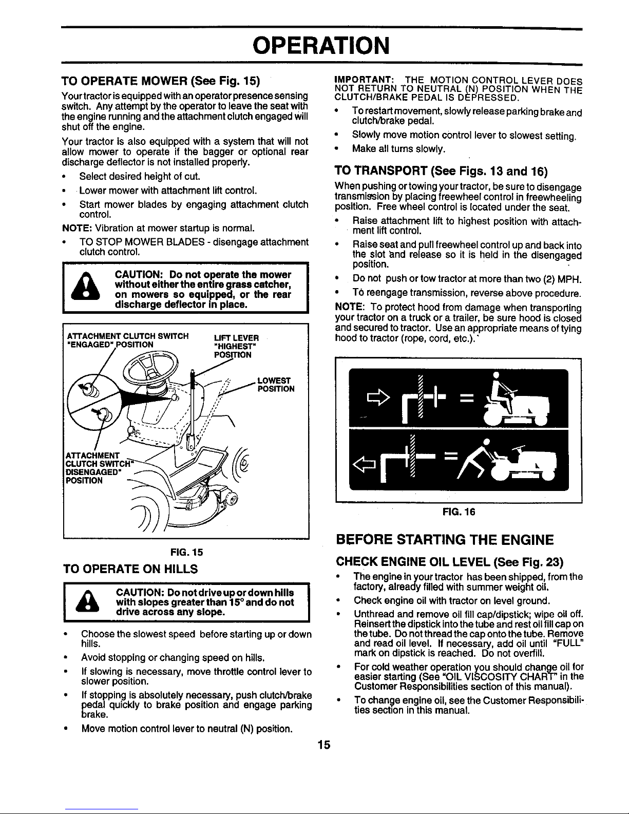
TO OPERATE MOWER (See Fig. 15)
Yourtractor isequipped with an operator presence sensing
switch. Any attempt by the operator to leave the seat with
the engine running and the attachment clutch engaged will
shut off the engine.
Your tractor is also equipped with a system that will not
allow mower to operate if the bagger or optional rear
discharge deflector is not installed properly.
• Select desired height of cut.
• Lower mower with attachment lift control.
• Start mower blades by engaging attachment clutch
control.
NOTE: Vibration at mower startup is normal.
• TO STOP MOWER BLADES - disengage attachment
clutch control.
I
CAUTION: Do not operate the mower I
without either the entire grass catcher,
I
on mowers so equipped, or the rear
discharge deflector in place.
LIFT LEVER
"HIGHEST"
PosmoN
LOWEST
7/
ATTACHMENT
DISENGAGED"
POSITION
IMPORTANT: THE MOTION CONTROL LEVER DOES
NOT RETURN TO NEUTRAL (N) POSITION WHEN THE
CLUTCH/BRAKE PEDAL IS DEPRESSED.
• To restart movement, slowlyrelease parking brake and
clutch/brake pedal.
• Slowly move motion control lever to slowest setting.
• Make all turns slowly.
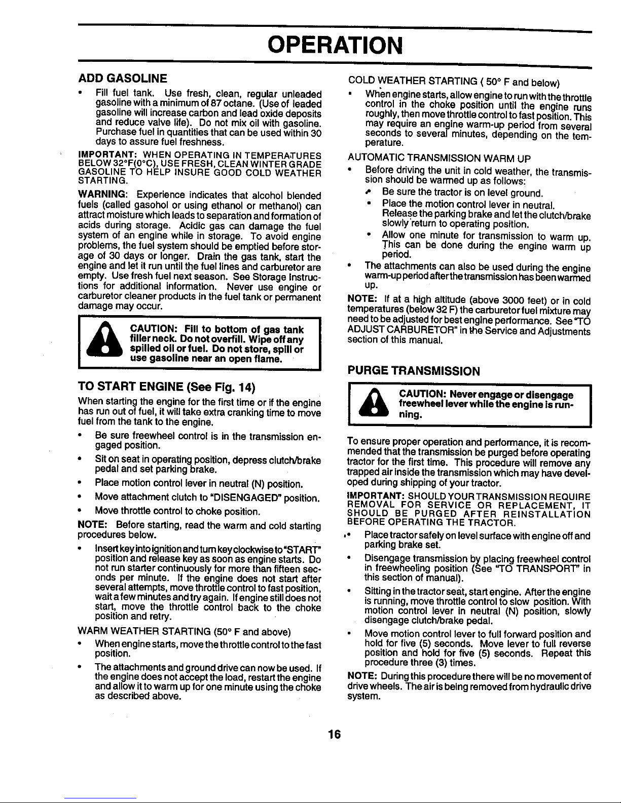
TO TRANSPORT (See Figs. 13 and 16)
When pushingortowing your tractor, be sure to disengage
transmission by placing freewheel control in freewheeling
position. Free wheel control is located under the seat.
• Raise attachment liftto highest position with attach-
ment liftcontrol.
• Raise seat and pull freewheel control up and back into
the slot and release so it is held in the disengaged
position.
• Do not push or tow tractor at more than two (2) MPH.
• TO reengage transmission, reverse above procedure.
NOTE: To protect hood from damage when transporting
your tractor on a truck or a trailer, be sure hood is closed
and secured to tractor. Use an appropriate means oftying
hood to tractor (rope, cord, etc.)."
FIG. 16
FIG. 15
TO OPERATE ON HILLS
I _, CAUTION: Donotdriveupordownhllls I
with slopes greater than 15° and do not
drive across any slope.
• Choose the slowest speed before starting up or down
hills.
• Avoid stopping or changing speed on hills.
• If slowing is necessary, move throttle control lever to
slower position.
• If stopping is absolutely necessary, push clutch/brake
pedal quickly to brake position and engage parking
brake.
• Move motion control lever to neutral (N) position.
BEFORE STARTING THE ENGINE
CHECK ENGINE OIL LEVEL (See Fig. 23)
• The engine in your tractor has been shipped, from the
factory, already filled with summer weight oil.
• Check engine oil with tractor on level ground.
• Unthread and remove oil fill cap/dipstick; wipe oil off.
Reinsert the dipstick intothe tube and rest oilfill cap on
the tube. Do not thread the cap onto the tube. Remove
and read oil level. If necessary, add oil until "FULL"
mark on dipstick is reached. Do not overfill.
• For cold weather operation you should change oil for
easier starting (See OIL VISCOSITY CHART" in the
Customer Responsibilities section of this manual).
• To change engine oil, see the Customer Responsibili-
ties section in this manual.
15
OPERATION
ADD GASOLINE
• Fil! fuel tank. Use fresh, clean, regular unleaded
gasoline with a minimum of87 octane. (Use of leaded
gasoline will increase carbon and lead oxide deposits
and reduce valve life). Do not mix oil with gasoline.
Purchase fuel in quantities that can be used within 30
days to assure fuel freshness.
IMPORTANT: WHEN OPERATING IN TEMPERA,TURES
BELOW 32°F(0°C), USE FRESH, CLEAN WINTER GRADE
GASOLINE TO HELP INSURE GOOD COLD WEATHER
STARTING.
WARNING: Experience indicates that alcohol blended
fuels (called gasohol or using ethanol or methanol) can
attract moisture which leads to separation and formation of
acids during storage. Acidic gas can damage the fuel
system of an engine while in storage. To avoid engine
problems, the fuel system should be emptied before stor-
age of 30 days or longer. Drain the gas tank, start the
engine and let it run until the fuel lines and carburetor are
empty. Use fresh fuel next season. See Storage Instruc-
tions for additional information. Never use engine or
carburetor cleaner products in the fuel tank or permanent
damage may occur.
CAUTION: Fill to bottom of gas tank
filler neck. Do not overfill. Wipe off any
spilled oil or fuel. Do not store, spill or
use gasoline near an open flame.
TO START ENGINE (See Fig. 14)
When starting the engine for the first time or if the engine
has runout of fuel, itwilltake extra cranking time to move
fuel from the tank to the engine.
• Be sure freewheel control is in the transmission en-
gaged position.
• Siton seat inoperating position, depress clutch/brake
pedal and set parking brake.
• Place motion control lever in neutral (N) position.
• Move attachment clutch to =DISENGAGED" position.
• Move throttle control to choke position.
NOTE: Before starting, read the warm and cold starting
procedures below.
• Insertkeyinto ignitionandtum keyclockwiseto "START"
positionand release key as soon as engine starts. Do
not run starter continuously for more than fifteen sec-
onds per minute. If the engine does not start after
several attempts, move throttle control tofast position,
wait a few minutes and try again. Ifengine stilldoes not
start, move the throttle control back to the choke
position and retry.
WARM WEATHER STARTING (50 ° F and above)
• When engine starts, move the throttle controlto the fast
position.
• The attachments and ground drivecan now be used. If
the engine does not accept the load, restart the engine
and allow itto warm up for one minute using the choke
as described above.
COLD WEATHER STARTING ( 50° F and below)
• When enginestarts, allow engine to runwith the throttle
control in the choke position until the engine runs
roughly,then movethrottle controlto fast position.This
may require an engine warm-up period from several
seconds to several minutes, depending on the tem-
perature.
AUTOMATIC TRANSMISSION WARM UP
• Before driving the unit in cold weather, the transmis-
sion should be warmed up as follows:
•- Be sure the tractor is on level ground.
• Place the motion control lever in neutral.
Release the parking brake and let the clutch/brake
slowly'return to operating position.
• Allow one minute for transmission to warm up.
This can be done during the engine warm up
period.
• The attachments can also be used during the engine
warm-up pedod after thetransmission has been warmed
up.
NOTE: If at a high altitude (above 3000 feet) or in cold
temperatures (below 32 F) the carburetor fuel mixture may
need to be adjusted for best engine performance. See "TO
ADJUST CARBURETOR" in the Service and Adjustments
section of this manual.
PURGE TRANSMISSION
I _ CAUTION: Neverengageordisengage
freewheel lever while the engine is run-
ning.
To ensure proper operation and performance, it is recom-
mended that the transmission be purged before operating
tractor for the first time. This procedure will remove any
trapped air inside the transmission which may have devel-
oped dudng shipping ofyour tractor.
IMPORTANT: SHOULD YOURTRANSMISSION REQUIRE
REMOVAL FOR SERVICE OR REPLACEMENT, IT
SHOULD BE PURGED AFTER REINSTALLATION
BEFORE OPERATING THE TRACTOR.
," Place tractorsafely on level surface with engine offand
parking brake set.
• Disengage transmission by placing freewheel control
in freewheeling position (See "TO TRANSPORT" in
this section of manual).
• Sitting inthe tractorseat start engine. After the engine
is running, move throttlecontrolto slow position.With
motion control lever in neutral (N) position, slowly
disengage clutch/brake pedal.
• Move motion control lever to full forward position and
hold for five (5) seconds. Move lever to full reverse
position and hold for five (5) seconds. Repeat this
procedure three (3) times.
NOTE: During this procedure there willbe no movement of
drivewheels. The air isbeing removed from hydraulicdrive
system.
16
I
OPERATION
• Move motioncontrollever toneutral (N) position. Shut-
off engine and set parking brake.
• Engage transmission by placing freewheel control in
driving position (See "TO TRANSPORT" inthis section
of manual).
• Sittinginthetractor seat, startengine. Afterthe engine
is running, move throttle control to half (1/2) speed.
With motioncontrol lever in neutral (N) position, slowly
disengage clutch/brake pedal.
• Slowly move motion control lever forward, after the
tractor moves approximately five (5) feet, slowly move
motion control lever to reverse position. After the
tractor moves approximately five (5) feet retum the
motion control lever tothe neutral(N) position. Repeat
this procedure with the motion control lever three (3)
times.
Your tractor is now purged and now ready for normal
operation.
MOWING TIPS
• Tire chains cannot be used when the mower housing
is attached to tractor.
• Mower should be properly leveled for best mowing
performance. See "TO LEVEL MOWER HOUSING" in
the Service and Adjustments section ofthis manual.
• The left hand side of mower should be used for trim-
ming.
• If grass is extremely tall, it should be mowed twice to
reduce load and possible fire hazard from dded clip-
pings. Make first cut relatively high; the second to the
desired height.
• Do not mow grass when it is wet. Wet grass will plug
mower and leave undesirable clumps. Allow grass to
dry before mowing.
• Always operate engine at fullthrottle when mowing to
assure better mowing performance and proper dis-
charge of material. Regulate ground speed by select-
ing a low enough gear to give the mower cutting
performance as well as the quality of cut desired.
• When operating attachments, select a ground speed
that will suit the terrain and give best performance of
the attachment being used.
MULCHING MOWING TIPS
IMPORTANT: FOR BEST PERFORMANCE, KEEP
MOWER HOUSING FREE OF BUILT-UP GRASS AND
TRASH. CLEAN AFTER EACH USE,
The special mulching blade will recut the grass clip-
pings many times and reduce them in size so that as
they fall ontothe lawn they will disperse into the grass
and not be noticed. Also,. the mulched grass will
biodegrade quickly to provide nutrients for the lawn.
Always mulch with your highest engine (blade) speed
as this will provide the best recutting action of the
blades.
• Avoid cuttingyourlawn when it is wet. Wet grass tends
to form clumps and interferes with the mulching action.
The best time to mow your lawn is the early afternoon.
At this time the grass has dried and the newly cut area
will not be exposed to the direct sun.
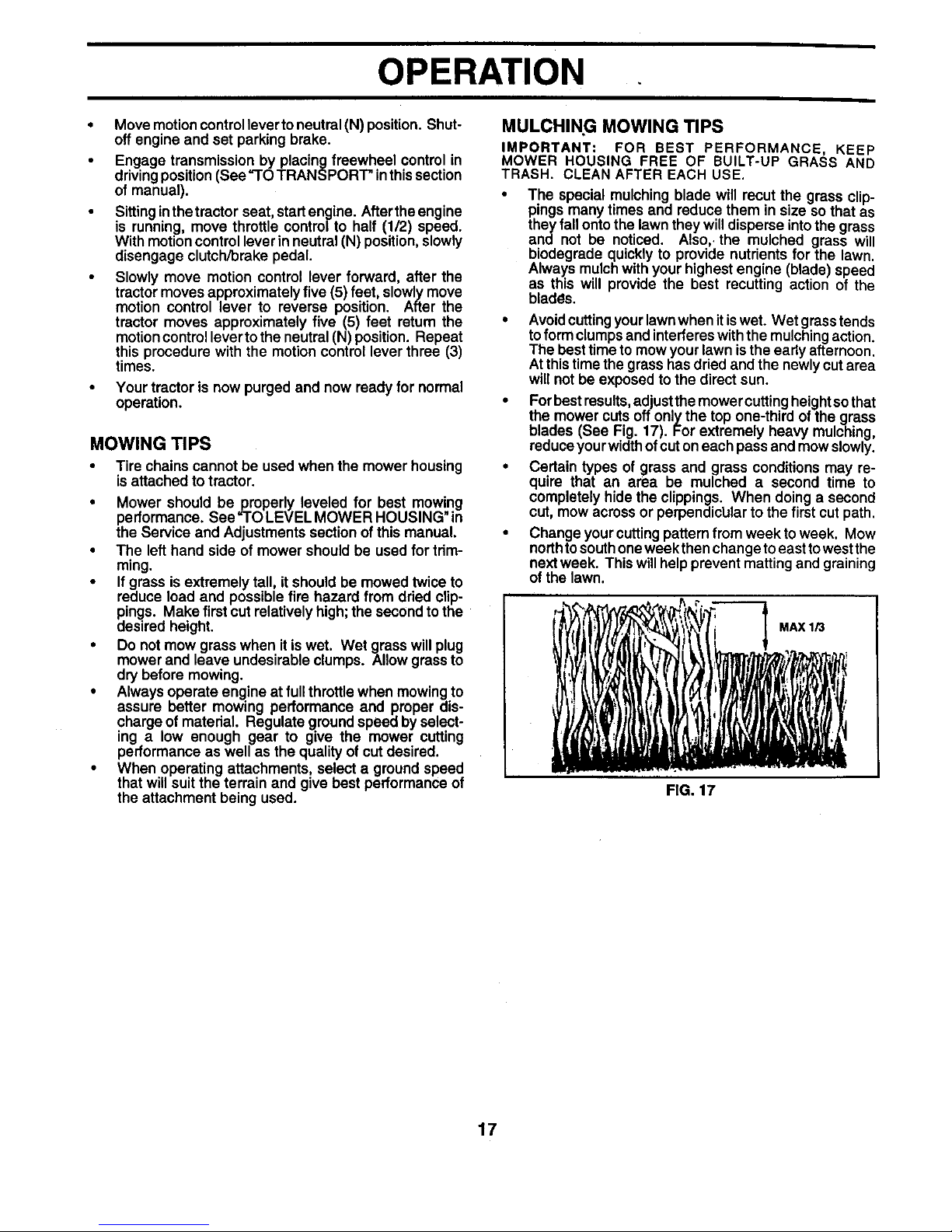
• For best results, adjust the mower cutting height so that
the mower cuts off only the top one-third of the grass
blades (See Fig. 17). For extremely heavy mulching,
reduce your width of cut on each pass and mow slowly.
• Certain types of grass and grass conditions may re-
quire that an area be mulched a second time to
completely hide the clippings. When doing a second
cut, mow across or perpendiclJlar to the first cut path.
• Change your cutting pattern from weekto week. Mow
north to south one weekthen change to east to west the
next week. This will help prevent matting and graining
of the lawn.
MAX 1/3
FIG. 17
17
OPERATION
MULCHER PLUG
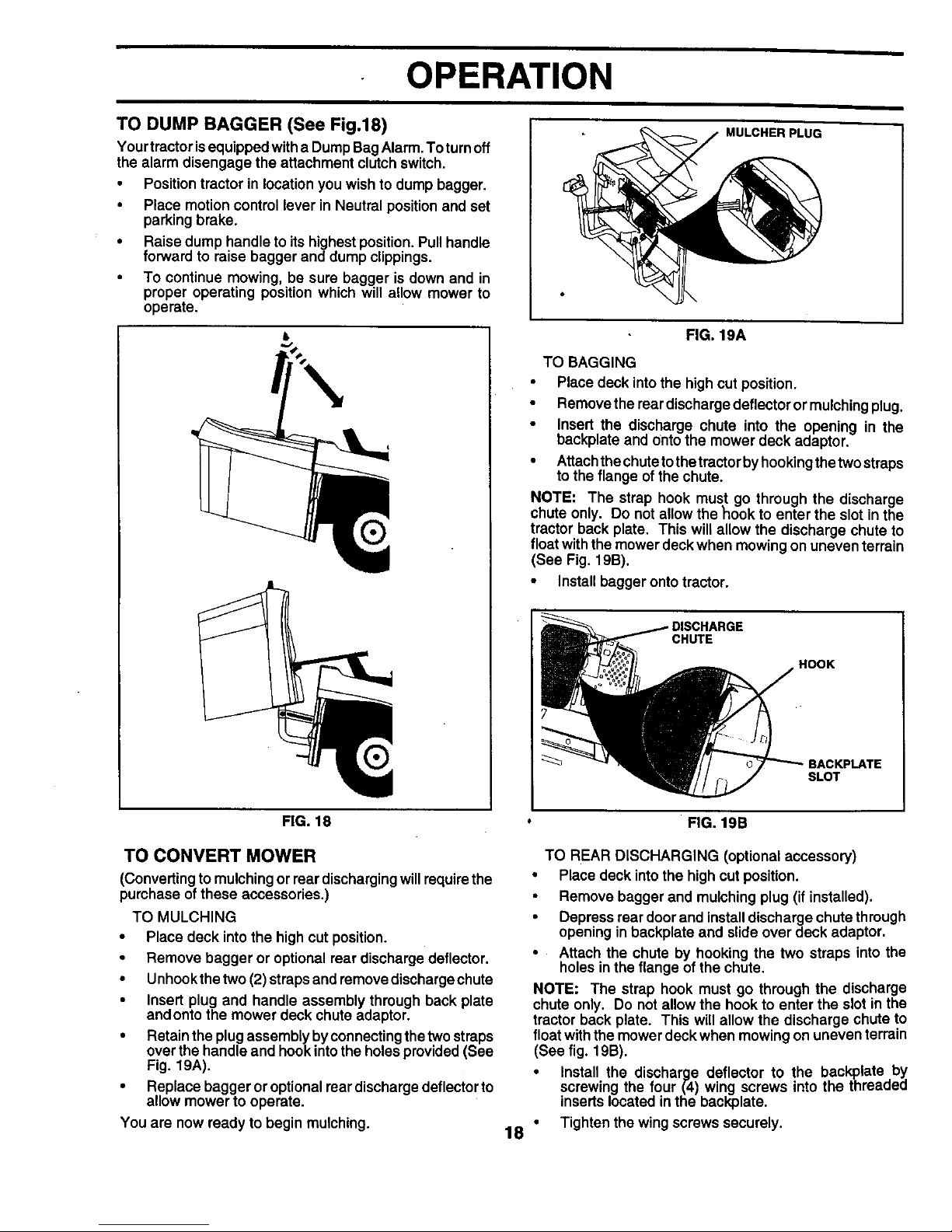
TO DUMP BAGGER (See Fig.18)
Yourtractor is equipped witha Dump Bag Alarm, To turnoff
the alarm disengage the attachment clutch switch.
• Positiontractor in location you wish to dump bagger.
• Place motion control lever in Neutral position and set
parking brake.
• Raise dump handle to its highest position. Pull handle
forward to raise bagger and dump clippings.
• To continue mowing, be sure bagger is down and in
proper operating position which will allow mower to
operate.
FIG. 19A
TO BAGGING
• Place deck intothe high cut position.
• Remove the rear discharge deflector or mulching plug.
• Insert the discharge chute into the opening in the
backplate and ontothe mower deck adaptor.
• Attachthe chuteto thetractor by hooking the twostraps
to the flange of the chute.
NOTE: The strap hook must go through the discharge
chute only. Do not allow the hook to enter the slot in the
tractor back plate. This will allow the discharge chute to
float with the mower deck when mowing on uneven terrain
(See Fig. 19B).
• Install bagger onto tractor.
CHUTE
HOOK
SLOT
FIG. 18
TO CONVERT MOWER
(Converting to mulching or rear discharging will require the
purchase of these accessories.)
TO MULCHING
• Place deck into the high cut position.
• Remove bagger or optional rear discharge deflector.
• Unhook the two (2) straps and remove discharge chute
• Insert plug and handle assembly through back plate
and onto the mower deck chute adaptor.
• Retain the plug assembly byconnecting the two straps
over the handle and hook into the holes provided (See
Fig. 19A).
• Replace bagger or optional rear discharge deflector to
allow mower to operate.
You are now ready to begin mulching.
FIG. 19B
TO REAR DISCHARGING (optional accessory)
• Place deck intothe high cut position.
• Remove bagger and mulching plug (if installed).
• Depress rear door and install discharge chute through
opening in backplate and slide over deck adaptor.
• Attach the chute by hooking the two straps into the
holes in the flange of the chute.
NOTE: The strap hook must go through the discharge
chute only. Do not allow the hook to enter the slot inthe
tractor back plate. This will allow the discharge chute to
float with the mower deck when mowing on uneven terrain
(See fig. 19B).
• Install the discharge deflector to the backplate by
screwing the four (4) wing screws into the threaded
inserts located in the back,plate.
18 " Tighten the wing screws securely.
 Loading...