

Craftsman 944.609050 Owner's Manual

OWNER'S
MANUAL
MODEL NO.
944.609050
Caution:
Read and follow
all Safety Rules
and Instructions
Before Operating
This Equipment
£RAFTXMAN
15.5 HP
ELECTRIC START
42" MOWER
6 SPEED TRANSAXLE
LAWN TRACTOR
• Assembly
• Operation
• Customer Responsibilities
• Service and Adjustments
• Repair Parts
Sears Canada, Inc., Toronto, Ontario M5B 2B8
SAFETY RULES &
Safe Operation Practices for Ride-On Mowers
IMPORTANT: THIS CUTTING MACHINE IS CAPABLE OF AMPUTATING HANDS AND FEET AND THROWING
OBJECTS. FAILURE TO OBSERVE THE FOLLOWING SAFETY INSTRUCTIONS COULD RESULT IN SERIOUS
INJURY OR DEATH.
I. GENERALOPERATION
• Read, understand, and follow all instructions in the manual
and on the machine before starting.
• Only allow responsible adults, who are familiar with the
instructions, to operate the machine.
Clear the area of objects such as rocks, toys, wire, etc.,
which could be picked up and thrown by the blade.
• Be sure thearea isclear of other people before mowing. Stop
machine if anyone enters the area.
• Never carry passengers.
• Do not mow in reverse unless absolutely necessary. Always
look down and behind before and while backing.
Be aware of the mower discharge direction and do not point
it at anyone. Do not operate the mower without either the
entire grass catcher or the guard in place.
• Slow down before turning.
• Never leave a running machine unattended. Always turn off
blades, set parking brake, stop engine, and remove keys
before dismounting.
• Tum off blades when not mowing,
• Stop engine before removing grass catcher or unclogging
chute.
• Mow only in daylight or good artificial light.
• Do not operate the machine while under the influence of
alcohol or drugs.
Watch for traffic when operating near or crossing roadways.
• Use extra care when loading or unloading the machine into
a trailer or truck.
II. SLOPE OPERATION
Slopesare a ma or factorrelatedto loss-of-controland tipover
accidents,whichcan resultin severeinjuryordeath. Allslopes
requireextrecaution. Ifyoucannotbackuptheslopeorifyoufeel
uneasyonit,do not mow it.
DO:
• Mowup and downslopes,notacross.
• Removeobstaclessuchas rocks,tree limbs,etc.
• Watch for holes, ruts, or bumps. Uneven terrain could
overtumthemachine, Tallgrasscanhideobstacles.
• Useslowspeed. Choosea lowgearsothatyouwUlnothave
tostopor shiftwhile on the slope.
• Follow the manufacturer's recommendationsfor wheel
weightsorcounterweightsto improvestability.
• Use extra care with grass catchersor otherattachments.
These can changethestabilityofthemachine.
• Keepallmovementonthe slopesslowand gradual. Do not
makesuddenchanges inspeedordirection.
• Avoidstaring or stoppingon a slope, If tireslose traction
disengagethebladesandproceedslowlystraightdownthe
slope.
DO NOT:
• Do not turnon slopes unless necessary, and then, rum slowly
and gradually downhill, if possible.
• Do not mow near drop-offs, ditches, or embankments, The
mower could suddenly turn over if a wheel is over the edge
of a cliff or ditch,_or if an edge caves in.
• Do not mow on wet grass. Reduced traction could cause
sliding.
• Do not try to stabilize the machine by putting your footonthe
ground.
• Do not use grass catcher on steep slopes.
IlL CHILDREN
Tragic accidentscan occurif the operator is not alert to the
presenceofchildren.Childrenareoftenattractedtothemachine
and the mowingactivity.Neverassumethatch drenwillremain
whereyoulastsawthem.
• Keepchildrenoutofthemowingareaandunderthewatchful
care ofanotherresponsibleadult.
• Be alertandtum machineoffifchildrenenterthearea.
• Beforeand whenbacking,look behindand downfor small
chUdren.
• Never carry children. They may fall off and be seriously
injuredor interferewithsafemachineoperation.
Neverallowcl_ildrentooperatethe machine.
• Use extra care when approachingblind corners, shrubs,
trees, orotherobjectsthat may obscurevision,
IV. SERVICE
Useextracareinhandlinggasctineandotherfuels.Theyare
flammable andvaporsare explosive.
Useonlyan approvedcontainer.
Never remove gas cap or add fuel with the engine
running,Allowengineto coolbeforerefueling. Do not
smoke.
Neverrefuelthemachinerndoors.
Neverstorethe machineor fuelcontainerinsidewhere
there isan openflame, suchas a water heater.
• Neverruna machineinsidea closedarea.
• Keepnutsandbolts,especiallybladeattachmentbois,tght
and keep equipmentingoodcondition,
• Never tamper with safety devices. Check their proper
operationregularly.
• Keepmachinefreeofgrass leaves orotherdebdsbu d-up
C ean o or fue spillage. Allowmachineto cool before
storing.
• Stop and inspect the equipment if you strike an object.
Repair,ifnecessary,beforerestarting.
• Nevermakeadjustmentsor repairswiththeenginerunning.
• Grasscatchercomponentsaresubjecttoweardamage and
detedoretion,which could expose movingparts or allow
objectsto be thrown. Frequentlycheckcomponentsand
replacewithmanufacturer'srecommendedparts,whennec-
essary.
• Mowerbladesare sharpandcan cut. Wrap the blade(s)or
weargloves,anduseextracautionwhenservicingthem.
• Check brake operationfrequently. Adjustand serviceas
required.
I & Lookforthissymboltopointoutimpor-
tant safety precautions. It means
CAUTIONI!! BECOME ALERTlll YOUR
SAFETY IS INVOLVED.
CAUTION: Always disconnect spark
plug wire and place wire where Itcannot
contact spark plug In order to prevent
accidental starting when setting up,
transporting, adlustlng or making
repairs.
2

CONGRATULATIONS on your purchase of a Sears
Tractor. It has been designed, engineered and manufac-
tured to give you the best possible dependability and
performance.
Should you experience any problem you cannot easily
remedy, please contact your nearest Sears Authorized
Service Centre/Department. We have competent, well-
trained technicians and the proper tools toservice or repair
this unit.
Please read and retain this manual. The instructionswill
enable you to assemble and maintain your unit properly.
Always observe the "SAFETY RULES".
MODEL
NUMBER 944.609050
SERIAL
NUMBER
DATEOFPURCHASE
THEMODELANDSERIALNUMBERSWlLLBEFOUND
ON A PLATE UNDER THE SEAT.
YOUSHOULDRECORDBOTHSERIALNUMBERAND
DATE OF PURCHASE AND KEEP IN A SAFE PLACE
FOR FUTURE REFERENCE.
MAINTENANCE AGREEMENT
A Sears Maintenance Agreement isavailable on this prod-
uct. Contact your nearest Sears store for details.
CUSTOMER RESPONSIBILITIES
• Read and observe the safety rules.
• Follow a regular schedule in maintaining, cadng for and
using your unit.
• Follow the instructions under"Customer Responsibili-
ties" and "Storage" sections of this owner's manual.
PRODUCT SPECIFICATIONS
HORSEPOWER: 15.5
GASOLINE CAPACITY 1.25 GALLONS
ANDTYPE: UNLEADED REGULAR
OIL TYPE (API-SF/SG/SH): SAE 30 (above32°F)
SAE 5W-30 (below 32°F)
OIL CAPACITY: 3.0 PINTS
SPARK PLUG: CHAMPION RJ19LM
3AP: .030")
VALVE CLEARANCE: INTAKE: .005" - .007'
EXHAUST: .009"- .011"
GROUND SPEED (MPH):
FORWARD:
I st 1.0
2nd 1.3
3rd 2.1
4th 3.1
5th 4.0
6th 5.1
REVERSE: 1.6
TIRE PRESSURE: FRONT: 14PSI
REAR: 12 PSI
CHARGING SYSTEM: 3AMPS BA'I-rERY
5 AMPS HEADLIGHTS
BATTERY: AMP/HR: 25
MIN. CCA: 190
CASE SIZE: U1R
BLADE BOLTTORQUE: 27-35 FT. LBS.
WARNING: This unit is equipped with an internal combus-
tion engine and should not be used on or near any unim-
proved forest-covered, brush-covered or grass-covered
land unless the engine's exhaust system is equipped with
a spark arrester meeting applicable local or state laws (if
any). If a spark arrester is used, it should be maintained in
effective working order by the operator.
A spark arrester for the muffler is available through your
nearest Sears Authorized Service Centre/Department (See
REPAIR PARTS section of this manual).
3
TABLE OF CONTENTS
SAFETY RULES ............................................................ 2
PRODUCT SPECIFICATIONS ...................................... 3
CUSTOMER RESPONSIBILITIES ..................... 3, 15-18
WARRANTY ..................... ............................................ 4
ASSEMBLY ................................................................ 6-8
OPERATION ............................................................. 9-14
MAINTENANCE SCHEDULE ...................................... 15
SERVICE AND ADJUSTMENTS ............................ 19-24
STORAGE .................................. ................................. 25
TROUBLESHOOTING ............................................ 26-27
REPAIR PARTS - TRACTOR ................................. 30-47
REPAIR PARTS - ENGINE .................................... 48-53
PARTS ORDERING/SERVICE ................ BACK COVER
LIMITED TWO (2) YEAR WARRANTY ON CRAFTSMAN TRACTOR (RIDING EQUIPMENT)
Fortwo(2) yearsfromdate ofpurchaseSears Canada, Inc.willrepairorreplace at Searsoptionfree ofcha_e partswhichare
defectiveas a resultof material orworkmanship.
FULL ONE (1) YEAR WARRANTY ON BATI'ERY
For one (1) year from date of purchase, if any battery includedwith this ridingequipmentprovesdefectivein material or
workmanshipandourtestingdeterminesthebatterywillnotholda charge,Searswillreplacethebatteryat nocharge.
COMMERCIAL OR RENTAL USE
Warrantyon RidingEquipmentusedforcommercialor rentalpurposesislimiteclto ninety(90) days.
This Warranty does NOT cover:
1. Pre-deUveryset-up.
2. Tire replacement or repair caused by puncturesfrom outside objects (such as nails, thorns, stumps, or glass).
3. Expendable itemswhich become worn during normal use, such as blades, spark plug, air cleanersend belts.
4. Repairs necessary because of operator abuse or negligence, including damaged jackshaft or mandrel end the
failure to operate and maintain the equipmentaccording to the instructionscontained In the Owner's Manual.
5. In Home service.
Warrantyserviceisavailable by returningtheCraftsmanRidingEquipmentto the nearestSears ServiceCentre/Departmentin
Canada. This warrantyappliesonlywhilethisproductis inuseinCanada.
This warrantyis in additionto any statutorywarrantyand does not excludeor limitlegal rightsyou may have but shall run
concurrentlywithapplicableprovinciallegislation.Furthermore,someprovincesdo NOT allowlimitationon howlongan implied
warrantywilllastso the abovelimitationsmaynotapplytoyou,
SEARS CANADA, INC., TORONTO, ONTARIO MSB 2B8
4
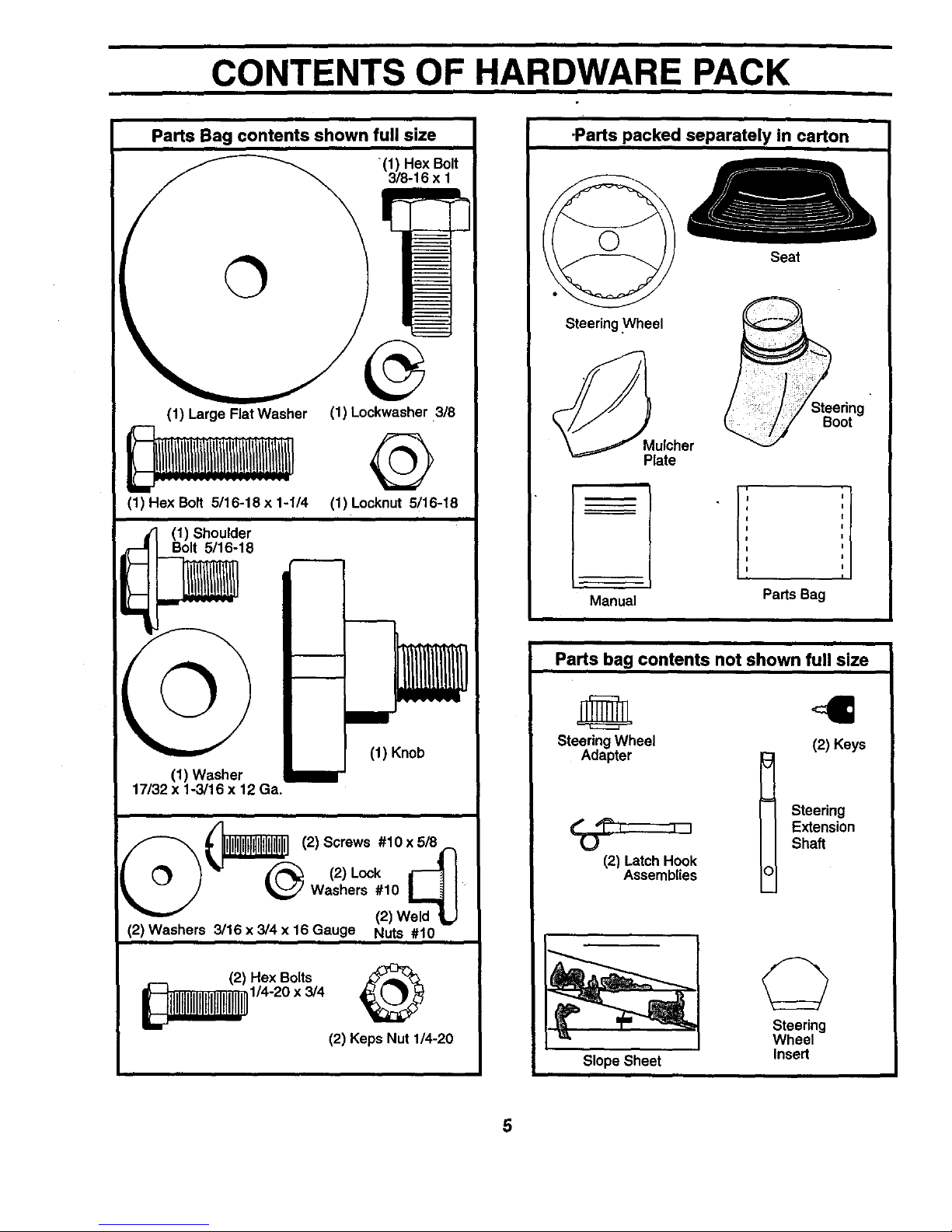
CONTENTS OF HARDWARE PACK
Parts Bag contents shown full size
(1) Hex Bolt
3/8-16 x 1
(1) Large Flat Washer
(1) Hex Bolt 5/16-18 x 1-1/4
(1) Lockwasher 3/8
@
(1) Locknut 5/16-18
(1) Shoulder
Bolt 5/16-18
©
(1) Washer
17/32 x 1-3/16 x 12 Ga.
I
(1) Knob
(2) Screws #10 x 5/8
(2)Lock M1
(_ _ Washers #10 L,_ I
(2) Weld
(2) Washers 3/16 x 3/4 x 16 Gauge Nuts #10
-Parts packed separately in carton
Steering Wheel
Seat
Boo
Plate
I' ;I
Manual Parts Bag
Parts bag contents not shown full size
Steering Wheel (2) Keys
Adapter t Steering
Extension
Shaft
(2) Latch Hook
Assemblies
Slope Sheet
Steering
Wheel
Insert
5
i
ASSEMBLY
Your new tractor has been assembled atthe factory with exception of those parts leftunassembled for shipping purposes.
To ensure safe and proper operation ofyour tractor all parts and hardware you assemble must be tightened securely. Use
the correct tools as necessary to insure proper tightness.
TOOLS REQUIRED FOR ASSEMBLY
A socket wrench set willmake assembly easier. Standard
wrench sizes are listed.
(2) 7/16' wrenches Utility knife
(1) 9/16" wrench Tire pressure gauge
(2) 1/2" wrenches Phillips screwdriver
When right or left hand is mentioned in this manual, it
means when you are in the operating position (seated
behind the steering wheel).
TO REMOVE TRACTOR FROM CARTON
UNPACK CARTON
• Remove all accessible loose parts and parts cartons
from carton (See page 5).
• Cut, from top to bottom, along lines on all four corners
of carton, and lay panels flat.
• Check for any additional loose parts or cartons and
remove.
BEFORE ROLLING TRACTOR OFF SKID
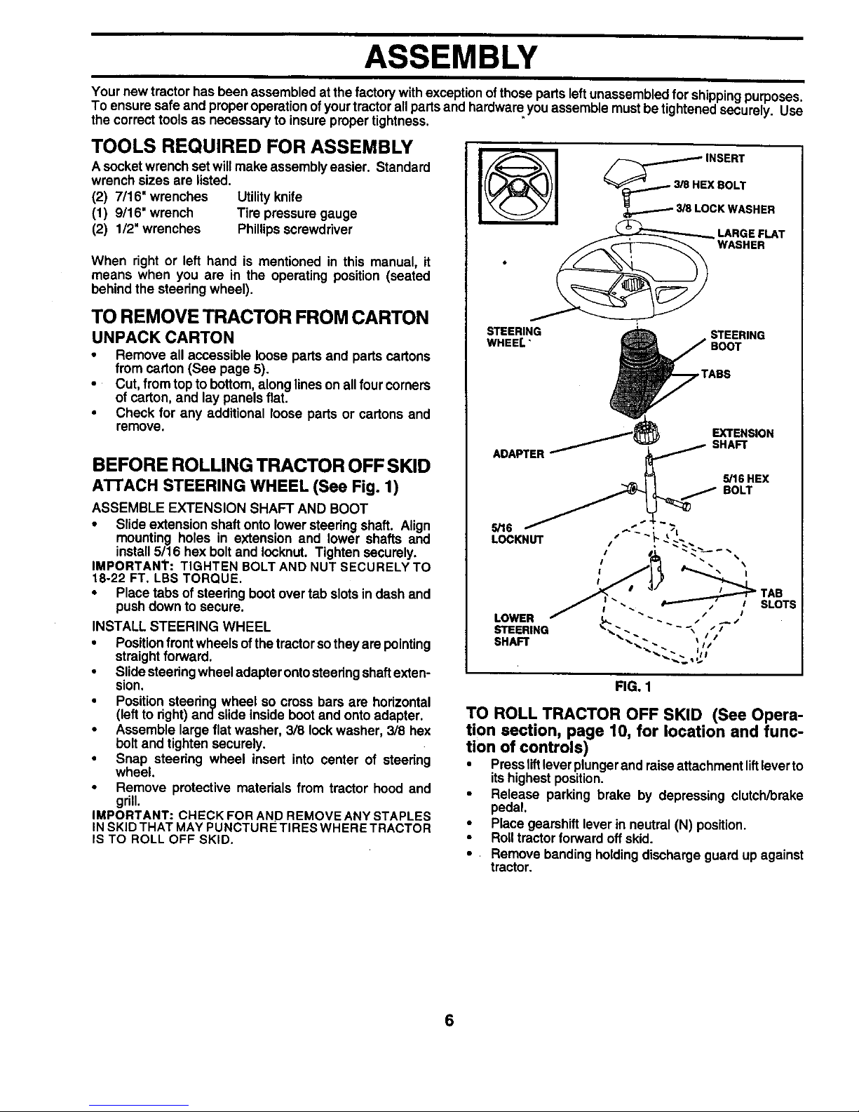
ATTACH STEERING WHEEL (See Fig. 1)
ASSEMBLE EXTENSION SHAFT AND BOOT
• Slide extension shaft onto lower steering shaft. Align
mounting holes in extension and lower shafts and
install 5/16 hex bolt and Iocknut. Tighten securely.
IMPORTANT: TIGHTEN BOLT AND NUT SECURELY TO
18-22 FT. LBS TORQUE.
• Place tabs of steering boot over tab slots in dash and
push down to secure.
INSTALL STEERING WHEEL
• Position frontwheels of the tractor so they are pointing
straight forward.
• Slide steedng wheel adapter ontosteering shaft exten-
sion,
• Position steedng wheel so cross bars are horizontal
(left to right) ands,de inside boot and onto adapter.
• Assemble large flat washer, 3/8 lock washer, 3/8 hex
bolt and tighten securely.
• Snap steering wheel insert into center of steedng
wheel.
• Remove protective materials from tractor hood and
grill.
IMPORTANT: CHECK FOR AND REMOVE ANY STAPLES
IN SKID THAT MAY PUNCTURE TIRES WHERE TRACTOR
IS TO ROLL OFF SKID.
I@1
___BHE INSERT
X BOLT
LOCK WASHER
LARGE FLAT
WASHER
STEERING STEERING
WHEEL"
FIG. 1
TO ROLL TRACTOR OFF SKID (See Opera-
tion section, page 10, for location and func-
tion of controls)
• Press liftleverplunger and raise attachment liftlever to
its highest position.
• Release parking brake by depressing clutch/brake
pedal.
• Place gearshift lever in neutral (N) position.
• Roll tractor forward off skid.
• Remove banding holding discharge guard up against
tractor.
6
ASSEMBLY
HOW TO SET UP YOUR TRACTOR
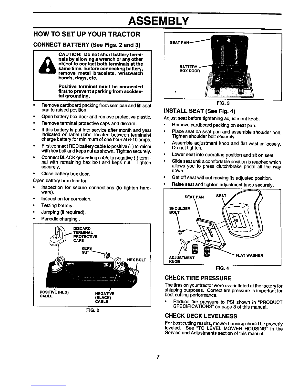
CONNECT BA'I-rERY (See Figs. 2 and 3)
&
CAUTION: Do not short battery termi-
nals by allowing a wrench or any other
object to contact both terminals at the
sametime. Beforeconnecting battery,
remove metal bracelets, wristwatch
bands, rings, etc.
Positive terminal must be connected
first to prevent sparking from acclden-
tat grounding.
Remove cardboard packing from seat pan and lift seat
pan to raised position.
• Open battery box door and remove protective plastic.
• Remove terminal protective caps and discard.
• If this battery is put into service after month and year
indicated on label (label located between terminals)
charge battery for minimum of one hour at 6-10 amps.
• Firstconnect RED battery cable to positive (+) terminal
with hex boltand keps nutas shown. Tighten securely.
• Connect BLACK grounding cableto negative (-) termi-
nal with remaining hex bolt and keps nuL Tighten
securely.
• Close battery box door.
Open battery box door for:
• Inspection for secure connections (to tighten hard-
ware).
• Inspection for corrosion.
• Testing battery.
• Jumping (if required).
• Periodic charging.
DISCARD
TERMINAL
PROTECTIVE
CAPS
KEPS
i! NUT"_.
HEXBOLT
POSITIVE (RED) NEGATIVE
CABLE (BLACK i
CABLE
FIG. 2
SEATPAN/
BOX DOOR
FIG. 3
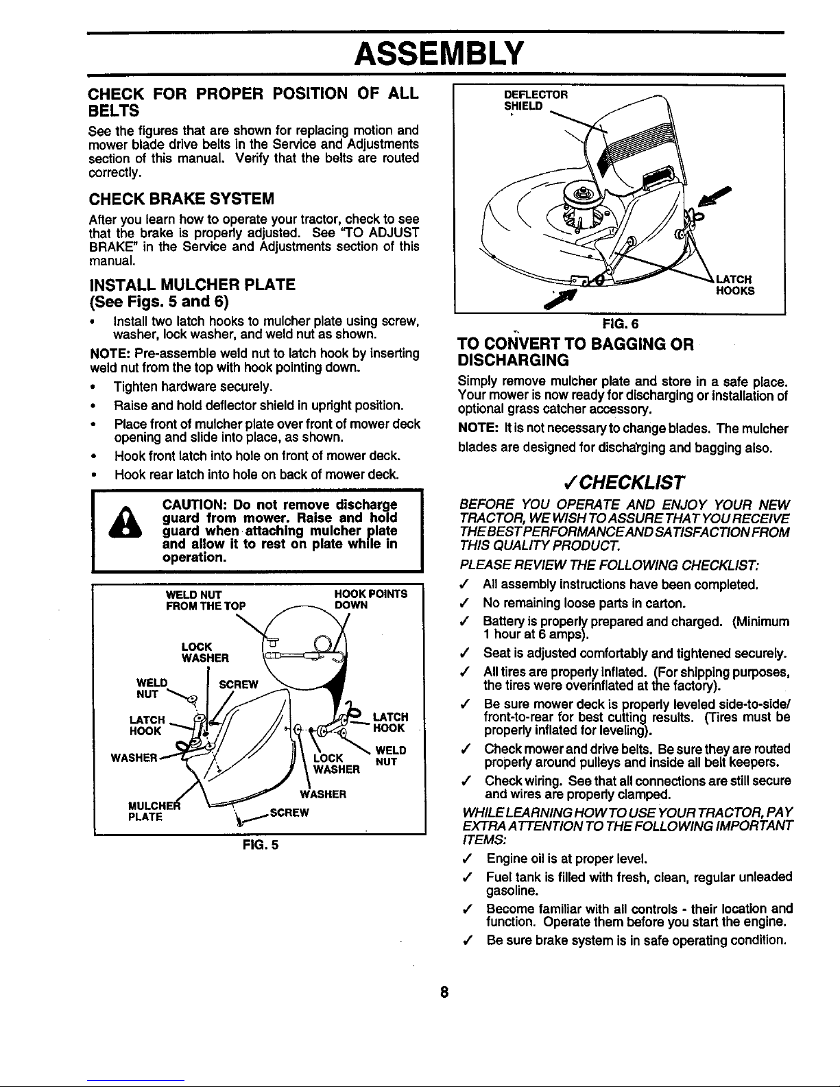
INSTALL SEAT (See Fig. 4)
Adjust seat before tightening adjustment knob.
• Remove cardboard packing on seat pan,
• Place seat on seat pan and assemble shoulder bolt.
Tighten shoulder bolt securely.
• Assemble adjustment knob and flat washer loosely,
Do not tighten.
• Lower seat into operating position and siton seat.
• Slide seat untila comfortable position isreached which
allows you to press clutch/brake pedal all the way
down.
• Get off seat without moving its adjusted position.
• Raise seat and tighten adjustment knob securely.
SEAT PAN SEAT
SHOULDER
BOLT
ADJUSTMENT
KNOB
FIG. 4
CHECK TIRE PRESSURE
The tires on yourtractor were overinflated at the factory for
shipping purposes. Correct tire pressure is important for
best cutting performance.
• Reduce tire pressure to PSI shown in =PRODUCT
SPECIFICATIONS on page 3 of this manual
CHECK DECK LEVELNESS
For bestcutting results, mower housing should be properly
leveled. See "TO LEVEL MOWER HOUSING" in the
Service and Adjustments section of this manual.
7
ASSEMBLY
CHECK FOR PROPER POSITION OF ALL
BELTS
See the figures that are shown for replacing motion and
mower blade drive belts in the Service and Adjustments
section of this manual. Verify that the belts are muted
correctly.
CHECK BRAKESYSTEM
After you learn how to operate your tractor, check to see
that the brake is pmpedy adjusted. See "TO ADJUST
BRAKE" in the Service and Adjustments section of this
manual.
INSTALL MULCHER PLATE
(See Figs. 5 and 6)
• install two latch hooks to mulcher plate using screw,
washer, lock washer, and weld nut as shown.
NOTE: Pra-assemble weld nut to latch hook by inserting
weld nut from the top with hook pointing down.
• Tighten hardware securely.
• Raise and hold deflector shield in upright position.
• Place front of muicher plate over front of mower deck
opening and slide into place, as shown.
• Hook front latch into hole on front of mower deck.
• Hook rear latch into hole on back of mower deck.
&
CAUTION: Do not remove discharge
guard from mower. Raise and hold
guard when attaching mulcher plate
and allow it to rest on plate while in
operation.
WELD NUT HOOK POINTS
FROMTHE TOP DOWN
LOCK
WASHER
WELD
NUT '_,
LATCH
HOOK
LOCK
WASHER
PLATE
WASHER
'¥...,_._SCREW
FIG. 5
LATCH
WELD
NUT
DEFLECTOR
SHIELD
h,LATCH
HOOKS
FIG. 6
TO CoI_VERT TO BAGGING OR
DISCHARGING
Simply remove mulcher plate and store in a safe place.
Your mower is now ready for discharging or installation of
optional grass catcher accessory.
NOTE: It is not necessaryto change blades. The mulcher
blades are designed for discharging and bagging also.
/ CHECKLIST
BEFORE YOU OPERATE AND ENJOY YOUR NEW
TRACTOR, WE WISH TOASSURE THAT YOU RECEIVE
THE BEST PERFORMANCE AND SATISFACTION FROM
THIS QUALITY PRODUCT.
PLEASE REVIEW THE FOLLOWING CHECKLIST:
•/ All assembly instructions have been completed.
/ No remaining loose parts in carton.
,/ Battery is propedy prepared and charged. (Minimum
1 hour at 6 amps).
/ Seat is adjusted comfortably and tightened securely.
,/ Alltires are propedy inflated. (For shippingpurposes,
the tires were overinflated at the factory).
/ Be sure mower deck is properly leveled side-to-side/
front-to-rear for best cutting results. (Tires must be
propedy inflated for leveling).
,/ Check mower and drive belts. Be sure they are routed
propedy around pulleys and inside all belt keepers.
/ Check wiring. See that all connections are still secure
and wires are propedy clamped.
WHILE LEARNING HOW TO USE YOUR TRACTOR, PAY
EXTRA ATTENTION TO THE FOLLOWING IMPORTANT
ITEMS:
/ Engine oil is at proper level.
,/ Fuel tank is filled with fresh, clean, regular unleaded
gasoline.
,/ Become familiar with all controls - their location and
function. Operate them before you start the engine.
/ Be sure brake system is in safe operating condition.
8
OPERATION
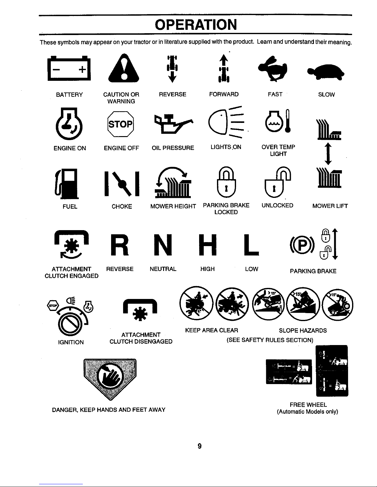
These symbols may appear on your tractor or in literature supplied with the product. Learn and understand their meaning.
BAI-IE RY CAUTION OR REVERSE FORWARD FAST SLOW
WARNING
ENG,NEONENG,NEOFFO,LPRESSUREL,GHTSONO%_MP ]_
FUEL CHOKE MOWER HEIGHT PARKING BRAKE UNLOCKED MOWER LIFT
LOCKED
R N H L
A'i-rACHMENT REVERSE NEUTRAL HIGH LOW
CLUTCH ENGAGED
IGNITION
A'I-rACHMENT
CLUTCH DISENGAGED
PARKING BRAKE
KEEP AREA CLEAR SLOPE HAZARDS
(SEE SAFETY RULES SECTION)
DANGER, KEEP HANDS AND FEET AWAY
FREE WHEEL
(Automatic Models only)
9
OPERATION
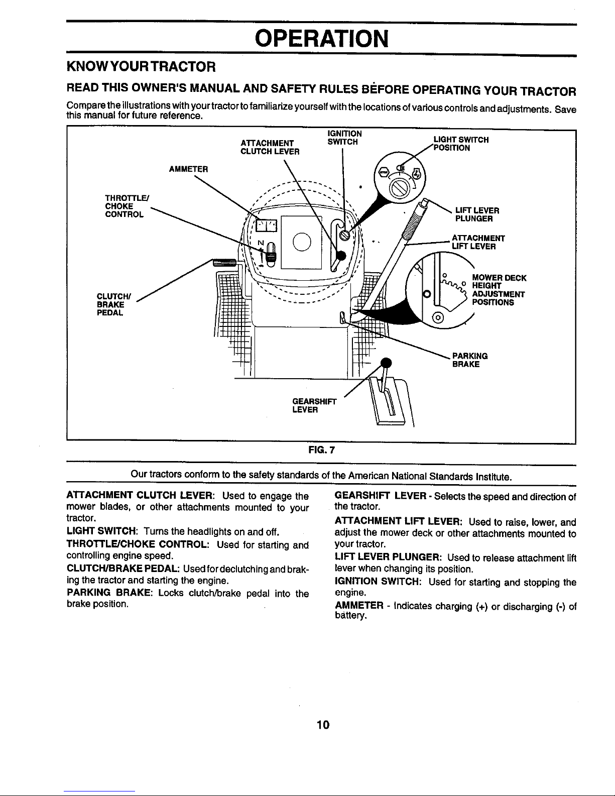
KNOW YOUR TRACTOR
READ THIS OWNER'S MANUAL AND SAFETY RULES B_:FORE OPERATING YOUR TRACTOR
Compare the illustrations with your tractor to familiarize yourself withthe locations ofvarious controls andadjustments. Save
this manual for future reference.
ATTACHMENT
CLUTCH LEVER
IGNITION
SWITCH LIGHT SWITCH
AMMETER
THROTTLE/
CHOKE LIFT LEVER
CONTROL PLUNGER
ATTACHMENT
LIFT LEVER
MOWER DECK
HEIGHT
ADJUSTMENT
POSITIONS
_.PARKING
BRAKE
GEARSHIFT
LEVER
FIG. 7
Our tractors conform to the safety standards of the American National Standards Institute.
ATTACHMENT CLUTCH LEVER: Used to engage the
mower blades, or other attachments mounted to your
tractor.
LIGHT SWITCH: Turns the headlights on and off.
THROTTLE/CHOKE CONTROL: Used for starting and
controllingengine speed,
CLUTCH/BRAKE PEDAL: Used fordeclutching and brak-
ingthe tractor and starting the engine.
PARKING BRAKE: Locks clutch/brake pedal into the
brake position,
GEARSHIFT LEVER - Selects the speed and direction of
the tractor.
ATTACHMENT LIFT LEVER: Used to raise, lower, and
adjust the mower deck or other attachments mounted to
your tractor.
LIFT LEVER PLUNGER: Used to release attachment lift
lever when changing its position.
IGNITION SWITCH: Used for starting and stopping the
engine.
AMMETER - Indicates charging (+) or discharging (-) of
battery.
10
OPERATION
The operation of any tractor can result in foreign objects thrown into the eyes, which
can result in severe eye damage. Always wear safety glasses or eye shields while
opereting your tractor or performing any adju stmente or repairs. We recom mend a wide
vision safety mask over spectacles or standard safety glasses.
HOW TO USE YOUR TRACTOR
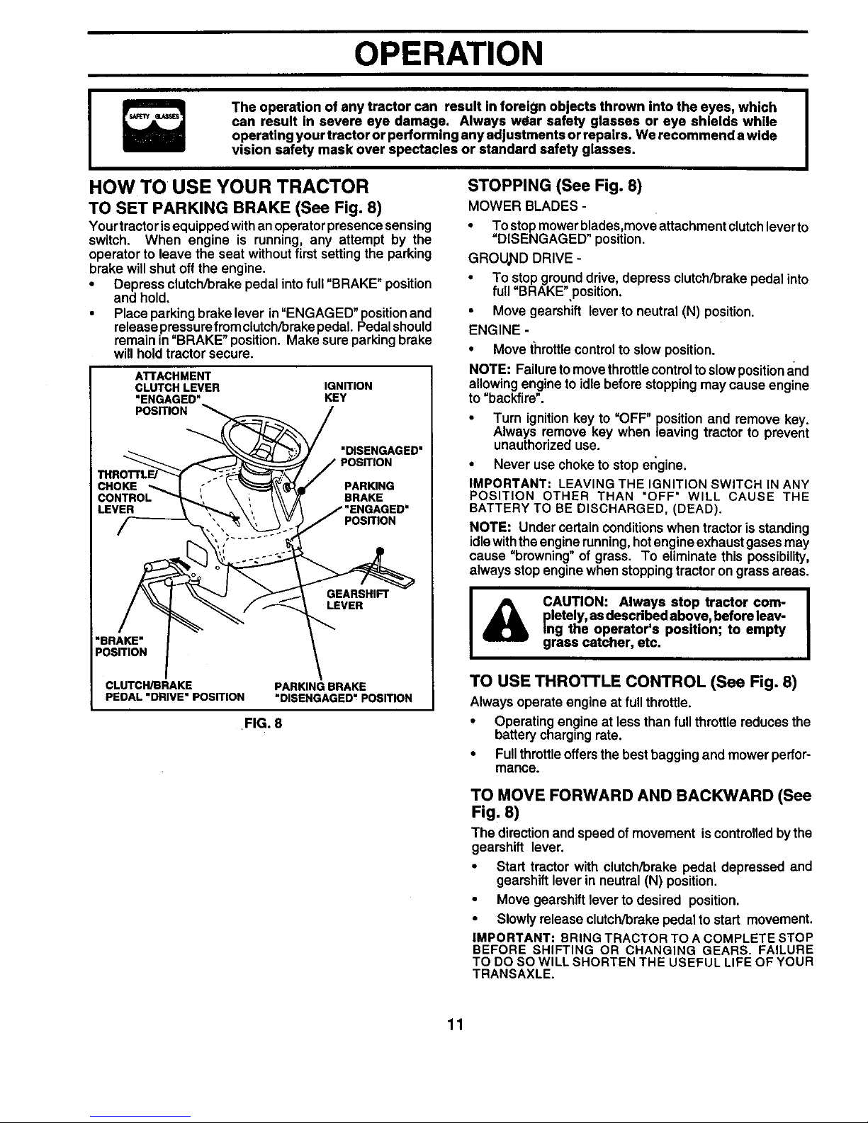
TO SET PARKING BRAKE (See Fig. 8)
Yourtractor isequipped with an operator presence sensing
switch. When engine is running, any attempt by the
operator to leave the seat without first setting the parking
brake will shut off the engine.
• Depress clutch/brake pedal into full "BRAKE" position
and hold,
• Place parking brake lever in"ENGAGED" position and
release pressure fromclutch/brake pedal. Pedal should
remain in =BRAKE"position. Make sure parking brake
will hold tractor secure.
ATTACHMENT
CLUTCH LEVER IGNITION
"ENGAGED" KEY
POSITION
CHOKE
LEVER
"DISENGAGED"
POSITION
PARKING
BRAKE
POSITION
GEARSHIFT
LEVER
"BRAKE"
POSITION
CLUTCH/BRAKE
PEDAL"DRIVE" POSITION
PARKING BRAKE
"DISENGAGED"POSmON
FIG. 8
STOPPING (See Fig. 8)
MOWER BLADES -
• To stop mower blades,move attachment dutch leverto
=DISENGAGED" position.
GROUND DRIVE -
• To stop ground drive, depress clutch/brake pedal into
full=BRAKE",position.
• Move gearshift lever to neutral (N) position.
ENGINE -
• Move t'hrettlecontrol to slow position.
NOTE: Failure to move throttle control to slowpositionand
allowing engine to idle before stopping may cause engine
to "backfire".
• Turn ignition key to "OFF" position and remove key.
Always remove key when leaving tractor to prevent
unauthorized use.
• Never use choke to stop er;gine.
IMPORTANT: LEAVING THE IGNITION SWITCH IN ANY
POSITION OTHER THAN "OFF" WILL CAUSE THE
BATTERY TO BE DISCHARGED, (DEAD).
NOTE: Under cerfain conditions when tractor is standing
idlewith theengine running, hotengine exhaust gases may
cause "browning"of grass. To eliminate this possibility,
always stop engine when stopping tractor on grass areas.
J& AUTION: Always stop tractor com- J
pletely, as described above, before leav-
Ing the operator's position; to empty
grass catcher, etc.
TO USE THROTTLE CONTROL (See Fig. 8)
Always operate engine at full throttle.
• Operating engine at less than full throttle reduces the
battery charging rate.
• Full throttleoffers the best bagging and mower perfor-
mance.
TO MOVE FORWARD AND BACKWARD (See
Fig. 8)
The direction and speed of movement is controlled by the
gearshift lever.
• Start tractor with clutch/brake pedal depressed and
gearshift lever in neutral (N) position.
• Move gearshift lever to desired position.
• Slowly release clutch/brake pedal to start movement.
IMPORTANT: BRING TRACTOR TO A COMPLETE STOP
BEFORE SHIFTING OR CHANGING GEARS. FAILURE
TO DO SO WILL SHORTEN THE USEFUL LIFE OF YOUR
TRANSAXLE.
11
OPERATION
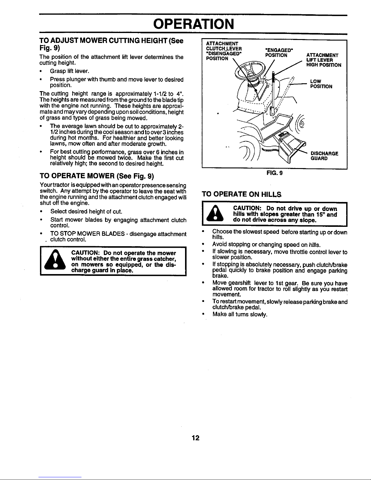
TO ADJUST MOWER cu'n'ING HEIGHT (See
Fig. 9)
The position of the attachment lift lever determines the
cutting height.
• Grasp lift lever.
• Press plunger with thumb and move lever to desired
position.
The cutting height range is approximately 1-1/2 to 4".
The heights are measured from the ground tothe blade tip
with the engine not running. These heights are approxi-
mate and may vary depending uponsoilconditions, height
of grass and types of grass being mowed.
• The average lawn should be cut to approximately 2-
1/2 inchesduring the coolseason and to over 3 inches
during hot months. For healthier and better looking
lawns, mow often and after moderate growth.
• For best cuttingperformance, grass over 6 inches in
height should be mowed twice. Make the first cut
relatively high; the second to desired height.
TO OPERATE MOWER (See Fig. 9)
Your trector isequipped withan operator presence sensing
switch. Any attempt by the operator to leave the seat with
the engine running and the attachment clutchengaged will
shut off the engine.
• Select desired height of cut.
• Start mower blades by engaging attachment clutch
control.
• TO STOP MOWER BLADES - disengage attachment
• clutch control.
CAUTION: Do not operate the mower I
without either the entire grass catcher,
I
on mowers so equipped, or the dis-
charge guard in place.
ATTACHMENT
CLUTCH.LEVER
"DISENGAGED"
POSITION
"ENGAGED"
POSITION ATTACHMENT
LIFT LEVER
HIGH POSITION
DISCHARGE
GUARD
FIG. 9
TO OPERATE ON HILLS
CAUTION: Do not drive up or down I
hills with slopes greater than 15° and
I
do not drive across any slope.
• Choose the slowest speed before starting up or down
hills.
• Avoid stopping or changing speed on hills.
• If slowing is necessary, move throttle control lever to
slower position.
• If stopping is absolutely necessary, push clutch/brake
pedal quickly to brake position and engage parking
brake.
• Move gearshift lever to 1st gear. Be sure you have
allowed room for tractor to roll slightly as you restart
movement.
• To restart movement, slowly release parkingbrake and
clutch/brake pedal.
• Make all turns slowly.
12
OPERATION
TO TRANSPORT
• Raise attachment lift to highest position with attach-
ment lift control.
• When pushing or towing your tractor, be sure gearshift
lever is in neutral (N) position.
• Do not push or tow tractor at more than five (5) MPH.
NOTE: To protect hood from damage when transporting
your tractor ona truck or a trailer, be sure hood is closed and
secured to tractor. Use an appropriate means of tying hood
to tractor (rope, cord, etc.).
BEFORE STARTING THE ENGINE
CHECK ENGINE OIL LEVEL (See Fig. 15)
• Theengineinyourtractor has been shipped, fromthe
factory, already filled with summer weight oil.
• Check engine oil with tractor on level ground.
• Remove oil fill cap/dipstick and wipe clean, reinsert the
dipstick and screw cap tight, wait for a few seconds,
remove and read oil level. If necessary, add oil until
"FULL" mark on dipstick is reached. Do not overfill.
• For cold weather operation you should change oil for
easier starting (See "OIL VISCOSITY CHART" in the
Customer Responsibilities section of this manual).
• To change engine oil, see the Customer Responsibili-
ties section in this manual.
ADD GASOLINE
• Fill fuel tank. Use fresh, clean, regular unleaded
gasoline with a minimum of 87 octane. (Use of leaded
gasoline will increase carbon and lead oxide deposits
and reduce valve life). Do not mix oil with gasoline.
Purchase fuel in quantities that can be used within 30
days to assure fuel freshness.
IMPORTANT: WHEN OPERATING IN TEMPERATURES
BELOW 32°F(0°C), USE FRESH, CLEAN WINTER GRADE
GASOLINE TO HELP INSURE GOOD COLD WEATHER
STARTING.
WARNING: Experience indicates that alcohol blended
fuels (called gasohol or using ethanol or methanol) can
attract moisture which leads to separation and formation of
acids during storage. Acidic gas can damage the fuel
system of an engine while in storage. To avoid engine
problems, the fuel system should be emptied before stor-
age of 30 days or longer. Drain the gas tank, start the
engine and let it run until the fuel lines and carburetor are
empty. Use fresh fuel next season. See Storage Instruc-
tions for additional information. Never use engine or
carburetor cleaner products in the fuel tank or permanent
damage may occur.
I_ CAUTION: Fill to bottom of gas tank |
m
filler neck. Do not overfill. Wipe off any
I
spilled oil or fuel. Do not store, spill or
use gasoline near an open flame.
TO START ENGINE (See Fig. 7)
When staging the engine for the first time or if the engine
has run out of fuel, it will take extra cranking time to move
fuel from the tank to the engine.
• Sit on seat in operating position, depress clutch/brake
pedal and set parking brake.
• Place gear shift lever in neutral (N) position.
• Move attachment clutch to"DISENGAGED" position.
• Move throttle control to choke (IXI) position.
NOTE: Before starting, read the warm and cold starting
proced'ures below.
• Insertkey intoignitionandturn keyclockwiseto "START"
position and release keyas soon as engine starts. Do
not run starter continuously for more than fifteen sec-
onds per minute. If the engine does not start after
several attempts, move throttle controltofast position,
wait afew minutes and try again. Ifengine stilldoes not
start, move the throttle control back to the choke (1\1)
position and retry.
WARM WEATHER STARTING (50 ° F and above)
• When engine starts, move thethrottle controlto the fast
position.
• The attachments and grounddrivecan now be used. If
the engine does notaccept the load, restart the engine
and allow it to warm up for one minute usingthe choke
as described above.
COLD WEATHER STARTING ( 50° F and below)
• When engine starts, aUowengine to run withthethrottle
control in the choke (IXI) position until the engine runs
roughly, then move throttle control to fast position. This
may require an engine warm-up period from several
seconds to several minutes, depending on the tem-
perature.
• The attachments can also be used during the engine
warm-up period.
NOTE: If at a high altitude (above 3000 feet) or in cold
temperatures (below 32 F) the carburetor fuel mixture may
need to be adjusted for best engine performance. See "TO
ADJUST CARBURETOR" in the Service and Adjustments
section of this manual.
13
OPERATION
MOWING TIPS MULCHING MOWING TIPS
• Tire chains cannot be used whenthe mower housing is
attached to tractor.
• Mower should be properly leveled for best mowing
performance. See TO LEVEL MOWER HOUSING" in
the Service and Adjustments section of this manual.
• The left hand side of mower should be used for trim-
ming.
• Drive so that clippings are discharged onto the area
that has been cut. Have the cut area to the right of the
machine. This will result in a more even distribution of
clippings and more uniform cutting.
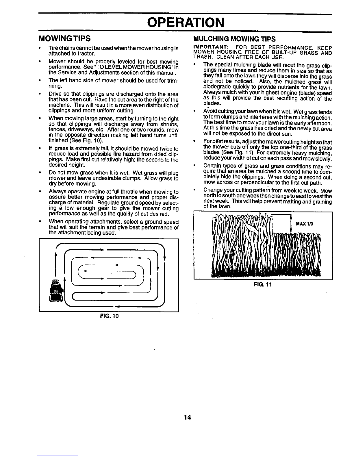
• When mowing large areas, start by turning to the right
so that clippings will discharge away from shrubs,
fences, driveways, etc. After one or two rounds, mow
in the opposite direction making left hand turns until
finished (See Fig. 10).
• If grass is extremely tall, it should be mowed twice to
reduce load and possible fire hazard from dried clip-
pings. Make first cut relatively high; the second tothe
desired height.
• Do not mow grass when it is wet. Wet grass will plug
mower and leave undesirable clumps. Allow grass to
dry before mowing.
• Always operate engine at full throttle when mowing to
assure better mowing performance and proper dis-
charge of matedal. Regulate ground speed by select-
ing a low enough gear to give the mower cutting
performance as well as the quality of cut desired.
• When operating attachments, select a ground speed
that will suit the terrain and give best performance of
the attachment being used.
(
JJ
FIG. 10
IMPORTANT: FOR BEST PERFORMANCE, KEEP
MOWER HOUSING FREE OF BUILT-UP GRASS AND
TRASH. CLEAN AFTER EACH USE.
• The special mulching blade will recut the grass clip-
pings many times and reduce them in size so that as
they fall ontothe lawn they will disperse into the grass
and not be noticed. Also the mulched grass will
b odegrade quickly to provide nutrients for the lawn.
Always mulch with your highest engine (blade) speed
as this will provide the best recutting action of the
blades.
• A_,oidcuttingyour lawn when it iswet. Wet grass tends
toform clumps and interferes withthe mulchingaction.
The besttime to mow your lawn isthe eady afternoon.
Atthis time the grass has dded and the newly cut area
will not be exposed to the direct sun.
• Forb_'stresults, adjustthe mower cuttingheight so that
the mower cuts off only the top one-third of the grass
blades (See Fig. 11). For extremely heavy mulching,
reduce your widthofcut oneach passand mow slowly.
• Certain types of grass and grass conditions may re-
quire that an area be mulched a second time to com-
pletely hide the clippings. When doing a second cut,
mow across or perpendicu!ar to the first cut path.
• Change your cutting pattern from week to week. Mow
northtosouthone week then change to east towest the
nextweek. This willhelp prevent matting and graining
of the lawn.
FIG. 11
MAX 1/3
14
CUSTOMER RESPONSIBILITIES
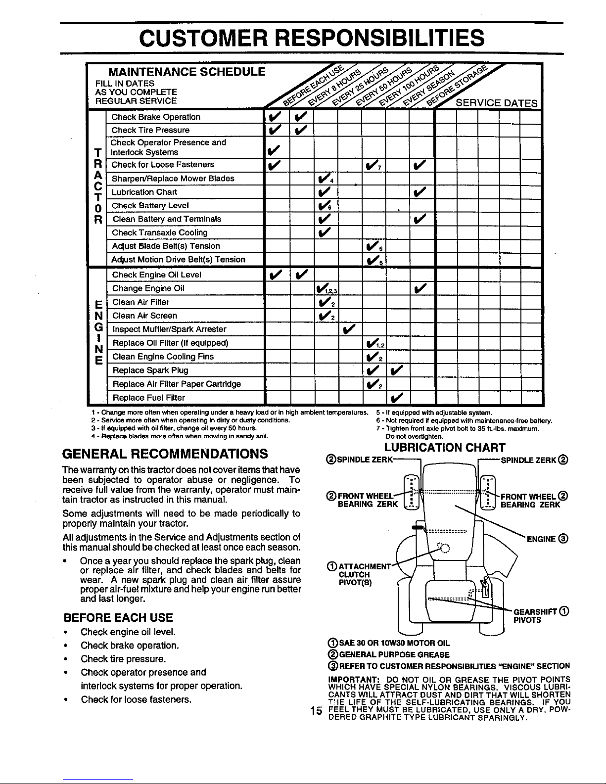
MAINTENANCE SCHEDULE j__,/._o_/_/_j_ ''
F,'L,NOATES
AS YOU COMPLETE
REGULAR SERVICE f__'>__; _SERVICE DATES
Check Operator Presence and
T Interlock Systems V'
Check for Loose Fasteners V _ _7 if
Sharpen/Replace Mower Blades 1_4
T Lubrication Chart K Vw
0 Check Battery Level
R Clean Battery and Terminals I_
Check Transaxle Cooling If
Adjust Blade Belt(s) Tension V_s
Adjust Motion Ddve Belt(s) Tension ills
Check Engine Oil Level _ I_
Change Engine Oil 1_1,2.3 If
E Clean Air Filter
Clean Air Screen
G Inspect Muffler/Spark Arrester I_#
Replace Oil Filter (If equipped) _._
N Clean Engine Cooling Rns
11€'2
Replace Spark Plug _ I_
V'2
Replace Air Filter Paper Cartridge
Replace Fuel Filter V'
=equiI
Jot r_
lghte
)o nst
.UE
(_SPINDLE ZERK'-_'-_/,....__._ _'-SPINDLE ZERK(_
CLUTCH _ I I _ _/
II \ 'GEARSHIF'r( )
I..' PIVOTS
6 - Not required if equipped with maintenance-free battery.
7 - Tighten front axle pivot bolt to 35 ft.-Ibs, maximum.
Do not overtighten.
LUBRICATION CHART
1 - Change more often when operating under a heavy load or in high ambient temperatures. 5 - If equipped with adjustable system.
2 - Service more often when operating In dirty or dusty conditions.
3 - if equipped with oil filter, change oil every 50 hours.
4 - Replace blades more often when mowing in sandy soil.
BEARING ZERK
GENERAL RECOMMENDATIONS
The warranty on thistractor does not cover items that have
been subjected to operator abuse or negligence. To
receive full value from the warranty, operator must main-
tain tractor as instructed in this manual.
Some adjustments will need to be made periodically to
properly maintain your tractor.
All adjustments in the Service and Adjustments section of
this manual should be checked at least once each season.
Once a year you should replace the spark plug, clean
or replace air filter, and check blades and belts for
wear. A new spark plug and clean air filter assure
proper air-fuel mixture and help your engine runbetter
and last longer.
BEFORE EACH USE
• Check engine oil level,
• Check brake operation.
• Check tire pressure,
• Check operator presence and
interlock systems for proper operation.
• Check for loose fasteners.
(_)SAE SOOR lOWS0 MOTOR OIL
®GENERAL PURPOSE GREASE
®REFER TO CUSTOMER RESPONSlBIUTIES "ENGINE" SECTION
IMPORTANT= DO NOT OIL OR GREASE THE PIVOT POINTS
WHICH HAVE SPECIAL NYLON BEARINGS. VISCOUS LUBRI-
CANTS WILL ATTRACT DUST AND DIRT THAT WILL SHORTEN
THE LIFE OF THE SELF-LUBRICATING BEARINGS. IF YOU
15 FEEL THEY MUST BE LUBRICATED, USE ONLY A DRY, POW-
DERED GRAPHITE TYPE LUBRICANT SPARINGLY.
CUSTOMER RESPONSIBILITIES
TRACTOR
Always observe safety rules when performing any mainte-
nance.
BRAKE OPERATION
If tractor requires more than six (6) feet stopping distance
at highspeed in highest gear, then brake must be adjusted.
(See "TO ADJUST BRAKE" in the Service and Adjust-
ments section of this manual).
TIRES
• Maintain proper airpressure in all tires (See "PROD-
UCT SPECIFICATIONS" on page 3 of this manual).
• Keep tires free of gasoline, oil, or insect control chemi-
cals which can harm rubber.
• Avoid stumps, stones, deep ruts, sharp objects and
other hazards that may cause tire damage.
NOTE: To seal tire punctures and prevent flat tires due to
slow leaks, tire sealant may be purchased from your local
parts dealer. Tire sealant also prevents tire dry rot and
corrosion.
OPERATOR PRESENCE SYSTEM
Be sure operator presence and interlock systems are
working properly. If your tractor does not function as
described, repair the problem immediately.
• The engine should not start unless the clutch/brake
pedal isfully depressed and attachement clutch control
=sin the disengaged position.
• When the engine is running, any attempt by the opera-
tor to leave the seat without first setting the parking
brake should shut off the engine.
• When the engine is running and the attachment clutch
is engaged, any attempt by the operator to leave the
seat should shut off the engine.
• The attachment clutchshould never operate unless the
operator is in the seat.
BLADE CARE
For best results mower blades must be kept sharp. Re-
place bent or damaged blades.
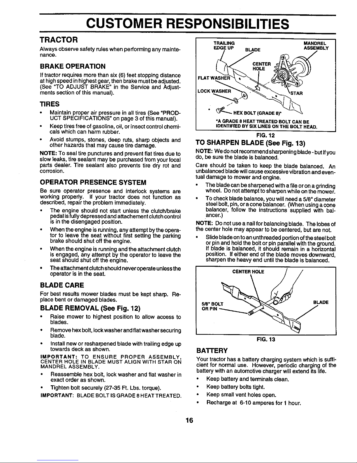
BLADE REMOVAL (See Fig. 12)
• Raise mower to highest position to allow access to
blades.
• Remove hex bolt, Iockwasher and flat washer securing
blade.
• Install new or resharpened blade with trailing edge up
towards deck as shown.
IMPORTANT: TO ENSURE PROPER ASSEMBLY,
CENTER HOLE IN BLADE MUST ALIGN WITH STAR ON
MANDREL ASSEMBLY.
• Reassemble hex bolt, lock washer and flat washer in
exact order as shown.
• Tighten bolt securely (27-35 Ft. Lbs. torque).
IMPORTANT: BLADE BOLT IS GRADE 8 HEATTREATED.
TRAILING
EDGE UP
BLADE
MANDREL
ASSEMBLY
FLAT WASHEI_
LOCK WASHER
HEX BOLT (GRADE 8)*
*A GRADE 8 HEAT TREATED BOLT CAN BE
IDENTIFIED BY SIX LINES ON THE BOLT HEAD.
FIG. 12
TO SHARPEN BLADE (See Fig. 13)
NOTE: We do notrecommend sharpening blade- but ifyou
do, be sure the blade is balanced.
Care should be taken to keep the blade balanced. An
unbalanced blade willcause excessive vibrationand even-
tual damage to mower and engine.
• The blade can be sharpened with a file or on agrinding
wheel. Do not attempt to sharpen while on the mower.
• To check blade balance, you will need a 5/8" diameter
steel bolt, pin,or a cone balancer. (When usingacone
balancer, fellow the instructions supplied with bal-
ancer.)
NOTE: Do not use a nailfor balancing blade. The lobes of
the center hole may appear to be centered, but are not.
• Slide blade on to an unthreaded portionof the steel bolt
or pin and hold the bolt or pin parallel with the ground.
If blade is balanced, it should remain in a horizontal
position. Ifeither end of the blade moves downward,
sharpen the heavy end until the blade is balanced.
CENTER HOLE
5/8" BOLT
BLADE
FIG. 13
BA'n'ERY
Your tractor has a battery charging system which is suffi-
cient for normal use. However, pedodic charging of the
battery with an automotive charger will extend its life.
• Keep battery and terminals clean.
• Keep battery boltstight.
• Keep small vent holes open.
• Recharge at 6-10 amperes for 1 hour.
16
CUSTOMER RESPONSIBILITIES
TO CLEAN BA'I-I'ERY AND TERMINALS
Corrosion and dirt on the battery and terminals can cause
the battery to "leak" power.
• Open battery box door.
• Disconnect BLACK battery cable first then RED bat-
tery cable and remove battery from tractor.
• Rinse the battery with plain water and dry.
• Clean terminals and batterycable ends with wire brush
until bright.
• Coat terminals with grease or petroleum jelly.
• Reinstall battery (See "CONNECT BATTERY" in the
Assembly section of this manual).
V-BELTS
Check V-belts for deterioration and wear after 100 hours
and replace if necessary. The belts are not adjustable.
Replace belts if they begin to slip from wear.
TRANSAXLE COOLING
Keep transaxle free from build-up of dirt and chaff which
can restrict cooling.
ENGINE
LUBRICATION
Only use high quality detergent oil rated with API service
classification SF, SG, or SH. Select the oil's SAE viscosity
grade according to your expected operating temperature.
SAE VISCOSITY GRADES
.30 o .20 _ .10 • 0o 10 _ 20_ 30 °
TEMPERATURE RANGE ANTICIPATED BEFORE NEXT OIL CHANGE
FIG. 14
NOTE: Although multi-viscosity oils (5W30, 10W30 etc.)
improve starting in cold weather, these multi-viscosity oils
will result in increased oil consumption when used above
32°F. Check your engine oil level more frequently to avoid
possible engine damage from running low on oil.
Change the oil after every 25 hours of operation or at least
once a year ifthe tractor isnot used for25 hoursin one year.
Check the crankcase oil level before starting the engine
and after each eight (8) hours of operation. Tighten oilfill
cap/dipstick securely each time you check the oil level.
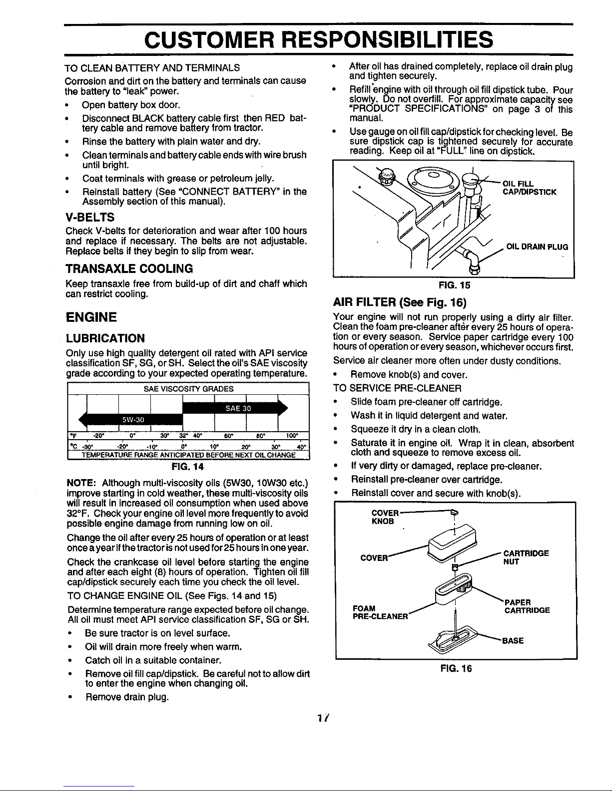
TO CHANGE ENGINE OIL (See Figs. 14 and 15)
Determine temperature range expected before oilchange.
All oil must meet API service classification SF, SG or SH.
• Be sure tractor is on level surface.
Oil will drain more freely when warm.
Catch oil in a suitable container.
Remove oil fill cap/dipstick. Be careful not to allow dirt
to enter the engine when changing oil.
Remove drain plug•
After oil has drained completely, replace oil drain plug
and tighten securely.
Refill'engine with oil through oil fill dipstick tube. Pour
slowly. Do not overfill. For approximate capacity see
PRODUCT SPECIFICATIONS on page 3 of this
manual.
Use gauge on oil fillcap/dipstick for checking level. Be
sure dipstick cap is tightened securely for accurate
reading. Keep oil at "FULL'_ line on dipstick.
7, CAP/DIPSTICK
OIL DRAIN PLUG
FIG. 15
AIR FILTER (See Fig. 16)
Your engine will not run properly using a dirty air filter•
Clean the foam pre-cleaner after every 25 hours ofopera-
tion or every season. Service paper cartridge every 100
hours of operation or every season, whichever occurs first.
Service air cleaner more often under dusty conditions.
• Remove knob(s) and cover.
TO SERVICE PRE-CLEANER
• Slide foam pre-cleaner off cartridge.
• Wash it in liquid detergent and water•
• Squeeze it dry in a clean cloth.
• Saturate it in engine oil. Wrap it in clean, absorbent
cloth and squeeze to remove excess oil.
• If very dirty or damaged, replace pre-cleaner.
• Reinstall pre-cleaner over cartddge.
• Reinstall cover and secure with knob(s).
COVER--
KNOB
COVER
FOAM _ i CARTRIDGE
PRE-CLEANER
_BASE
FIG. 16
1/
 Loading...