

Craftsman 944609040 Owner’s Manual

SEARS
OWNER'S
MANUAL
MODEL NO.
944.609040
I:RrlFTSMANo
Caution:
Read and follow
all Safety Rules
and Instructions
Before Operating
This Equipment
14.5 HP
ELECTRIC START
42" MOWER
6 SPEED TRANSAXLE
LAWN TRACTOR
• Assembly
• Operation
• Customer Responsibilities
• Service and Adjustments
• Repair Parts
Sears Canada, Inc., Toronto, Ontario M5B 2B8
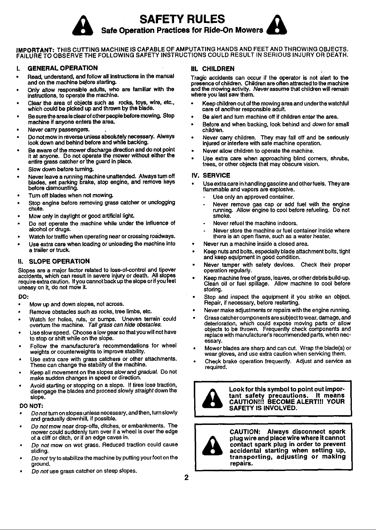
Safe Operation Practices for Ride-On Mowers
SAFETY RULES
IMPORTANT: THIS CUTTING MACHINE IS CAPABLE OF AMPUTATING HANDS AND FEET AND THROWING OBJECTS.
FAILURE TO OBSERVE THE FOLLOWING SAFETY INSTRUCTIONS COULD RESULT IN SERIOUS INJURY OR DEATH.
I. GENERAL OPERATION
• Read,understand,and followall instructionsin the manual
andonthemachinebeforestarting.
• Only allow responsibleadults,who am familiarwith the
instructions,tooperatethe machine.
• Clear the area of objectssuchas rocks, toys,wire, etc.,
whichcouldbe pickedupandthrownbytheblade.
• Besuretheareaisclearofotherpeoplebeforemowing.Stop
machineif anyoneentersthe area.
• Nevercarrypassengers. ,
Donotmowinreverseunlessabsolutelynecessary.Always
lookdownand behindbeforeandwhilebacldng.
• Beawareof the mowerdischargedirectionanddonotpoint
itat anyone. Do not operatethe mowerwithouteitherthe
entiregrasscatcher orthe guardin place.
• Slowdownbefore turning.
Neverleavea running machineunattended.Alwaysturnoff
blades,set parkingbrake, stop engine,and remove keys
beforedismounting.
• Turnoff bladeswhennotmowing.
Stop enginebefore removinggrasscatcher or unclogging
chute.
Mowonlyin daylightor goodartificiallight.
Do not operate the machinewhile underthe influenceof
alcoholordrugs.
Watchfortrafficwhenoperatingnearorcrossingroadways.
• Useextracarewhen loadingor unloadingthemachineinto
a traileror truck.
il. SLOPE OPERATION
Slopes are a major factor related to loss-of-control and tipover
accidents, which can result in severe injury or death. All slopes
require extra caution, ifyou cannot back upthe slope or ifyou feet
uneasy on it, do not mow it.
DO:
• Mow up and down slopes, not across.
• Remove obstacles such as rocks, tree limbs, etc.
• Watch for holes, ruts, or bumps. Uneven terrain could
ovedum the machine. Tall grass can hide obstacles.
• Use slowspeed. Choose a law gear so that you will not have
to stop or shift while on the slope.
• Follow the manufacturer's recommendations for wheel
weights or counterweights to improve stability.
• Use extra care with grass catchers or other attachments.
These can change the stability of the machine.
• Keep all movement on the slopes slow and gradual. Do not
make sudden changes in speed or direction.
• Avoid starting or stopping on a slope. If tires lose traction,
disengage the blades and proceed slowly straight down the
slope.
DO NOT:
• Donottumonslopasunlessnecassary, andthen, tumslowly
and gradually downhill, ifpossible.
• Do not mow near drop-offs, ditches, or embankments. The
mower could suddenly turn over ifa wheel isover the edge
of a cliff or ditch, or if an edge caves in.
• Do not mow on wet grass. Reduced traction could cause
sliding.
Do not try to stabilize the machine by puttingyour footon the
ground.
• Do not use grass catcher on steep slopes.
III. CHILDREN
Tragic accidents can occur if the operator is not alert to the
presence ofchildren. Children are often attracted tothe machine
and the mowing activity. Neverassume that children will remain
where you last saw them.
• Keep children out of the mowing area and under the watchful
care of another responsible adult.
• Be alert and turn machine off if children enter the area.
• Before and when backing, look behind and down for small
children.
• Never carry children. They may fall off and be sedously
injured or interfere with safe machine operation.
Never allow children to operate the machine.
• Use extra care when approaching blind corners, shrubs,
tress, or other objects that may obscure vision.
IV, SERVICE
• Use extra cam inhandling gasoline and other fuels. Theyare
flammable and vapors are explosive.
Use only an approved container.
Never remove gas cap or add fuel with the engine
running. Allow engine to cool before refueling. Do not
smoke.
Never refuel the machine indoors.
Never store the machine or fuel container inside where
there isan open flame, such as a water heater.
• Never run a machine inside a closed area.
• Keep nuts and bolts, especially blade attachment bolts, tight
and keep equipment in good condition.
• Never tamper with safety devices. Check their proper
operation regularly.
• Keep machine free of grass, leaves, orother debris build-up.
Clean oil or fuel spillage. Allow machine to cool before
stodng.
• Stop and inspect the equipment if you strike an object.
Repair, ifnecessary, before restarting.
• Never make adjustments or repairs with the engine running.
Grass catcher components are subjectto wear, damage, and
deterioration, which could expose moving parts or allow
objects to be thrown. Frequently check components and
replace with manufacturer's recommended pads, when nec-
essary.
Mower blades are sharp and can cut. Wrap the blade(s) or
wear gloves, and use extra caution when servicing them.
Check brake operation frequently. Adjust and service as
required.
Look for this symbol to point out impor-
tant safety precautions. It means
CAUTION!H BECOME ALERTH! YOUR
SAFETY IS INVOLVED.
CAUTION: Always disconnect spark
plug wire and place wire where it cannot
contact spark plug in order to prevent
accidental starting when setting up,
transporting, adjusting or making
repairs.
2
CONGRATULATIONS on your purchase of a Sears
Tractor. It has been designed, engineered and manufac-
tured to give you the best possible dependability and
performance.
Should you experience any problem you cannot easily
remedy, please contact your nearest Sears Authorized
Service Centre/Depertment. We have competent, well-
trained technicians and the propertoolstoservice or repair
this tractor.
Please read and retain this manual. The instructionswill
enable you toassemble and maintain yourtractor properly.
Always observe the "SAFETY RULES".
MODEL
NUMBER
i SERIAL
NUMBER
DATEOFPURCHASE
THEMODELANDSERIALNUMBERSWILLBEFOUND
iON A PLATE UNDER THE SEAt.
YOUSHOULDRECORDBOTHSERIALNUMBERAND
DATE OFPURCHASEANDKEEPINASAFEPLACE
FOR FUTURE REFERENCE.
944.609040
MAINTENANCE AGREEMENT
A Sears Maintenance Agreement isavailable onthis prod-
uct. Contact your nearest Sears store for details.
CUSTOMER RESPONSIBILITIES
• Read and observe the safety rules.
Followa regularschedule in maintaining,caringforand
using your tractor.
• Follow the instructionsunder"Customer Responsibili-
ties" and "Storage" sections of this owner's manual.
PRODUCT SPECIFICATIONS
HORSEPOWER: 14.5
GASOLINECAPACITY 1.25GALLONS
ANDTYPE: UNLEADEDREGULAR
OILTYPE (API-SF/SG/SH): SAE 30 (above32"F)
OIL CAPACITY: 3 PINTS
SPARKPLUG: CHAMPION RC12YC
(GAP: .030")
VALVE CLEARANCE: INTAKE: ,003"- .005"
GROUND SPEED (MPH): FORWARD:
TIRE PRESSURE: FRONT: 14 PSI
CHARGING SYSTEM: 3 AMPS BATrERY
BA'I-rERY: AMP/HR: 25
i BLADEBOLTTORQUE:
WARNING: This tractor is equipped with an internal
combustion engine and shouldnot be used on or near any
unimproved forest-covered, brush-covered or grass-cov-
ered land unless the engine's exhaust system is equipped
with a spark arrester meeting applicable local orstate laws
(ifany). If a spark attester isused, it shouldbe maintained
in effective working order by the operator.
A spark arrester for the muffler is available through your
nearest Sears Authorized Service Centre/Department (See
REPAIR PARTS section of this manual).
SAE 5W-30 (below32°F)
EXHAUST: .005"- .007"
1st 1.1
2nd 1.4
3rd 2.2
4th 3.3
5th 4.4
6th 4.9
REVERSE: 1.4
REAR: 12 PSI
5 AMPS HEADLIGHTS
MIN. CCA: 190
CASE SIZE: UIR
27-35 FT. LBS.
3

TABLE OF CONTENTS
]
SAFETY RULES ............................................................ 2
PRODUCT SPECIFICATIONS ...................................... 3
CUSTOMER RESPONSIBILITIES ..................... 3, 14-17
WARRANTY ...................................... ,........................... 4
ASSEMBLY ................................................................ 6-8
OPERATION ............................................................. 9-13
MAINTENANCE SCHEDULE ...................................... 14
LIMITED TWO (2) YEAR WARRANTY ON CRAFTSMAN TRACTOR (RIDING EQUIPMENT)
ForTwo (2) yearsfromdateof purchaseSearsCanada, Inc.willrepairorreplaceat Searsoptionfreeofchargepartswhichare
defectiveas a resultofmatadal orwodo'nanship.
FULL ONE (1) YEAR WARRANTY ON BATTERY
For One (1) year from date of purchase,if any batteryincludedwiththis ddingequipmentprovesdefectivein materialor
workmanshipandourtestingdeterminesthebatterywillnotholda charge,Searswillreplacethe batteryatnocharge.
COMMERCIAL OR RENTAL USE
Warrantyon RidingEquipmentusedforcommercialor rentalpurposesisIimitedtoninety(90) days.
This Warranty does NOT cover:
1. Pre-dellverysot-up.
2. Tire replacement or repair caused by punctures from outside objects (such as nails,thorns, stumps, or glass).
3. ExpendableItems which become worn during normal usa, euch as blades, spark plug, air cleaners and belts.
4. Repairs necessary because of operator abuse or negligence, Including damaged Jackshaftor mandrel and the
failure to operate and maintain the equlp_nentaccordingto the Instructions contained Inthe Owner's Manual.
5. InHome service.
SERVICE AND ADJUSTMENTS ............................ 18-22
STORAGE ................................................................... 23
TROUBLESHOOTING ..................................... ,......24.25
REPAIR PARTS - TRACTOR ................................. 28-43
REPAIR PARTS - ENGINE .................................... 44-49
PARTS ORDERING/SERVICE ................ BACK COVER
I
Warrantyserviceis available by ratumingthe CraftsmanRidingEquipmentto the nearestSearsServiceCantre/Departmantin
Canada. Thiswarrantyappliesonlywhilethis productisin usein Canada.
This warrantyis in additionto any statutory warrantyand does notexclude or limit legal rightsyou may have but shallrun
concurrentlywithapplicable provinciallegislation.Furthermore,some proVincesdo NOT allowlimitationon howlongan implied
warrantywill lastsothe abovelimitationsmaynotapply to you.
SEARS CANADA, INC., TORONTO, ONTARIO M5B 2B8
4
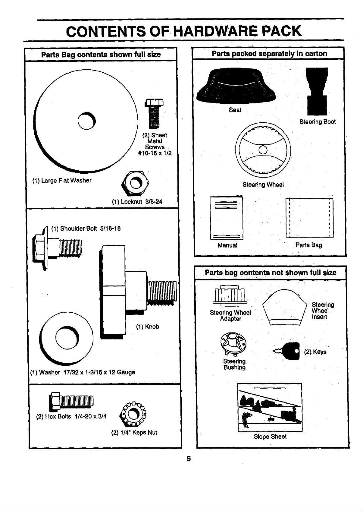
CONTENTS OF HARDWARE PACK
=
Parts Bag contents shown full size
i i
i
Parts packed separately in carton
Seat
Steedng Boot
(1) Large Flat Washer
(1) Locknut 318-24
(1) Shoulder Bolt 5116-18
mm
©
(1) Washer 17/32 x 1-3/16 x 12 Gauge
i I
i i i
(1) Knob
Steedng Wheel
ii
: I
li [
I I
Manual
Parts bag contents not shown full size
r_ _'2_%'_ Steedng
Steering Wheel Wheel
Adapter _ Insert
_ (2) Keys
Steering
Bushing
Parts Bag
(2) Hex Bolts 1/4-20 × 3/4
(2) 1/4" Keps Nut
Slope Sheet
5
ASSEMBLY
Your new tractor has been assembled at the factory with exception of those parts left unassembled for shipping purposes.
To ensure safe and proper operation of your tractor all parts and hardware you assemble must betightened securely. Use
the correct tools as necessary to insure proper tightness.
TOOLS REQUIRED FOR ASSEMBLY
A socket wrench set will make assembly easier. Standard
wrench sizes are listed.
(1) 5/16" wrench Phillips Screwddver
(2) 7/16" wrenches Tire pressure gauge
(1) 1/2" wrench Utility knife
(1) 9/16" wrench
When right or left hand is mentioned in this manual, it
means when you are in the operating position (seated
behind the steedng wheel).
TO REMOVETRACTOR FROM CARTON
UNPACK CARTON
• Remove all accessible loose parts and parts cartons
from carton (See page 6).
• Cut,from top to bottom, along lines on all four corners
ofcarton, and lay panels flat.
• Check for any additional loose parts or cartons and
remove.
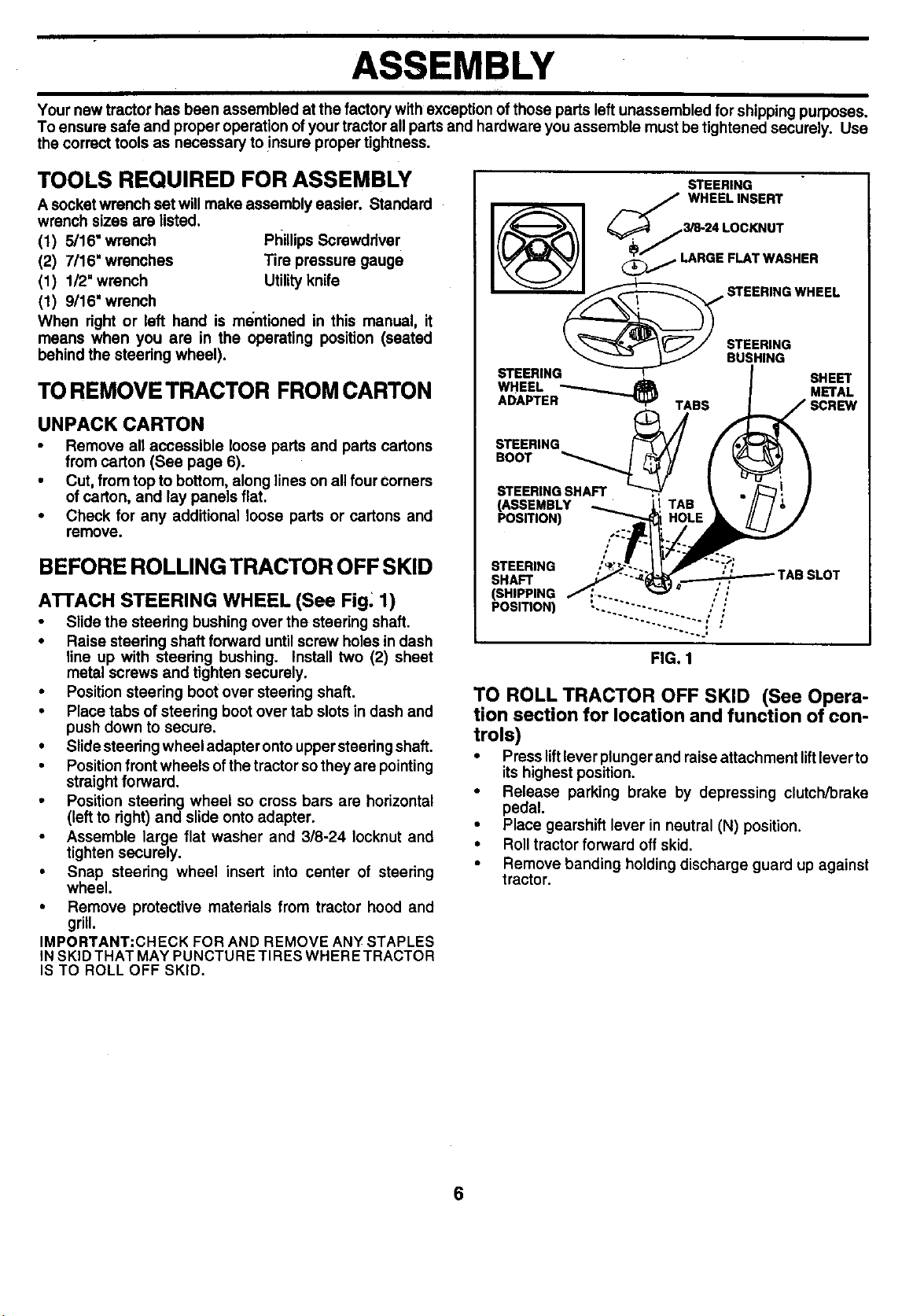
BEFORE ROLLING TRACTOR OFF SKID
ATTACH STEERING WHEEL (See Fig. 1)
• Slide the steering bushing over the steering shaft.
• Raise steering shaft forward until screw holes in dash
line up with steering bushing. Install two (2) sheet
metal screws and tighten securely.
• Position steering boot over steering shaft.
• Place tabs of steering boot over tab slots in dash and
push down to secure.
• Slidesteedng wheel adapter onto uppersteering shaft.
• Positionfrontwheels of the tractorso they are pointing
straight forward.
• Position steering wheel so cross bars are horizontal
(left to right) and slide onto adapter.
• Assemble large flat washer and 3/8-24 Iocknut and
tighten securely.
• Snap steering wheel insert into center of steering
wheel.
• Remove protective materials from tractor hood and
grill.
IMPORTANT:CHECK FOR AND REMOVE ANY STAPLES
IN SKID THAT MAY PUNCTURE TIRES WHERE TRACTOR
IS TO ROLL OFF SKID.
STEERING
/_/ WHEELINSERT
_ \_// STEERING
STEERING_ BUSHING SHEET
STEERING
(ASSEMBLY
POSITION)
STEERING
SHAFT
(SHIPPING
POSITION)
FIG. 1
TO ROLL TRACTOR OFF SKID (See Opera-
tion section for location and function of con-
trols)
• Press liftlever plunger and raise attachment liftleverto
itshighest position.
• Release parking brake by depressing clutch/brake
pedal.
• Place gearshift lever in neutral (N) position.
• Roll tractor forward off skid.
• Remove banding holding discharge guard up against
tractor.
6
ASSEMBLY
HOW TO SET UP YOUR TRACTOR
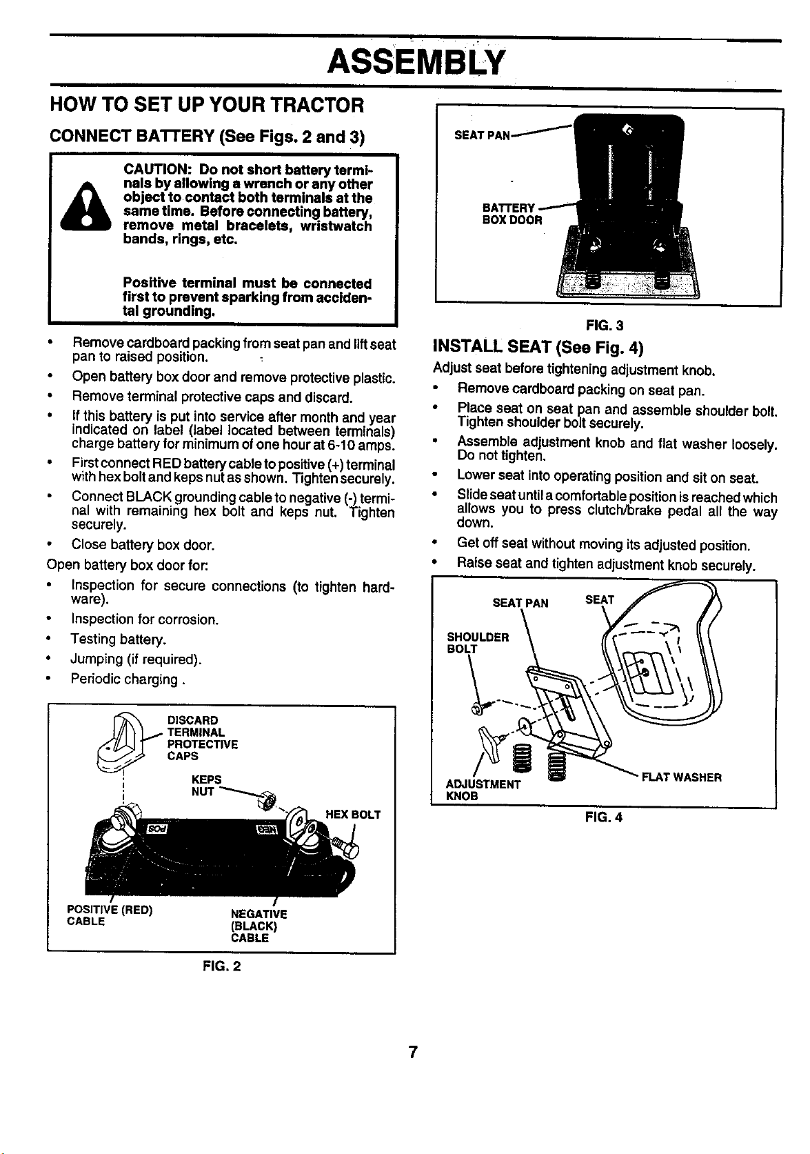
CONNECT BATI'ERY (See Figs. 2 and 3)
CAUTION: Do not short battery termi-
nals by allowing a wrench or any other
object to contact both terminals at the
same time. Before connecting battery,
remove metal bracelets, wristwatch
bands, rings, etc.
Positive terminal must be connected
first to prevent sparking from acciden-
tal grounding.
• Remove cardboard packing from seat pan and lift seat
pan to raised position.
Open battery box door and remove protective plastic.
• Remove terminal protective caps and discard.
• Ifthis battery is put into service after month and year
indicated on label (label located between terminals)
charge battery for minimum of one hour at 6-10 amps.
• Firstconnect RED battery cable to positive (+) terminal
with hex bolt and keps nutas shown. Tighten securely.
Connect BLACK grounding cable to negative (-) termi-
nal with remaining hex bolt and keps nut. Tighten
securely.
• Close battery box door,
Open battery box door for:
• Inspection for secure connections (to tighten hard-
ware).
• Inspection for corrosion.
• Testing battery.
• Jumping (if required).
Periodic charging.
BOXDOOR
FIG. 3
INSTALL SEAT (See Fig. 4)
Adjust seat before tightening adjustment knob.
• Remove cardboard packing on seat pan.
• Place seat on seat pan and assemble shoulder bolt.
Tighten shoulder bolt securely.
• Assemble adjustment knob and flat washer loosely.
Do not tighten.
• Lower seat intooperating positionand sit on seat.
• Slide seat untila comfortable position is reached which
allows you to press clutch/brake pedal all the way
down.
• Get off seat without moving its adjusted position.
• Raise seat and tighten adjustment knob securely.
TERMINAL
PROTECTIVE
_ ISCARD
; KEPS
; NUT _._
POSITIVE (RED) NEGATIVE
CABLE (BLACK)
CAPS
CABLE
FIG, 2
HEX BOLT
" FLAT WASHER
KNOB
FIG. 4
7
ASSEMBLY
CHECK TIRE PRESSURE
The tiredon yourtractor were ovednflated at the factory for
shipping purposes. Correct tire pressure is important for
best cutting performance.
• Reduce tire pressure to PSI shown in "PRODUCT
SPECIFICATIONS" on I_g¢_ 3 of this manual.
CHECK DECK LEVEM_E¥_
For best cutting results, mower Ii_g_'should be properly
leveled. See "TO LEVEL MOWER HOUSING" in the
Service and Adjustments section of this manual.
CHECK FOR PROPER 'POSITION OF ALL
BELTS
See the figures that are shown for replacing motion and
mower blade ddve belts in the Service and Adjustments
section of this manual. Verify that the belts are routed
correctly.
CHECK BRAKE SYSTEM
After you learn how to operate your tractor, check to see
that the brake is properly adjusted. See "TO ADJUST
BRAKE" in the Service and Adjustments section of this
manual.
I
,/CHECKLIST
BEFORE YOU OPERATE AND ENJOY YOUR NEW
TRACTOR, WE WISH TOASSURE THAT YOU RECEIVE
THE BEST PERFORMANCE AND SATISFACTION FROM
THIS QUALITY PRODUCT.
PLEASE REVIEW THE FOLLOWING CHECKLIST:
/ All assembly instructions have been completed.
/ No remaining loose parts in carton.
,/ Battery is properly prepared and charged. (Minimum
1 hour at 6 amps).
,/ Seat is adjusted comfortably and tightened securely.
/ All tires are propedy inflated. (For shipping purposes,
the tires were overmflated at the factory).
,/ Be sure mower deck is properly leveled side-to-side/
front-to-rear for best cutting results. (Tires must be
properly inflated for leveling).
,/ Check mowerand ddve belts. Be sure they are routed
properly around pulleys and inside all belt keepers.
,/ Check wiring. See that all connections are stillsecure
and wires are properly clamped.
WHILE LEARNING HOW TO USE YOUR TRACTOR, PAY
EXTRA ATTENTION TO THE FOLLOWING IMPORTANT
ITEMS:
/ Engine oil is at proper level.
,/ Fuel tank is filled with fresh, clean, regular unleaded
gasoline.
/ Become familiar with all controls - their location and
function. Operate them before you start the engine.
/ Be sure brake system is in safe operating condition.
8
OPERATION
These symbols may appear on your produ_ or in literature supplied with the produ_, Leam and understand their meaning.
BATFERY CAUTION OR REVERSE FORWARD FAST SLOW
WARNING
FUEL CHOKE MOWER HEIGHT PARKING BRAKE UNLOCKED MOWER LIFT
LOCKED
N H L
ATTACHMENT REVERSE
CLUTCH ENGAGED
ATTACHMENT
IGNITION CLUTCH DISENGAGED (SEE SAFETY RULES SECTION)
NEUTRAL HIGH LOW
KEEP AREA CLEAR SLOPE HAZARDS
PARKING BRAKE
DANGER, KEEP HANDS AND FEET AWAY
FREE WHEEL
(AutomaticModels only)
9
OPERATION
I I I
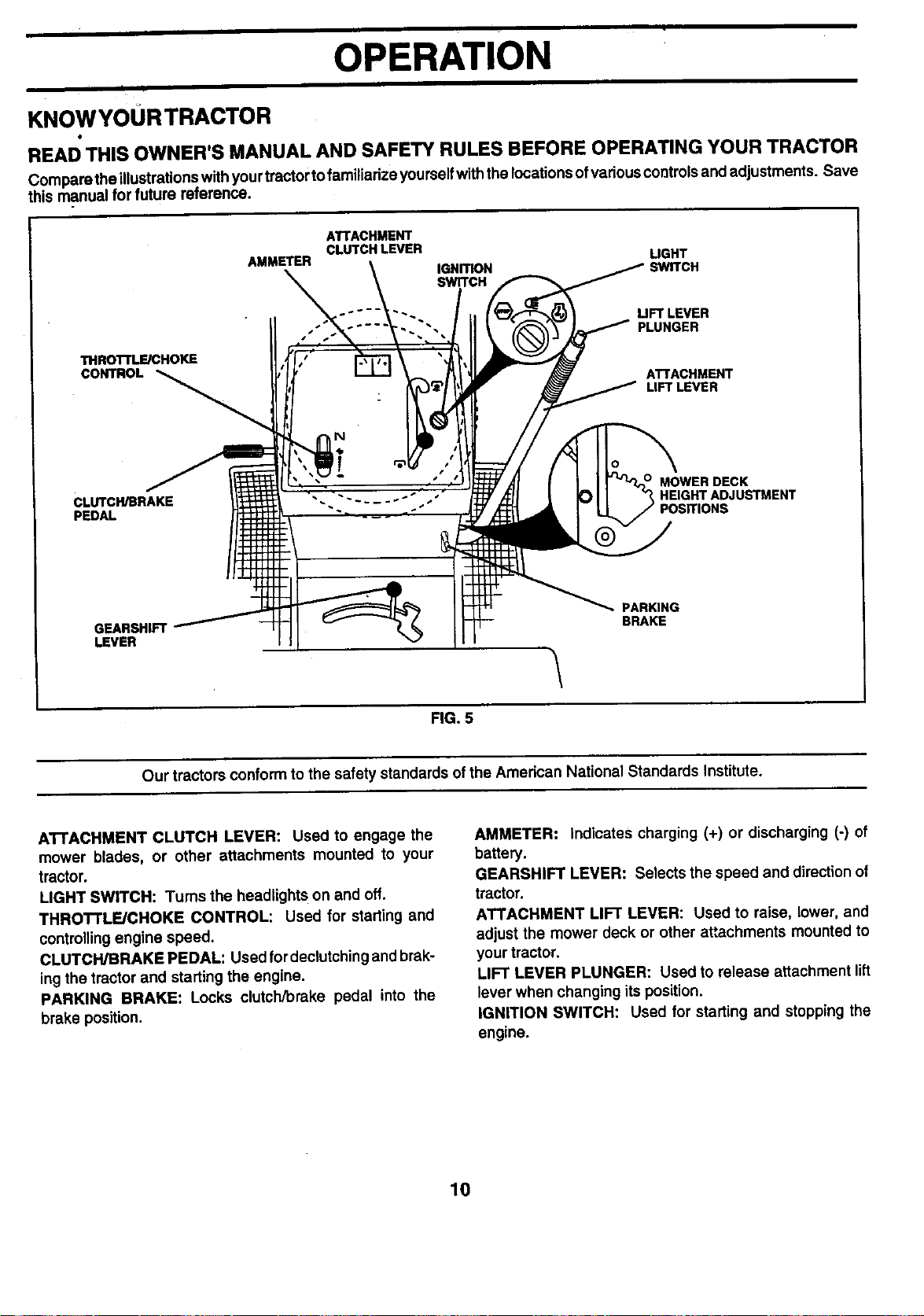
KNOWYOURTRACTOR
READ THIS OWNER'S MANUAL AND SAFETY RULES BEFORE OPERATING YOUR TRACTOR
Compare theillustrationswith yourtractor to familiarize yourselfwiththe locations ofvarious controlsand adjustments. Save
this manual for future reference.
ATTACHMENT
AMMETER IGNITION ;WITCH
CLUTCH LEVER LIGHT
SWITCH
UFT LEVER
PLUNGER
THROTFLE/CHOKE
CONTROL
CLUTCH/BRAKE
PEDAL
GEARSHIFT
LEVER
Our tractors conform to the safety standards ofthe American National Standards Institute.
ATTACHMENT
LIFT LEVER
HEIGHT ADJUSTMENT
PARKING
BRAKE
FIG. 5
ATTACHMENT CLUTCH LEVER: Used to engage the
mower blades, or other attachments mounted to your
tractor.
LIGHT SWITCH: Turns the headlights on and off.
THROTTLE/CHOKE CONTROL: Used for starting and
controllingengine speed.
CLUTCH/BRAKE PEDAL: Used fordeclutching and brak-
ing the tractor and startingthe engine.
PARKING BRAKE: Locks clutch/brake pedal into the
brake position.
AMMETER: Indicates charging (+) or discharging (-) of
battery.
GEARSHIFT LEVER: Selects the speed and direction of
tractor.
ATTACHMENT LIFT LEVER: Used to raise, lower, and
adjust the mower deck or other a_achments mounted to
your tractor.
LIFT LEVER PLUNGER: Used to release attachment lift
lever when changing its position.
IGNITION SWITCH: Used for starting and stopping the
engine.
10
OPERATION
The operation of any tractor can result In foreign objects thrown into the eyes, which
can result in severe eye damage. Always wear safety glasses or eye shields while
operating your tractor orperforming any adjustments or repairs. We recommend awide
vision safety mask over spectacles or standard safety glasses.
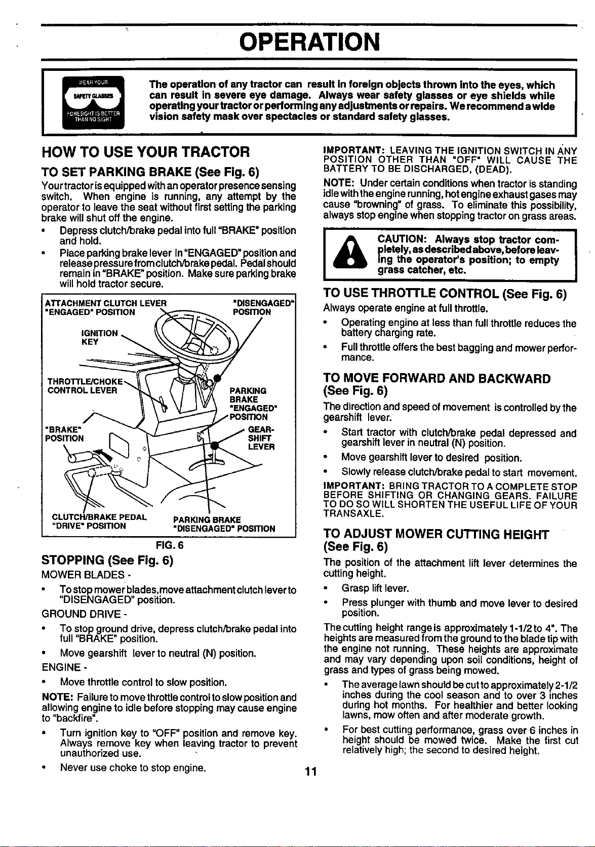
HOW TO USE YOUR TRACTOR
TO SET PARKING BRAKE (See Fig. 6)
Yourtractor isequipped withan operator presence sensing
switch. When engine is running, any attempt by the
operator to leave the seat without first setting the parking
brake will shut off the engine.
• Depress clutch/brake pedal into full "BRAKE" position
and hold.
• Place parking brake lever in"ENGAGED" positionand
release pressure fromclutch/brake pedal. Pedal should
remain in "BRAKE" position. Make sure parking brake
will hold tractor secure.
ATTACHMENT CLUTCH LEVER
"ENGAGED" POSITION
IGNITION
KEY
THROTTLE/CHOKE,.,
CONTROL LEVER
"BRAKE" GEAR-
POSITION SHIFT
CLUTCH/BRAKE PEDAL
"DRIVE"POSmON
PARKING BRAKE
"DISENGAGED"POSmON
FIG. 6
STOPPING (See Fig. 6)
MOWER BLADES -
• To stop mower blades,move attachment clutchleverto
"DISENGAGED" position.
GROUND DRIVE -
• To stop ground drive, depress clutch/brake pedal into
full "BRAKE" position.
• Move gearshift lever to neutral (N) position.
ENGINE -
• Move throttle control to slow position.
NOTE: Failure to move throttle control to slow position and
allowing engine to idle before stopping may cause engine
to "backfire".
• Turn ignition key to "OFF" position and remove key.
Always remove key when leaving tractor to prevent
unauthorized use.
Never use choke to stop engine.
"DISENGAGED"
PosmoN
PARING
BRAKE
"ENGAGED"
LEVER
IMPORTANT: LEAVING THE IGNITION SWITCH IN/_NY
POSITION OTHER THAN "OFF" WILL CAUSE THE
BATTERY TO BE DISCHARGED, (DEAD).
NOTE: Under certain conditions when tractor is standing
idlewiththe engine running, hotengine exhaust gases may
cause "browning" of grass. To eliminate this possibility,
always stop engine when stopping tractor on grass areas.
pletely, as descr bed above, before leav-
I& CAUTION: Always stop tractor com-
TO USE THRO'n'LE CONTROL (See Fig. 6)
Always operate engine at full throttle.
• Operating engine at less than fullthrottle reduces the
battery charging rate.
• Full throttle offersthe best bagging and mower perfor-
mance.
ing the operator's position; to empty
grass catcher, etc.
TO MOVE FORWARD AND BACKWARD
(See Fig. 6)
The directionand speed of movement is controlled bythe
gearshift lever.
• Start tractor with clutch/brake pedal depressed and
gearshift lever in neutral (N) position.
• Move gearshift lever to desired position.
• Slowly release clutch/brake pedal to start movement.
IMPORTANT: BRING TRACTOR TO A COMPLETE STOP
BEFORE SHIFTING OR CHANGING GEARS. FAILURE
TO DO SO WILL SHORTEN THE USEFUL LIFE OF YOUR
TRANSAXLE.
TO ADJUST MOWER CUTTING HEIGHT
(See Fig. 6)
The position of the attachment lift lever determines the
cutting height.
• Grasp lift lever.
• Press plunger with thumb and move lever to desired
position.
The cutting height range is approximately 1-1/2 to 4". The
heights are measured from the groundto the blade tip with
the engine not running. These heights are approximate
and may vary depending upon soil conditions, height of
grass and types of grass being mowed.
The average lawn shouldbe cuttoapproximately 2-1/2
inches during the cool season and to over 3 inches
during hot months. For healthier and better looking
lawns, mow often and after moderate growth.
• For best cutting performance, grass over 6 inches in
height should be mowed twice. Make the first cut
relatively high; the second to desired height.
11
OPERATION
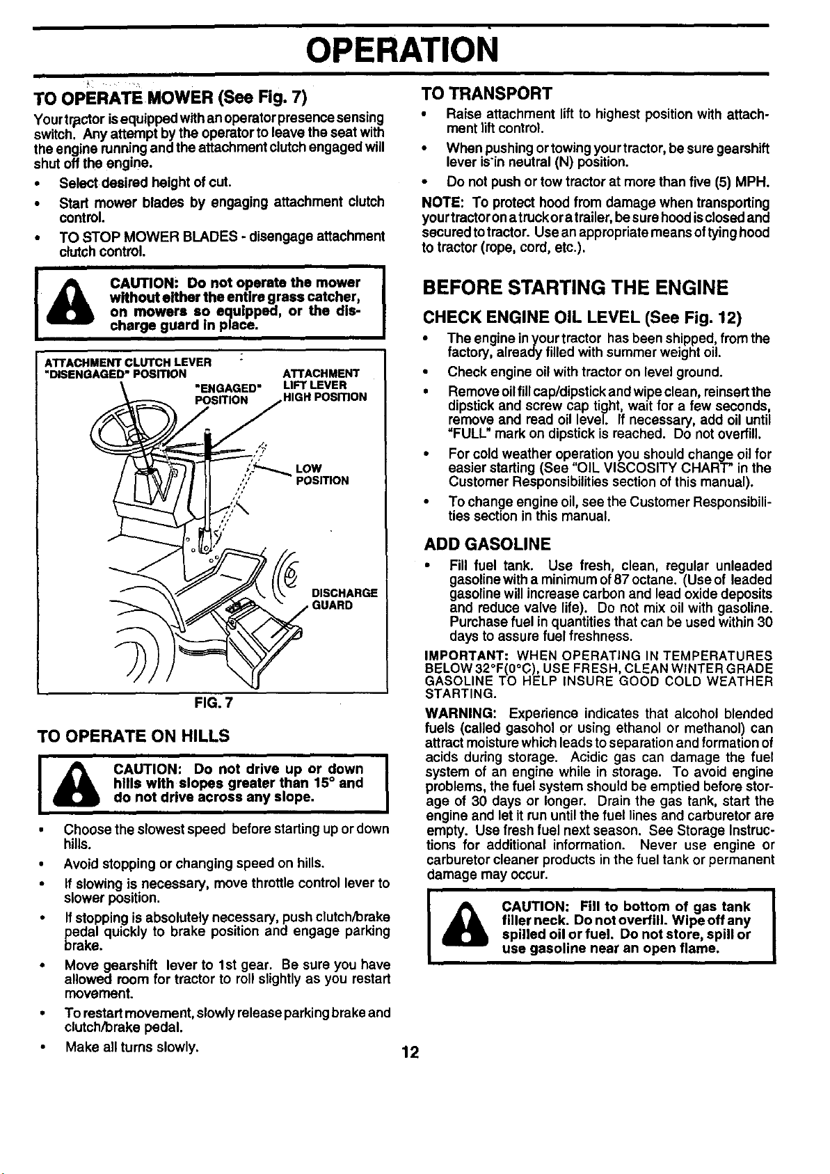
TO OPERATE MOWER (See Fig. 7) TO TRANSPORT
Yourtractor isequipped withan operator presence sensing
switch. Any attempt by the operator to leave the seat with
the engine running and the attachment clutch engaged will
shut off the engine.
• Select desired height of cut.
• Start mower blades by engaging attachment clutch
control.
• TO STOP MOWER BLADES - disengage attachment
clutch control.
• Raise attachment lift to highest position with attach-
ment tilt control.
• When pushing or towingyourtractor, be sure gearshift
lever isin neutral (N) position.
• Do not pushor tow tractor at more than five (5) MPH.
NOTE: To protect hood from damage when transporting
yourtractorona truckor atrailer, besure hoodisclosedand
secured totractor. Use an appropriate meansof tyinghood
to tractor (rope, cord, etc.).
CAUTION: Do not operate the mower
without either the entire grass catcher,
I&
ATTACHMENT CLUTCHLEVER :
"_SENGAGED'POSmON
TO OPERATE ON HILLS
I
Choose the slowest speed before starting up or down
hills.
Avoid stopping or changing speed on hills.
If slowing is necessary, move throttle control lever to
slower position.
Ifstopping isabsolutely necessary, pushclutch/brake
pedal quickly to brake position and engage parking
brake.
Move gearshift lever to 1st gear. Be sure you have
allowed room for tractor to roll slightly as you restart
movement.
To restart movement, slowly release parking brake and
clutch/brake pedal.
• Make all turns slowly. 12
on mowers so equipped, or the dis-
charge guard in place.
ATTACHMENT
"ENGAGED"
POSITION
FIG. 7
hills with slopes greater than 15° and
CAUTION: Do not drive up or down
do not drive across any slope.
LIFT LEVER
HIGH POSITION
DISCHARGE
BEFORE STARTING THE ENGINE
CHECK ENGINE OIL LEVEL (See Fig. 12)
• The engine inyour tractor has been shipped, from the
factory, already filled with summer weight oil.
• Check engine oil with tractor on level ground.
• Remove oilfill cap/dipstick and wipe clean, reinsertthe
dipstick and screw cap tight, wait for a few seconds,
remove and read oil level If necessary, add oil until
"FULL" mark on dipstick is reached. Do notoverfill.
• For cold weather operation you should change oil for
easier starting (See "OIL VISCOSITY CHART" in the
Customer Responsibilities section of this manual).
• To change engine oil, see the Customer Responsibili-
ties section in this manual.
ADD GASOLINE
• Fill fuel tank. Use fresh, clean, regular unleaded
gasoline with a minimum of 87 octane. (Use of leaded
gasoline will increase carbon and lead oxide deposits
and reduce valve life). Do not mix oil with gasoline.
Purchase fuel in quantities that can be used within 30
days to assure fuel freshness.
IMPORTANT: WHEN OPERATING IN TEMPERATURES
BELOW 32°F(0°C), USE FRESH, CLEAN WINTER GRADE
GASOLINE TO HELP INSURE GOOD COLD WEATHER
STARTING.
WARNING: Experience indicates that alcohol blended
fuels (called gasohol or using ethanol or methanol) can
attract moisturewhich leads to separation and formation of
acids during storage. Acidic gas can damage the fuel
system of an engine while in storage. To avoid engine
problems, the fuel system should be emptied before stor-
age of 30 days or longer. Drain the gas tank, start the
engine and let it run untilthe fuel lines and carburetor are
empty. Use fresh fuel next season. See Storage Instruc-
tions for additional information. Never use engine or
carburetor cleaner products in the fuel tank or permanent
damage may occur.
filler neck. Do not overfill. Wipe off any
I & CAUTION: Fill to bottom of gas tank I
spilled oil or fuel. Do not store, spill or
use gasoline near an open flame.
I
I
ill i
OPERATION
TO START ENGINE (See Fig. 6)
When starting the engine for the first time or if the engine
has run out of fuel, itwill take extra cranking time to move
fuel from the tank to the engine.
• Sit on seat in operating position, depress clutch/brake
pedal and set parking brake.
• Place gear shift lever in neutral (N) position.
• Move attachment clutch to =DISENGAGED" position.
• Move throttle control to choke position.
NOTE: Before starting, read the warm and cold starting
procedures below.
• Insertkeyintoignitionandturn keyclockwiseto "START"
position and release key as soon as engine starts. Do
not runstarter continuously for more than fifteen sec-
onds per minute. If the engine does not start after
several attempts, move throttlecontrol to fast position,
wait a few minutes and try again. Ifengine still does not
start, move the throttle control back to the choke
position and retry.
WARM WEATHER STARTING (50° F and above)
• When engine starts, move the throttlecontroltothe fast
position.
• The attachments and ground ddve can now be used. If
the engine does notaccept the load, restartthe engine
and allow itto warm up for one minute usingthe choke
as described above,
COLD WEATHER STARTING ( 50° F and below)
• When engine starts, allowengineto runwiththethrottle
control in the choke position until the engine runs
roughly,then move throttle controltofast position.This
may require an engine warm-up period from several
seconds to several minutes, depending on the tem-
perature.
• The attachments can also be used duringthe engine
warm-up period.
NOTE: If at a high altitude (above 3000 feet) or in cold
temperatures (below 32 F) the carburetor fuel mixturemay
need to be adjusted for best engine performance. See "TO
ADJUST CARBURETOR" inthe Service and Adjustments
section of this manual.
MOWING TIPS
• Tire chains cannot be used when the mower housing
isattached to tractor.
• Mower should be properly leveled for best mowing
performance. See "TO LEVEL MOWER HOUSING" in
the Service and Adjustments section ofthis manual.
• The left hand side of mower should be used for trim-
ming.
• Drive so that clippings are discharged onto the area
that has been cut. Have the cutarea tothe rightof the
machine. This will result in a more even distributionof
clippings and more uniform cutting.
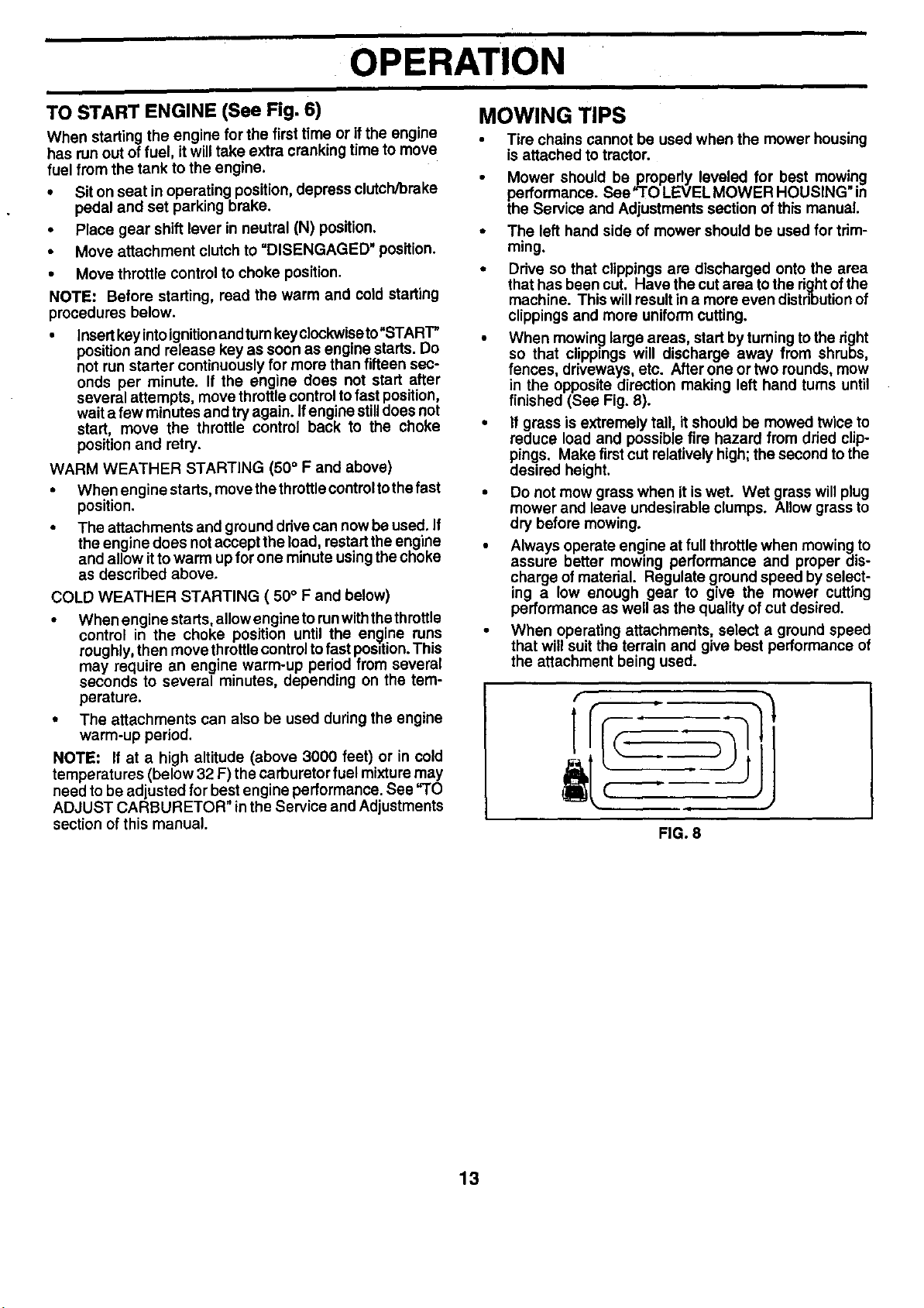
• When mowing large areas, start byturning to the dght
so that clippings will discharge away from shrubs
fences, driveways, etc. After one ortwo rounds, mow
in the opposite direction making left hand turns until
finished (See Fig. 8).
• If grass is extremely tall, itshould be mowed twice to
reduce load and possible fire hazard fromdried clip-
pings. Make first cut relatively high; the second tothe
desired height.
• Do not mow grass when it is wet. Wet grass willplug
mower and leave undesirable clumps. Allow grass to
dry before mowing.
• Always operate engine at full throttle when mowing to
assure better mowing performance and proper dis-
charge of material. Regulate ground speed by select-
ing a low enough gear to give the mower cutting
performance as well as the quality of cut desired.
• When operating attachments, select a ground speed
that will suit the terrain and give best performance of
the attachment being used.
FIG. 8
13
cuSTOMER RESPONSIBILITIES
AS YOU COMPLETE ._j.__j_._-._._..___-_'_4,_._'4. '_-_"/.._c_._'_ -
FILL IN DATESsERVICE _._f_:
Check Brake Operation _1
Check Tire Pressure
Check Operator Presence and
T Interlock Systems
Check for Loose Fasteners I_:, I_
Lubrication Chart l##
T Check Battery Level
A Sharpen/Replace Mower Blades i4
R Clean Battery and Terminals V'
Check Transaxle Cooling
Adjust Blade Belt(s) Tension I_s
Adjust Motion Drive Belt(s) Tension V's
Check Engine Oil Level I_
Change Engine Oil _1.2,3
E Clean Air Filter _:
Clean Air Screen
G Inspect Muffler/Spark Arrester li_
Replace equipped)
NI Oil Rlter (if Ik#_1,2
E clean Engine Cooling Fins V'=
Replace Spark Plug I_ I_
Replace Air Filter Paper Cartddge
Replace Fuel Filter I_
1 - Change more often when operating under a heavy load or in high ambient temperatures.
2 o Service more often when operating in dirty or dusty conditions.
3 - If equipped with oil filter, change oil every 50 hours.
4 - Replace blades more often when mowing in sandy soil.
GENERAL RECOMMENDATIONS
The warranty on thistractor does not cover itemsthat have
been subjected to operator abuse or negligence. To
receive full value from the warranty, operator must main-
tain tractor as instructed in this manual.
Some adjustments will need to be made periodically to
properly maintain your tractor.
All adjustments in the Service and Adjustments section of
this manual should be checked at least once each season.
Once a year you should replace the spark plug, clean (_
or replace air filter, and check blades and belts for CLUTCH
wear. A new spark plug and clean air filter assure PIVOT(S)
proper air-fuel mixture and helpyour engine runbetter
and last longer,
®
@
BEARING ZERK
IBm
5 - If equipped with adjustable system.
6 - Not required if equipped with maintenance-f ree battery.
7 - Tighten front axle pivot bolt to 35 ft.-los, maximum.
Do not overtighten.
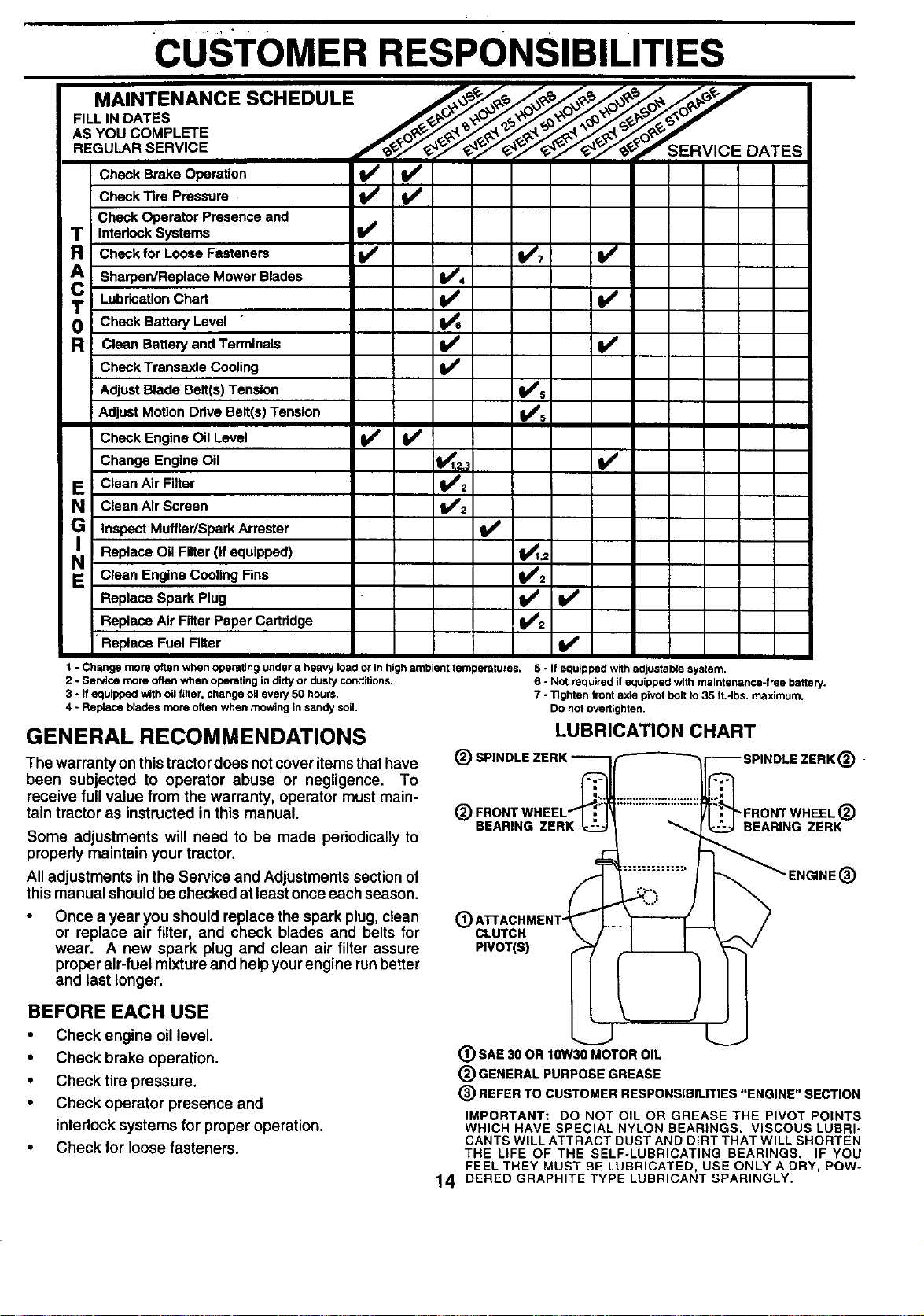
LUBRICATION CHART
.
"FRONT WHEEL ®
BEARING ZERK
®
BEFORE EACH USE
• Check engine oil level.
• Check brake operation.
• Check tire pressure.
• Check operator presence and
interlocksystems for proper operation.
• Check for loose fasteners.
® SAE 30 OR 10W30 MOTOR OIL
® GENERAL PURPOSE GREASE
® REFER TO CUSTOMER RESPONSIBILITIES "ENGINE" SECTION
IMPORTANT: DO NOT OIL OR GREASE THE PIVOT POINTS
WHICH HAVE SPECIAL NYLON BEARINGS. VISCOUS LUBRI-
CANTS WILL ATTRACT DUST AND DIRT THAT WILL SHORTEN
THE LIFE OF THE SELF-LUBRICATING BEARINGS. IF YOU
FEEL THEY MUST BE LUBRICATED, USE ONLY A DRY, POW-
14 DERED GRAPHITE TYPE LUBRICANT SPARINGLY.

CUSTOMER RESPONSIBILITIES
TRACTOR
Always observe safety rules when performingany mainte-
nance.
BRAKE OPERATION
Iftractor requires more than six (6) feet stopping distance
at highspeed in highest gear, then brake mustbeadjusted.
(See "TO ADJUST BRAKE" in the Service and Adjust-
ments section of this manual).
TIRES
• Maintain proper air pressure in all tires (See =PROD-
UCT SPECIFICATIONS" on page 3 of this manual).
• Keep tiresfree ofgasoline, oil, or insectcontrolchemi-
cals which can harm rubber.
• Avoid stumps, stones; deep ruts, sharp objects and
other hazards that may cause tire damage.
NOTE: To seal tire punctures and prevent flat tires due to
slow leaks, tiresealant may be purchased from your local
parts dealer. Tire sealant also prevents tire dry rot and
corrosion.
OPERATOR PRESENCE SYSTEM
Be sure operator presence and interlock systems are
working properly. If your tractor does not function as
described, repair the problem immediately.
• The engine should not start unless the clutch/brake
pedal is fully depressed and attachement clutch con-
trol is in the disengaged position.
• When the engine isrunning, any attempt bythe opera-
tor to leave the seat without first setting the parking
brake should shut off the engine.
• When the engine is running and the attachment clutch
is engaged, any attempt by the operator to leave the
seat should shut off the engine.
• The attachment clutch should never operate unless
the operator is in the seat.
TRAILING MANDREL
EDGE UP ASSEMBLY
FLAT WASHER
LOCK WASHER
*A GRADES HEAT TREATED BOLT CAN BE
IDENTIRED BY SIX LINES ON THE BOLT HEAD.
BLADE
STAR
HEX BOLT (GRADE 8)*
FIG. 9
TO SHARPEN BLADE (See Fig. X2)
NOTE:We donotrecommendsharpeningblade-butifyou
do, be surethe bladeisbalanced.
Care should be taken to keep the blade balanced. An
unbalanced blade will cause excessive vibration and even-
tual damage to mower and engine.
• The blade can be sharpened with a file or on a gdnding
wheel. Do not attempt to sharpen while on the mower.
• To check blade balance, you will need a 5/8" diameter
steel bolt, pin, or a cone balancer. (When using a cone
balancer, follow the instructions supplied with bal-
ancer.)
NOTE: Do not use a nail for balancing blade. The lobes of
the center hole may appear to be centered, but are not.
• Slide blade on to an unthreaded portion ofthe steel bolt
or pin and hold the bolt or pin parallel with the ground.
If blade is balanced, it should remain in a horizontal
position. If either end of the blade moves downward,
sharpen the heavy end until the blade is balanced.
BLADE CARE
For best results mower blades must be kept sharp. Re-
place bent or damaged blades,
BLADE REMOVAL (See Fig. 9-)
• Raise mower to highest position to allow access to
blades.
• Remove hex bolt, lock washer and flatwasher secur-
ing blade.
• Install new or resharpened blade with trailingedge up
towards deck as shown.
IMPORTANT: TO ENSURE PROPER ASSEMBLY,
CENTER HOLEIN BLADE MUSTALIGN WITH STAR ON
MANDRELASSEMBLY.
Reassemble hex bolt, lock washer and flat washer in
exact order as shown.
• Tighten bolt securely (27-35 Ft. Lbs. torque).
IMPORTANT: BLADE BOLTIS GRADE 8 HEATTREATED.
CENTER HOLE _// /
5/8" BO_ BLADE
OR PIN
BATTERY FIG. 10
Your tractor has a battery charging system which is suffi-
cient for normal use. However, periodic charging of the
battery with an automotive charger will extend its life.
• Keep battery and terminals clean.
• Keep battery bolts tight.
Keep small vent holes open.
• Recharge at 6-10 amperes for 1 hour.
15
CUSTOMER RESPONSIBILITIES
TO CLEAN BA'I-rERY AND TERMINALS
Corrosion and dirtonthe battery and terminals can cause the
battery to "leak" power.
• Open battery box door.
• DisconnectBLACKbatterycablefirst thenRED battery
cable and remove battery from tractor.
• Rinse the battery with plain water and dry.
• Clean terminals and battery cable ends with wire brush
until bdght.
• Coat terminals with grease or petroleum jelly.
• Reinstall battery (See "CONNECT BATTERY" in the
Assembly section of this manual).
V-BELTS
Check V-belts for deterioration and wear after 100 hoursof
operation and replace if necessary. The belts are not
adjustable. Replace belts if they begin to slip from wear.
TRANSAXLE COOLING
Keep transaxle free from build-up of dirt and chaff which
can restrict cooling.
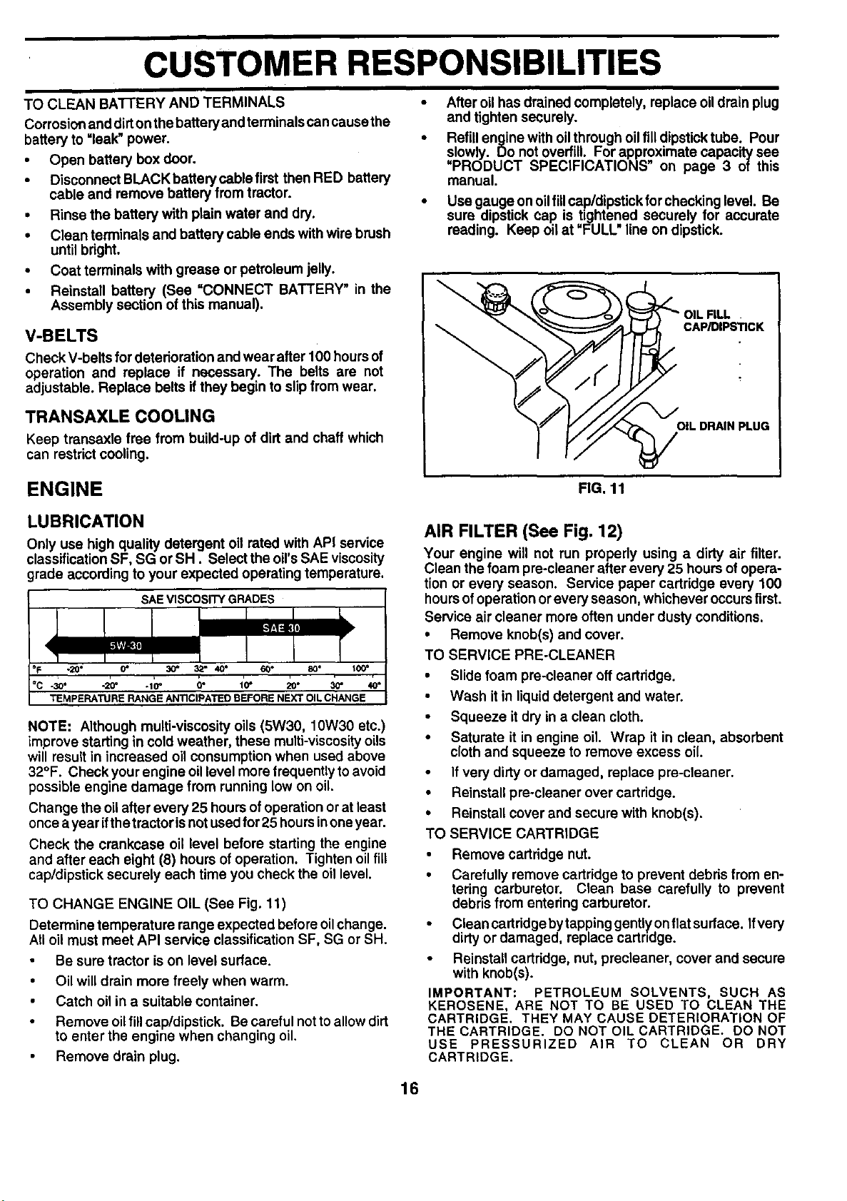
ENGINE
After oil has drained completely, replace oil drain plug
and tighten securely.
Refill engine with oil through oil fill dipsticktube. Pour
slowly. Do not overfill. For approximate capacity see
=PRODUCT SPECIFICATIONS" on page 3 of this
manual.
Use gauge on oilfillcap/dipstick forchecking level. Be
sure dipstick cap is tightened securely for accurate
reading. Keep oil at "FULL line on dipstick.
CAP/DIPS_CK
OIL DRAIN PLUG
FIG. 11
LUBRICATION
Only use high quality detergent oil rated with API service
classification SF, SG or SH. Select the oil's SAE viscosity
grade according to your expected operating temperature.
SAE VISCOSITY GRADES
-20° 0" 30" 3,_" 40° 60*
-so. -_" .1_" a" ;o- 20. _"
TEMPERATURE RANGE AN'nCIPATEO BEFORE NEXT OIL CHANGE
NOTE: Although multi-viscosity oils (5W30, 10W30 etc.)
improve starting in coldweather, these mulU-viscosity oils
will result in increased oil consumption when used above
32°F. Check your engine oil level more frequently to avoid
possible engine damage from running low on oil.
Change the oil after every 25 hours of operation or at least
once a year ifthe tractor isnot usedfor 25 hoursinoneyear.
Check the crankcase oil level before starting the engine
and after each eight (8) hours of operation. Tighten oilfill
cap/dipstick securely each time you check the oil level.
TO CHANGE ENGINE OIL (See Fig. 11)
Determine temperature range expected before oil change.
All oil must meet API service classification SF, SG or SH.
Be sure tractor is on level surface.
• Oil will drain more freely when warm.
Catch oil in a suitable container.
• Remove oil fill cap/dipstick. Be careful not to allow dirt
to enter the engine when changing oil.
Remove drain plug.
AIR FILTER (See Fig. 12)
Your engine will not run properly using a dirty air filter.
Clean the foam pre-cleaner after every 25 hours of opera-
tion or every season. Service paper cartridge every 100
hours of operation or every season, whichever occurs first.
Service air cleaner more often under dusty conditions.
• Remove knob(s) and cover.
TO SERVICE PRE-CLEANER
• Slide foam pre-cleener off cartridge.
• Wash itin liquiddetergent and water.
• Squeeze itdry in a clean cloth.
• Saturate it in engine oil. Wrap it in clean, absorbent
cloth and squeeze to remove excess oil.
If very dirty or damaged, replace pre-cleaner.
• Reinstall pre-cleaner over cartridge.
• Reinstall cover and secure with knob(s).
TO SERVICE CARTRIDGE
• Remove cartridge nut.
• Carefully remove cartridge to prevent debds from en-
tering carburetor. Clean base carefully to prevent
debris from entering carburetor.
• CleancartridgebytappinggenUyonflatsurface. Ifvery
dirtyor damaged, replace cartndge.
• Reinstall cartridge, nut, precleaner, cover and secure
with knob(s).
IMPORTANT: PETROLEUM SOLVENTS, SUCH AS
KEROSENE, ARE NOT TO BE USED TO CLEAN THE
CARTRIDGE. THEY MAY CAUSE DETERIORATION OF
THE CARTRIDGE. DO NOT OIL CARTRIDGE. DO NOT
USE PRESSURIZED AIR TO CLEAN OR DRY
CARTRIDGE.
16
 Loading...