

Craftsman 944.601892 Owner's Manual
8E/AR8
OWNER'S
MANUAL
MODEL NO.
944.601892
Caution:
Read and follow
all Safety Rules
and Instructions
Before Operating
This Eqmpment
ICRRFTSMRN°I
19.5 HP
ELECTRIC START
42" MOWER
AUTOMATIC
LAWN TRACTOR
• Assembly
• Operation
• Customer Responsibilities
• Service and Adjustments
• Repair Parts
Sears Canada, Inc., Toronto, Ontario M5B 2B8

SAFETY RULES
A
AI_ Safe Operation Practices for Ride-On Mowers
IMPORTANT: THIS CUTTtNG MACHINE IS CAPABLE OF AMPUTATING HANDS AND FEET AND THROWING OBJECTS.
FAILURE TO OBSERVE THE FOLLOWING SAFETY INSTRUCTIONS COULD RESULT IN SERIOUS INJURY OR DEATH.
I. GENERALOPERATION
• Read, understand, and follow all instructions in the
manual and on the machine before starting.
• Only allow responsibleadults, who are familiar with the
instructions, to operate the machine.
Clear the area ofobjects such as rocks, toys, wire, etc.,
which could be picked up and thrown by the blade.
Be sure thearea isclearofotherpeople before mowing.
Stop machine ifanyone enters the area.
• Never carry passengers.
• Do not mow in reverse unless absolutely necessary.
Always lookdown and behind before andwhile backing.
• Be aware ofthe mower discharge direction and do not
point it at anyone. Do not operate the mower without
either the entire grass catcher or the guard in place.
• Slow down before turning.
• Neverleavearunningmachineunattended. Alwaystum
off blades, set parking brake, stop engine, and remove
keys before dismounting.
• Turn offblades when not mowing.
• Stop engine before removing grass catcher or unclog-
ging chute.
• Mow only indaylight or good artificial light.
Do notoperate the machine while underthe influence of
alcoholor drugs.
• Watch fortrafficwhen operating near or crossingroad-
ways.
• Use extra care when loading or unloading the machine
into a trailer or truck.
• Data indicates thatoperators, age 60 years and above,
are involved in a large percentage of riding mower-
related injuries. These operators should evaluate their
ability to operate the riding mower safely enough to
protect themselves and others from serious injury.
• Keepmachine free of grass, leavesorotherdebrisbuild-
upwhichcan touchhotexhaust / engine partsand burn.
Do notallowthemower deck toplowleavesorotherdebris
which can cause build-upto occur. Clean any oil or fuel
spillage before operating or storing the machine. Allow
machine to coolbefore storage.
II. SLOPE OPERATION
Slopesare a majorfactor relatedto loss-of-controland tipover
accidents,whichcan result in severe injuryordeath. All slopes
requireextracaution.Ifyoucannotbackuptheslopeorifyoufeel
uneasyonit, do not mow it.
DO:
• Mow up and down slopes, notacross.
• Remove obstacles such as rocks, tree limbs, etc.
• Watch for holes, ruts, or bumps. Uneven terrain could
overturn the machine. Ta// grass can hide obstac/es.
• Use slow speed. Choose a low gear so that youwill not
have to stop or shift while on the slope.
• Followthe manufacturer's recommendations for wheel
weights or counterweights to improve stability.
• Use extra care with grass catchers or other attach-
ments. These can change the stability ofthe machine.
Keepall movement onthe slopess/owand gradual. Do not
make sudden changesin speed or direction.
Avoid starting or stopping on a slope. If tires lose traction,
disengage the blades and proceed slowly straight down the
slope.
2
DO NOT:
• Do not turnonslopes unless necessary, and then, turn
slowly and gradually downhill, if possible.
• Do not mow near drop-offs, ditches, or embankments.
The mowercould suddenly turnoverifa wheel isoverthe
edge of a cliffor ditch, or ifan edge caves in.
• Donotmowonwetgrass. Reducedtractioncouldcause
sliding.
• Donot try to stabilize the machine by putting yourfoot
on the ground.
• Do not use grass catcher on steep slopes.
III. CHILDREN
Tragic accidents can occur if the operator isnot alert to the
presence of children. Children are often attracted to the
machine and the mowing activity. Never assume that
children will remain where you last saw them.
• Keep children out of the mowing area and under the
watchful care of another responsible adult.
• Be alert and turn machine off if children enter the area.
• Before and when backing, look behind and down for
small children.
• Never carry children. They may fall off and beseriously
injured or interfere with safe machine operation.
° Never allow children to operate the machine.
• Use extra carewhen approaching blindcomers, shrubs,
trees, or other objects that may obscure vision.
IV. SERVICE
• Use extra care in handling gasoline and other fuels.
They are flammable and vapors are explosive.
- Use only an appreved container.
- Never remove gas cap or add fuel with the engine
running. AIIowenginetocool before refueling. Donot
smoke.
- Never refuelthe machine indoors.
- Neverstorethemachineorfuelcontainerinsidewhere
there is an open flame, such as a water heater.
• Never run a machine inside a closed area.
• Keep nutsand bolts,especially blade attachment bolts,
tightand keep equipment in good condition.
• Never tamper with safety devices. Check their proper
operation regularly.
• Keep machine free of grass, leaves, or other debris
build-up. Clean oilorfuel spillage. Allowmachinetocool
beforestoring.
Stop and inspect the equipment if you strike an object.
Repair, ifnecessary, before restarting.
• Never make adjustments or repairs with the engine
running.
• Grass catcher components are subject to wear, dam-
age, and deterioration,whichcouldexpose moving parts
orallowobjects to bethrown. Frequentlycheckcompo-
nents and replace with manufacturer's recommended
parts, when necessary.
Mower blades are sharp and can cut. Wrap the blade(s)
or wear gloves, and use extra caution when servicing
them.
• Check brake operation frequently. Adjust and service
as required.

SAFETY RULES
_Safe Operation Practices for Ride-On Mowers
Be sure the area is clear of other people before mowing. Slop
machine if anyone enters the area.
Never carry passengers or children even with the blades off.
Do not mow in reverse unless absolutely necessary. Always
look down and behind before and while backing.
Never carry children. They may fall off and be seriously
injured or interfere with safe machine operation.
Keep children out of the mowing area and under the watchful
care of another responsible adult.
Be alert and turn machine off if children enter the area.
Before and when backing, look behind and down for small
children.
Mow up and down slopes (15° Max), not across.
Remove obstacles such as rocks, tree limbs, etc.
Watch for holes, ruts, or bumps. Uneven terrain could over-
turn the machine. Tall grass can hide obstacles.
Use slow speed. Choose a low gear so that you will not have
to stop or shift while on the slope.
Avoid starting or stopping on a slope. If tires lose traction,
disengage the blades and proceed slowly straight down the
slope.
If machine stops while going uphill, disengage blades, shift
into reverse and back down slowly.
Do not turn on slopes unless necessary, and then, turn slowly
and gradually downhill, if possible.
Look for this symbol to point out important I
safety precautions. It means CAUTION!!!
I
BECOME ALERT!!! YOUR SAFETY IS IN-
VOLVED,
CAUTION: Do not coast down a hill in
neutral, you may Iosecontrol ofthetractor.
&
CAUTION: Tow only the attachments that
are recommended by and comply with
specifications of the manufacturer of your
tractor. Use common sense when towing.
Operate only at the lowest possible speed
when on a slope. Too heavy of a load, while
on a slope, is dangerous. Tires can lose
traction with the ground and cause you to
lose control of your tractor.
&
CAUTION: In order to prevent accidental
starting when setting up, transporting, ad-
justing or making repairs, always discon-
nect spark plug wire and place wire where
it cannot contact spark plug.
TABLE OF CONTENTS
SAFETY RULES ........................................................ 2-3
PRODUCT SPECIFICATIONS ....................................... 4
WARRANTY .................................................................. 4
CUSTOMER RESPONSIBILITIES ...................... 4, 15-18
ASSEMBLY ................................................................ 6-8
OPERATION ............................................................. 9-14
MAINTENANCE SCHEDULE ....................................... 15
SERVICE AND ADJUSTMENTS ............................. 19-23
STORAGE ................................................................... 24
TROUBLESHOOTING ............................................. 25-26
REPAIR PARTS -TRACTOR .................................. 28-45
REPAIR PARTS- ENGINE ...................................... 46-50
PARTS ORDERING/SERVICE ................. BACK COVER
3

RODUCT SPECIFICATIONS
GASOLINE CAPACITY 3.5 GALLONS
AND TYPE: UNLEADED REGULAR
OILTYPE(API-SF-SJ): SAE 30 (above 32°F)
SAE 5W-30 (below 32°F)
SYNTHETIC (below 0°F)
Your tractor was shipped from the factow with non-synthetic SAE
10W-30 motor oil.
OIL CAPACITY: 3 PINTS
SPARK PLUG: CHAMPION RJ19LM
GAP: .030")
GROUND SPEED (MPH): FORWARD: 5.5
REVERSE: 2.4
TIRE PRESSURE: FRONT: 14 PSI
REAR: 10 PSI
CHARGING SYSTEM: 3 AMPS BATTERY
5 AMPS HEADLIGHTS
BATIERY: AMP/HR: 30
MIN. CCA: 240
CASE SIZE: U1R
BLADE BOLT TORQUE: 27-35 FT. LBS.
MAINTENANCE AGREEMENT
A Maintenance Agreement is available on this product.
Contact your nearest Sears store for details.
CUSTOMER RESPONSIBILITIES
Read and observe the safety rules.
Follow a regularschedule in maintaining, caring for and
using your tractor.
• Follow the instructions under "Customer Responsibili-
ties" and "Storage" sections of this owner's manual.
WARNING: This tractor is equipped with an internal
combustion engine and should not be used on or near any
unimproved forest-covered, brush-covered or grass-cov-
ered land unless the engine's exhaust system is equipped
with a spark arrester meeting applicable local or state laws
(ifany). If a spark arrester is used, it should be maintained
in effective working order by the operator.
A spark arrester for the muffler is available through your
nearest authorized service center/Department (See RE-
PAIR PARTS section of this manual).
CONGRATULATIONS on your purchase ofa new tractor. It has been designed, engineered and manufactured to give you
the best possibledependability and performance.
Should you experience any problem you cannot easily remedy, please contact your nearest authorized service center/
department. We have competent, well-trained technicians and the proper tools to service or repair this tractor.
Please read and retain this man ual. The instructionswillenable you to assemble and maintain yourtractor properly. Always
observe the "SAFETY RULES".
WARRANTY
LIMITED TWO (2) YEAR WARRANTY ON CRAFTSMAN TRACTOR (RIDING EQUIPMENT)
For two (2) years from date of purchase Sears Canada, Inc. will repair or replace at Sears option free of charge parts which
are detective as a result of material or workmanship.
FULL ONE (1) YEAR WARRANTY ON BATrERY
For one (1) year from date of purchase, if any battery included with this riding equipment proves detective in material or
workmanship and our testing determines the battery will net hold a charge, Sears will replace the battery at no charge.
COMMERCIAL OR RENTAL USE
Warranty on Riding Equipment used for commercial or rental purposes is limited to ninety (90) days.
This Warranty does NOT cover:
1. Pre-delivery set-up.
2. Tire replacement or repair caused by punctures from outside objects (such as nails, thorns, stumps, or glass).
3. Expendable items which become worn during normal use, such as blades, spark plug, air cleaners and belts.
4. Repairs necessary because of operator abuse or negligence, including damaged jackshaft or mandrel and the
failure to operate and maintain the equipment according to the instructions contained in the Owner's Manual.
5. In Home service.
Warranty service is available by returning the Craftsman Riding Equipment to the nearest Sears Service Centre/Department in
Canada. This warranty applies only while this product is in use in Canada.
This warranty is in addition to any statutory warranty and does not exclude or limit legal rights you may have but shall run
concurrently with applicable provincial legislation. Furthermore, some provinces do NOT allow limitation on how long an
implied warranty will last so the above limitations may not apply to you.
SEARS CANADA, INC., TORONTO, ONTARIO M5B 2B8
4
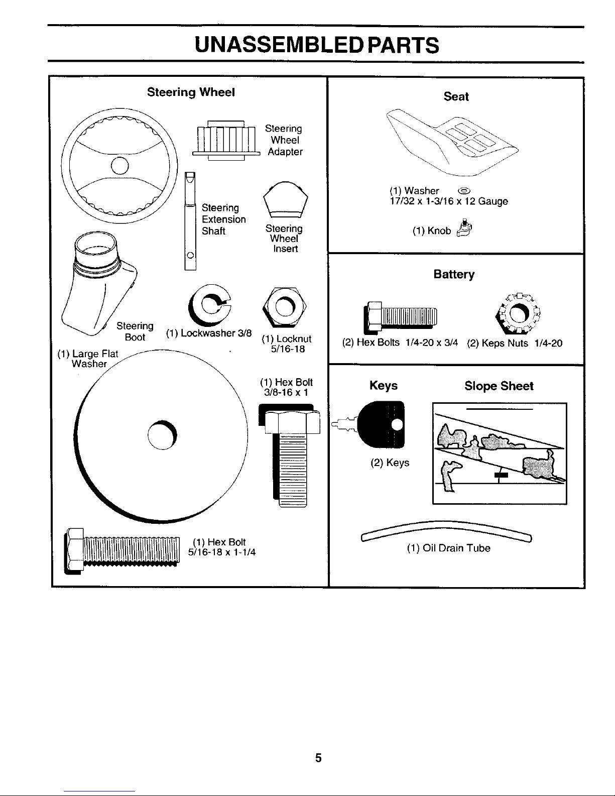
UNASSEMBLED PARTS
Steering Wheel
Steering
Boot
(1) Large Flat
Washer
Steering
Wheel
, , Adapter
I Steering
Extension
Shaft Steering
Wheel
Insert
(1) Lockwasher 3/8
(1) Locknut
5/16-18
(1) Hex Bolt
3/8-16 x 1
(1) Hex Bolt
5/16-18 x 1-1/4
Seat
\
\
\ J
(1) Washer
17/32 x 1-3/16 x 12 Gauge
(1) Knob
Battery
(2) Hex Bolts 1/4-20 x 3/4
(2) Keps Nuts 1/4-20
Keys Slope Sheet
(2) Keys
(1) Oil Drain Tube
5
ASSEMBLY
You rnew tractor has been assembled at the factory withexception ofthose parts left unassembled for shipping purposes. To
ensure safe and proper operation of your tractor all parts and hardware you assemble must be tightened securely. Use the
correct tools as necessary to insure proper tightness.
TOOLS REQUIRED FOR ASSEMBLY
A socket wrench set will make assembly easier. Standard
wrench sizes are listed.
(1) 9/16" wrench Pliers
(2) 7/16" wrenches Tirepressuregauge
(2) 1/2" wrenches Utility knife
When right or left hand is mentioned in this manual, it means
when you are in the operating position (seated behind the
steering wheel).
TO REMOVE TRACTOR FROM CARTON
UNPACK CARTON
• Remove all accessible loose parts and parts cartons
from carton.
• Cut, from top to bottom, along lines on all four corners
of carton, and lay panels flat.
• Check for any additional loose parts or cartons and
remove.
BEFORE REMOVING TRACTOR FROM
SKID
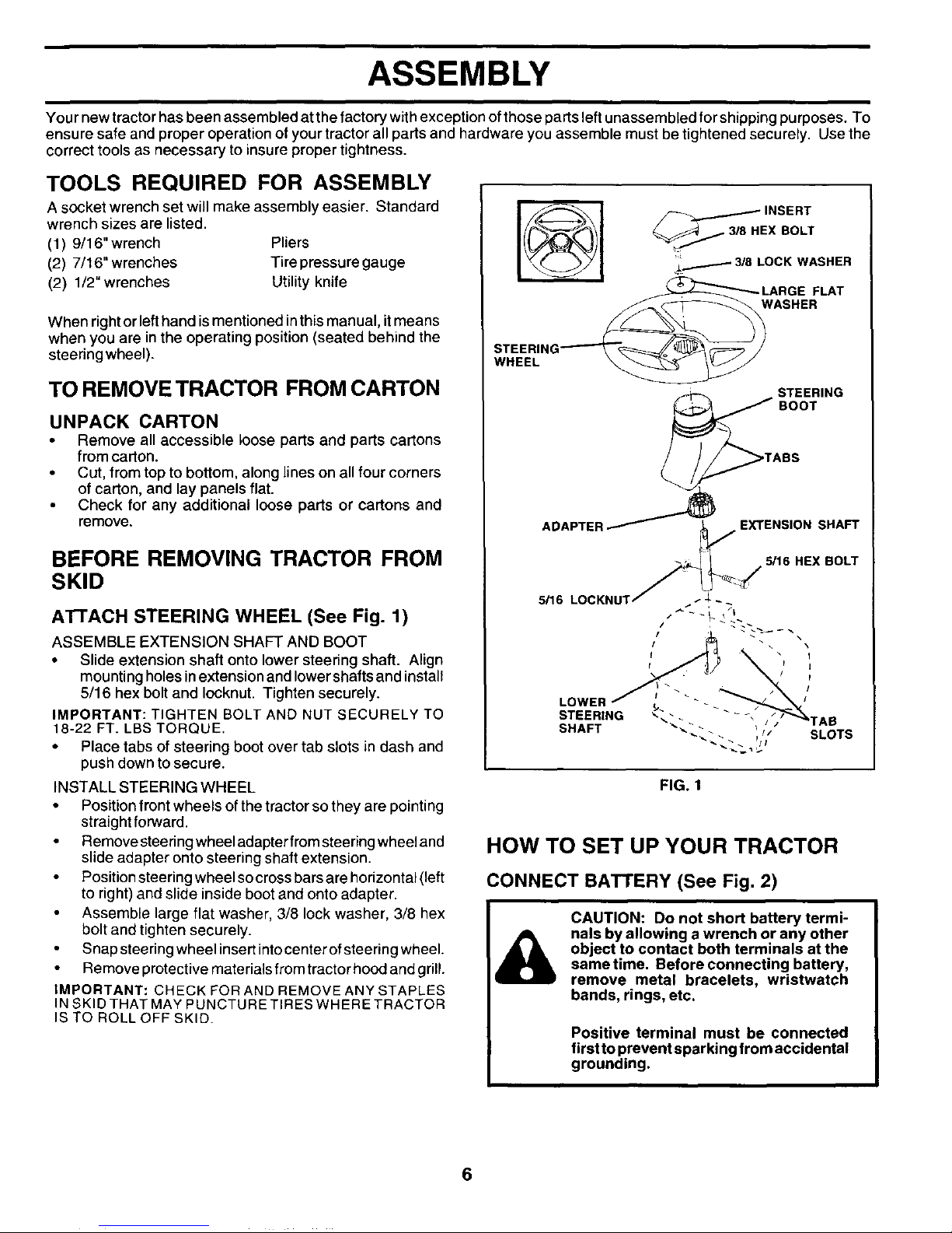
ATTACH STEERING WHEEL (See Fig. 1)
ASSEMBLE EXTENSION SHAFT AND BOOT
• Slide extension shaft onto lower steering shaft. Align
mounting holes in extension and Iowershafts and install
5/16 hex bolt and Iocknut. Tighten securely.
IMPORTANT: TIGHTEN BOLT AND NUT SECURELY TO
18-22 FT. LBS TORQUE.
• Place tabs of steering boot over tab slots in dash and
push down to secure.
INSTALL STEERING WHEEL
• Position front wheels of the tractor so they are pointing
straight forward.
• Remove steering wheel adapter from steering wheel and
slide adapter onto steering shaft extension.
Position steering wheel socross bars are horizontal (left
to right) and slide inside boot and onto adapter.
Assemble large flat washer, 3/8 lock washer, 3/8 hex
bolt and tighten securely.
Snap steering wheel insert into center of steering wheel.
Remove protective materials from tractor hood and grill.
IMPORTANT: CHECK FOR AND REMOVE ANY STAPLES
IN SKID THAT MAY PUNCTURE TIRES WHERE TRACTOR
IS TO ROLL OFF SKID.
_ INSERT
EX BOLT
_F 3/8 LOCK WASHER
FLAT
WASHER
STEERI_
WHEEL
ADAPTER
STEERING
BOOT
ASS
EXTENSION SHAFT
5/16 HEX BOLT
5/16 LOCKNUT
STEERING
SHAFT
FIG. 1
HOW TO SET UP YOUR TRACTOR
CONNECT BATTERY (See Fig. 2)
ASSEMBLY
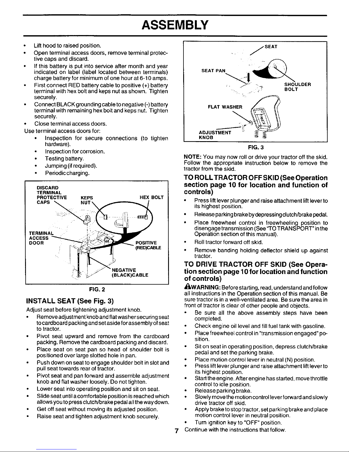
• Lift hood to raised position.
• Open terminal access doors, remove terminal protec-
tive caps and discard.
• If this battery is put into service after month and year
indicated on label (label located between terminals)
charge battery for minimum of one hour at 6-10 amps.
First connect RED battery cable to positive (+) battery
terminal with hex bolt and keps nut as shown. Tighten
securely.
• Connect BLACK grounding cable to negative (-) battery
terminal with remaining hex bolt and keps nut. Tighten
securely.
• Close terminal access doors.
Use terminal access doors for:
• Inspection for secure connections (to tighten
hardware).
Inspection for corrosion.
• Testing battery.
Jumping (if required).
Periodic charging.
DISCARD
TERMINAL
PROTECTIVE KEPS
CAPS
HEX BOLT
TERMINAL
ACCESS
DOOR POSITIVE
(RED)CABLE
NEGATIVE
(BLACK)CABLE
FIG. 2
INSTALL SEAT (See Fig. 3)
Adjust seat before tightening adjustment knob.
• Remove adjustment knob and flat washer securing seat
tocardboard packing and set aside for assembly of seat
to tractor.
• Pivot seat upward and remove from the cardboard
packing. Remove the cardboard packing and discard.
Place seat on seat pan so head of shoulder bolt is
positioned over large slotted hole in pan.
Push down on seat to engage shoulder bolt in slot and
pull seat towards rear of tractor.
• Pivot seat and pan forward and assemble adjustment
knob and flat washer loosely. Do not tighten.
Lower seat into operating position and sit on seat.
• Slide seat until a comfortable position isreached which
allows you to press clutch/brake pedal all the way down.
• Get off seat without moving its adjusted position.
Raise seat and tighten adjustment knob securely.
7
j SEAT
SEAT PAN _U
LDER
: ..... z BOLT
FLAT WASHE__ _
ADJUSTMENT _ _
KNOB _ _=_
FIG. 3
NOTE: You may now roll or drive your tractor off the skid.
Follow the appropriate instruction below to remove the
tractor from the skid.
TO ROLL TRACTOR OFF SKID (See Operation
section page 10 for location and function of
controls)
• Press lift lever plunger and raise attachment lift lever to
its highest position.
• Release parking brake by depressing clutch/brake pedal
• Ptace freewheel control in freewheeling position to
disengage transmission (See "TO TRANSPORT" inthe
Operation section of this manual).
• Roll tractor forward off skid.
• Remove banding holding deflector shieTd up against
tractor.
TO DRIVE TRACTOR OFF SKID (See Opera-
tion section page 10 for location and function
of controls)
_WARNING: Beforestarting, read, understand and follow
all instructions in the Operation section of this manual. Be
sure tractor isina well-ventilated area. Be sure thearea in
front of tractor isclear of other people and objects.
Be sure all the above assembly steps have been
completed.
• Check engine oillevel and fill fuel tank with gasoline.
• Place freewheel control in "transmission engaged" po-
sition.
• Sit on seat in operating position, depress clutch/brake
pedal and set the parking brake.
• Place motion control lever in neutral (N) position.
• Press lift lever plunger and raise attachment lift lever to
its highest position.
• Start the engine. After engine has started, move throttle
control to idle position.
• Release parking brake.
• Slowly move the motion control leverforward and slowly
drive tractor off skid.
Apply brake to stop tractor, set parking brake and place
motion control lever in neutral position.
• Turn ignition key to "OFF" position.
Continue with the instructionsthat follow.

ASSEMBLY
INSTALL MULCHER PLATE
(If previously removed) (See Fig.4)
Raise and hold deflector shield in upright position.
• Place front of mulcher plate over front of mower deck
opening and stide intoplace, as shown.
Hook front latch into hole on front of mower deck.
Hook rear latch into hole on back of mower deck.
|
CAUTION: Do not remove deflector |
shield from mower. Raise and hold shield
I
when attaching mulcher plate and allow
it to rest on plate while in operation.
DEFLECTOR
MULCHER
PLATE
LATCH
HOOKS
FIG. 4
TO CONVERT TO BAGGING OR
DISCHARGING
Simply remove mulcher plate and store in a safe place. Your
mower is now ready for discharging or installation of optional
grass catcher accessory.
NOTE: It is not necessary to change blades. The mulcher
blades are designed for discharging and bagging also.
CHECK TIRE PRESSURE
The tires on you r tractor were overinflated at the factory for
shipping purposes. Correct tire pressure is important for
best cutting performance.
Reduce tire pressure to PSI shown in "PRODUCT
SPECIFICATIONS" section of this manual.
CHECK DECK LEVELNESS
For best cutting results, mower housing should be properly
leveled. See'q'O LEVEL MOWER HOUSING" in the Service
and Adjustments section of this manual.
CHECK FOR PROPER POSITION OF ALL
BELTS
See the figures that are shown for replacing motion and
mower blade drive belts in the Service and Adjustments
section of this manual. Verify that the belts are routed
correctly.
CHECK BRAKE SYSTEM
After you learn how to operate your tractor, check to seethat
the brake is properly adjusted. See "TO ADJUST BRAKE"
in the Service and Adjustments section of this manual.
,/CHECKLIST
BEFORE YOU OPERA TEAND ENJOY YOUR NEW TRAC-
TOR, WE WISH TO ASSURE THAT YOU RECEIVE THE
BEST PERFORMANCEAND SA TISFACTION FROM THIS
QUALITYPRODUCT.
PLEASE REVIEW THE FOLLOWING CHECKLIST:
,/ All assembly instructions have been completed.
,/ No remaining loose parts in carton.
,/ Batteryis properlyprepared and charged. (Minimum 1
hour at 6 amps).
,/ Seat is adjusted comfortably and tightened securely.
,/ All tires are properly inflated. (For shipping purposes,
the tires were overinflated at the factory).
,/ Be sure mower deck is properly leveled side-to-side/
front-to-rear for best cutting results. (Tires must be
properly inflated for leveling).
,/ Check mower and drive belts. Be sure they are routed
properly around pulleys and inside all belt keepers.
,/ Check wiring. See that all connections are still secure
and wires are properly clamped.
,/ Before driving tractor, be sure freewheel control is in
drive position.
WHILE LEARNING HOW TO USE YOUR TRACTOR, PAY
EXTRA ATTENTION TO THE FOLLOWING IMPORTANT
ITEMS:
,/ Engine oil is at proper level.
,/ Fuel tank is filled with fresh, clean, regular unleaded
gasoline.
,/ Become familiar with all controls - their location and
function. Operate them before you star_ the engine.
,/ Be sure brake system is in safe operating condition.
/ It isimportantto purgethe transmissionbeforeoperating
yourtractor for thefirst time. Followproper starting and
transmission purging instructions (See "TO START
ENGINE"and"PURGE TRANSMISSION"in theOpera-
tion section of this manual).
8
OPERATION
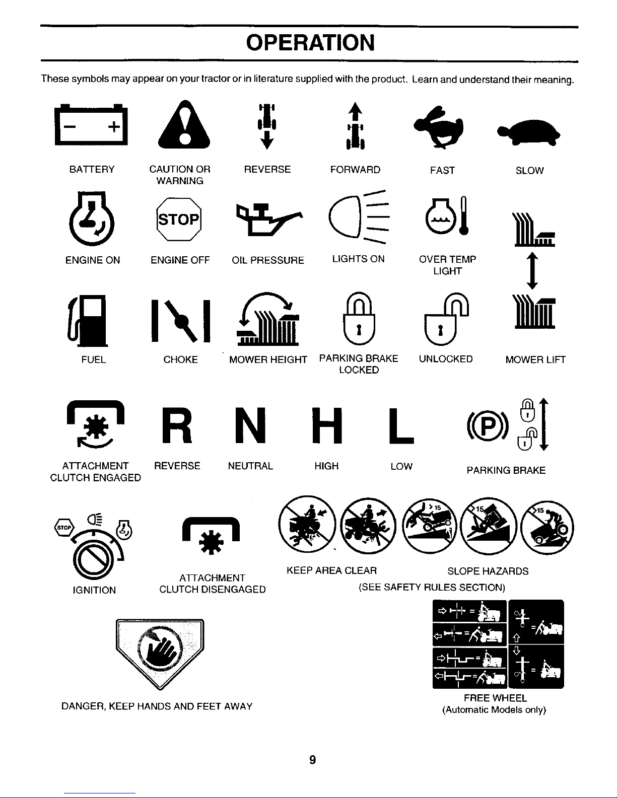
These symbols may appear on your tractoror in literature supplied with the product. Learn and understand their meaning.
BATTERY CAUTION OR REVERSE FORWARD FAST SLOW
WARNING
OIL PRESSURE LIGHTS ONENGINE ON ENGINE OFF
FUEL CHOKE " MOWER HEIGHT PARKING BRAKE UNLOCKED MOWER LIFT
LOCKED
R N
ATFACHMENT REVERSE
CLUTCH ENGAGED
H L
NEUTRAL HIGH LOW
PARKING BRAKE
KEEP AREA CLEAR SLOPE HAZARDS
ATTACHMENT
IGNITION CLUTCH DISENGAGED (SEE SAFETY RULES SECTION)
DANGER, KEEP HANDS AND FEET AWAY
9
FREE WHEEL
(Automatic Models only)
OPERATION
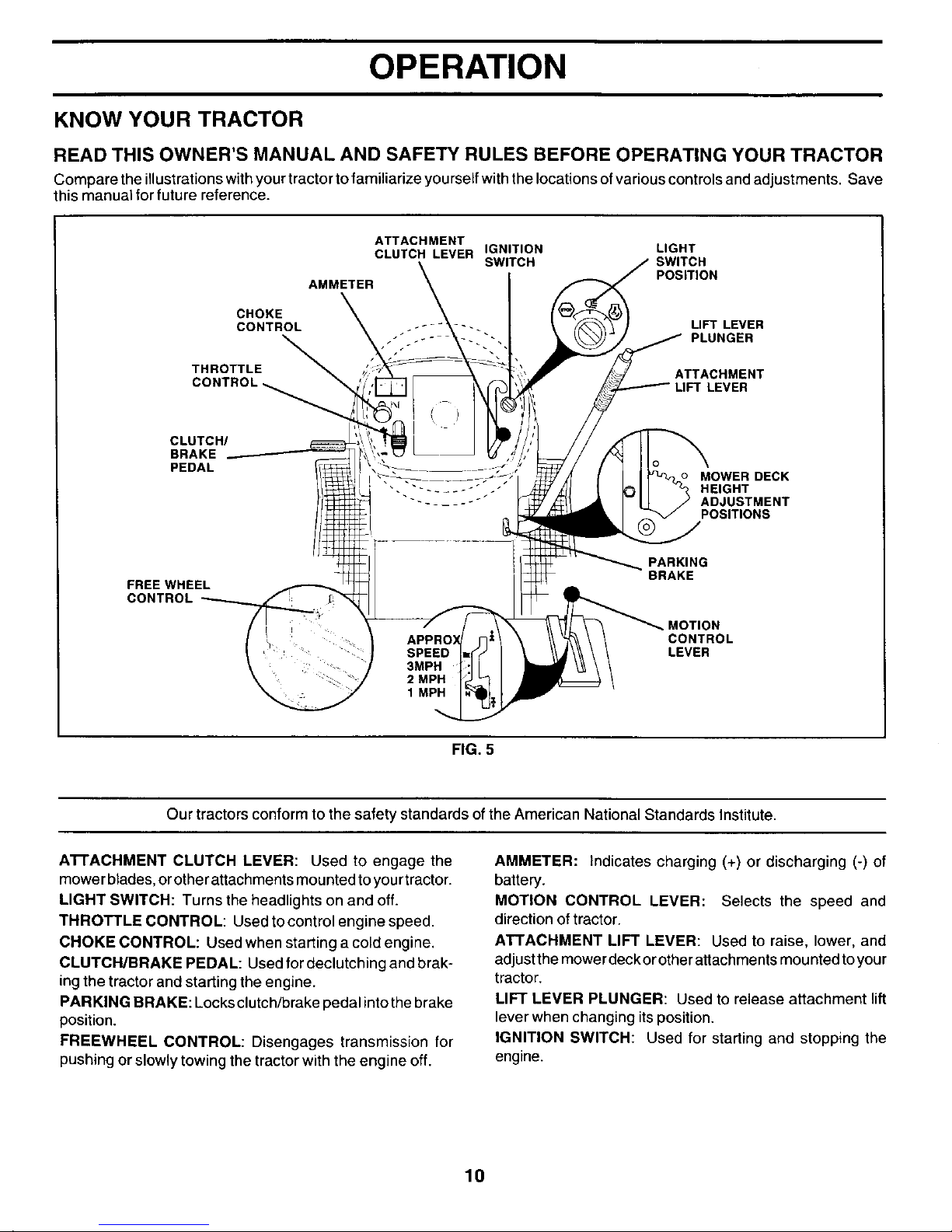
KNOW YOUR TRACTOR
READ THIS OWNER'S MANUAL AND SAFETY RULES BEFORE OPERATING YOUR TRACTOR
C_mpare the i__ustrati_nswithy_urtract_r t_ fami_iarize y_urse_fwiththe __cati_ns_fVari_us c_ntr__sandadjustments_ Save
this manual for future reference.
CHOKE
CONTROL
THROTTLE
ATTACHMENT
CLUTCH LEVER IGNITION LIGHT
SWITCH SWITCH
POSITION
AMMETER
LIFT LEVER
PLUNGER
ATTACHMENT
CLUTCH/
BRAKE
PEDAL
MOWER DECK
HEIGHT
ADJUSTMENT
POSITIONS
FREE WHEEL
CONTROL
PARKING
BRAKE
MOTION
CONTROL
LEVER
FIG. 5
Our tractors conform to the safety standards ofthe American National Standards Institute.
A'n'ACHMENT CLUTCH LEVER: Used to engage the
mower blades,orother attachmentsmounted to yourtractor.
LIGHT SWITCH: Turns the headlights on and off.
THROTTLE CONTROL: Used to control engine speed.
CHOKE CONTROL: Used when starting a cold engine.
CLUTCH/BRAKE PEDAL: Used for declutching and brak-
ingthe tractor and starting the engine.
PARKING BRAKE: Locksclutch/brake pedal intothe brake
position.
FREEWHEEL CONTROL: Disengages transmission for
pushing or slowly towing the tractorwiththe engine off.
AMMETER: Indicates charging (+) or discharging (-) of
battery.
MOTION CONTROL LEVER: Selects the speed and
direction oftractor.
ATTACHMENT LIFT LEVER: Used to raise, lower, and
adjust the mowerdeckor otherattachments mounted to your
tractor.
LIFT LEVER PLUNGER: Used to release attachment lift
lever when changing its position.
IGNITION SWITCH: Used for starting and stopping the
engine.
10
OPERATION
The operation of any tractor can result inforeign objects thrown into the eyes, which can
result in severe eye damage. Always wear safety glasses or eye shields while operating
your tractor or performing any adjustments or repairs. We recommend a wide vision
safety mask over spectacles orstandard safety glasses.
HOW TO USE YOUR TRACTOR
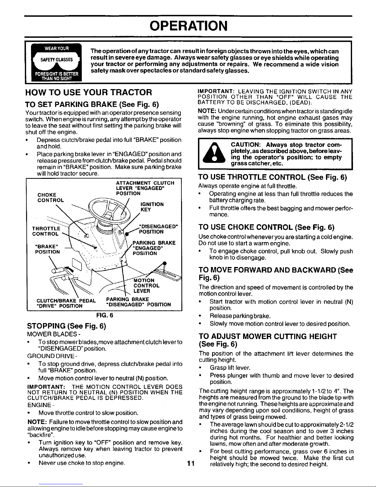
TO SET PARKING BRAKE (See Fig. 6)
You r tractor isequipped withan operator presence sensing
switch. When engine isrunning,anyattempt bythe operator
to leave the seat without first setting the parking brake will
shut off the engine.
• Depress clutch/brake pedal intofull "BRAKE" position
and hold.
Place parking brake lever in"ENGAGED" positionand
release pressure from clutch/brake pedal. Pedal should
remain in "BRAKE" position. Make sure parking brake
will hold tractorsecure.
ATTACHMENT CLUTCH
LEVER "ENGAGED"
POSITION
IGNITION
KEY
Y
j ,SENGAGED"
OSITION
PARKING BRAKE
/"ENGAGED"
POSITION
CONTROL
LEVER
CLUTCH/BRAKE PEDAL PARKING BRAKE
"DRIVE" POSITION "DISENGAGED" POSITION
FIG. 6
STOPPING (See Fig. 6)
MOWER BLADES -
To stop mower blades, move attachment clutch lever to
"DISENGAGED" position.
GROUND DRIVE-
• To stop ground drive, depress clutch/brake pedal into
full "BRAKE" position.
Move motion control lever to neutral (N) position.
IMPORTANT: THE MOTION CONTROL LEVER DOES
NOT RETURN TO NEUTRAL (N) POSITION WHEN THE
CLUTCH/BRAKE PEDAL IS DEPRESSED.
ENGINE -
• Move throttle control to slow position.
NOTE: Failure tomove throttlecontroltoslow positionand
allowing engine to idlebeforestopping may cause engine to
"backfire".
Turn ignition key to "OFF" position and remove key.
Always remove key when leaving tractor to prevent
unauthorized use.
Never use choke to stop engine.
IMPORTANT: LEAVING THE IGNITION SWITCH IN ANY
POSITION OTHER THAN "OFF" WILL CAUSE THE
BATTERY TO BE DISCHARGED, (DEAD).
NOTE: Undercertainconditionswhen tractorisstanding idle
with the engine running, hot engine exhaust gases may
cause "browning" of grass. To eliminate this possibility,
always stop engine when stopping tractor on grass areas.
I
|
CAUTION: Always stop tractor com- |
pletely, as described above, before leav-
I
ing the operator's position; to empty
grass catcher, etc.
TO USE THRO'n'LE CONTROL (See Fig. 6)
Always operate engine at full throttle.
• Operating engine at less than full throttle reduces the
batterycharging rate.
• Full throttleoffers the best bagging and mower perfor-
mance.
11
TO USE CHOKE CONTROL (See Fig. 6)
Use choke control whenever you are starting a coldengine.
Do not use to start a warm engine.
• To engage choke control, pull knob out. Slowly push
knob in to disengage.
TO MOVE FORWARD AND BACKWARD (See
Fig. 6)
The direction and speed of movement iscontrolled by the
motioncontrollever.
• Start tractor with motion control lever in neutral (N)
position.
Release parking brake.
• Slowly move motioncontrol lever to desired position.
TO ADJUST MOWER CUTTING HEIGHT
(See Fig. 6)
The position of the attachment lift lever determines the
cutting height.
Grasp lift lever.
Press plunger with thumb and move lever to desired
position.
The cutting height range is approximately 1-1/2 to 4". The
heights are measured from the ground to the blade tip with
the engine not running. These heights are approximate and
may vary depending upon soil conditions, height of grass
and types of grass being mowed.
• The average lawn should be cut to approximately 2-1/2
inches during the cool season and to over 3 inches
during hot months. For healthier and better looking
lawns, mow often and after moderate growth.
• For best cutting performance, grass over 6 inches in
height should be mowed twice. Make the first cut
relatively high; the second to desired height.
OPERATION
TO OPERATE ON HILLS
TO ADJUST GAUGE WHEELS (See Fig. 7)
Gauge wheels are properly adjusted when they are slightty
offthe ground when mower isat thedesired cutting height in
operating position. Gauge wheels then keep the deck in
proper position to help prevent scalping in most terrain
conditions•
NOTE:Adjust gauge wheels with tractor on a flat level
surface.
Adjust mower to desired cutting height (See "TO AD-
JUST MOWER CUTTING HEIGHT" in the Operation
section of this manual).
• With mower in desired height of cut position, gauge
wheels should be assembled so they are slightly off the
ground. Install gauge wheel in appropriate hole with
shoulder bolt, 3/8 washer, and 3/8-16 Iocknut and tighten
securely.
• Repeat for opposite side installing gauge wheel in same
adjustment hole.
GUAGE WHEEL
MOUNTING
BRACI(ET
318 WASHEI
GAUGE WHEEL
SHOULDER
BOLT
FIG. 7
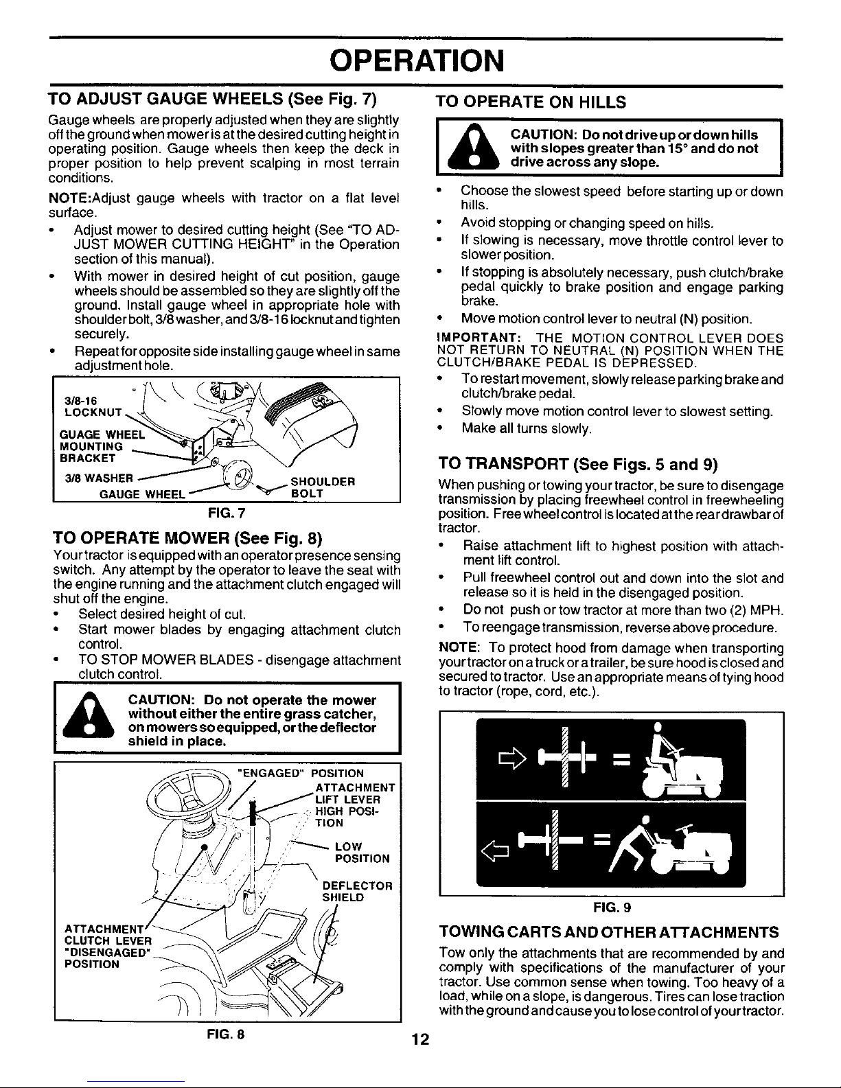
TO OPERATE MOWER (See Fig. 8)
Your tractor isequipped with an operator presence sensing
switch. Any attempt by the operator to leave the seat with
the engine running and the attachment clutch engaged will
shut off the engine.
• Select desired height of cut.
• Start mower blades by engaging attachment clutch
control.
TO STOP MOWER BLADES - disengage attachment
clutch control.
CAUTION: Do not operate the mower
without either the entire grass catcher,
on mowers soequipped, or the deflector
shield in place.
"ENGAGED" POSITION
ATTACHMENT
DEFLECTOR
SHIELD
ATTACH_
CLUTCH LEVER
"DISENGAGED"
POSITION
I_lb AUTION: Donotdriveupordownhills I
with slopes greater than 15° and do not
drive across any slope.
• Choose the slowest speed before starting up or down
hills.
Avoid stopping or changing speed on hills.
If slowing is necessary, move throttle control lever to
slower position.
If stopping is absolutely necessary, push clutch/brake
pedal quickly to brake position and engage parking
brake.
• Move motion control lever to neutral (N) position.
IMPORTANT: THE MOTION CONTROL LEVER DOES
NOT RETURN TO NEUTRAL (N) POSITION WHEN THE
CLUTCH/BRAKE PEDAL IS DEPRESSED.
• To restart movement, slowly release parking brakeand
clutch/brake pedal.
• Slowly move motion control lever to slowest setting.
• Make all turns slowly•
TO TRANSPORT (See Figs. 5 and 9)
When pushing or towing yourtractor, be sure to disengage
transmission by placing freewheel control in freewheeling
position. Free wheel control islocated atthe reardrawbar of
tractor.
• Raise attachment lift to highest position with attach-
ment lift control.
• Pull freewheel control out and down into the slot and
release so it is held in the disengaged position.
• Do not push or tow tractor at more than two (2) MPH.
• To reengage transmission, reverse above procedure.
NOTE: To protect hood from damage when transporting
yourtractor ona truck or atrailer, be surehood isclosed and
securedtotractor. Useanappropriatemeansoftying hood
to tractor (rope, cord, etc.).
FIG. 9
TOWING CARTS AND OTHER A'n'ACH MENTS
Tow only the attachments that are recommended by and
comply with specifications of the manufacturer of your
tractor. Use common sense when towing. Too heavy of a
load, while on a slope, is dangerous. Tires can lose traction
with the ground and cause you to lose control ofyour tractor.
FIG. 8 12
OPERATION
BEFORE STARTING THE ENGINE
CHECK ENGINE OIL LEVEL
• The engine in your tractor has been shipped, from the
factory, already filled with summer weight oil.
• Check engine oil with tractor on level ground.
Remove oil fill cap/dipstick and wipe clean, reinsert the
dipstick and screw cap tight, wait for a few seconds,
remove and reacl oil level. I! necessary, add oil until
"FULL" mark on dipstick is reached. Do not overfill.
• For cold weather operation you should change oil for
easier starting (See =OIL VISCOSITY CHART" in the
Customer Responsibilities section of this manual).
To change engine oil,see the Customer Responsibilities
section in this manual.
ADD GASOLINE
• Fill fuel tank. Use fresh, clean, regular unleaded
gasoline with a minimum of 87 octane. (Use of leaded
gasoline will increase carbon and lead oxide deposits
and reduce valve life). Do not mix oil with gasoline.
Purchase fuel in quantities that can be used within 30
days to assure fuel freshness.
IMPORTANT: WHEN OPERATING IN TEMPERATURES
BELOW 32°F(0°C), USE FRESH, CLEAN WINTER GRADE
GASOLINE TO HELP INSURE GOOD COLD WEATHER
STARTING.
WARNING: Experience indicates that alcohol blended fuels
(called gasohol or using ethanol or methanol) can attract
moisture which leads to separation and formation of acids
during storage. Acidic gas can damage the fuel system of
an engine while in storage. To avoid engine problems, the
fuel system should be emptied before storage of 30 days or
longer. Drain the gas tank, start the engine and let it run until
the fuel lines and carburetor are empty. Use fresh fuel next
season. See Storage Instructions for additional information.
Never use engine orcarburetor cleaner products in the fuel
tank or permanent damage may occur.
CAUTION: Fill to bottom of gas tank I
filler neck. Do not overfill Wipe off any
I
spilled oil or fuel. Do not store, spill or
use gasoline near an open flame,
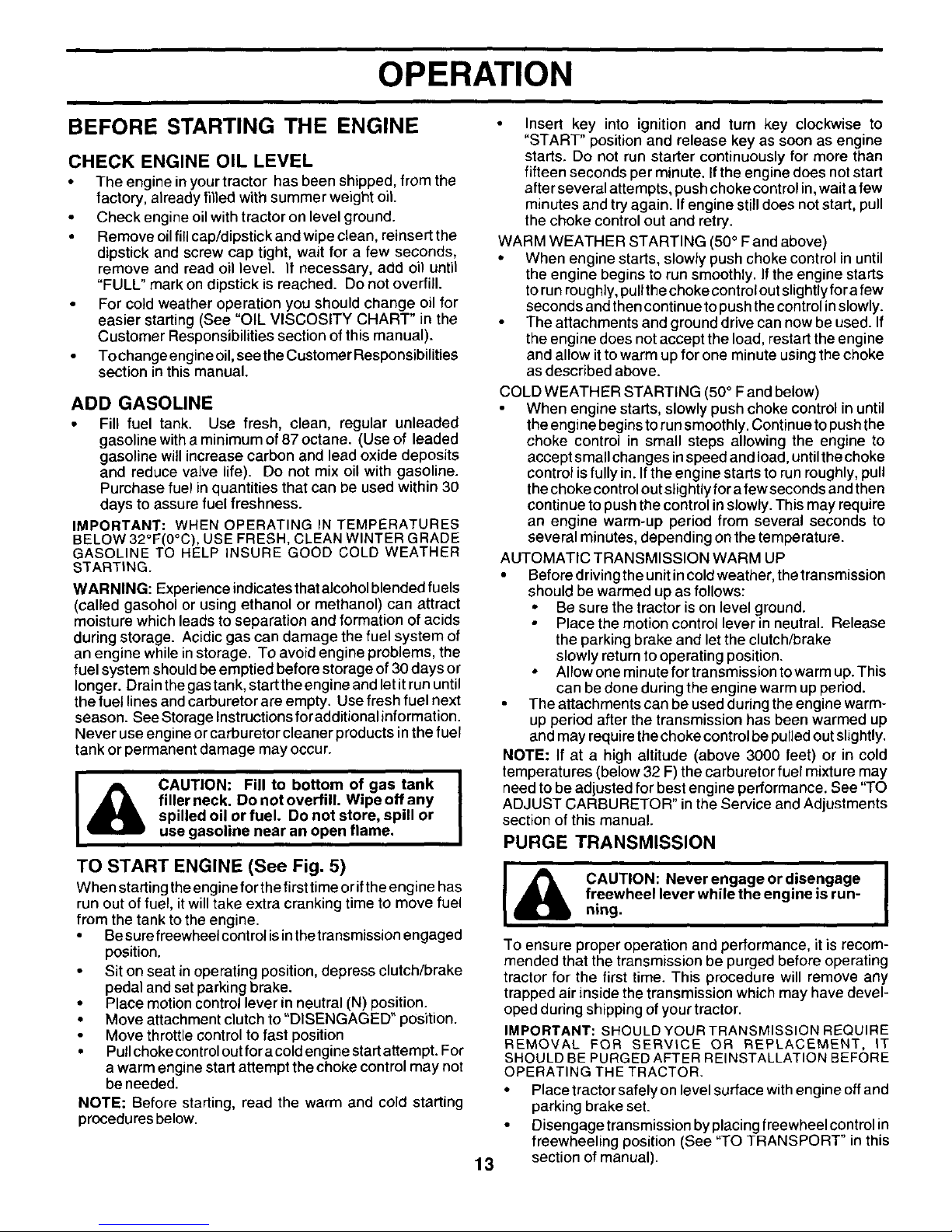
TO START ENGINE (See Fig. 5)
When starting the engine for the first time or ifthe engine has
run out of fuel, it will take extra cranking time to move fuel
from the tank to the engine.
• Besure freewheelcont rol isinthe transmission engaged
position.
• Sit on seat in operating position, depress clutch/brake
pedal and set parking brake.
• Place motion control lever in neutral (N) position.
• Move attachment clutch to"DISENGAGED" position.
Move throttle control to fast position
• Pullchoke control out for a cold engine start attempt. For
a warm engine start attempt the choke control may not
be needed.
NOTE: Before starting, read the warm and cold starting
procedures below.
• Insert key into ignition and turn key clockwise to
"START" position and release key as soon as engine
starts. Do not run starter continuously for more than
fifteen seconds per minute. Ifthe engine does not start
afterseveral attempts, push choke controlin,waitafew
minutes and tryagain. If engine stilldoes notstart, pull
the choke control out and retry.
WARM WEATHER STARTING (50° F and above)
• When engine starts, slowly push choke control in until
the engine begins to run smoothly. If the engine starts
torun roughly,pullthechoke controloutslightly fora few
seconds andthen continuetopush thecontrolinslowly.
The attachments and ground drive can now be used. If
the engine does not accept the load, restart the engine
and allow ittowarm up for one minute usingthe choke
as described above.
13
COLD WEATHER STARTING (50 ° F and below)
When engine starts, slowly push choke control in until
the engine begins to run smoothly. Continue to push the
choke control in small steps allowing the engine to
accept small changes inspeed and load, until the choke
control is fully in. If the engine starts to run roughly, pull
the choke control out slightly for a few seconds and then
continue to push the control in slowly. This may require
an engine warm-up period from several seconds to
several minutes, depending on the temperature.
AUTOMATIC TRANSMISSION WARM UP
• Before driving the unit in cold weather, the transmission
should be warmed up as follows:
• Be sure the tractor is on level ground.
Place the motion control lever in neutral. Release
the parking brake and let the clutch/brake
slowly return to operating position.
• Allow one minute for transmission to warm up. This
can be done during the engine warm up period.
The attachments can be used during the engine warm-
up period after the transmission has been warmed up
and may require the choke control be pulled out slightly.
NOTE: If at a high altitude (above 3000 feet) or in cold
temperatures (below 32 F) the carburetor fuel mixture may
need to be adjusted for best engine performance. See "TO
ADJUST CARBURETOR" in the Service and Adjustments
section of this manual.
PURGE TRANSMISSION
CAUTION: Never engage or disengage I
freewheel lever while the engine is run-
ning.
To ensure proper operation and performance, it is recom-
mended that the transmission be purged before operating
tractor for the first time. This procedure will remove any
trapped air inside the transmission which may have devel-
oped during shipping of your tractor.
IMPORTANT: SHOULD YOUR TRANSMISSION REQUIRE
REMOVAL FOR SERVICE OR REPLACEMENT, IT
SHOULD BE PURGED AFTER REINSTALLATION BEFORE
OPERATING THE TRACTOR.
• Place tractor safely on level surface with engine off and
parking brake set.
• Disengage transmission by placing freewheel control in
freewheeling position (See "TO TRANSPORT" in this
section of manual).

OPERATION
• Sitting in the tractor seat, start engine. After the engine
is running, move throttle control to slow position. With
motion control lever in neutral (N) position, slowly
disengage clutch/brake pedal.
• Move motion control lever to full forward position and
hold for five (5) seconds. Move lever to full reverse
position and hold for five (5) seconds. Repeat this
procedure three (3) times.
NOTE: During this procedu re there will be no movement of
drive wheels. The air is being removed from hydraulic drive
system.
• Move motion control lever to neutral (N) position. Shut-
off engine and set parking brake.
Engage transmission by placing freewheel control in
driving position (See "TO TRANSPORT" in this section
of manual).
• Sitting inthe tractor seat, start engine. After the engine
is running, move throttle control to half (1/2) speed. With
motion control lever in neutral (N) position, slowly
disengage clutch/brake pedal.
• Slowly move motion control lever forward, after the
tractor moves approximately five (5) feet, slowly move
motion control lever to reverse position. Afterthe tractor
moves approximately five (5) feet return the motion
control lever to the neutral (N) position. Repeat this
procedu re with the motion control lever three (3) times.
• Your tractor is now purged and now ready for normal
operation.
MOWING TIPS
Mower should be properly leveled for best mowing
performance. See "TO LEVEL MOWER HOUSING" in
the Service and Adjustments section of this manual.
The left hand side of mower should be used fortrimming.
Drive sothat clippings are discharged onto the area that
has been cut. Have the cut area to the right of the
machine. This will result in a more even distribution of
clippings and more uniform cutting.
• When mowing large areas, starf byturning tothe right so
that clippings will discharge away from shrubs, fences,
driveways, etc. After one or two rounds, mow in the
opposite direction making left hand turns until finished
(See Fig. 10).
If grass is extremely tall, it should be mowed twice to
reduce load and possible fire hazard from dried clip-
pings. Make first cut relatively high; the second to the
desired height.
Do not mow grass when it is wet. Wet grass will plug
mower and leave undesirableclumps. Allow grasstodry
before mowing.
Always operate engine at full throttle when mowing
to assure better mowing performance and proper dis-
charge of material. Regulate ground speed by selecting
a low enough gear to give the mower cutting perfor-
mance as well as the quality of cut desired.
• When operating attachments, select a ground speed
that wilt suit the terrain and give best performance of the
attachment being used.
f
1
e,l
iL¢
J
FIG. 10
J
MULCHING MOWING TIPS
IMPORTANT: FOR BEST PERFORMANCE, KEEP MOWER
HOUSING FREE OF BUILT-UP GRASS AND TRASH.
CLEAN AFTER EACH USE.
• Thespecial mulching bladewill recutthegrassclippings
many times and reduce them in size so that as they fall
onto the lawn they will disperse into the grass and not be
noticed. Also, the mulched grass will biodegrade
quickly to provide nutrients for the lawn. Always mulch
with your highest engine (blade) speed as this will
provide the best recutting action of the blades.
Avoid cutting you r lawn when it iswet. Wet grass tends
to form clumps and interferes with the mulching action.
The best time to mow your lawn is the early afternoon.
At this time the grass has dried and the newly cut area
will not be exposed to the direct sun.
• For best results, adjust the mower cutting height sothat
the mower cuts off only the top one-third of the grass
blades (See Fig. 11). For extremely heavy mulching,
reduce yourwidth of cut on each pass and mow slowly.
• Certain types of grass and grassconditions may require
that an area be mulched a second time to completely
hide the clippings. When doing a second cut, mow
across or perpendicular to the first cut path.
Change your cutting pattern from week to week. Mow
north tosouth one week then change to east to west the
next week. This will help prevent matting and graining
of the lawn.
FIG. 11
14
t
CUSTOMER RESPONSIBILITIES
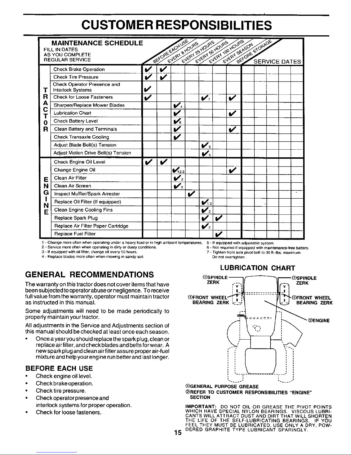
MAINTENANCE SCHEDULE _,_ _,_/_/_ ./_'_/_/'*
P,LL,NOATES
....
-_"/£-q_"/£-4_'J£-_r_ S E R V I C E DATES
Check Brake Operation _V'
Check Tire Pressure
Check Operator Presence and
TR Interlock Systems _#,
Check for Loose Fasteners 1_7
Sharpen/Replace Mower Blades _4
Lubrication Chart V'
m Check Battery Level
R Clean Battery and Terminals if
Check Transaxle Cooling V'
Adjust Blade Belt(s) Tension _5
Adjust Motion Drive Belt(s) Tension _5
Check Engine Oil Level V' V'
Change Engine Oil _2,_ I_
E Clean Air Filter 1_2
N Clean Air Screen 11_2
G Inspect Muffler/Spark Arrester
Replace Oil Filter (If equipped) 1_12
E Clean Engine Cooling Fins m_S2
Replace Spark Plug V' V'
Replace Air Filter Paper Cartridge V'2
Replace Fuel Filter if
1 - Change more often when operating under a heavy load or in high ambient temperatures. 5 - If equipped with adjustable system.
2 - Service more often when operating in dirty or dusty conditions. 6 - Not required if equipped with maintenance-tree battery.
3 - If equipped with oil filter, change oil every 50 hours. 7 - Tighten front axle pivot bolt to 35 ft.-Ibs, maximum.
4 - Replace blades more often when mowing in sandy soil Do not overtighten.
GENERAL RECOMMENDATIONS
LUBRICATION CHART
The warranty on this tractor does not cover items that have ZERK ,*"_t"_
been subjected tooperatorabuse ornegligence. To receive
full value from the warranty, operator must maintain tractor _)FRONTWIlE
as instructed in this manual. BEARINGZERK
Some adjustments will need to be made periodically to
properly maintain your tractor.
All adjustments in the Service and Adjustments section of
this manual should be checked at least once each season.
• Once a year you should replace the spark plug, clean or
replace air filter, and check blades and belts for wear. A
new spark plug andclean air filter assure proper air-fuel
mixture and help yourengine run betterand last longer.
BEFORE EACH USE
• Check engine oil level.
• Check brake operation.
• Check tire pressure.
• Check operator presence and
interlock systems for proper operation.
Check for loose fasteners.
ZERK
_(_FRONT WHEEL
BEARING ZERK
15
i i
i i
_GENERAL PURPOSE GREASE
_REFER TO CUSTOMER RESPONSIBILITIES "ENGINE"
SECTION
IMPORTANT: DO NOT OIL OR GREASE THE PIVOT POINTS
WHICH HAVE SPECIAL NYLON BEARINGS. VISCOUS LUBRI-
CANTS WILL ATTRACT DUST AND DIRT THAT WILL SHORTEN
THE LIFE OF THE SELF*LUBRICATING BEARINGS. IF YOU
FEEL THEY MUST BE LUBRICATED, USE ONLY A DRY, POW-
DERED GRAPHITE TYPE LUBRICANT SPARINGLY.
CUSTOMER RESPONSIBILITIES
TRAILING
EDG EUP
TRACTOR
Always observe safety ruleswhen performing any mainte-
nance.
BRAKE OPERATION
If tractor requires more than six (6) feet stopping distance at
high speed in highest gear, then brake must be adjusted.
(See "TO ADJUST BRAKE" inthe Service and Adjustments
section of this manual).
TIRES
• Maintain proper air pressure inalltires (See"PRODUCT
SPECIFICATIONS" section of this manual).
Keep tires free of gasoline, oil, or insect control chemi-
cals which can harm rubber.
• Avoid stumps, stones, deep ruts, sharp objects and
other hazards that may cause tire damage.
NOTE: To seal tire punctures and prevent flat tires due to
slow leaks, tire sealant may be purchased from your local
parts dealer. Tire sealant also prevents tire dry rot and
corrosion.
OPERATOR PRESENCE SYSTEM
Be sure operator presence and interlock systems are work-
ing properly. If your tractor does not function as described,
repair the problem immediately.
• The engine should not start unless the clutch/brake
pedal is fully depressed and attachement clutch control
is in the disengaged position.
• When the engine is running, any attempt bythe operator
to leave the seat without first setting the parking brake
should shut off the engine.
• When the engine isrunning and the attachment clutch is
engaged, any attempt by the operator to leave the seat
should shut off the engine.
• The attachment clutch should never operate unless the
operator is in the seat.
BLADE CARE
For best results mower blades must be kept sharp. Replace
bent or damaged blades.
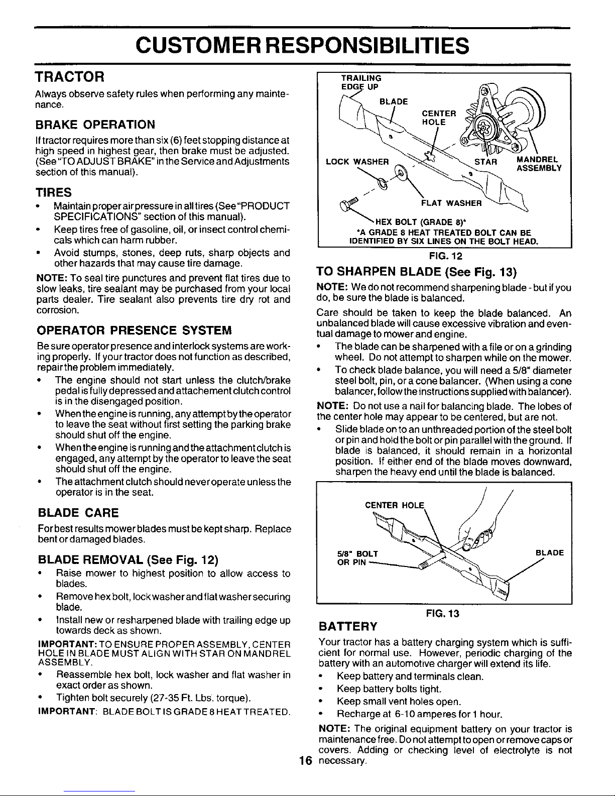
BLADE REMOVAL (See Fig. 12)
• Raise mower to highest position to allow access to
blades.
• Remove hex bolt, lock washer and flat washer securing
blade.
• Install new or resharpened blade with trailing edge up
towards deck as shown.
IMPORTANT: TO ENSURE PROPER ASSEMBLY, CENTER
HOLE iN BLADE MUST ALIGN WITH STAR ON MANDREL
ASSEMBLY.
• Reassemble hex bolt, lock washer and flat washer in
exact order as shown.
• Tighten bolt securely (27-35 Ft. Lbs. torque).
IMPORTANT: BLADE BOLT IS GRADE 8 HEAT TREATED.
BLADE
LOCK WASHER
CENTER
HOLE _
STAR MANDREL
ASSEMBLY
J
FLAT WASHER
HEXBOLT(GRADE8)*
*A GRADE8HEATTREATEDBOLTCANBE
IDENTIFIEDBY SIXLINESONTHEBOLTHEAD.
FIG. 12
TO SHARPEN BLADE (See Fig. 13)
NOTE: We do notrecommend sharpening blade - but ifyou
do, be sure the blade is balanced.
Care should be taken to keep the blade balanced. An
unbalanced blade will cause excessive vibration and even-
tual damage to mower and engine.
• The blade can be sharpened with a file or on a grinding
wheel. Do not attempt to sharpen while on the mower.
• To check blade balance, you will need a 5/8" diameter
steel bolt, pin, or a cone balancer. (When using a cone
balancer, follow the instructions supplied with balancer).
NOTE: Do not use a nail for balancing blade. The lobes of
the center hole may appear to be centered, but are not.
• Slide blade on to an unth readed portion of the steel bolt
or pin and hold the bolt or pin parallel with the ground. If
blade is balanced, it should remain in a horizontal
position. If either end of the blade moves downward,
sharpen the heavy end until the blade is balanced.
CENTER HOLE / /
5/8" BOLT BLADE
OR PIN
FIG. 13
BATTERY
Your tractor has a battery charging system which is suffi-
cient for normal use. However, periodic charging of the
battery with an automotive charger will extend its life.
Keep battery and terminals clean.
Keep battery bolts tight.
• Keep small vent holes open.
Recharge at 6-10 amperes for I hour.
NOTE: The original equipment battery on your tractor is
maintenance free. Do not attempt to open or remove caps or
covers. Adding or checking level of electrolyte is not
16 necessary.
 Loading...