

Craftsman 944.600191 Owner's Manual

SEARS
OWNER'S
MANUAL
MODEL NO.
944.600191
Caution:
Read and follow
all Safety Rules
and Instructmns
Before Operating
This Equipment
CRAFTSMAN+
19.5 HP
ELECTRIC START
42" MOWER
6 SPEED TRANSAXLE
LAWN TRACTOR
• Assembly
• Operation
• Customer Responsibilities
• Service and Adjustments
• Repair Parts
__.____.____----
Sears Canada, Inc., Toronto, Ontario M5B 2B8
SAFETY RULES,
A
_:_ Safe Operation Practices for Ride-On Mowers
IMPORTANT: THIS CUTTING MACHINE IS CAPABLE OF AMPUTATING HANDS AND FEET AND THROWING OBJECTS.
FAILURE TO OBSERVE THE FOLLOWING SAFETY INSTRUCTIONS COULD RESULT IN SERIOUS INJURY OR DEATH,
I. GENERAL OPERATION
• Read, understand, and follow all instructions in the
manual and on the machine before starting.
• Only allow responsible adults, whoare familiar with the
instructions, to operate the machine.
• Cleartheareaofobjectssuchas rocks,toys, wire, etc.,
which could be picked up and thrownby the blade.
• Be sure the area isclear of otherpeople beforemowing.
Stop machine if anyone enters the area.
• Never carry passengers.
• Do not mow in reverse unless absolutely necessary.
Always look down andbehind beforeandwhilebacking.
• Be aware of the mower discharge direction and do not
point it at anyone. Do not operate the mower without
either the entire grass catcher orthe guard inplace.
• Slowdown before turning.
• Neverleavearunningmachineunattended. Alwaysturn
offblades, set parking brake, stop engine, and remove
keys before dismounting.
• Turn offblades when notmowing.
• Stop engine before removing grass catcher or unclog-
ging chute.
• Mow only in daylight or good artificial light.
• Donotoperatethemachinewhileundertheinfluenceof
alcohol ordrugs.
• Watch for traffic when operatingnear orcrossing read-
ways.
• Use extra care when loading or unloading the machine
into a trailer or truck.
• Data indicates thatoperators, age 60 years and above,
are involved in a large percentage of riding mower-
related injuries. These operators should evaluate their
ability to operate the riding mower safely enough to
protect themselves and others from serious injury.
II. SLOPE OPERATION
Slopes are a major factor related to loss-of-control and
tipoveraccidents, which can result insevere injuryor death.
Allslopes require extra caution. If you cannot back up the
slope or ifyou feel uneasy on it,do not mow it.
DO:
• Mow up and down slopes, not across.
• Remove obstacles such as rocks, tree limbs, etc.
• Watch for holes, ruts, or bumps. Uneven terrain could
overturn the machine. Ta//grass can hide obstac/es.
• Useslowspeed. Choose a lowgear sothat you willnot
have to stop or shift while on the slope.
• Followthe manufacturer's recommendations for wheel
weights or counterweights to improve stability.
Use extra care with grass catchers or other attach-
ments. These can change the stability ofthe machine.
• Keep all movement onthe slopes s/owand gradual. Do
not make sudden changes in speed or direction.
Avoid starting or stopping on a slope. If tires lose
traction, disengage the blades and proceed slowly
straightdown the slope.
DO NOT:
• Do not turn on slopes unless necessary, and then, turn
slowly and gradually downhill, if possible.
• Do notmow near drop-offs, ditches, or embankments.
The mower could suddenly turn over ifawheel isover the
edge of a cliff or ditch, or if an edge caves in.
• Do notmow on wetgrass. Reduced traction could cause
sliding.
• Do not try to stabilize the machine by putting your foot
on the ground.
• Do not use grass catcher on steep slopes.
III. CHILDREN
Tragic accidents can occur if the operator is notalert to the
presence of children. Children are often attracted to the
machine and the mowing activity. Never assume that
children will remain where you last saw them.
• Keep children out of the mowing area and under the
watchful care of another responsible adult.
• Be alert and turn machine off ifchildren enter the area.
• Before and when backing, look behind and down for
small children.
• Never carry children. They may fall off and be seriously
injured or interfere with safe machine operation.
• Never allow children to operate the machine.
• Useextra care when approaching blind comers, shrubs,
trees, or other objects that may obscure vision.
IV. SERVICE
• Use extra care in handling gasoline and other fuels.
They are flammable and vapors are explosive.
- Use only an approved container.
- Never remove gas cap or add fuel with the engine
running. Allow engine tocool before refueling. Do not
smoke.
- Never refuel the machine indoors.
- Never store the machine or fuel container inside where
there is an open flame, such as a water heater.
• Never run a machine inside a closed area.
• Keep nuts and bolts, especially blade attachment bolts,
tight and keep equipment in good condition.
• Never tamper with safety devices. Check their proper
operation regularly.
• Keep machine free of grass, leaves, or other debris
build-up. Clean oil orfuel spillage. Allow machine to cool
before storing.
• Stop and inspect the equipment ifyou strike an obje_t_
Repair, if necessary, before restarting. ' •
• Never make _a.dj_sTm " ' _ngine"
running. - ............ ___........,, !
• Grass catche r components are subjec-Te"_l_r, d_m-
age, and deteriorati6n ,-Wllich'ooutde,xposemo.vj ng_)arts
or allow objects to bethrown. Frequently check compo-
nents and replace with mar_u'fa'6T(frer'srecommended
parts, when necessary, ..............
• Mower blades are sharp and can cut. Wrap the b_ade(s)
or wear gloves, and use extra caution when servicing
them.
Check brake operation frequently. Adjust and service
as required.
2
SAFETY RULES
& Safe Operation Practices for Ride-On Mowers &
• Be sure the areaisclear of other people before mowing.
Stop machine if anyone enters the area.
• Never carry passengers or children even with the blades
off.
• Do not mow in reverse unless absolutely necessary.
Always look down and behind before and while backing.
• Never carry children. They may fall off and be seriously
injured or interfere with safe machine operation.
• Keep children out of the mowing area and under the
watchful care of another responsible adult.
• Be alert and turn machine off if children enter the area.
• Before and when backing, look behind and down for
small children.
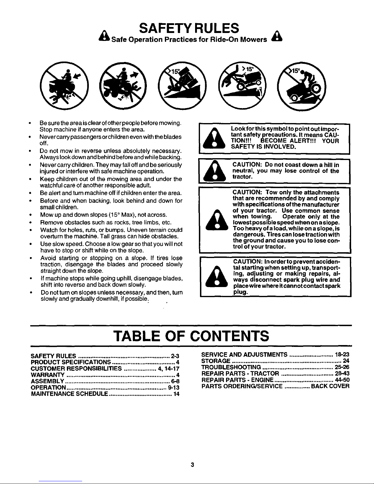
• Mow up and down slopes (15 ° Max), not across.
• Remove obstacles such as rocks, tree limbs, etc.
• Watch for holes, ruts, or bumps. Uneven terrain could
overturn the machine. Tall grass can hide obstacles.
• Use slow speed. Choose a low gear so that you will not
have to stop or shift while on the slope.
• Avoid starting or stopping on a slope. If tires lose
traction, disengage the blades and proceed slowly
straight down the slope.
• If machine stops while going uphill, disengage blades,
shift into reverse and back down slowly.
• Do not turn on slopes unless necessary, and then, turn
slowly and gradually downhill, if possible:
&
&
Look for this symbol to point out impor-
tant safety precautions. It means CAU-
TION!t! BECOME ALERT!!! YOUR
SAFETY IS INVOLVED.
CAUTION: Do not coast down a hill in
neutral, you may lose control of the
tractor.
i
CAUTION: Tow only the attachments
that are recommended by and comply
with specifications of the manufacturer
of your tractor. Use common sense
when towing. Operate only at the
lowest possible speed when ona slope.
Too heavy of a load, while ona slope, is
dangerou,_. Tires can lose traction with
the ground and cause you to lose con-
trol of your tractor.
CAUTION: In order to prevent acciden-
tal starting when setting up, transport-
ing, adjusting or making repairs, al-
ways disconnect spark plug wire and
place wire where itcannot contact spark
plug.
TABLE OF CONTENTS
SAFETY RULES ...................................................... 2-3
PRODUCT SPECIFICATIONS ..................................... 4
CUSTOMER RESPONSIBILITIES ................... 4, 14-17
WARRANTY ................................................................ 4
ASSEMBLY .............................................................. 6-8
OPERATION ........................................................... 9-13
MAINTENANCE SCHEDULE ..................................... 14
SERVICE AND ADJUSTMENTS .......................... 18-23
STORAGE ................................................................. 24
TROUBLESHOOTING .......................................... 25-26
REPAIR PARTS - TRACTOR ............................... 28-43
REPAIR PARTS - ENGINE ................................... 44-50
PARTS ORDERING/SERVICE ............... BACK COVER
3

PRODUCT SPECIFICATIONS
GASOLINE CAPACITY 3.5 GALLONS
AND TYPE: UNLEADED REGULAR
OILTYPE(API-SF/SG/SH): SAE 30 (above 32°F)
SAE 5W-30 (below 32°F)
OIL CAPACITY: 3 PINTS
SPARK PLUG: CHAMPION RJ19LM or J19LM
(GAP: ,030")
'ALVE CLEARANCE: INTAKE: .004"- ,006"
EXHAUST: .007" - ,009"
GROUND SPEED (MPH): FORWARD:
1st 1.2
2nd 1.5
3rd 2.4
4th 3.5
5th 4.8
6th 5.4
REVERSE: 1.5
TiRE PRESSURE: FRONT: 14 PSI
REAR: 10 PSI
CHARGING SYSTEM: 3 AMPS BATTERY
5 AMPS HEADLIGHTS
BATTERY: AMP/HR: 30
MIN. CCA: 240
CASE SIZE: U1R
BLADE BOLT TORQUE: 27-35 FT. LBS.
CONGRATULATIONS onyour purchase ofa Sears Tractor.
Ithas been designed, engineered andmanufactured to give
you the best possible dependability and performance.
Should you experience any problem you cannot easily
remedy, please contact your nearest authorized service
center/department. We have competent, well-trained tech-
nicians and the proper tools to service or repair this tractor.
Please read and retain this manual. The instructions will
enable you to assemble and maintain your tractor properly.
Always observe the "SAFETY RULES".
MAINTENANCE AGREEMENT
A Sears Maintenance Agreement is available on this prod-
uct. Contact your nearest Sears store for details.
CUSTOMER RESPONSIBILITIES
• Read and observe the safety rules.
• Follow a regular schedule inmaintaining, caring for and
using your tractor.
• Follow the instructions under "Customer Responsibili-
ties" and "Storage" sections of this owner's manual.
WARNING: This tractor isequipped with an internal com-
bustion engine and should not be used on or near any
unimproved forest-covered, brush-covered or grass-cov-
ered land unlessthe engine's exhaust system isequipped
with a spark arrester meeting applicable localor state laws
(if any). Ifa sparkarrester isused, itshouldbe maintained
ineffective working order by the operator.
A spark arrester for the muffler is available through your
nearest authorized service center/department (See RE-
PAIR PARTS section of this manual).
LIMITED TWO (2) YEAR WARRANTY ON CRAFTSMAN TRACTOR (RIDING EQUIPMENT)
For Two (2) years from date of purchase Sears Canada, Inc. will repair or replace at Sears option free of charge parts which
are defective as a result of material or workmanship.
FULL ONE (1) YEAR WARRANTY ON BA'I'rERY
For One (1) year from date of purchase, if any battery included with this riding equipment proves defective in matedal or
workmanship and our testing determines the battery will not hold a charge, Sears will replace the battery at no charge,
COMMERCIAL OR RENTAL USE
Warranty on Riding Equipment used for commercial or rental purposes is limited to ninety (90) days.
This Warranty does NOT cover:
1. Pre-delivery set-up.
2. Tire replacement or repair caused by punctures from outside objects (such as nails, thorns, stumps, or glass).
3. Expendable items which become worn during normal use, such as blades, spark plug, air cleaners and belts.
4. Repairs necessary because of operator abuse or negligence, including damaged jackshaft or mandrel and the
failure to operate and maintain the equipment according to the instructions contained in the Owner's Manual.
5. In Home service.
Warranty service is available by returning the Craftsman Riding Equipment to the nearest Sears Service Centre/Department in
Canada. This warranty applies only while this product is in use in Canada.
This warranty is in addition to any statutory warranty and does not exclude or limit legal dghts you may have but shall run
concurrently with applicable provincial legislation. Furthermore, some provinces do NOT allow limitation on how long an
implied warranty will last so the above limitations may not apply to you.
SEARS CANADA, INC., TORONTO, ONTARIO M5B 2B8
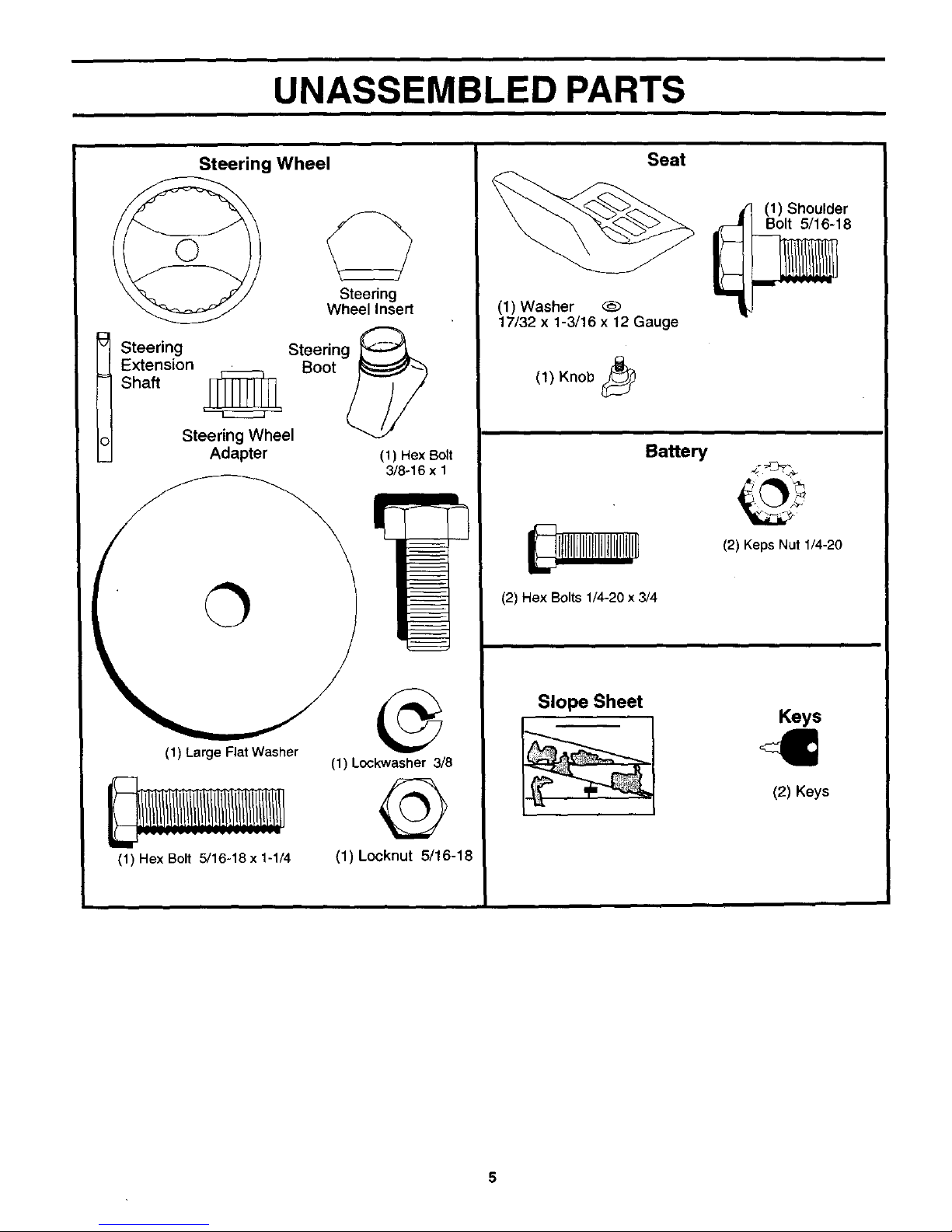
UNASSEMBLED PARTS
Steering Wheel
Steering
Wheel Insert
t teering
Extension
Shaft
Steering Wheel
Adapter (1) Hex Bolt
3/8-16 x 1
(1) Large Flat Washer
(1) Hex Bolt 5/16-18 x 1-1/4
(1) Lockwasher 3/8
(1) Locknut 5/16-18
Seat
(1) Washer
17/32 x 1-3/16 x 12 Gauge
(1) Knob
Ba_e_
(1) Shoulder
Bolt 5/16-18
(2) Keps Nut 1/4-20
Keys
(2) Keys
ASSEMBLY
Y_ur new tract_r has been assemb_ed at thefact_ry withexcepti_n _f th_se parts _eftunassemb_ed f_r shippingpurp_ses_ To
ensure safe and proper operation of your tractor all parts and hardware you assemble must be tightened securely. Use the
correct tools as necessary to insure proper tightness.
TOOLS REQUIRED FOR ASSEMBLY
A socket wrench set willmake assembly easier, Standard
wrench sizes are listed.
(1) 9/16" wrench Pliers
(2) 7/16" wrenches Tirepressure gauge
(2) 1/2" wrench Utility knife
When rightorleft hand is mentioned in this manual, it means
when you are in the operating position (seated behind the
steering wheel).
TO REMOVE TRACTOR FROM CARTON
UNPACK CARTON
• Remove all accessible loose parts and parts cartons
from carton.
• Cut, from top to bottom, along lines onall four corners
of carton, and lay panels flat.
• Check for any additional loose parts or cartons and
remove.
BEFORE REMOVING TRACTOR FROM
SKID
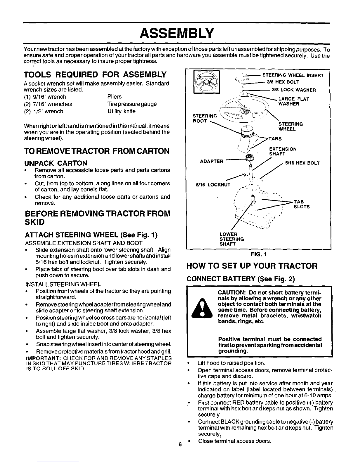
ATrACH STEERING WHEEL (See Fig. 1)
ASSEMBLE EXTENSION SHAFT AND BOOT
• Slide extension shaft onto lower steering shaft. Align
mounting holes inextension and lower shafts and install
5/16 hex bolt and Iocknut. Tighten securely.
• Pla_cetabs of steering boot over tab slots in dash and
push down to secure.
INSTALL STEERING WHEEL
• Position front wheels of the tractor so they are pointing
straight forward.
• Remove steering wheel adapter from steering wheel and
slide adapter onto steering shaft extension.
• Position steering wheel so cross bars are horizontal (left
to right) and slide inside boot and onto adapter.
• Assemble large flat washer, 3/8 lock washer, 3/8 hex
bolt and tighten securely.
Snap steedng wheelinsertintocenterof steering wheel
• Remove protective materials from tractor hood and grill.
IMPORTANT: CHECK FOR AND REMOVE ANY STAPLES
INSKID THAT MAY PUNCTURE TIRES WHERE TRACTOR
IS TO ROLL OFF SKID.
, _ STEERING WHEEL INSERT
• +4
_% ..___----- 3/8 HEX BOLT
3/8 LOCK WASHER
LOWER
STEERING
SHAFT
BOLT
FIG. 1
HOW TO SET UP YOUR TRACTOR
CONNECT BA'I-rERY (See Fig. 2)
&
CAUTION: Do not short battery termi-
nals by allowing a wrench or any other
object to contact both terminals at the
same time. Before connecting battery,
remove metal bracelets, wristwatch
bands, rings, etc.
Positive terminal must be connected
first to prevent sparking from accidental
grounding.
• Lift hood to raised position.
• Open terminal access doors, remove terminal protec-
tive caps and discard.
• If this battery is put into service after month and year
indicated on label (label located between terminals)
charge battery for minimum of one hour at 6-10 amps.
., First connect RED battery cable to positive (+) battery
terminal with hex bolt and keps nut as shown. Tighten
securely.
• Connect BLACK grounding cable to negative (-)battery
terminal with remaining hex bolt and keps nut. Tighten
securely;
Close terminal access doors.
ASSEMBLY
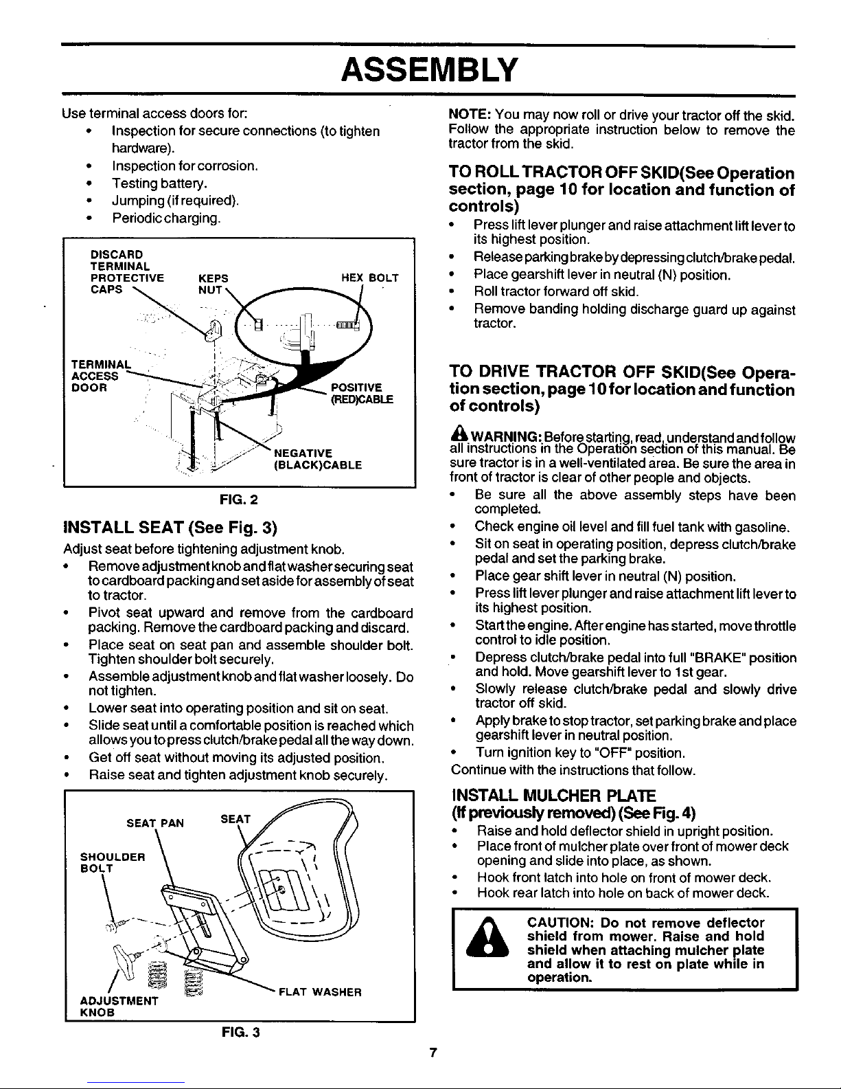
Use terminal access doors for:
• Inspection for secure connections (to tighten
hardware).
• Inspection for corrosion.
• Testing battery.
• Jumping (if required).
• Periodic charging.
DISCARD
TERMINAL
PROTECTIVE KEPS HEX BOLT
CAPS
TERMINAL
ACCESS
DOOR , POSITIVE
: (RED)CABLE
-_ NEGATIVE
_/ (BLACK)CABLE
FIG. 2
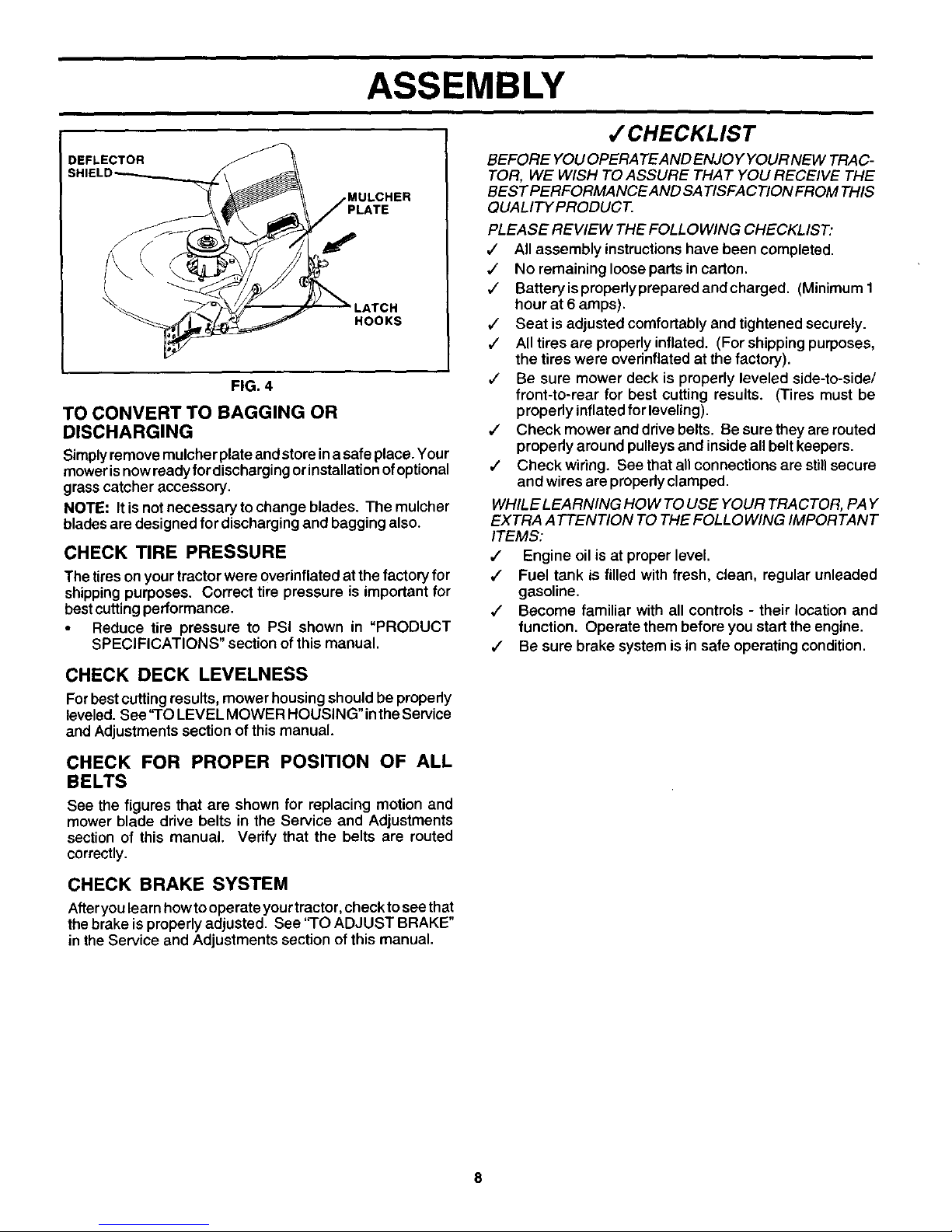
INSTALL SEAT (See Fig. 3)
Adjust seat before tightening adjustment knob.
• Remove adjustment knobandflatwasher secudngseat
to cardboard packing and set aside for assembly of seat
to tractor.
• Pivot seat upward and remove from the cardboard
packing. Remove the cardboard packing and discard.
• Place seat on seat pan and assemble shoulder bolt.
Tighten shoulder bolt securely.
Assemble adjustment knob and flat washer loosely. Do
not tighten.
• Lower seat into operating position and sit on seat.
• Slide seat until a comfortable position is reached which
allows you to press clutch/brake pedal all the way down.
Get off seat without moving its adjusted position.
• Raise seat and tighten adjustment knob securely.
SEAT PAN SE_TS_I
.o LOER \,,
_ FLAT WASHER
ADJUSTMENT
KNOB
NOTE: You may now roll or drive your tractor off the skid.
Follow the appropriate instruction below to remove the
tractor from the skid.
TO ROLL TRACTOR OFF SKID(See Operation
section, page 10 for location and function of
controls)
• Press lift lever plunger and raise attachment lift lever to
its highest position.
• Release parking brake bydepressing clutch/brake pedal.
• Place gearshift lever in neutral (N) position.
• Roll tractor forward off skid.
• Remove banding holding discharge guard up against
tractor.
TO DRIVE TRACTOR OFF SKID(See Opera-
tion section, page 10 for location and function
of controls)
_0AWARNING" Before starting,read understand andfo low
all instructions'inthe Operation sec{ionof thismanual. Be
sure tractor isin a well-ventilated area. Be sure the area in
front of tractor isclear of other people and objects.
• Be sure all the above assembly steps have been
completed.
• Check engine oil level and fill fuel tank with gasoline.
• Siton seat in operating position,depress clutch/brake
pedal and set the parking brake.
• Place gear shift lever in neutral (N) position.
• Press liftlever plungerand raise attachment liftlever to
its highest position.
• Startthe engine. Afterengine has started, movethrottle
controlto idleposition.
• Depress clutch/brake pedal intofull "BRAKE" position
and hold. Move gearshift lever to 1st gear.
• Slowly release clutch/brake pedal and slowly drive
tractor off skid.
• Apply brake to stop tractor,set parking brake and place
gearshift lever inneutral position.
• Turn ignitionkey to "OFF" position.
Continue with the instructionsthat follow.
INSTALL MULCHER PLATE
(If previously removed) (See Fig. 4)
• Raise and hold deflector shield in upright position.
• Place front of mulcher plate over front ofmower deck
opening and slide into place, asshown.
Hook front latchinto hole onfrontof mower deck.
• Hook rear latch into hole on back of mower deck.
CAUTION: Do not remove deflector
shield from mower. Raise and hold
shield when attaching mulcher plate
and allow it to rest on plate while in
operation.
FIG. 3
7
ASSEMBLY
DEFLECTOR
PLATE
HOOKS
FIG. 4
TO CONVERT TO BAGGING OR
DISCHARGING
Simply remove mulcher plate and store ina safe place. Your
moweris now ready fordischarging orinstallation of optional
grass catcher accessory,
NOTE: It isnot necessary to change blades. The mulcher
blades are designed for discharging and bagging also.
CHECK TIRE PRESSURE
The tires on yourtractor were overinflated at the factory for
shipping purposes. Correct tire pressure is important for
best cuttingperformance.
• Reduce tire pressure to PSi shown in "PRODUCT
SPECIFICATIONS" section of this manual.
CHECK DECK LEVELNESS
For best cutting results, mower housing should be properly
leveled. See "TO LEVEL MOWER HOUSING" inthe Service
and Adjustments section of this manual.
CHECK FOR PROPER POSITION OF ALL
BELTS
See the figures that are shown for replacing motion and
mower blade drive belts in the Service and Adjustments
section of this manual. Verify that the belts are routed
correctly.
CHECK BRAKE SYSTEM
Afferyou learn how to operate your tractor, check to see that
the brake is properly adjusted. See "TO ADJUST BRAKE"
in the Service and Adjustments section of this manual.
,/CHECKLIST
BEFORE YOU OPERATEAND ENJO YYOUR NEW TRAC-
TOR, WE WISH TO ASSURE THAT YOU RECEIVE THE
BEST PERFORMANCE AND SATISFACTION FROM THIS
QUALITYPRODUCT.
PLEASE REVIEW THE FOLLOWING CHECKLIST."
,/ All assembly instructionshave been completed.
,/ No remaining loose parts in carton.
,/ Batteryisproperlypreparedandcharged. (Minimum1
hour at 6 amps).
,/ Seat is adjusted comfortably and tightened securely.
,/ All tires are properly inflated. (For shipping purposes,
the tires were overinflated at the factory).
,/ Be sure mower deck is properly leveled side-to-side/
front-to-rear for best cutting results. (Tires must be
properly inflated for leveling).
,/ Check mower and drive belts. Be sure they are routed
properly around pulleys and inside all belt keepers.
,/ Check wiring. See that all connections are still secure
and wires are propedy clamped.
WHILE LEARNING HOW TO USE YOUR TRACTOR, PAY
EXTRA ATTENTION TO THE FOLLOWING IMPORTANT
ITEMS:
,/ Engine oil is at proper level.
,/ Fuel tank is filled with fresh, clean, regular unleaded
gasoline.
,/ Become familiar with all controls - their location and
function. Operate them before you start the engine.
,/ Be sure brake system is in safe operating condition.
OPERATION
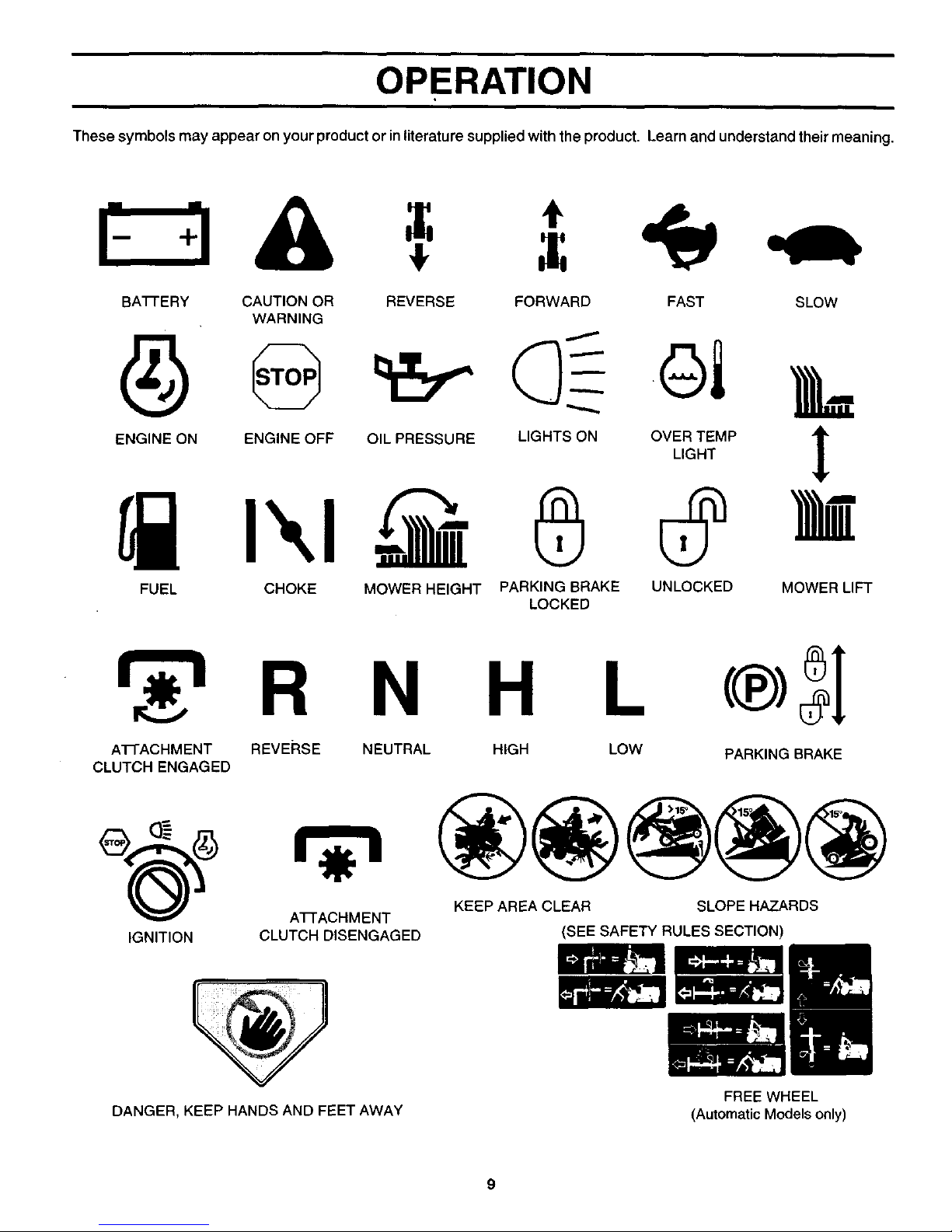
These symbols may appear on your product or in literature supplied with the product. Learn and understand their meaning.
BA'I-FE RY CAUTION OR REVERSE FORWARD FAST SLOW
WARNING
ENGINE ON ENGINE OFF OIL PRESSURE LIGHTS ON OVER TEMP
LIGHT
t
FUEL CHOKE MOWER HEIGHT PARKING BRAKE UNLOCKED MOWER LIFT
LOCKED
R N H
A'I-I-ACHMENT REVERSE
CLUTCH ENGAGED
IGNITION
A'I-FACHMENT
CLUTCH DISENGAGED
NEUTRAL HIGH LOW
PARKING BRAKE
KEEP AREA CLEAR SLOPE HAZARDS
(SEE SAFETYRULESSECTION)
DANGER, KEEP HANDS AND FEET AWAY
FREE WHEEL
(Automatic Models only)
9
OPERATION
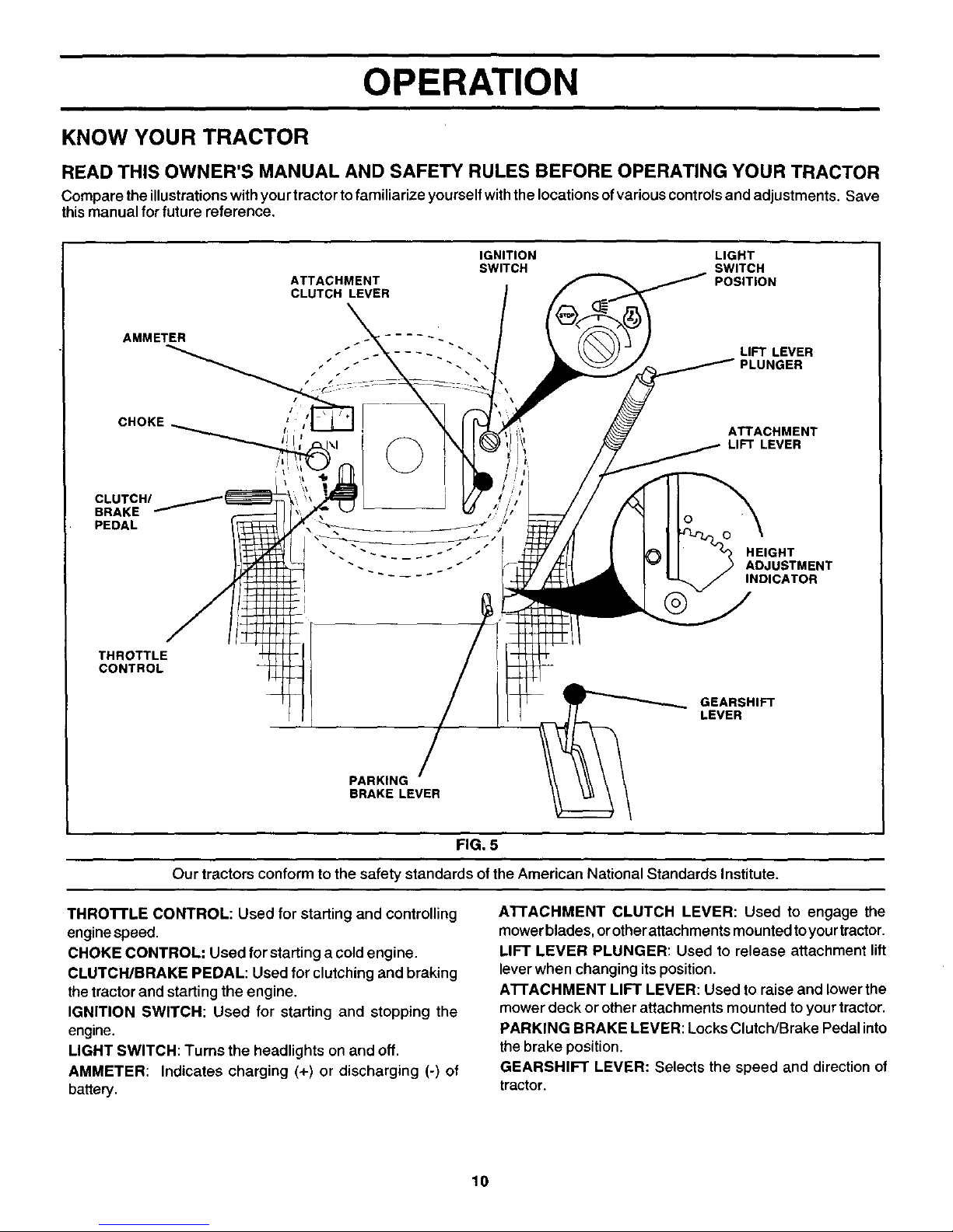
KNOW YOUR TRACTOR
READ THIS OWNER'S MANUAL AND SAFETY RULES BEFORE OPERATING YOUR TRACTOR
Compare the illustrationswithyour tractor to familiarize yourselfwiththe locations of variouscontrolsand adjustments. Save
thismanual for future reference.
ATTACHMENT
CLUTCH LEVER
IGNITION LIGHT
SWITCH SWITCH
POSITION
AMMETER
CHOKE_ _
CLUTCH/
BRAKE
PEDAL
LIFT LEVER
_GER
ATTACHMENT
LIFT LEVER
o \
o
HEIGHT
ADJUSTMENT
INDICATOR
THROTTLE
CONTROL
GEARSHIFT
LEVER
PARKING
BRAKE LEVER
FIG. 5
Our tractors conform to the safety standards ofthe American National Standards Institute.
THRO'n'LE CONTROL: Used for starting and controlling
engine speed.
CHOKE CONTROL: Used for startinga cold engine.
CLUTCH/BRAKE PEDAL: Used for clutching and braking
thetractor and starting the engine.
IGNITION SWITCH: Used for starting and stopping the
engine.
LIGHT SWITCH: Turns the headlights onand off.
AMMETER: Indicates charging (+) or discharging (-) of
battery.
ATTACHMENT CLUTCH LEVER: Used to engage the
mower blades, orother attachments mountedtoyourtractor.
LIFT LEVER PLUNGER: Used to release attachment lift
lever when changing itsposition.
ATFACHMENT LIFT LEVER: Used to raise and lower the
mower deck or other attachments mounted toyour tractor.
PARKING BRAKE LEVER: Locks Clutch/Brake Pedal into
the brake position.
GEARSHIFT LEVER: Selects the speed and directionof
tractor.
10
OPERATION
The operation of any tractor can result in foreign objects thrown into the eyes, which can
result in severe eye damage. Always wear safety glasses or eye shields while operating
your tractor or performing any adjustments or repairs. We recommend a wide vision
safety mask over spectacles or standard safety glasses.
I
HOW TO USE YOUR TRACTOR
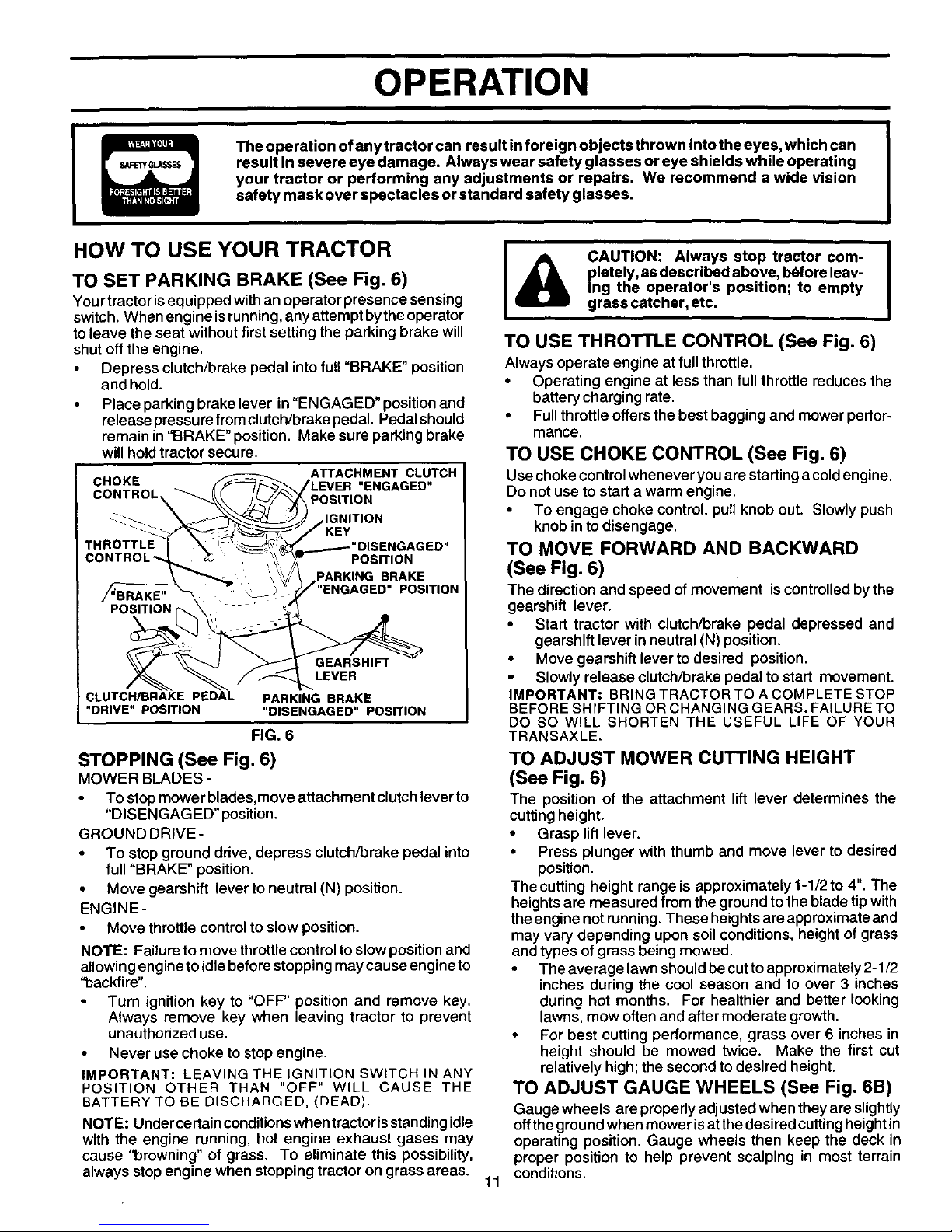
TO SET PARKING BRAKE (See Fig. 6)
Yourtractor is equipped withan operator presence sensing
switch. When engine isrunning,any attempt by the operator
to leave the seat without firstsetting the parking brake will
shut off the engine,
• Depress clutch/brake pedal into full "BRAKE" position
and hold.
• Place parking brake lever in "ENGAGED" positionand
release pressurefromclutch/brake pedal. Pedal should
remain in "BRAKE" position. Make sure parking brake
will holdtractor secure,
CHOKE
CO,T.OL
CLUTCH/BRAKE PEDAL
"DRIVE" POSITION
ATTACHMENT CLUTCH
tLEVER "ENGAGED"
POSIT ON
) IGNITION
J KEY
......---"DISENGAGED"
POSITION
PARKING BRAKE
/'"ENGAGED" POSITION
GEARSHIFT
LEVER
PARKING BRAKE
"DISENGAGED" POSITION
FIG. 6
STOPPING (See Fig. 6)
MOWER BLADES -
• To stop mower blades,move attachment clutch lever to
"DISENGAGED"position.
GROUND DRIVE-
• To stop ground drive, depress clutch/brake pedal into
full"BRAKE" position.
• Move gearshift lever toneutral (N) position.
ENGINE-
Move throttle controlto slow position.
NOTE: Failure tomove throttlecontrolto slow position and
allowing engineto idle before stoppingmay cause engine to
"backfire",
Turn ignition key to "OFF" position and remove key,
Always remove key when leaving tractor to prevent
unauthorized use.
• Never use choke to stop engine.
IMPORTANT: LEAVING THE IGNITION SWITCH IN ANY
POSITION OTHER THAN "OFF" WILL CAUSE THE
BATTERY TO BE DISCHARGED, (DEAD).
NOTE: Under certain conditions when tractor isstanding idle
with the engine running, hot engine exhaust gases may
cause "browning" of grass. To eliminate this possibility,
always stop engine when stopping tractor on grass areas.
I
I
CAUTION: Always stop tractor com- |
pletely, as described above, before leav-
I
ing the operator's position; to empty
grass catcher, etc.
TO USE THRO'B'LE CONTROL (See Fig. 6)
Always operate engine at fullthrottle.
• Operating engine at less than full throttle reduces the
battery charging rate.
• Full throttle offers the best bagging and mower perfor-
mance.
TO USE CHOKE CONTROL (See Fig. 6)
Use choke controlwhenever you are starting acold engine.
Do not use to start a warm engine,
• To engage Choke control,pull knob out. Slowly push
knob in to disengage,
TO MOVE FORWARD AND BACKWARD
(See Fig. 6)
The direction and speed of movement iscontrolledby the
gearshift lever.
• Start tractor with clutch/brake pedal depressed and
gearshift lever in neutral (N) position,
• Move gearshift lever to desired position.
• Slowly release clutch/brake pedal to start movement.
IMPORTANT: BRING TRACTOR TO A COMPLETE STOP
BEFORE SHIFTING OR CHANGING GEARS. FAILURE TO
DO SO WILL SHORTEN THE USEFUL LIFE OF YOUR
TRANSAXLE.
11
TO ADJUST MOWER CUTTING HEIGHT
(See Fig. 6)
The position of the attachment lift lever determines the
cutting height.
• Grasp liftlever.
• Press plunger with thumb and move lever to desired
position.
The cutting height range is approximately 1-1/2 to 4". The
heightsare measured from the ground to the blade tipwith
theengine notrunning, These heightsare approximate and
may vary depending upon soilconditions, height of grass
and types of grass being mowed.
• The average lawn should be cut to approximately 2-1/2
inches during the cool season and to over 3 inches
during hot months. For healthier and better looking
lawns, mow often and after moderate growth.
• For best cutting performance, grass over 6 inches in
height should be mowed twice. Make the first cut
relatively high; the second to desired height.
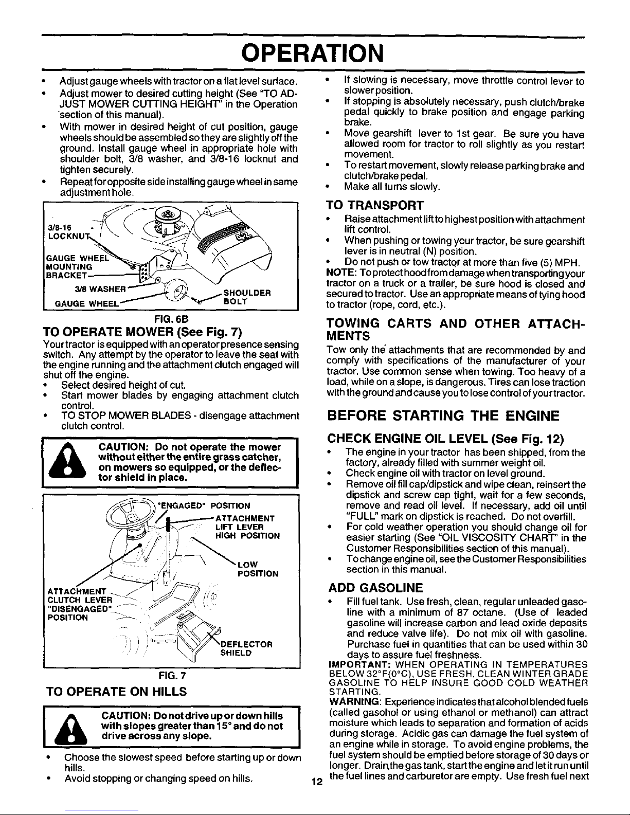
TO ADJUST GAUGE WHEELS (See Fig. 6B)
Gauge wheels are properly adjusted when they are slightly
off the ground when mower is atthe desired cutting height in
operating position. Gauge wheels then keep the deck in
proper position to help prevent scalping in most terrain
conditions.
OPERATION
• Adjust gauge wheels withtractor on a flat level surface. •
• Adjust mower to desired cutting height (See "TO AD-
JUST MOWER CUTTING HEIGHT" in the Operation
"sectionof this manual).
With mower in desired height of cut position, gauge •
wheels should be assembled so they are slightly off the
ground. Install gauge wheel in appropriate hole with
shoulder bolt, 3/8 washer, and 3/8-16 Iocknut and
tighten securely. •
Repeat for opposite side installinggauge wheel in same •
adjustment hole.
GAUGE WHEEL
BOLT
FIG. 6B
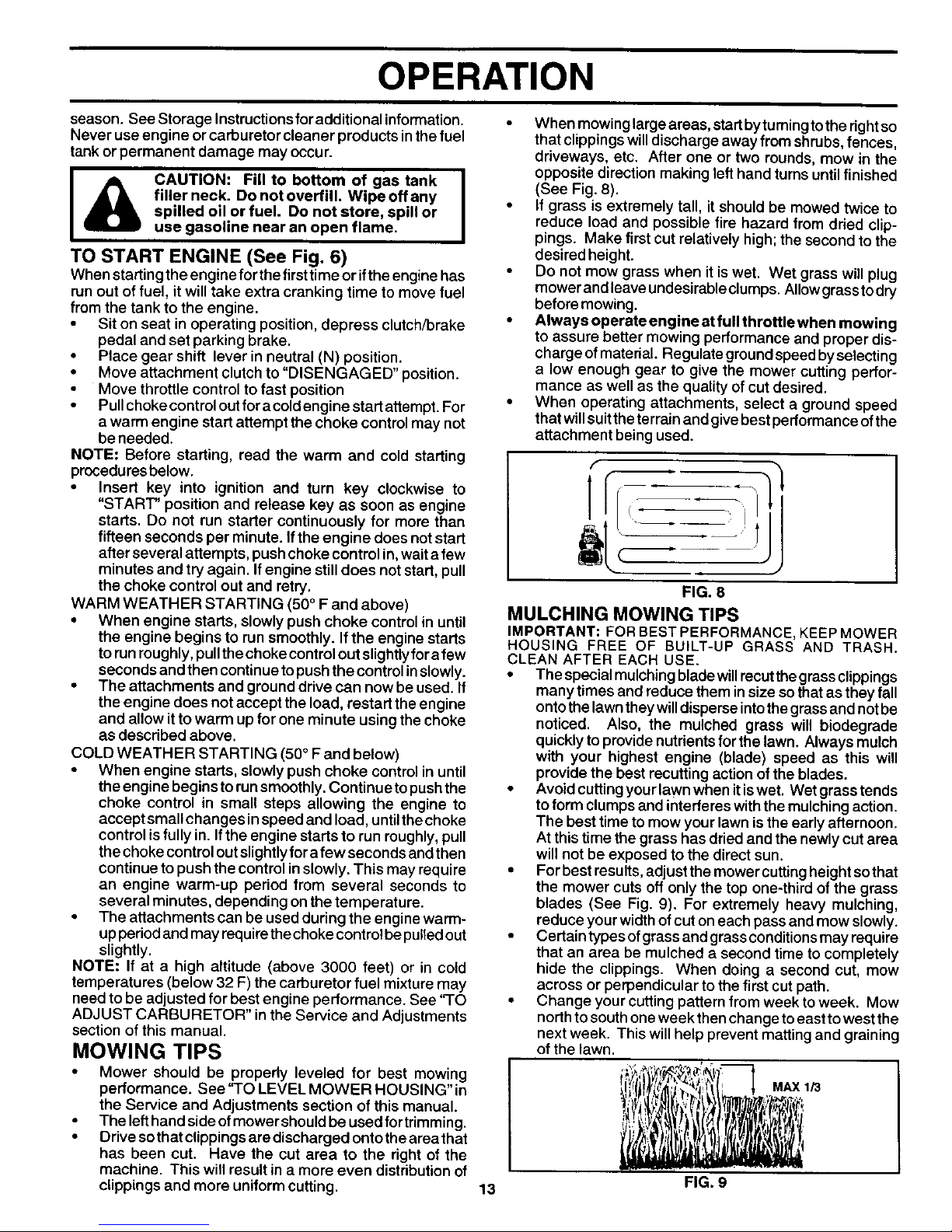
TO OPERATE MOWER (See Fig. 7)
Yourtractor isequipped withan operator presence sensing
switch. Any attempt by the operator to leave the seat with
theengine running andthe attachment clutch engaged will
shut off the engine.
• Select desired height of cut.
• Start mower blades by engaging attachment clutch
control.
• TO STOP MOWER BLADES - disengage attachment
clutch control.
&
CAUTION: Do not operate the mower I
without either the entire grass catcher,
I
on mowers so equipped, or the deflec-
tor shield in place.
"ENGAGED" POSITION
IMENT
: LIFT LEVER
HIGH POSITION
ATTACHMENT_
CLUTCH LEVER
"DISENGAGED" --"
POSITION
LOW
POSITION
" SHIELD
FIG. 7
TO OPERATE ON HILLS
I & CAUTION: DonotdriveupordownhUls I
with slopes greater than 15° and do not
drive across any slope.
• Choose the slowest speed before starting upor down
hills.
• Avoid stopping or changing speed on hills.
If slowing is necessary, move throttle control lever to
slower position.
If stopping is absolutely necessary, push clutch/brake
pedal quickly to brake position and engage parking
brake.
Move gearshift lever to 1st gear. Be sure you have
allowed room for tractor to roll slightly as you restart
movement.
To restart movement, slowly release parking brake and
clutch/brake pedal.
Make all turns slowly.
TO TRANSPORT
• Raise attachment lifttohighest position with attachment
lift control.
• When pushing or towing your tractor, be sure gearshift
lever is in neutral (N) position.
• Do not push or tow tractor at more than five (5) MPH.
NOTE: To protect hood from damage when transporting your
tractor on a truck or a trailer, be sure hood is closed and
secured to tractor. Use an appropriate means of tying hood
to tractor (rope, cord, etc.).
TOWING CARTS AND OTHER ATTACH-
MENTS
Tow only the"attachments that are recommended by and
comply with specifications of the manufacturer of your
tractor. Use common sense when towing. Too heavy of a
load, while on aslope, isdangerous. Tires can lose traction
with the ground and cause you to lose control of yourtractor.
BEFORE STARTING THE ENGINE
CHECK ENGINE OIL LEVEL (See Fig. 12)
• The engine in your tractor has been shipped, from the
factory, already filled with summer weight oil.
• Check engine oil with tractor on level ground.
• Remove oilfillcap/dipstick and wipeclean, reinsert the
dipstick and screw cap tight, wait for a few seconds,
remove and read oil level. If necessary, add oil until
"FULL" mark on dipstick is reached. Do notoverfill.
• For cold weather operation you should change oil for
easier starting (See "OIL VISCOSITY CHART" in the
Customer Responsibilities section of thismanual).
• To change engine oil,see the Customer Responsibilities
section inthis manual.
12
ADD GASOLINE
• Fillfuel tank. Use fresh, clean, regular unleaded gaso-
line with a minimum of 87 octane. (Use of leaded
gasoline will increase carbon and lead oxide deposits
and reduce valve life). Do not mix oil with gasoline.
Purchase fuel inquantities that can be used within 30
days to assure fuel freshness.
IMPORTANT: WHEN OPERATING IN TEMPERATURES
BELOW32°F(0°C), USE FRESH, CLEAN WINTER GRADE
GASOLINE TO HELP INSURE GOOD COLD WEATHER
STARTING.
WARNING: Experience indicates that alcohol blended fuels
(called gasohot or using ethanol or methanol) can attract
moisture which leads to separation and formation of acids
during storage. Acidic gas can damage the fuel system of
an engine while in storage. To avoid engine problems, the
fuel system should be emptied before storage of 30 claysor
longer. Drain,the gas tank, start the engine and let itrun until
the fuel lines and carburetor are empty. Use fresh fuel next
OPERATION
season. See Storage Instructionsforadditional information.
Never use engine or carburetor cleaner products in the fuel
tank or permanent damage may occur.
CAUTION: Fill to bottom of gas tank I
filler neck. Do not overfill. Wipe off any
I
spilled oil or fuel. Do not store, spill or
use gasoline near an open flame.
TO START ENGINE (See Fig. 6)
When startingthe engineforthe firsttime or ifthe engine has
runout of fuel, it will take extra cranking time to move fuel
from the tank to the engine.
• Sit on seat in operating position, depress clutch/brake
pedal and set parking brake.
• Place gear shift lever in neutral (N) position.
• Move attachment clutchto "DISENGAGED" position.
• Move throttle control to fast position
• Pullchoke controloutfor acold engine start attempt. For
a warm engine startattempt the choke controlmay not
beneeded.
NOTE: Before starting, read the warm and cold starting
proceduresbelow.
• Insert key into ignition and turn key clockwise to
"START" positionand release key as soon as engine
starts. Do not run starter continuously for more than
fifteen seconds per minute. Ifthe engine does not start
after several attempts, push choke control in,wait afew
minutes and try again. Ifengine still does notstart, pull
the choke control out and retry.
WARM WEATHER STARTING (50 ° F and above)
• When engine starts, slowly push choke control in until
the engine begins to runsmoothly. If the engine starts
torunroughly,pullthechoke controlout slightlyfor afew
seconds and then continue topushthe control inslowly.
• The attachments and grounddrive can now be used. If
the engine does notaccept the load, restart theengine
and allow itto warm up for one minute using the choke
as described above.
COLD WEATHER STARTING (50° F and below)
• When engine starts, slowlypush choke controlin until
the engine begins torunsmoothly.Continue topushthe
choke control in small steps allowing the engine to
accept small changes inspeed and load, untilthechoke
control is fully in. If the engine starts to run roughly, pull
the choke controloutslightlyfor afew seconds and then
continue to pushthe control in slowly. This may require
an engine warm-up period from several seconds to
several minutes, depending onthe temperature.
• Theattachmentscanbeusedduringtheenginewarm-
upperiodand may requirethe choke controlbe pulledout
slightly.
NOTE: If at a high altitude (above 3000 feet) or in cold
temperatures (below 32 F) the carburetor fuel mixture may
need tobe adjusted for best engine performance. See "TO
ADJUST CARBURETOR" inthe Service and Adjustments
section of this manual.
MOWING TIPS
• Mower should be properly leveled for best mowing
performance. See "TO LEVEL MOWER HOUSING" in
the Service and Adjustments section of this manual.
• The lefthandside ofmower shouldbe used fortrimming.
• Drive sothat clippingsare discharged ontothe areathat
has been cut. Have the cut area to the right of the
machine. This will result in a more even distributionof
clippings and more uniform cutting.
When mowinglarge areas, startbytumingtothe right so
thatclippingswilldischarge away from shrubs,fences,
driveways, etc. After one or two rounds, mow in the
opposite direction making left hand turnsuntilfinished
(See Fig. 8).
• If grass is extremely tall, itshould be mowed twice to
reduce load and possible fire hazard from dried clip-
pings. Make first cutrelatively high; the second to the
desired height.
• Do notmow grass when itis wet. Wet grasswill plug
mower and leaveundesirableclumps. Allow grasstodry
beforemowing.
• Always operate engine at full throttle when mowing
to assure better mowing performance and proper dis-
charge of material. Regulate groundspeed byselecting
a low enough gear to give the mower cutting perfor-
mance as wellas the quality of cut desired.
• When operating attachments, select a ground speed
thatwillsuittheterrain and givebest performance of the
attachment being used.
FIG. 8
MULCHING MOWING TIPS
IMPORTANT: FOR BEST PERFORMANCE, KEEP MOWER
HOUSING FREE OF BUILT-UP GRASS AND TRASH.
CLEAN AFTER EACH USE.
• The specialmulching bladewUlrecutthegrassclippings
many times and reduce them insize sothat as they fall
ontothe lawntheywilldisperse intothegrassand notbe
noticed. Also, the mulched grass will biodegrade
quickly to providenutrients forthe lawn. Always mulch
with your highest engine (blade) speed as this will
provide the best recutting action ofthe blades.
• Avoid cuttingyour lawnwhen itiswet. Wet grasstends
to form clumpsand interfereswith the mulchingaction.
The best time to mow your lawn isthe early afternoon.
At this time the grass has dried and the newly cut area
will not be exposed to the direct sun.
• For best results, adjust the mower cutting height so that
the mower cuts off only the top one-third of the grass
blades (See Fig. 9). For extremely heavy mulching,
reduce your width of cut oneach pass and mow slowly.
• Certain types of grass and grass conditions may require
that an area be mulched a second time to completely
hide the clippings. When doing a second cut, mow
across or perpendicular to the first cut path.
• Change your cutting pattern from week to week. Mow
north to south one week then change to east to west the
next week. This will help prevent matting and graining
of the lawn.
MAX 1/3
13
FIG. 9
CUSTOMER RESPONSIBILITIES
AS YOU COMPLETE f__-_'_ _._'_'_"
REGOL RSERVlCE OATES
Check Brake Operation _V' I_
Check Tire Pressure
i Check Operator Presence and
T ' Interlock Systems I_
R Check for Loose Fasteners V' V'7 V'
A Sharpen/Replace Mower Blades _4
T Lubrication Chart if
0 ' Check Battery Level
R Clean Battery and Terminals I_
Check Transaxle Cooling If
Adjust Blade Belt(s) Tension V'5
Adjust Motion Drive Belt(s) Tension li/s
Check Engine Oil Level I_ I_
Change Engine Oil li_t2,: I_
i
Clean Air Screen
Inspect Muffler/Spark Arrester li/'
Replace Oil Filter (If 11_1.2
equipped)
E Clean Engine Cooling Fins V'2
Replace Spark Plug _2 I/'
Replace Air Filter Paper Cartridge
Replace Fuel Filter
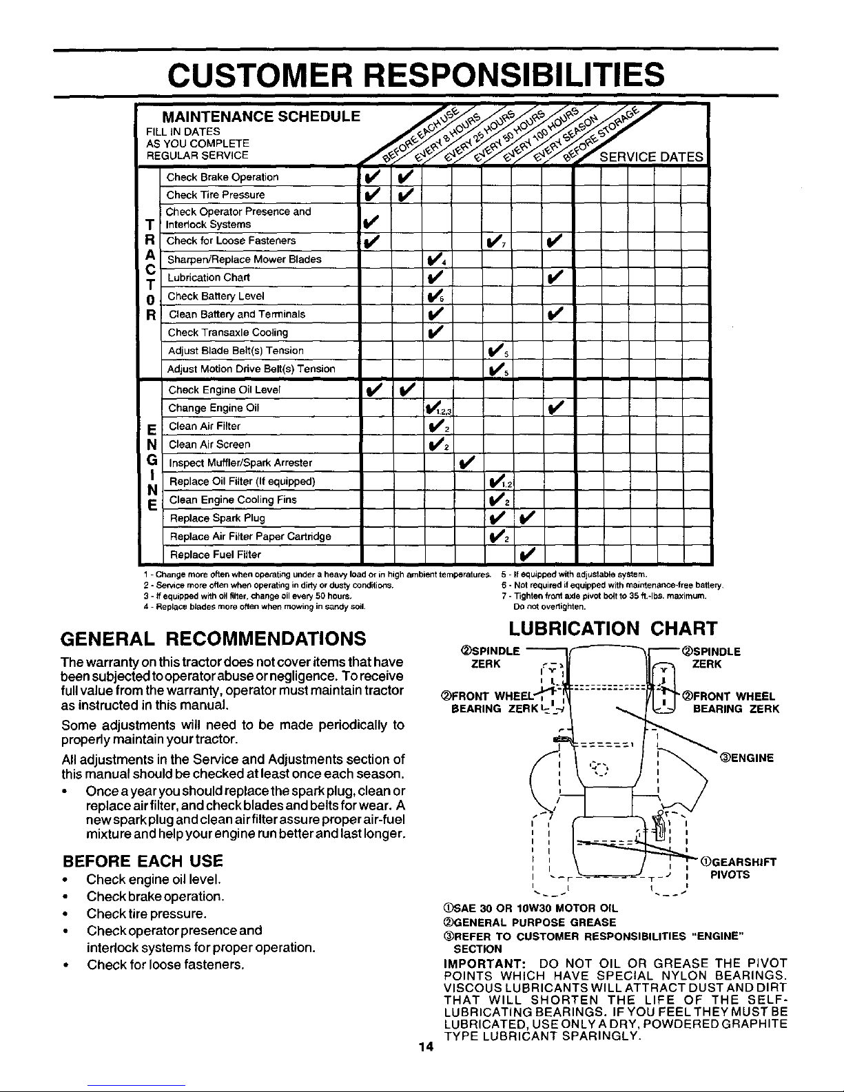
1 - Change more often when operating under a heavy load or in high ambient temperatures. 5 - If equipped with adjuStable system,
2 - Se_ce more often when operating in dirty or dusty COnditions, 6 o NOt required it equipped with maJoten_nce-free bakery,
S - ff equipped with oi_filter, change oil every 50 hours. 7 - Tighten front axle pivOt bott to 35 ft.°lbs, maximum.
4 - Replace blede$ more often when mowing in sandy soil. DO not overltghten.
GENERAL RECOMMENDATIONS
The warranty onthistractor does notcover items that have
been subjected to operator abuse or negligence. To receive
full value from the warranty, operator must maintain tractor
as instructed in this manual.
Some adjustments will need to be made periodically to
properly maintain your tractor.
All adjustments in the Service and Adjustments section of
this manual should be checked at least once each season.
• Once a year you should replace the spark plug, clean or
replace air filter, and check blades and belts for wear. A
new spark plug and clean airfilter assure proper air-fuel
mixtu re and help your engine run better and last longer.
BEFORE EACH USE
• Check engine oil level.
Check brake operation.
• Check tire pressure.
• Check operator presence and
interlock systems for proper operation.
• Check forloose fasteners.
LUBRICATION CHART
(_SPINDLE
ZERK i_'_ _ ZERK
_)FRONT
BEARING ZERK_
"_)FRONT WHEEL
BEARING ZBRK
14
i I (_GEARSHIFT
---' I PIVOTS
(_)SAE 30 OR 10W30 MOTOR OIL
(_GENERAL PURPOSE GREASE
@REFER TO CUSTOMER RESPONSIBILITIES "ENGINE"
SECTION
IMPORTANT: DO NOT OIL OR GREASE THE PIVOT
POINTS WHICH HAVE SPECIAL NYLON BEARINGS.
VISCOUS LUBRICANTS WILL ATTRACT DUST AND DIRT
THAT WILL SHORTEN THE LIFE OF THE SELF-
LUBRICATING BEARINGS. IF YOU FEEL THEY MUST BE
LUBRICATED, USE ONLY A DRY, POWDERED GRAPHITE
TYPE LUBRICANT SPARINGLY.
CUSTOMER RESPONSIBILITIES
TRACTOR
Always observe safety rules when performing any mainte-
nance.
BRAKE OPERATION
Iftractor requires morethan six (6)feet stopping distance at
high speed in highest gear, then brake must be adjusted.
(See "TO ADJUST BRAKE" inthe Service and Adjustments
section of this manual).
TIRES
• Maintain preper airpressure inalltires (See"PRODUCT
SPECIFICATIONS" section ofthis manual).
• Keep tires free of gasoline, oil, or insect controlchemi-
cals which can harm rubber.
• Avoid stumps, stones, deep ruts, sharp objects and
other hazards that may cause tire damage.
NOTE: To seal tire punctures and prevent flat tires due to
slow leaks, tire sealant may be purchased from your local
parts dealer. Tire sealant also prevents tire dry rot and
corrosion.
OPERATOR PRESENCE SYSTEM
Be sure operator presence and interlocksystems are work-
ingproperly. Ifyourtractor doesnot function as described,
repair the problem immediately.
• The engine should not start unless the clutch/brake
pedal isfully depressed and attachement clutch control
isin the disengaged position.
• When the engineisrunning, anyattempt by the operator
to leave the seat without first setting the parking brake
should shut offthe engine.
• When theengine isrunning and the attachment clutchis
engaged, any attempt bythe operator to leave the seat
should shut offthe engine.
• The attachment clutchshouldnever operate unlessthe
operator isin the seat.
BLADE CARE
Forbest results mower blades must bekept sharp. Replace
bent or damaged blades.
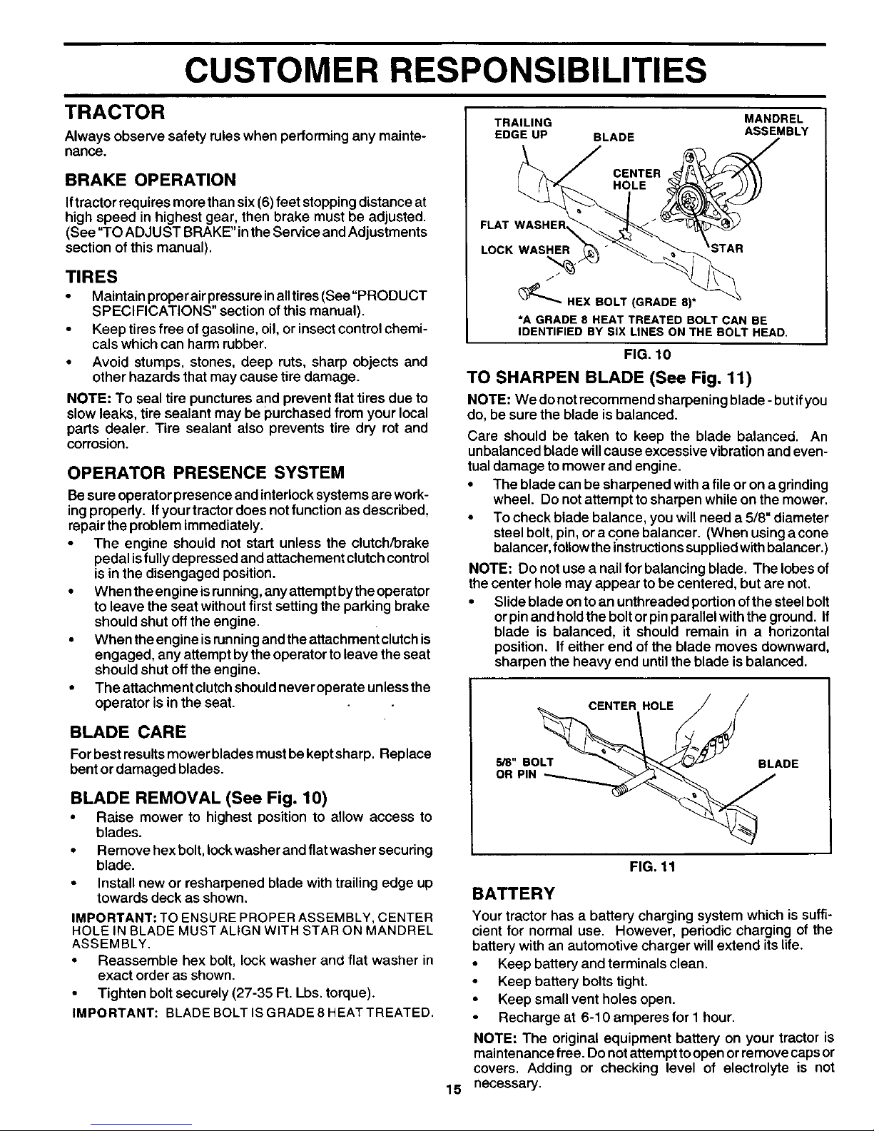
BLADE REMOVAL (See Fig. 10)
• Raise mower to highest position to allow access to
blades.
• Remove hexbolt, Iockwasher and flat washer securing
blade.
• Install new or resharpened blade with trailing eclge up
towards deck as shown.
IMPORTANT: TO ENSURE PROPER ASSEMBLY, CENTER
HOLE IN BLADE MUST ALIGN WITH STAR ON MANDREL
ASSEMBLY.
• Reassemble hex bolt, lock washer and flat washer in
exact order as shown.
Tighten bolt securely (27-35 Ft. Lbs. torque).
IMPORTANT: BLADE BOLT IS GRADE 8 HEAT TREATED.
TRAILING
EDGE UP BLADE
MANDREL
ASSEMBLY
CENTER
HOLE
FLAT WASHER_
LOCK WASHER
_HEX BOLT (GRADE 8)*
*A GRADE 8 HEAT TREATED BOLT CAN BE
IDENTIFIED BY SIX LINES ON THE BOLT HEAD,
FIG. 10
TO SHARPEN BLADE (See Fig. 11)
NOTE: We donet recommend sharpening blade -butifyou
do, be sure the blade is balanced.
Care should be taken to keep the blade balanced. An
unbalanced blade will cause excessive vibration and even-
tual damage to mower and engine.
• The blade can be sharpened with a file or on a grinding
wheel. Do not attempt to sharpen while on the mower.
• To check blade balance, you will need a 5/8" diameter
steel bolt, pin, or a cone balancer. (When using a cone
balancer, follow the instructions supplied with balancer.)
NOTE: Do not use a nail for balancing blade. The lobes of
the center hole may appear to be centered, but are not.
• Slide blade onto an unthreaded portion ofthe steelbolt
or pin and holdthe boltor pinparallelwith the ground. If
blade is balanced, it should remain in a hodzontal
position. If either end of the blade moves downward,
sharpen the heavy end untilthe blade is balanced.
15
CENTER HOLE J /
5/8" BO_ BLADE
OR PIN__
FIG. 11
BATTERY
Your tractor has a battery charging system which is suffi-
cient for normal use. However, periodic charging of the
battery with an automotive charger will extend itslife.
• Keep battery and terminals clean.
• Keep battery bolts tight.
• Keep small vent holes open.
Recharge at 6-10 amperes for 1 hour.
NOTE: The original equipment battery on your tractor is
maintenance free. Do not attempt to open or remove caps or
covers. Adding or checking level of electrolyte is not
necessary.

CUSTOMER RESPONSIBILITIES
TO CLEAN BAI-FERY AND TERMINALS
Corrosion and dirt on the battery and terminals can cause the
battery to "leak" power.
• Removeterminal guard.
• Disconnect BLACK battery cable first then RED battery
cable and remove battery from tractor.
• Rinse the battery with plain water and dry.
• Clean terminals and battery cable ends with wire brush
until bright.
• Coat terminals with grease or petroleum jelly.
• Reinstall battery (See "CONNECT BATTERY" in the
Assembly Section of this manual).
V-BELTS
Check V-belts for deterioration andwear after 100 hours of
operation and replace if necessary. The belts are not
adjustable. Replace belts ifthey begin to slipfrom wear.
TRANSAXLE COOLING
Keeptransaxle free frombuild-up ofdirtand chaffwhichcan
restdct cooling.
ENGINE
LUBRICATION
Only use high quality detergent oil rated with API service
classification SF, SG or SH. Select the oil's SAE viscosity
grade according to your expected operating temperature.
SAE VISGOSITY GRADES
-20 o 0 o 30 ° 32 = 40 ° 60 ° 80 ° 100 _
-30 ° -20 ° -10 ° 0 ° 10" 30 ° 30 ° 40"
TEMPERATURE RANGE ANTICIPATED BEFORE NEXT OIL CHANGE
NOTE: Although multi-viscosity oils (5W30, 10W30 etc.)
improve starting in cold weather, these multi-viscosity oils
willresult in increased oil consumption when used above
32°F. Check your engine oillevel morefrequently to avoid
possibleengine damage from runninglow on oil.
Change the oilafter every 25 hours of operation or at least
oncea year if the tractor isnot usedfor 25 hours inone year.
Checkthe crankcase oillevel before starting the engine and
after each eight (8) hours of operation. Tighten oilfill cap/
dipsticksecurely each time you check the oil level.
TO CHANGE ENGINE OIL (See Fig. 12)
Determine temperature range expected before oil change.
All oil must meet API service classification SF, SG or SH.
• Be sure tractor is on level surface.
• Oil will drain more freely when warm.
• Catch oilin a suitable container.
Remove oil fill cap/dipstick. Be careful not to allow dirt
to enter the engine when changing oil.
• Remove drain plug.
After oil has drained completely, replace oil drain plug
and tighten securely.
16
• Refill engine withoil through oil fill dipstick tube. Pour
slowly. Do not overfill. For approximate capacity see
"PRODUCT SPECIFICATIONS" sectionofthis manual.
• Use gauge on oilfillcap/dipstick for checkinglevel. Be
sure dipstick cap is tightened securely for accurate
reading. Keep oilat "FULL" line on dipstick.
FIG. 12
ENGINE COOLING FINS (See Fig. 13)
Remove any dust, dirt or oil from engine cooling fins to
prevent engine damagefrom overheating. Airguide covers
must be removed. Remove sidepanels and hood (See 'q'O
REMOVE HOOD AND GRILL ASSEMBLY" inthe Service
and Adjustments section of thismanual).
ENGINE R,
COOLING FINS
/
AIR GUIDE COVER (BOTH SIDES)
FIG. 13
CLEAN AIR SCREEN (See Fig. 13)
Air screen must be kept free of dirt and chaff to prevent
engine damage fromoverheating. Clean withawirebrushor
compressed airto remove dirt and stubborn dried gum fibers,
 Loading...