

Page 1

OWNER’S
MANUAL
MODEL NO.
944.528398
Caution:
Read and follow
ail Safety Rules
and instructions
Before Operating
This Equipment
Sears Canada, Inc., Toronto, Ontario MSB 2B8
1350 SERIES B&S ENGINE
27" TWO^STAGE
POWER-PROPELLED
SNOW THROWER
* Assembly
* Operation
* Maintenance
* Service and Adjustments
* Repair Parts
Page 2

IMPORTANT
Safe Operation Practices for Walfc-Behind Snow Throwers
This snow thrower is capabie of amputating hands and feet and throwing objects,
Faiiure to observe the foiiowing safety instructions couid resuit in serious injury.
Look for this symbol to point out Im
portant safety precautions. It means
A
A
A
CAUTION!!! BECOMEALERT!!! YOUR
SAFETY IS INVOLVED.
WARNING: Always disconnect spark
plug wire and place It where It cannot
contact plug In order to prevent acci
dental starting when setting up, trans
porting, adjusting or making repairs.
WARNING: This snow thrower Is for
use on sidewalks, driveways and other
ground level surfaces. Caution should
be exercised while using on sloping sur
faces. Do not use snow thrower on
surfaces above ground level such as
roofs of residences, garages, porches
or other such structures or buildings.
Training
Read, understand and foiiow aii instructions on the
machine and in the manuai(s) before operating this
unit. Be thoroughiy famiiiar with the controis and the
proper use of the equipment. Know how to stop the
unit and disengage the controis quickiy.
Never aiiow chiidren to operate the equipment. Never
aiiow aduits to operate the equipment without proper
instruction.
3, Keep the area of operation ciear of aii persons, par-
ticuiariy smaii chiidren,
4, Exercise caution to avoid siipping or faiiing, especiaiiy
when operating the snow thrower in reverse.
Preparation
1, Thoroughiy inspect the area where the equipment is
to be used and remove aii doormats, sieds, boards,
wires, and other foreign objects,
2, Disengage aii ciutches and shift into neutrai before
starting the engine (motor),
3, Do not operate the equipment without wearing adequate
winter garments. Avoid ioose fitting ciothing that can
get caught in moving parts. Wear footwear that wiii
improve footing on siippery surfaces,
4, Handle fuei with care; it is highiy fiammabie
(a) Use an approved fuei container,
(b) Never add fuei to a running engine or hot en
gine,
(c) Fiii fuei tank outdoors with extreme care. Never fiii
fuei tank indoors,
(d) Never fiii containers inside a vehicie or on a truck
or traiier bed with a piastic iiner, Aiways piace
containers on the ground, away from your vehicie,
before fiiiing,
(e) When practicai, remove gas-powered equipment
from the truck or trailer and refuel it on the ground.
If this is not possibie, then refuei such equipment
on a traiier with a portabie container, rather than
from a gasoiine dispenser nozzie.
WARNING: Snow throwers have ex
posed rotating parts, which can cause
severe Injury from contact, or from ma
terial thrown from the discharge chute.
A
A
A
(f) Keep the nozzie in contact with the rim of the fuei
(g) Replace gasoline cap securely and wipe up spilled
(h) If fuel is spilled on clothing, change clothing im
5, Use extension cords and receptacles as specified by
the manufacturer for all units with electric drive motors
or electric starting motors,
6, Adjust the collector housing height to clear gravel or
crushed rock surface,
7, Never attempt to make any adjustments while the
engine (motor) is running (except when specifically
recommended by manufacturer),
8, Always wear safety glasses or eye shields during op
eration or while performing an adjustment or repair to
protect eyes from foreign objects that may be thrown
from the machine.
Keep the area of operation clear of all
persons, small children and pets at all
times Including startup.
CAUTION: Muffler and other engine
parts become extremely hot during
operation and remain hot after engine
has stopped. To avoid severe burns on
contact, stay away from these areas.
WARNING: Engine exhaust, some of
Its constituents, and certain vehicle
components contain or emit chemi
cals known to the State of California
to cause cancer and birth defects or
other reproductive harm.
tank or container opening at aii times, until refuel
ing is complete. Do not use a nozzle lock-open
device,
fuel,
mediately,
Operation
1, Do not put hands or feet near or under rotating parts.
Keep clear of the discharge opening at all times,
2, Exercise extreme caution when operating on or cross
ing gravel drives, walks, or roads. Stay alert for hidden
hazards or traffic,
3, After striking a foreign object, stop the engine (motor),
remove the wire from the spark plug, disconnect the
cord on electric motors, thoroughly inspect the snow
throwerfor any damage, and repair the damage before
restarting and operating the snow thrower,
4, If the unit should start to vibrate abnormally, stop the
engine (motor) and check immediately for the cause.
Vibration is generally a warning of trouble,
5, Stop the engine (motor) whenever you leave the oper
ating position, before unclogging the collector/impeller
housing or discharge chute, and when making any
repairs, adjustments or inspections.
Page 3

6, When cleaning, repairing or inspecting the snow thrower,
stop the engine and make certain the collector/impeller and all moving parts have stopped. Disconnect
the spark plug wire and keep the wire away from the
plug to prevent someone from accidentally starting the
engine,
7, Do not run the engine indoors, except when starting
the engine and for transporting the snow thrower in or
out of the building. Open the outside doors; exhaust
fumes are dangerous,
8, Exercise extreme caution when operating on slopes,
9, Never operatethe snow thrower without proper guards,
and other safety protective devices in place and work
ing.
10, Never direct the discharge toward people or areas
where property damage can occur. Keep children and
others away,
11, Do not overload the machine capacity by attempting
to clear snow at too fast a rate,
12, Never operate the machine at high transport speeds
on slippery surfaces. Look behind and use care when
operating in reverse,
13, Disengage power to the collector/impeller when snow
thrower is transported or not in use,
14, Use only attachments and accessories approved by
the manufacturer of the snow thrower (such as wheel
weights, counterweights, or cabs),
15, Never operate the snow thrower without good visibility
or light. Always be sure ofyourfooting, and keep a firm
hold on the handles. Walk; never run,
16, Never touch a hot engine or muffler.
Clearing a Clogged Discharge Chute
Hand contact with the rotating impeller inside the discharge
chute is the most common cause of injury associated with
snow throwers. Never use your hand to clean out the dis
charge chute. To clear the chute:
1, SHUT THE ENGINE OFF!
2, Wait 10 seconds to be sure the impeller blades have
stopped rotating.
3, Always use a clean-out tool, not your hands.
Maintenance and Storage
1, Check shear bolts and other bolts at frequent intervals
for proper tightness to be sure the equipment is in safe
working condition,
2, Never store the machine with fuel in the fuel tank
inside a building where ignition sources are present
such as hot water heaters, space heaters, or clothes
dryers. Allow the engine to cool before storing in any
enclosure,
3, Always refer to operator’s manual for important details
if the snow thrower is to be stored for an extended
period,
4, Maintain or replace safety and instruction labels, as
necessary,
5, Run the machine a few minutes after throwing snow
to prevent freeze-up of the collector/impeller.
SAFETY RULES
PRODUCT SPECIFICATIONS
CUSTOMER RESPONSIBILITIES
ASSEMBLY / PRE-OPERATION
OPERATION
MAINTENANCE SCHEDULE
............................................................
.........................................
................................................................
.........................................
TABLE OF CONTENTS
...................................
..................................
2-3
4
4
5-8
9-14
15
MAINTENANCE.........................................................15-16
SERVICE AND ADJUSTMENTS...............................17-19
STORAGE.......................................................................20
TROUBLESHOOTING....................................................21
REPAIR PARTS.........................................................22-45
WARRANTY....................................................................46
Page 4

CONGRATULATIONS on your purchase of a new snow
thrower. It has been designed, engineered and manufac
tured to give best possibie dependabiiity and performance,
Shouid you experience any probiem you cannot easily
remedy, please contact your nearest authorized service
center. We have competent, weii-trained technicians and
the proper toois to service or repair this unit,
Piease read and retain this manuai. The instructions wili
enabie you to assembie and maintain your snow thrower
properiy, Aiways observe the “SAFETY RULES”,
SERIAL NUMBER:
DATE OF PURCHASE:
PRODUCT SPECIFICATIONS
Gasoline Capacity 3,0 Ouarts (2,84 Liters)
and Type: Unieaded Reguiar oniy
Oil Type SAE 5W-30 or 10W-30
(API SG-SL): Synthetic SAE 5W-30
Oil Capacity: 28 Ounces (0,8 Liters)
Spark Plug: Champion RJ19LM
Gap: 0,030" (0,762 mm)
THEMODELANDSERIALNUMBERSWILLBE FOUND
ONADECALATTACHEDTOTHEREAROFTHESNOW
THROWER HOUSING,
YOU SHOULD RECORD BOTH SERIALNUMBER AND
DATE OF PURCHASE AND KEEP IN A SAFE PLACE
FOR FUTURE REFERENCE,
CUSTOMER RESPONSIBILITIES
• Read and observe the safety rules,
• Follow a regular schedule in maintaining, caring for
and using your snow thrower,
• Foiiow the instructions under “Maintenance” and “Stor
age” sections of this owner’s manuai.
Page 5

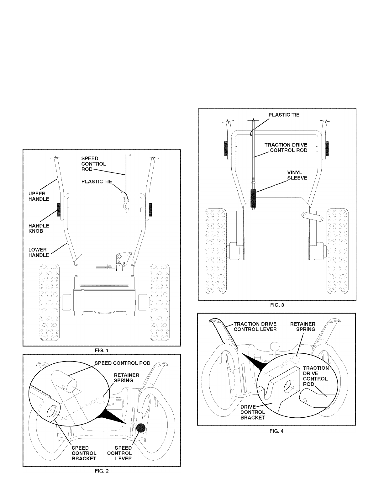
PARTS PACKED SEPARATELY IN CARTON
(2) FLAT WASHERS
(2) CARRIAGE BOLTS
3/8-16x2.25
ASSEMBLY / PRE-OPERATION
Read these Instructions and this manual In Its entirety
before you attempt to assemble or operate your new
snow thrower. Reading the entire manual will familiar
ize you with the unit, which will assist you In assembly,
operation and maintenance of the product.
Your new snow thrower has been assembled at the factory
with the exception of those parts left unassembled for ship
ping purposes. All parts such as nuts, washers, bolts, etc,,
necessary to complete the assembly have been placed in
the parts bag. To ensure safe and proper operation of your
snow thrower, all parts and hardware you assemble must
be tightened securely. Use the correct tools as necessary
to ensure proper tightness,
REMOVE SNOW THROWER FROM CARTON
1, Remove all accessible loose parts and parts boxes
from carton.
(2) HANDLE KNOBS
2, Cut down all four corners of carton and lay panels flat,
3, Remove the two (2) screws securing the auger housing
to the pallet,
4, Remove all packing materials except plastictie holding
speed control rod to lower handle,
5, Remove the two (2) plastic ties securing the upper
handle to the pallet,
6, Remove snow thrower from carton and check carton
thoroughly for additional loose parts,
HOW TO SET UP YOUR SNOW THROWER
TOOL BOX (See Fig. 10)
A toolbox is provided on your snow thrower. The toolbox is
located on top of the belt cover. Store the extra shear bolts,
nuts and multi-wrench provided in parts bag in the toolbox.
Page 6
ASSEMBLY / PRE-OPERATION
NOTE: The multi-wrench may be used for assembly of the
chute rotator head to snowthrower and making adjustments
to the skid plates,
UNFOLD UPPER HANDLE
1, Raise upper handle to the operating position and
tighten handle knobs securely. Additional carriage
bolts, washers and handle knobs are in bag of parts.
Use to secure upper handle to lower handle. Install
in lower holes in handles,
INSTALL SPEED CONTROL ROD (See Figs. 1 and 2)
1, Remove plastic tie securing rod to lower handle,
2, Insert rod into speed control bracket and secure with
retainer spring.
INSTALL TRACTION DRIVE CONTROL ROD
(See Figs. 3 and 4)
The traction drive control rod is installed on the snow
thrower,
1, Remove plastic tie securing rod to lower handle,
2, With top end of rod positioned under left side of control
panel, push rod down and inserttop end of rod into hole
in drive control bracket. Secure with retainer spring.
Page 7
ASSEMBLY / PRE-OPERATION
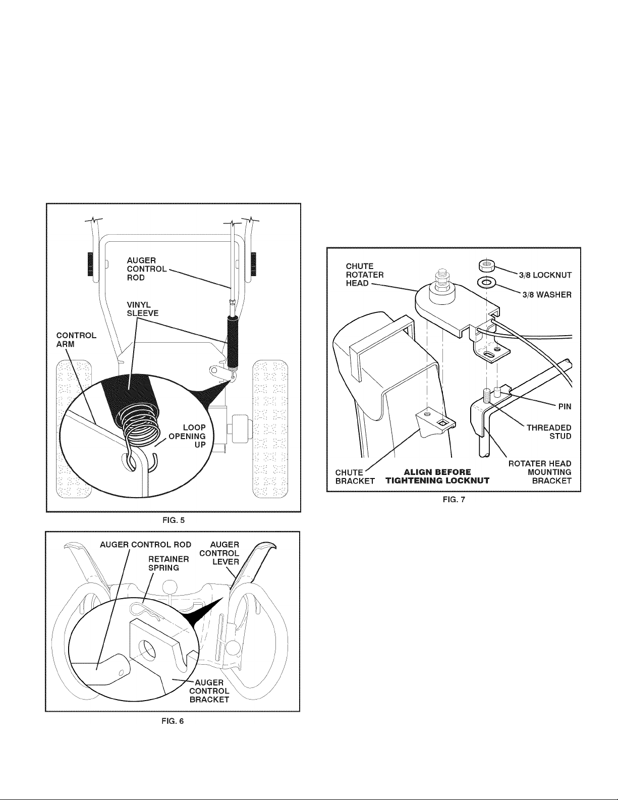
INSTALL AUGER CONTROL ROD (See Figs. 5 and 6)
1, Retrieve vinyl sleeve and spring from bag of parts and
retrieve the auger control rod from carton chute tray.
Slide straight rod end through the small hole in the
vinyl sleeve. Hook spring in hole in rod end,
2, Hook end of spring into control arm with loop opening
up as shown, (See Fig, 5)
3, With top end of rod positioned under right side of
control panel, push down on rod and insert end of rod
into hole in auger control bracket. Secure with retainer
spring.
INSTALL DISCHARGE CHUTE / CHUTE ROTATER
HEAD (See Fig. 7)
NOTE: The multi-wrench provided in your parts bag may
be used to install the chute rotater head,
1, Place discharge chute assembly on top of chute base
with discharge opening toward front of snow thrower,
2, Position chute rotater head over chute bracket. If neces
sary, rotate chute assembly to align square andpin on un
derside of chute rotater headwith holes in chute bracket,
3, With chute rotater head and chute bracket aligned,
position chute rotater head on pin and threaded stud
of mounting bracket,
4, Install 3/8 washer and locknut on threaded stud and
tighten securely.
Page 8

ASSEMBLY / PRE-OPERATION
INSTALL CHUTE DEFLECTOR REMOTE CONTROL
(See Figs. 8 and 9)
1, Install remote cable bracket to discharge chute with
5/16-18 carriage bolt and 5/16-18 locknut as shown.
Tighten securely,
2, Install remote cable eyelet to chute deflector with
1/4-20 shoulder bolt and 1/4-20 locknut as shown.
Tighten nut securely. Eyelet will be loose on shoulder
bolt,
3, Install spring hooks between hex nuts on chute rotater
head and into hole in chute deflector as shown.
CHECK TIRE PRESSURE
The tires on your snow thrower were overinflated at the fac
tory forshipping purposes, Correct and equal tire pressure
is important for best snow throwing performance,
• Reduce tire pressure to 14-17 PSI,
Page 9
OPERATION
KNOW YOUR SNOW THROWER
READ THIS OWNER'S MANUALAND ALL SAFETY RULES BEFORE OPERATING YOUR SNOWTHROWER. Oompare
the illustrations with your snow thrower to famiiiarize yourseif with the iocation of various controis and adjustments. Save
this manuai for future reference.
These symbols may appear on your snow thrower or In literature supplied with the product. Learn and understand
their meaning.
A
DANGER ENGINE
OR WARNING ON
i
FUEL OIL
s -c
FORWARD REVERSE
ENGINE
OFF
F R
A DANGER
TO AVOID INJURY FROM
ROTATING AUGER-KEEP
m
HANDS, FEET AND
CLOTHING AWAY.
l\l
FAST SLOW
READ AND FOLLOW ALL SAFETY INFORMATION
AND INSTRUCTIONS BEFORE USE OF THIS PRODUCT.
KEEP THESE INSTRUCTIONS FOR FUTURE REFERENCE.
CHOKE PRIMER
ADANGER
BLOCKAGES MUST NOT BE
CLEARED OUT UNTIL THE ENGINE
IS SHUT OFF, AND THE CLEAN
OUT TOOL MUST BE USED.
NEVER USE YOUR HAND TO
CLEAN OUT THE CHUTE.
IGNITION KEY.
INSERT TO START
AND RUN,
PULL OUT TO STOP.
DISENGAGED
ENGAGED
SNOW
DISCHARGE
TRACTION
DRIVE CONTROL
A DANGER
• READ AND FDLLDW DWNER'S MANUAL.
• NEVER ALLOW CHILDREN TO OPERATE
SNOWTHROWERS.
• KEEP ALL SHIELDS AND GUARDS IN
PLACE WHILE OPERATING.
> SHUT OFF ENGINE AND REMAIN BEHIND
HANDLES UNTIL ALL MOVING PARTS HAVE
STOPPED BEFORE UNCLOGGING OR
SERVICING UNIT.
TO AVOID THROWN OBJECT INJURIES
NEVER DIRECT DISCHARGE AT BYSTANDERS.
USE EXTRA CAUTION WHEN OPERATING ON
GRAVEL SURFACES.
Page 10
OPERATION
GASOLINE
FILLER CAP
MUFFLER
CHOKE
CONTROL
PRIMER
SAFETY
IGNITION
KEY
NOTE: ITEMS ABOVE
ARE SHOWN IN
THEIR TYPICAL
LOCATION ON THE
ENGINE. ACTUAL
LOCATION MAY
VARY WITH THE
ENGINE ON YOUR
UNIT.
AUGER
CONTROL
LEVER.
DRIVE CHUTE
DISCHARGE
SPEED CONTROL
CONTROL LEVER
DEFLECTOR
REMOTE
CONTROL
LEVER
TRACTION
DRIVE
CONTROL
LEVER
LH TURN
TRIGGER
LIGHT
HANDLE
KNOB
MUFFLER
TOOLBOX
AUGERS
MEETS A.N.S.I. SAFETY REQUIREMENTS
Our snow throwers conform to the standards of the American National Standards Institute.
Toolbox - used to store spare shear bolts, locknuts and
wrench.
Safety Ignition key - must be inserted for the engine to
start and run. Remove when snow thrower is not in use.
Electric start button - used for starting the engine.
Recoil (auxiliary) starter handle - used for starting the
engine.
LH and RH turn triggers - used to steer the snow thrower.
Drive speed control lever - used to select forward or
reverse motion and speed of snow thrower.
Primer - pumps additional fuel from the carburetor to the
cylinder for use when starting a cold engine.
ON / OFF switch - used to STOP the engine.
Choke control - used for starting a cold engine.
Throttle/engine control - used to select either FAST or
SLOW engine speed and to STOP the engine.
Traction drive control lever - used to engage power-pro
pelled forward or reverse motion of snow thrower.
Auger control lever - used to engage auger motion (throw
snow).
Deflector remote control lever - used to change the
distance the snow is thrown.
Discharge chute control lever - used to change the di
rection the snow is thrown.
Skid plate - used to adjust height of scraper bar from the
ground.
10
SKID PLATE
Page 11
OPERATION
The operation of any snow thrower can result
in foreign objects thrown into the eyes, which
can result in severe eye damage. Always wear
safety glasses or eye shields while operating
your snow thrower or performing any adjust
ments or repairs. We recommend standard safety glasses
or a wide vision safety mask worn over spectacles,
HOW TO USE YOUR SNOW THROWER
Know how to operate all controls before adding fuel or
attempting to start the engine,
STOPPING
TRACTION DRIVE
• Release traction drive control lever to stop the forward
or reverse movement of the snow thrower,
AUGER
• Release the auger control lever to stop throwing snow,
ENGINE
1, Move ON / OFF switch to “OFF” position,
2, Remove (do not turn) safety ignition key to prevent
unauthorized use,
NOTE: Never use choke to stop engine,
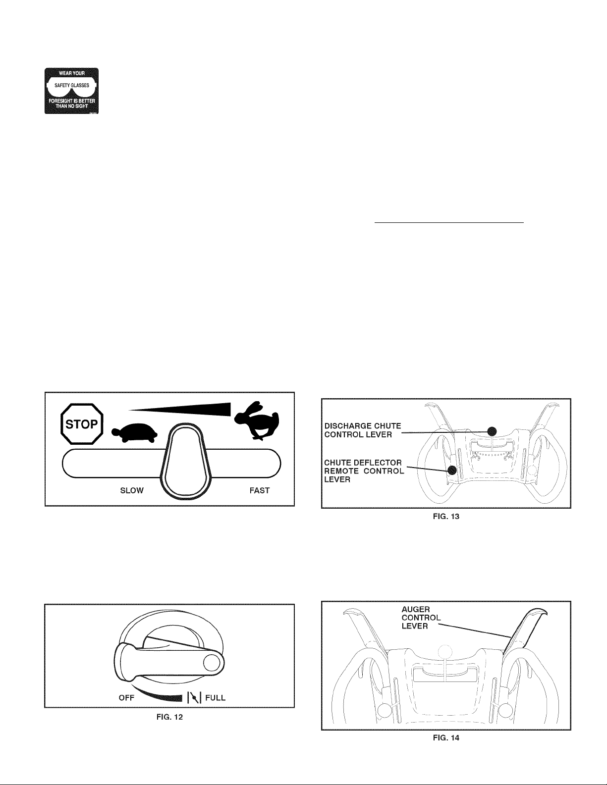
TO USE THROTTLE CONTROL (See Fig. 11)
The throttle control is located on the engine. Always operate
the snow thrower with the engine at full throttle. Full throttle
offers the best snow thrower performance.
TO CONTROL SNOW DISCHARGE (See Fig. 13)
WARNING: Snow throwers have ex
posed rotating parts, which can cause
severe injury from contact, or from ma
terial thrown from the discharge chute.
A
A
The DIRECTION in which snow is to bethrown is controiied
by the discharge chute controi iever,
• To change the discharge chute position, press down
ward on discharge chute controi iever and move iever
ieft or right untii chute is in desired position. Be sure
iever springs back and iocks into desired position.
The DISTANCE that snow is thrown is controiied by the
position of the chute defiector. Set the defiector iow to
throw snow a short distance; set the defiector higher to
throw snow farther,
• Press downward on chute defiector controi iever and
move ieverforward to iowerthe defiector and decrease
the distance. Move iever back to raise the defiector
and increase the distance. Be sure iever springs back
and iocks into desired position.
Keep the area of operation clear of all
persons, small children and pets at all
times Including startup.
WARNING: If the discharge chute or
auger become clogged, shut-off engine
and wait for all moving parts to stop. Use
the clean-out tool, NOT YOUR HANDS,
to unclog the chute and/or auger.
FIG. 11
TO USE CHOKE CONTROL (See Fig. 12)
The choke control is located on the engine. Use the choke
control whenever you are starting a cold engine. Do not
use to start a warm engine,
• To engage choke, turn knob clockwise. Slowly turn
knob counterclockwise to disengage.
TO THROW SNOW (See Fig. 14)
The auger rotation is controiied by the auger controi iever
iocated on the right side handle,
• Squeeze auger control lever to handle to engage the
auger and throw snow.
Release the auger control lever to stop throwing snow.
11
Page 12
OPERATION
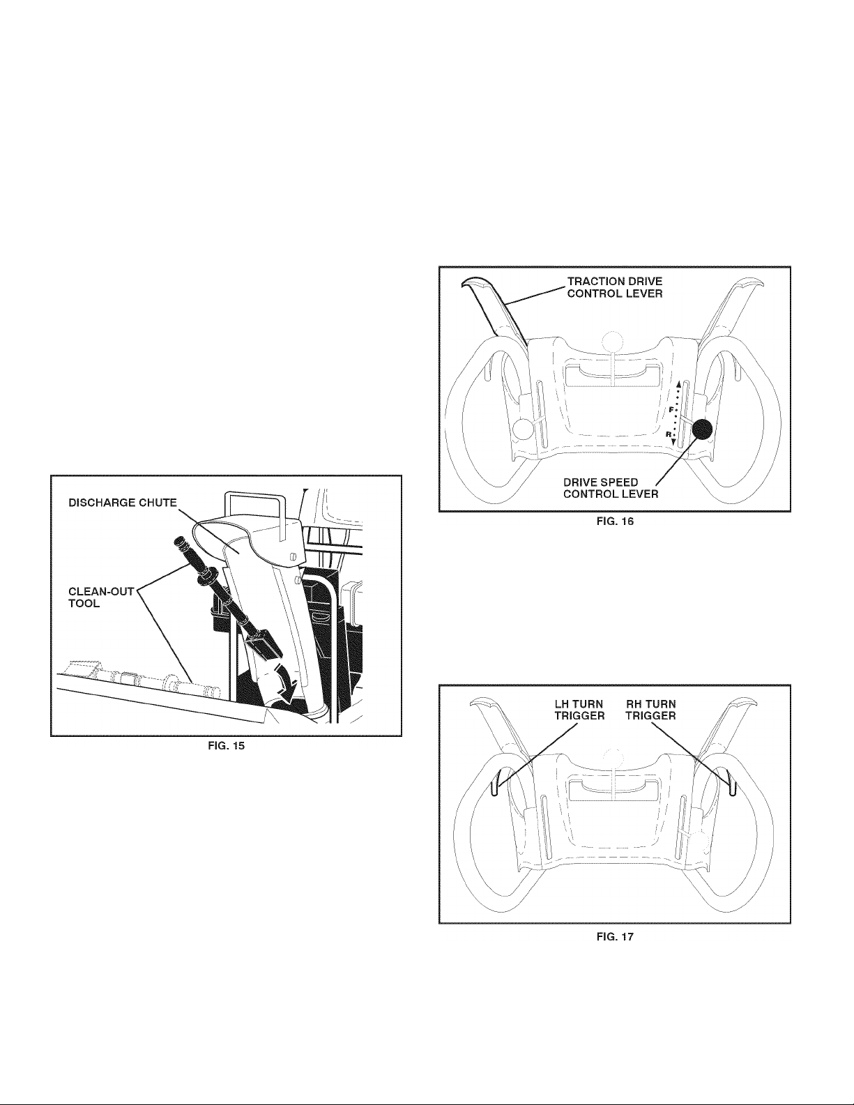
USING THE CLEAN-OUT TOOL (See Fig. 15)
In certain snow conditions, the discharge chute may be
come ciogged with ice and snow. Use the ciean-out tooi
to disiodge this biockage.
When cleaning, repairing, or Inspecting, make
certain all controls are disengaged and the auger/lmpellerandall moving parts have stopped.
Disconnect the spark plug wire and keep the
wire away from the spark plug to prevent ac
cidental starting.
• Release the auger control lever and shut off the engine,
• Remove the clean-outtool from it's mounting clip. Grasp
the tool firmly by the handle and push and twist the tool
into the discharge chute to dislodge the blockage.
After the packed snow has been dislodged, return the clean
out tool to it's mounting clip by pushing it into the clip,
• Make sure the discharge chute is pointed in a safe direc
tion (no vehicles, buildings, people, or other objects are
in the direction ofdischarge) before restarting the engine,
• Restart the engine, then squeeze the auger control
lever to the handle to clear snow from the auger hous
ing and the discharge chute.
• Slower speeds are for heavier snow and faster speeds
are for light snow and transporting the snow thrower. It
is recommended that you use a slower speed until you
are familiar with the operation of the snow thrower,
NOTE: When both traction drive and auger control levers
are engaged, the traction drive control lever will lock the
auger control lever in the engaged position. This will allow
you to release your right hand from the handle and adjust
the discharge chute direction without interrupting the snow
throwing process.
TO MOVE FORWARD AND BACKWARD (See Fig. 16)
SELF-PROPELLING, forward and reverse movement of
the snow thrower, is controlled by the traction drive control
lever located on the left side handle,
• Squeeze traction drive control I ever to handle to engage
the drive system,
• Release traction drive control lever to stop the forward
or reverse movement of the snow thrower,
SPEED and DIRECTION are controlled by the drive speed
control lever,
• Press downward on the speed control lever and move
lever to desired position BEFORE engaging the trac
tion drive control lever. Be sure lever springs back and
locks into desired position,
POWER STEERING OPERATION (See Fig. 17)
Steering triggers are used to assist in steering your
snow thrower. The triggers are located on the underside
of each handle. When a trigger is squeezed, it disen
gages the drive wheel on that side of snow thrower and
allows it to turn in that direction,
• To turn left - squeeze left side trigger,
• To turn right - squeeze right side trigger.
CAUTION: Do not move speed control lever
when traction drive control lever Is engaged.
Damage to the snow thrower can result.
12
Page 13
OPERATION
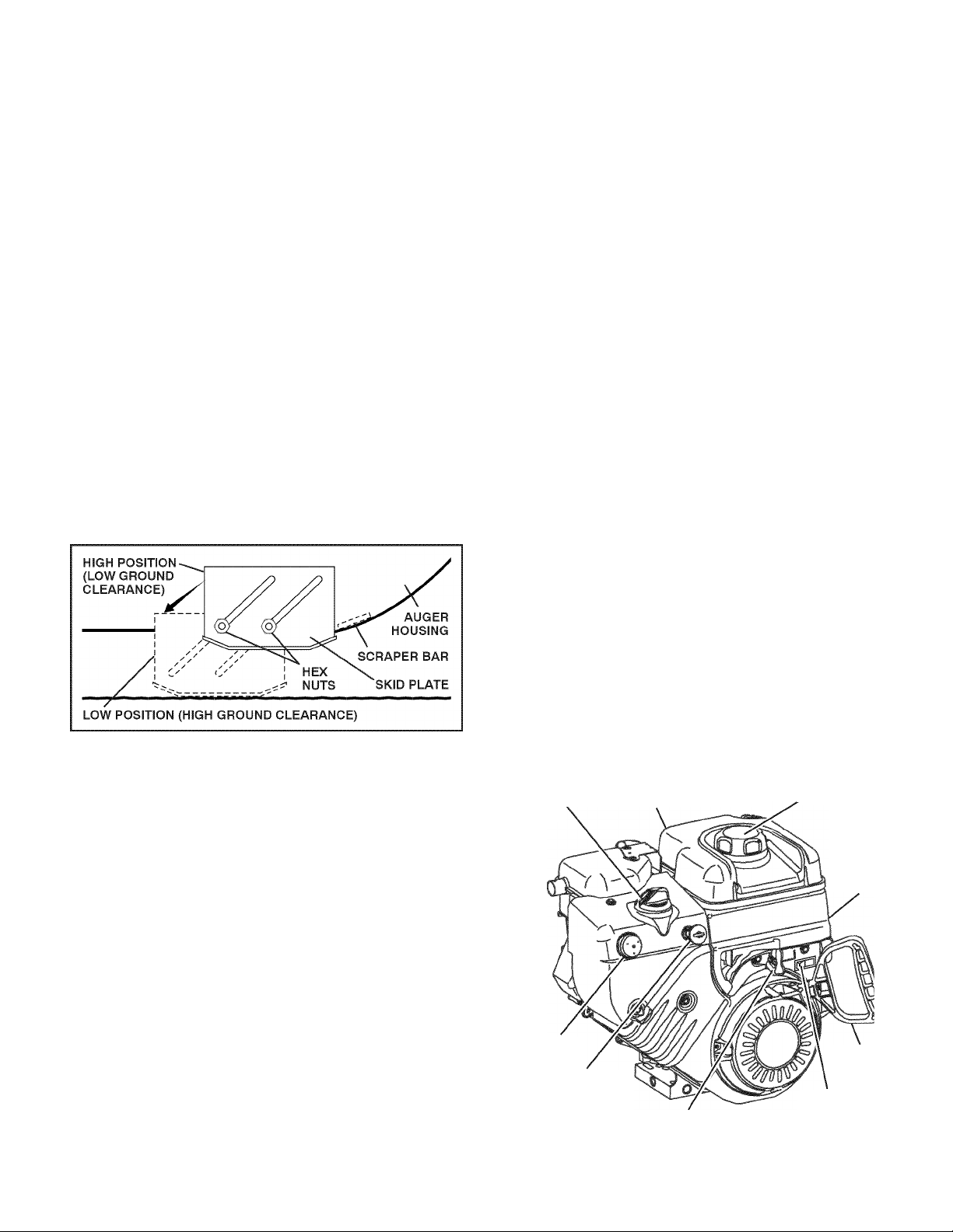
TO ADJUST SKID PLATES (See Fig. 18)
NOTE: The wrench provided in your parts bag may be
used to adjust the skid piates.
Skid piates are iocated on each side of the auger housing
and adjust the ciearance between the scraper bar and the
ground surface. Adjust skid piates eveniy to proper height
for current surface conditions. For removai of snow in
normai conditions, such as a paved driveway or sidewaik,
piace skid piates in the highest position (iowest scraper
ciearance) to give a 1/8" ciearance between the scraper
bar and the ground. Use a middle position if the surface
to be cleared is uneven,
NOTE: It is not recommended to operate the snow thrower
over gravel or rocky surfaces. Objects such as gravel, rocks
or other debris, can easily be picked up and thrown by the
impeller, which can cause serious personal injury, property
damage or damage to the snow thrower,
• If snow thrower must be operated over gravel surface,
use extra caution and be sure skid plates are adjusted
to lowest (highest scraper clearance) position,
1, Shut off engine and wait for all moving parts to stop,
2, Adjust skid plates by loosening the hex nuts, then mov
ing skid plate to desired position. Be sure both plates
are adjusted evenly. Tighten securely.
FIG. 18
SCRAPER BAR (See Fig. 18)
The scraper bar is not adjustable, but is reversible. After
considerable use it may become worn. When it has worn
almost to the edge of the housing, it can be reversed,
providing additional service before requiring replacement.
Replace a damaged or worn scraper bar.
BEFORE STARTING THE ENGINE
CHECK ENGINE OIL LEVEL (See Fig. 19)
The engine on your snow thrower has been shipped, from
the factory, already filled with oil,
1, Check engine oil with snow thrower on level ground,
2, Remove oil fill cap/dipstick and wipe clean, reinsert
the dipstick and screw tight, wait for a few seconds,
remove and read oil level. If necessary, add oil until
“FULL’ mark on dipstick is reached. Do not overfill,
• To change engine oil, see “TO CHANGE ENGINE OIL’
in the Maintenance section of this manual,
ADD GASOLINE (See Fig. 19)
• Fill fuel tank to bottom of tank filler neck. Do not over
fill, Use fresh, clean, regular unleaded gasoline with
a minimum of 87 octane. Do not mix oil with gasoline.
Purchase fuel in quantities that can be used within 30
days to assure fuel freshness.
WARNING: Wipe off any spilled oil or
fuel. Do not store, spill or use gasoline
A
CAUTION: Alcohol blended fuels (called gasohol
or using ethanol or methanol) can attract mois
ture which leads to separation and formation of
acids during storage. Acidic gas can damage
the fuel system of an engine while In storage. To
avoid engine problems, the fuel system should
be emptied before storage of 30 days or longer.
Drain the gas tank, start the engine and let It run
untllthefuel lines and carburetor are empty. Use
fresh fuel next season. See Storage Instructions
for additional Information. Never use engine or
carburetor cleaner products In the fuel tank or
permanent damage may occur.
CHOKE
CONTROL
near an open flame.
ENGINE OIL
FILL CAP / DIPSTICK
GASOLINE
FILLER CAP
STARTER
BUTTON
PRIMER
SAFETY
IGNITION
KEY
NOTE: ALL ITEMS ARE SHOWN IN THEIR TYPICAL LOCATION.
ACTUAL LOCATION MAY VARY WITH ENGINE ON YOUR UNIT.
13
THROTTLE
FIG. 19
ON / OFF
SWITCH
RECOIL
STARTER
HANDLE
Page 14

OPERATION
TO START ENGINE
Your snow thrower engine is equipped with both a 120 Voit
A.C, eiectric starter and a recoii starter. The eiectric starter
is equipped with a three-wire power cord and piug and is
designed to operate on 120 Voit A.C, househoid current,
• Be sure your house is a 120 Voit A.C, three-wire
grounded system. If you are uncertain, consuit a
iicensed eiectrician.
WARNING: Do not use the electric
starter if your house Is not a 120 Volt
A.C. three-wire grounded system. Seri
A
COLD START - ELECTRIC STARTER
1, Insert safety ignition key (tied to recoil start cord) into
ignition siot untii it ciicks, DO NOT turn the key. Keep
the extra safety ignition key in a safe piace,
2, Piace throttie controi in “FAST” position,
3, Piace ON / OFF switch in “ON” position,
4, Rotate choke controi to “FULL position,
5, Connect the power cord to the engine,
6, Piug the other end of the power cord into a three-hoie
grounded 120 Voit A.C, receptacie,
NOTE: Do not use primer when starting engine with the
eiectric starter,
7, Push starter button untii engine starts,
IMPORTANT: Do not crank engine more than five continu
ous seconds between each time you try to start. Wait 5 to
10 seconds between each attempt,
8, When the engine starts, reiease the starter button and
siowiy move the choke controi to the “OFF” position,
9, Disconnect the power cord from the receptacie first,
then from the engine,
Aiiow the engine to warm up for a few minutes. Engine wiii
not deveiop fuii power untii it has reached normai operat
ing temperature,
WARM START - ELECTRIC STARTER
Follow the steps above, keeping the choke controi in the
“OFF” position,
COLD START - RECOIL STARTER
1, Insert safety ignition key (tied to recoii start cord) into
ignition siot untii it ciicks, DO NOT turn the key. Keep
the extra safety ignition key in a safe piace,
2, Piace throttie controi in “FAST” position,
3, Piace ON / OFF switch in “ON” position,
4, Rotate choke controi to “FULL position,
5, Push the primer four (4) times if the temperature is
beiow 15°F or two (2) times if temperature is between
15° and 50°F, If temperature is above 50°F, priming is
not necessary,
NOTE: Over priming may cause flooding, preventing the
engine from starting. If you do flood the engine, wait a few
minutes before attempting to start and DO NOT push the
primer.
ous personal injury or damage to your
snow thrower could result.
6, Puii recoil starter handle quickly. Do not allow starter
rope to snap back,
7, When the enginestarts, release the recoil starter handle
and slowly move the choke control to the “OFF” posi
tion,
Aiiow the engine to warm up for a few minutes. Engine wiii
not deveiop fuii power untii it has reached normai operat
ing temperature,
WARM START - RECOIL STARTER
Follow the steps above, keeping the choke in the “OFF”
position, DO NOT push the primer,
BEFORE STOPPING
Run the engine for a few minutes to heip dry off any mois
ture on the engine,
IF RECOIL STARTER HAS FROZEN
If the recoil starter has frozen and will not turn the engine,
proceed as foiiows:
1, Grasp the recoii starter handle and slowly pull as much
rope out of the starter as possible,
2, Release the recoil starter handle and let it snap back
against the starter.
If the engine stiii faiis to start, repeat the above steps or
use the eiectric starter,
SNOW THROWING TIPS
Aiways operate the snow thrower with the engine at
fuii throttie, Fuii throttie offers the best performance.
Go siowerin deep, freezing or heavy wet snow. Use the
drive speed controi, NOT the throttie, to adjust speed.
It is easier and more efficient to remove snow imme-
diateiy after it faiis.
The best time to remove snow is the eariy morning. At
this time the snow is usuaiiy dry and has not been ex
posed to the direct sun and warming temperatures,
Siightiy overiap each successive path to ensure aii
snow wiii be removed.
Throw snow downwind whenever possibie.
Adjust the skid piates to proper height for current snow
conditions. See “TO ADJUST SKID PLATES” in this
section of this manuai.
For extremeiy heavy snow, reduce the width of snow
removai by overiapping previous path and moving
siowiy.
Keep engine ciean and ciear of snow during use. This
wiii heip air flow and extend engine iife.
After snow-throwing is compieted, aiiow engine to run for
a few minutes to meit snow and ice off the engine,
Ciean the entire snow thrower thoroughiy after each
use and wipe dry so it is ready for next use.
WARNING: Do not operate snow
thrower if weather conditions Impair
visibility. Throwing snow during a
A
heavy, windy snowstorm can blind
you and be hazardous to the safe
operation of the snow thrower.
14
Page 15
MAINTENANCE
MAINTENANCE SCHEDULE
FILL IN DATES
AS YOU COMPLETE
REGULAR SERVICE
T
Check for Loose Fasteners
R
Clean / Inspect Snow Thrower
O
w
Check / Replace V-Belts
E
Lubrication Chart
R
✓
✓ ✓
✓
✓
✓
✓
Check Engine Oil Level
E
Change Engine Oil
N
G
Inspect Muffler
I
N
Check / Replace Spark Plug
E
Empty Fuel Tank
✓
GENERAL RECOMMENDATIONS
The warranty on this snow thrower does not cover items
that have been subjected to operator abuse or negligence.
To receive full value from the warranty, operator must
maintain snow thrower as instructed in this manual. Some
adjustments will need to be made periodically to properly
maintain your snow thrower. All adjustments in the Service
and Adjustments section of this manual should be checked
at least once each season,
• Once a year, you should replace the spark plug and
check belts for wear, A new spark plug will help your
engine run better and last longer,
• Follow the maintenance schedule in this manual,
NOTE: Use only Original Equipment Manufacturer (OEM)
parts to service this unit. Failure to do so can cause the unit
to malfunction and pose a risk of injury to the operator,
✓
✓
✓
✓
LUBRICATION CHART
® SAE 5W-30 Motor Oil
(2) See “ENGINE
In Maintenance
section
(3) General
Purpose
Grease
BEFORE EACH USE
1, Oheck engine oil level,
2, Oheck for loose fasteners,
3, Oheck controls to be sure they are functioning properly,
LUBRICATION
Keep your snow thrower well lubricated
(See “LUBRIOATION OH ART”),
SNOW THROWER
Always observe the safety rules when performing any
maintenance,
TIRES
• Maintain proper air pressure in both tires (14-17 RS,I,),
• Keep tiresfreeofgasoline and oil, which can harm rubber,
NOTE: To seal tire punctures and prevent flat tires due
to slow leaks, tire sealant may be purchased from your
local parts dealer. Tire sealant also prevents tire dry rot
and corrosion.
@ Auger
grease fittings Engine oil
BELTS
Check belts for deterioration and wear after every 50 hours
of operation and replace if necessary. The belts are not
adjustable. Replace belts if they begin to slip from wear,
(See “TO REMOVE BELT COVER” in the Service and
Adjustments section of this manual).
The belts on your snow thrower are of special construction
and should be replaced by original equipment manufacturer
(OEM) belts availablefrom your nearest dealer. Using other
than OEM belts can cause personal injury or damage to
the snow thrower.
15
Page 16

MAINTENANCE
AUGER GEAR CASE
• The gear case was filled with lubricant to the proper
level at the factory. The only time the lubricant needs
attention is if service has been performed on the gear
case,
• If lubricant is required, use only Ronex ED #1
grease,
TRACTION DRIVE SYSTEM
DO NOT lubricate the drive components inside the snow
thrower. The sprockets, hex shafts, drive disc and friction
wheel require no lubrication. The bearings and bushings
are lifetime lubricated and require no maintenance.
CAUTION: Any lubricating of the above compo
nents can cause contamination of the friction
wheel and damage to the drive system of your
snow thrower.
ENGINE
See engine manual,
LUBRICATION
Use only high quality detergent oil rated with API service
classification SG-SL, Select the oil's SAE viscosity grade
according to your expected operating temperature.
SAE VISCOSITY GRADES
5W30 or 10W30
Synthetic 5W30or10W30
-20 30
-30
TEMPERATURE RANGE ANTICIPATED
NOTE: Although multi-viscosity oils (5W30, 10W30 etc,)
improve starting in cold weather, these multi-viscosity oils
will result in increased oil consumption when used above
32°F, Check your engine oil level more frequently to avoid
possible engine damage from running low on oil.
Change theoil afterevery 25 hours of operation oratleastonce
a year ifthe snow thrower is not used for25 hours in one year.
Check the crankcase oil level before starting the engine and
after each five (5) hours of continuous use. Tighten oil fill
cap / dipstick securely each time you check the oil level,
TO CHANGE ENGINE OIL
Determine temperature range anticipated before next oil
change. All oil must meetAPI service classification SG-SL,
• Be sure snow thrower is on level surface,
• Oil will drain more freely when warm,
• Oatch oil in a suitable container.
-20
BEFORE NEXT OIL CHANGE
-10
32 40
0 10
NOTE: The left side wheel may be removed from snow
thrower for easier access to the oil drain plug and place
ment of a suitable container. The unit tilted, resting on the
frame with the left wheel removed, will help drain any oil
trapped inside the engine, (See “TO REMOVE WHEELS”
in the Service and Adjustments section of this manual),
1, Remove safety ignition key and disconnect spark plug
wire from spark plug. Place wire where it cannot come
in contact with spark plug,
Olean area around drain plug.2,
3,
Remove drain plug and drain oil in a suitable container.
4,
Install drain plug and tighten securely.
5,
Wipe off any spilled oil from snow thrower and engine.
6,
Install left wheel (if removed for draining oil). Be sure to
install klick pin into proper hole in wheel axle (See “TO
REMOVE WHEELS” in the Service and Adjustments
section of this manual),
7, Remove oil fill cap/dipstick. Be careful not to allow dirt
to enter the engine,
8, Refill engine with oil through oil dipstick tube. Pour
slowly. Do not overfill. For approximate capacity see
“PRODUOT SPEOIFIOATIONS” section ofthis manual,
9, Use gauge on oil fill cap/dipstick for checking level.
Be sure dipstick cap is tightened securely for accurate
reading. Keep oil at “FULL’ line on dipstick,
10, Wipe off any spilled oil,
MUFFLER
Inspect and replace corroded muffler as it could create a
fire hazard and/or damage,
SPARK PLUG
Replace spark plug at the beginning of each season or after
every 100 hours of operation, whichever occurs first. Spark
plug type and gap setting are shown in the “PRODUCT
SPECIFICATIONS” section of this manual,
CLEANING
IMPORTANT: For best performance, keep snow thrower
housing free of any dirt or trash. Clean the outside of your
snow thrower after each use.
WARNING: Remove safety Ignition key
and disconnect spark plug wire from
A
Keep finished surfaces/wheels free of gasoline, oil, etc.
We do not recommend using a garden hose to clean
your snow thrower unless the electrical system, muffler
and carburetor are covered to keep water out. Water
in engine can result in shortened engine life.
spark plug. Place wire where It cannot
come In contact with spark plug.
16
Page 17

SERVICE AND ADJUSTMENTS
WARNING: To avoid serious injury, before performing any service or adjustments:
^ 1. Be sure the on/off switch is in the OFF position.
2. Remove safety ignition key.
A
3. Make sure the augers and all moving parts have completely stopped.
4. Disconnect spark plug wire from spark plug and place wire where It cannot come In contact
with plug.
/off switch is in the OFF position.
SNOW THROWER
TO ADJUST SNOW THROWER HEIGHT
See “TO ADJUST SKID PLATES” and “SCRAPER BAR”
in the Operation section of this manuai,
CHUTE DEFLECTOR
The chute deflector, attached to the top of the discharge
chute, is provided to direct discharging snow away from
the operator. If the deflector becomes damaged, it shouid
be repiaced.
WARNING: To avoid serious Injury,
never operate your snow thrower with
A
• To change direction and/or distance snow is discharged,
see “TO CONTROL SNOW DISCHARGE” in the Op
eration section of this manuai,
SHEAR BOLTS (See Fig. 20)
AUGER SHEAR BOLTS
Both right and ieft-hand augers are secured to the auger
shaft with a spacer, shear boit and hex nut, Shouid a foreign
object or ice become iodged in the augers, the shear boits
are designed to break, preventing damage to any other
components. If one or both augers do not turn when auger
control lever is engaged, check to see if one or both of the
boits have sheared. To repiace the shear boits:
1, Disengage aii controis and move throttie controi to
STOP position. Wait for aii moving parts to stop.
2,3,Remove safety ignition key and disconnect spark piug
wire from spark piug, Piace wire where it cannot come
in contact with spark piug,
Aiign hoie in auger hub with hoie in auger shaft and
instaii a new 1/4-20 x 2" shear boit, Instaii 1/4-20
iock nut and tighten secureiy,
CAUTION: Do not substitute. Use only original
equipment shear bolts as supplied with your
snow thrower.
the deflector removed or damaged.
3, Aiign hoies in impeiier hub with hoies in impeiier shaft
and instaii two (2) new 1/4-20x1-5/8" capscrew/shear
boits, Instaii 1/4-20 iocknuts and tighten secureiy,
CAUTION: Do not substitute. Use only original
equipment capscrew/shear bolts as supplied
with your snow thrower.
4, Insert safety ignition key and reconnect spark piug wire
to spark piug.
TO REMOVE BELT COVER (See Fig. 21)
1, Remove the two screws securing beit cover to
frame,
2, Remove beit cover,
• Repiace beit cover by instaiiing cover and screws and
tighten secureiy.
4, Insert safety ignition key and reconnect spark piug wire
to spark piug,
IMPELLER SHEAR BOLTS
The impeller is secured to the impeiier shaft with two (2)
capscrew/shear boits and hex nuts, Shouid aforeign object
or ice become iodged in the impeiier, the capscrews are
designed to break, preventing damage to any other com
ponents, If impeller does not turn when auger control lever
is engaged, check to see if the capscrews have sheared.
To repiace the capscrew/shear boits:
1, Disengage aii controis and move throttie controi to
STOP position. Wait for aii moving parts to stop,
2, Remove safety ignition key and disconnect spark piug
wire from spark piug, Piace wire where it cannot come
in contact with spark piug.
FIG. 21
17
Page 18

SERVICE AND ADJUSTMENTS
TO REPLACE BELTS (See Fig. 22)
The auger and traction drive beits are not adjustabie. If the
beits are damaged or begin to siip from wear, they shouid
be repiaced. It is recommended that the beit(s) be repiaced
by a Sears service center/department,
NOTE: It is recommended that both the auger and traction
drive beit be repiaced at the same time.
The V-beits on your snow thrower are of speciai construction
and shouid be repiaced by originai equipment manufacturer
(OEM) beits avaiiabie from your nearest Sears service
center/department. Using other than OEM beits can cause
personai injury or damage to the snow thrower.
WARNING: Belt replacement requires
separation of the snow thrower. While
separating the auger housing from the
frame assembly, It Is Important that
an assistant stand In the operating
A
FRAME
ASSEMBLY
position and hold the snow thrower
handles. Serious personal Injury and/
or damage to the unit could occur if
the snow thrower should fall during
the belt changing process.
AUGER
HOUSING
HANDLES
8, RELIEVE TENSION ON TRAOTION DRIVE BELT
IDLER and remove traction drive beit from around
puiieys,
HINT: Insert a 3/8" drive ratchet (in the “ON” position) into
the square hoie in idler arm and rotate ratchet clockwise
to reiieve tension,
9, With tension reiieved on idier, instaii new traction drive
beit around puiieys and inside beit keepers,
10, Instaii ciutch rod in swing piate; secure with hairpin,
11, Piace auger beit around and inside the groove ofauger
puiiey oniy,
12, Whiie your assistant siowiy raises handles to rejoin
the auger housing and frame assembiy, puii up on the
auger beit and squeeze sides together above puiiey
so beit is fuiiy seated in groove of puiiey,
13, Move idier arm so it does not hit impeiier puiiey as you
bring snow thrower compieteiy together and check
carefuiiy for proper routing of beits. If auger belt has
become dislodged from the pulley (by catchingthe idler
arm bracket while bringing snow thrower together),
separate the snow thrower and repeat step 12, Beit
must be fuiiy seated in puiiey groove when bringing
the snow thrower together,
14, Instaii the two (2) hex boits and tighten secureiy,
15, INSTALL ENGINE PULLEY-Piace beit in puiiey groove
and siide puiiey on crankshaft, Instaii fiat washer, boit
and tighten secureiy (41 -47 N-m torque). Make sure
beit is inside beit keeper,
16, INSTALL BELT OOVER and two (2) screws. Tighten
secureiy,
17, INSTALL DISOHARGE GHUTE - See “INSTALL DIS-
GHARGE GHUTE / GHUTE ROTATER HEAD” in the
Assembiy / Pre-Operation section of this manuai.
1, REMOVE GASOLINE FROM FUEL TANK - Drain
gasoiine from fuei tank into a suitabie container, out
doors, away from fire or flame. Wipe up any spiiied
gasoiine,
2, REMOVE DISOHARGE GHUTE - Loosen iocknut
securing chute rotator head to mounting bracket oniy
enough to aiiow chute rotator head to be raised and
discharge chute to be removed from snow thrower,
3, REMOVE BELT OOVER - See “TO REMOVE BELT
OOVER” in this section of this manuai,
4, REMOVE ENGINE PULLEY-Remove bolt, flat washer
securing puiiey to engine crankshaft. Remove outside
(auger) puiiey oniy from crankshaft,
5, SEPARATE SNOW THROWER - With your assistant
standing in the operating position hoiding the handles,
remove the two (2) bolts holding the auger housing
and frame together.
WARNING: As the last bolt Is removed,
A
6. REMOVE HAIRPIN FROM OLUTOH ROD and re
move clutch rod from swing piate. Tip swing pi ate
forward,
7, REMOVE AUGER BELT from around puiiey.
have your assistant carefully lower the
handles down to the ground.
Page 19

SERVICE AND ADJUSTMENTS
TO REMOVE WHEELS (See Fig. 23)
• Remove the klik pin and remove wheel from axle,
IMPORTANT: When installing wheel, be sure to use the
axle hole closest to the end of the shaft - do not use the
hole in the wheel hub (if equipped). Inner hole in axle and
hole in wheel hub are not used for your model snow thrower,
NOTE: To seal punctures or prevent flat tires due to slow
leaks, tire sealant may be purchased from your local parts
dealer. Tire sealant also prevents tire dry rot and corrosion.
KLIK PIN (INSTALL
IN OUTER HOLE
OF AXLE ONLY)
WHEEL
FIG. 23
HOLE
AXLE
WHEEL HUB
ENGINE
See engine manual,
CARBURETOR
Your carburetor is not adjustable. Engine performance
should not be affected at altitudes up to 7,000 feet (2,134
meters). If your engine does not operate properly due to
suspected carburetor problems, take your snow thrower
to a Sears or other qualified service center,
ENGINE SPEED
Never tamper with the engine governor, which is factory set
for proper engine speed. Overspeeding the engine above
the factory high speed setting can be dangerous and will
void the warranty. If you think the engine-governed high
speed needs adjusting, contact a Sears or other qualified
service center, which has proper equipment and experience
to make any necessary adjustments.
TO ADJUST CABLE TENSION (See Fig. 24)
Adjust cable tension by turning the adjuster turn buckle,
located on the right hand cable. Grasp the long section
tightly and turn the short section to lengthen the adjuster.
Adjust until cable is snug.
19
Page 20

STORAGE
Immediately prepare your unit for storage at the end of the
season or if the unit will not be used for 30 days or more.
WARNING: Never store the snow
thrower with gasoline in the tank Inside
a building where fumes may reach an
open flame, spark or pilot light as on a
A
furnace, water heater, clothes dryer or
gas appliance. Allowthe engine to cool
before storing In any enclosure.
SNOW THROWER
When snow thrower is to be stored for a period of time,
clean it thoroughly, remove all dirt, grease, leaves, etc.
Store in a clean, dry area,
1, Clean entire snow thrower (See “CLEANING” in the
Maintenance section of this manual),
2, Inspect and replace belts, if necessary (See “TO RE
PLACE BELTS” in the Service and Adjustments section
of this manual),
3, Lubricate as shown in the Maintenance section of this
manual,
4, Be sure that all nuts, bolts, screws, and pins are securely
fastened. Inspect moving parts for damage, breakage
and wear. Replace if necessary,
5, Touch up all rusted or chipped paint surfaces; sand
lightly before painting,
ENGINE
See engine manual.
FUEL SYSTEM
IMPORTANT: It is important to prevent gum deposits from
forming in essential fuel system parts such as carburetor,
fuel hose, or tank during storage. Also, alcohol blended
fuels (called gasohol or using ethanol or methanol) can
attract moisture which leads to separation and formation
of acids during storage. Acidic gas can damage the fuel
system of an engine while in storage,
• Empty the fuel tank by starting the engine and letting
it run until the fuel lines and carburetor are empty,
• Never use engine or carburetor cleaner products in
the fuel tank or permanent damage may occur,
• Use fresh fuel next season,
NOTE: Fuel stabilizer is an acceptable alternative in min
imizing the formation of fuel gum deposits during storage.
Add stabilizer to gasoline in fuel tank or storage container.
Always follow the mix ratio found on stabilizer container.
Run engine at least 10 minutes after adding stabilizer to
allow the stabilizer to reach the carburetor. Do not drain the
gas tank and carburetor if using fuel stabilizer,
ENGINE OIL
Drain oil (with engine warm) and replace with clean engine
oil, (See “ENGINE” in the Maintenance section of this
manual),
CYLINDER
1, Remove spark plug,
2, Pour one ounce (29 ml) of oil through spark plug hole
into cylinder,
3, Pull recoil starter handle slowly a few times to distribute
oil,
4, Replace with new spark plug,
OTHER
• Remove safety ignition key; store it in a safe place,
• Do not store gasoline from one season to another,
• Replace your gasoline can if your can starts to rust.
Rust and/or dirt in your gasoline will cause problems,
• If possible, store your snow thrower indoors and cover
it to protect it from dust and dirt,
• Cover your snow thrower with a suitable protective
cover that does not retain moisture. Do not use plastic.
Plastic cannot breathe, which allows condensation to
form and will cause your snow thrower to rust,
IMPORTANT: Never cover snow thrower while engine/exhaust area is still warm.
20
Page 21

TROUBLESHOOTING
See appropriate section in manuai unless directed to a Sears service center/department.
PROBLEM CAUSE CORRECTION
Does not start 1. Fuel shut-off valve (If so
equipped) In OFF position.
2. Safety Ignition key
Is not Inserted.
3. Out of fuel. 3. Fill fuel tank with fresh, clean gasoline.
4. Throttle In STOP position
(or ON/OFF switch Is OFF).
5. Ohoke In OFF position. 5. Move to FULL position.
6. Primer not depressed. 6. Prime as Instructed In the Operation section of this manual.
7. Engine Is flooded. 7. Walt a few minutes before restarting, DO NOT prime.
8. Spark plug wire Is
disconnected.
9. Bad spark plug. 9. Replace spark plug.
10. Stale fuel. 10. Empty fuel tank & carburetor, refill with fresh, clean gasoline.
11. Water In fuel. 11. Empty fuel tank & carburetor, refill with fresh, clean gasoline.
Loss of power 1. Spark plug wire loose. 1. Reconnect spark plug wire.
2. Throwing too much snow. 2. Reduce speed and width of swath.
3. Fuel tank cap Is covered
with Ice or snow.
4. Dirty or clogged muffler. 4. Olean or replace muffler.
1. Turn fuel shut-off valve to OPEN position.
2. Insert safety Ignition key.
4. Move throttle to FAST position
(or ON/OFF switch to ON position).
8. Oonnect wire to spark plug.
3. Remove Ice and snow on and around fuel tank cap.
Engine idies or 1. Ohoke Is In FULL position. 1. Move choke to OFF position.
runs roughiy 2. Blockage In fuel line. 2. Olean fuel line.
3. Stale fuel. 3. Empty fuel tank & carburetor, refill with fresh, clean gasoline.
4. Water In fuel. 4. Empty fuel tank & carburetor, refill with fresh, clean gasoline.
5. Oarburetor Is In need of
5. Oontact a Sears service center/department.
adjustment or overhaul.
Excessive
vibration
Recoii starter
is hard to pull
Loss of traction 1. Drive belt Is worn. 1. Oheck / replace drive belt.
drive / siowing 2. Drive belt Is off of pulley. 2. Oheck / reinstall drive belt.
of drive speed 3. Friction drive wheel Is worn. 3. Oontact a Sears service center/department.
Loss of snow 1. Auger belt Is off of pulley. 1. Oheck / reinstall auger belt.
discharge or 2. Auger belt Is worn. 2. Oheck / replace auger belt.
siowing of 3. Ologged discharge chute. 3. Olean snow chute.
snow discharge 4. Augers / Impeller jammed. 4. Remove debris or foreign object from augers / Impeller.
1. Loose parts or damaged
augers or Impeller.
1. Tighten all fasteners. Replace damaged parts. If vibration
remains, contact a Sears service center/department.
1. Frozen recoil starter. 1. See “IF REOOIL STARTER HAS FROZEN”
In the Operation section of this manual.
21
Page 22

REPAIR PARTS SNOW THROWER - - MODEL NUMBER 944.528398
AUGER HOUSING / IMPELLER ASSEMBLY
NOTE: All component dimensions given In U.S, Inches, 1 Inch = 25,4 mm
IMPORTANT: Use only Original Equipment Manufacturer (0,E,M,) replacement parts.
Failure to do so could be hazardous, damage your snow thrower and void your warranty,
22
Page 23

REPAIR PARTS SNOW THROWER - - MODEL NUMBER 944.528398
AUGER HOUSING / IMPELLER ASSEMBLY
KEY PART
NO. NO. DESCRIPTION
1 175321X479 IMPELLER
2 427148 GEARBOX ASSEMBLY
3 188909 BEARING
4 427146 IMPELLER PULLEY
5 175322 DISCHARGE BASE
6 178675X008 CORNER BRACKET
7 192199 CLEAN OUT TOOL
8 405400 TOOL CLIP
9 73800400 NUT 1/4-20
10 74780426 SCREW 1/4-20 X .625
11 427942 NUT 5/16-18
12 163183 SCREW 5/16-18 X .625
13 427145 IMPELLER HUB
14 427154 IMPELLER SLEEVE
15 73900600 NUT 3/8-16
16 180355 CARRIAGE BOLT
17 194189 SCREW 13-16 X.625
18 407760 PLUG
19 427302 GEARBOX COVER RH
20 427345 GASKET
21 407770 SEAL
22 407762 BEARING
23 174697 THRUST WASHER 1.00
24 407763 WORM GEAR
25 407764 AUGER SHAFT
26 189282 SOUARE KEY
27 407758 BEARING
28 174683 THRUST WASHER
29 427147 IMPELLER SHAFT
30 7836M ROLL PIN
31 174681 THRUST WASHER
32 174684 THRUST BEARING
33 407769 BEARING
34 407768 0-RING
35 407767 SCREW 5/16-18 X .750
36 427317 GEARBOX COVER LH
37 192090 SHEAR BOLT
NOTE: All component dimensions given In U.S, Inches, 1 Inch = 25,4 mm
IMPORTANT: Use only Original Equipment Manufacturer (0,E,M,) replacement parts.
Failure to do so could be hazardous, damage your snow thrower and void your warranty,
23
Page 24

REPAIR PARTS SNOW THROWER - - MODEL NUMBER 944.528398
AUGER HOUSING / IMPELLER ASSEMBLY
KEY PART
NO. NO. DESCRIPTION
1 404929X615 AUGER HOUSING 27
2 404932X428 SCRAPER BAR
3 72270505 CARRIAGE BOLT 5/16-18 X .625
4 155377 NUT 5/16-18
KEY PART
NO. NO. DESCRIPTION
1 420495X479 AUGER 27 LH
2 420496X479 AUGER 27 RH
01.07.018-A
NOTE: All component dimensions given In U.S, Inches, 1 Inch = 25,4 mm
IMPORTANT: Use only Original Equipment Manufacturer (0,E,M,) replacement parts.
Failure to do so could be hazardous, damage your snow thrower and void your warranty,
24
Page 25

REPAIR PARTS SNOW THROWER - - MODEL NUMBER 944.528398
AUGER HOUSING / IMPELLER ASSEMBLY
KEY PART
NO. NO. DESCRIPTION
1 174762X479 SKID PLATE LH
2 178777X479 SKID PLATE RH
3 72270506 CARRIAGE BOLT 5/16-18 X .75
4 751153 NUT 5/16-18
KEY PART
NO. NO. DESCRIPTION
01.07.024-B
NOTE: All component dimensions given in U.S, inches, 1 inch = 25,4 mm
IMPORTANT: Use oniy Originai Equipment Manufacturer (0,E,M,) repiacement parts,
Faiiure to do so couid be hazardous, damage your snow thrower and void your warranty,
1 420478 AUGER BEARING
2 411939 BEARING PLUG
3 179582 SCREW 5/16-18 X 1.00
25
Page 26

REPAIR PARTS SNOW THROWER - - MODEL NUMBER 944.528398
CONTROL PANEL / DISCHARGE CHUTE
KEY PART
NO. NO. DESCRIPTION
1 420315X615 CHUTE WELDMENT
2 178633X615 DEFLECTOR WELDMENT
3 420673 DEFLECTOR CONTROL ASSEMBLY
4 420325 DEFLECTOR SEAL
5 414280 KNOB BLACK
6 128415 POP RIVET
7 17501010 SCREW 10-24 X .625
*8 179829 SHOULDER SCREW
*9 191730 NUT 1/4-20
*10 72250505 CARRIAGE BOLT 5/16-18 X .50
*11 751153 NUT 5/16-18
*12 184505 DEFLECTOR SPRING
13 420679 (SERVICE PART) DEFLECTOR CON'
14 420672 (SERVICE PART) DEFLECTOR CON'
*9
01,09,002-D
NOTE:
1. ALL ITEMS INDICATED WITH AN * ARE PROVIDED IN THE BAG OF ITEMS SHIPPED LOOSE WITH PRODUCT.
2. ITEMS 13 AND 14ARE SERVICE PART NUMBERS TO ALLOW PURCHASE OF INDIVIDUAL ITEMS IF NECESSARY.
NOTE: All component dimensions given in U.S. inches. 1 inch = 25.4 mm
IMPORTANT: Use oniy Originai Equipment Manufacturer (O.E.M.) repiacement parts.
Faiiure to do so couid be hazardous, damage your snow thrower and void your warranty.
26
Page 27

REPAIR PARTS SNOW THROWER - - MODEL NUMBER 944.528398
CONTROL PANEL / DISCHARGE CHUTE
KEY PART
NO. NO. DESCRIPTION
1 428272 LEVER/CABLE ROTATOR ASSEMBLY
2 17501010 SCREW 10-24 X .625
*3 420678 ROTATOR HEAD
*4 405932 ROTATOR PIVOT BRACKET
*5 420675 PULLEY PIVOT
*6 428273 CABLE ASSEMBLY ADJUSTABLE
*7 428310 CABLE ASSEMBLY HEAT SHIELD
NOTES:
1. ITEMS INDICATED WITH AN* ARE LISTED AS REFERENCE FOR SERVICE PARTS ONLY.
KEY
NO.
1 429624 PANEL CONSOLE
2 178668 HEADLIGHT BEZEL
3 178666 HALOGEN HEADLIGHT
4 184471 SHOULDER SCREW
5 175262 SCREW 10-24 X 1.25
6 180964 WIRE HARNESS
7 401620 BULB
PART
NO. DESCRIPTION
01.09.010-B
NOTE: All component dimensions given in U.S, inches, 1 inch = 25,4 mm
IMPORTANT: Use oniy Originai Equipment Manufacturer (O.E.M.) repiacement parts,
Faiiure to do so couid be hazardous, damage your snow thrower and void your warranty,
27
Page 28

REPAIR PARTS
HANDLES
SNOW THROWER - - MODEL NUMBER 944.528398
KEY PART
NO.
1
2
3
4
NO.
419798X479
419799X479
74780524
751153
DESCRIPTION
LOOP HANDLE LH
LOOP HANDLE RH
SOREW 5/16-18 X 1.50
NUT 5/16-18
KEY
NO.
1 412675X004 INTERLOCK SPRING
2 414572 INTERLOCK CAM
3 178831 TORSION SPRING
4 169675 RETAINER
5 17060410 SCREW 1/4-20 X .625
6 421252X004 INTERLOCK STOP
01,08,007-B
NOTE: All component dimensions given In U.S, Inches, 1 Inch = 25,4 mm
IMPORTANT: Use only Original Equipment Manufacturer (O.E.M.) replacement parts.
PART
NO. DESCRIPTION
Failure to do so could be hazardous, damage your snow thrower and void your warranty,
28
Page 29

REPAIR PARTS
HANDLES
SNOW THROWER - - MODEL NUMBER 944.528398
KEY PART
NO. NO. DESCRIPTION
1 412683X479 CONTROL PANEL
2 424517X479 CONTROL LEVERLH
3 424516X479 CONTROL LEVER RH
4 426917X008 TRACTION ROD ARM
5 426918X008 IMPELLER ROD ARM
6 412677 INTERLOCK ROD
7 421613 SPACER
8 169675 RETAINER
9 17060410 SCREW 1/4-20 X .62
10 414280 KNOB BLACK
11 414281 KNOB RED
12 178899 HANDLE KNOB
13 19131316 WASHER 3/8
14 72120618 CARRIAGE BOLT 3/8-16 X 2.25
NOTE: All component dimensions given In U.S, Inches, 1 Inch = 25,4 mm
IMPORTANT: Use only Original Equipment Manufacturer (0,E,M,) replacement parts.
Failure to do so could be hazardous, damage your snow thrower and void your warranty,
29
Page 30

REPAIR PARTS
HANDLES
SNOW THROWER - - MODEL NUMBER 944.528398
KEY PART
NO. NO. DESCRIPTION
1 180480 IMPELLER ROD ASSEMBLY
2 405740 TRACTION ROD ASSEMBLY
3 180445 SHIFTER ROD TOP
4 187716 SHIFTER ROD BOTTOM
5 180447 SPRING SLEEVE
6 178669 IMPELLER SPRING
7 180926 TRACTION SPRING
8 72270505 CARRIAGE BOLT 5/16-18 X .75
9 155377 NUT 5/16-18
10 169675 RETAINER
01.12.001-E
NOTE: All component dimensions given in U.S, inches, 1 inch = 25,4 mm
IMPORTANT: Use oniy Original Equipment Manufacturer (O.E.M.) replacement parts.
Failure to do so could be hazardous, damage your snow thrower and void your warranty,
30
Page 31

REPAIR PARTS
HANDLES
SNOW THROWER - - MODEL NUMBER 944.528398
KEY
NO.
1 419797X479 LOWER TUBE
2 418313X479 PIVOT SUPPORT
3 428867 BOLT 5/16-18 X .750
4 17000616 SOREW 3/8-16 X 1.00
PART
NO. DESCRIPTION
dC®=
01.15.005-A
KEY PART
NO. NO. DESCRIPTION
1 188303 STEER CABLE
2 74041024 SCREW 10-24 X 1.50
NOTE: All component dimensions given In U.S, Inches, 1 Inch = 25,4 mm
IMPORTANT: Use only Original Equipment Manufacturer (0,E,M,) replacement parts.
Failure to do so could be hazardous, damage your snow thrower and void your warranty,
31
Page 32

REPAIR PARTS
DRIVE
SNOW THROWER - - MODEL NUMBER 944.528398
32
01,02,013-A
Page 33

REPAIR PARTS
SNOW THROWER - - MODEL NUMBER 944.528398
DRIVE
KEY PART KEY PART
NO. NO. DESCRIPTION NO. NO. DESCRIPTION
1 198875 SPEED SELECTOR
ASSEMBLY
2 17501010 SCREW 10-24 X .625
3 402685X615 END PLATE
4 17490508 SCREW 5/16-18 X .50
5 57079 WASHER
6 405485 CONTROL ARM
7 198580 CLEVIS PIN
8 403097X004 SHIFTER PLATE
9 402881 SHOULDER BOLT
10 403096X004 SHIFTER BRACKET
11 191730 NUT 1/4-20
12 402856X004 CLUTCH PLATE
13 416717X004 CLUTCH BRACKET
14 187101 SHIFTER LINK
15 700279 RETAINER
16 427542 CONTROL SHAFT
17 402568 CLUTCH ROD
18 169675 RETAINER
19 401732 SHIFTER YOKE
20 402310 PIVOT ROD
21 12000036 RETAINER
22 402878 RETURN SPRING
23 751153 NUT 5/16-18
24 408981 BEARING
25 73930500 NUT 5/16-18
26 198176X479 RUBBER WHEEL PLATE
27 179831 RUBBER RING
28 175344 BEARING
29 178613 WHEEL HUB
30 74760514 SCREW 5/16-18-.875
31 12000012 RETAINER RING
32 402187 SPROCKET SHAFT
33 401619 CHAIN
34 417234 SPROCKET WELDMENT
35 401984X479 SHIFTER BRACKET
36 180135 SPRING
37 402652 PLATE PIVOT ROD
38 428288 E-RING .375
39 184471 SHOULDER SCREW
40 410877 BOTTOM PAN
41 413429X479 SPRING BRACKET
42 402689 DRIVE PLATE ASSEMBLY
43 414557 IDLER SPRING
44 178828 IDLER SPRING
45 402504X008 PULLEY SHAFT
46 401820 DRIVE PLATE
47 198791 BEARING
48 402393 PULLEY HALF
49 17541008 SCREW 10-24 X .50
50 402511 SPACER BEARING
51 418894X479 SWING PLATE
52 132010 NUT 3/8-16
53 428867 SCREW 5/16-18 X .750
NOTE: All component dimensions given In U.S, Inches, 1 Inch = 25,4 mm
IMPORTANT: Use only Original Equipment Manufacturer (0,E,M,) replacement parts.
Failure to do so could be hazardous, damage your snow thrower and void your warranty,
33
Page 34

REPAIR PARTS
DRIVE
SNOW THROWER - - MODEL NUMBER 944.528398
01,03.002-A
KEY PART
NO. NO. DESCRIPTION
1 404923 AXLE ASSEMBLY (Assy of la,1b)
1a 404307 AXLE SHAFT
1b 9465M1 ROLL PIN 3/16X1.50
2 402691 SPROOKET
3 174697 THRUST WASHER
4 179830 BEARING
5 146315 SOREW 5/16-18 X .625
6 17490508 SOREW 5/16-18 X .500
7 155443 KLIKPIN 1/4 X 1.50
8 189282 SOUAREKEY
NOTE: All component dimensions given In U.S, Inches, 1 Inch = 25,4 mm
IMPORTANT: Use only Original Equipment Manufacturer (0,E,M,) replacement parts.
Failure to do so could be hazardous, damage your snow thrower and void your warranty,
34
Page 35

REPAIR PARTS
CHASSIS/PULLEYS
SNOW THROWER - - MODEL NUMBER 944.528398
,"Vv -fii i ''
J
I
II 'X
1-/.^'" ¡-X '•
''-J.
r t'
§ '--oxx;
KEY PART
NO. NO.
----------
B&S ENGINE MODEL
DESCRIPTION
20M114-1358-E2
1
2
3
418694X615 FRAME
150406 BOLT 3/8-16
428867 SOREW 5/16-18 X .750
KEY PART
NO. NO. DESCRIPTION
423185X615 ENGINE MOUNT PLATE
NOTE: All component dimensions given in U.S, inches, 1 inch = 25,4 mm
IMPORTANT: Use oniy Original Equipment Manufacturer (0,E,M,) replacement parts.
Failure to do so could be hazardous, damage your snow thrower and void your warranty,
35
Page 36

REPAIR PARTS
CHASSIS / PULLEYS
SNOW THROWER - - MODEL NUMBER 944.528398
KEY PART
NO. NO. DESCRIPTION
1 428684 COVER ASSEMBLY
NOTE: All component dimensions given In U.S, Inches, 1 Inch = 25,4 mm
IMPORTANT: Use only Original Equipment Manufacturer (0,E,M,) replacement parts.
Failure to do so could be hazardous, damage your snow thrower and void your warranty,
36
Page 37

REPAIR PARTS SNOW THROWER - - MODEL NUMBER 944.528398
CHASSIS/PULLEYS
KEY PART KEY PART
NO. NO. DESCRIPTION NO. NO. DESCRIPTION
1 408007 IMPELLER BELT
2 419744 TRACTION BELT
3 423723X479 IDLER ARM BRACKET
4 180523 IDLER PULLEY
5 426589 NUT 5/16-18
6 74780524 SCREW 5/16-18X1 .50
7 423990X479 IDLER BRACKET
8 428867 SCREW 5/16-18 X .625
9 424297 SHOULDER BOLT 5/16-18 X .500
10 751153 NUT 5/16-18 NYLOCK
11 187786 TRACTION IDLER ARM
12 180522 TRACTION PULLEY
NOTE: All component dimensions given In U.S, Inches, 1 Inch = 25,4 mm
IMPORTANT: Use only Original Equipment Manufacturer (0,E,M,) replacement parts.
Failure to do so could be hazardous, damage your snow thrower and void your warranty,
13 74780520 SCREW 5/16-18 X 1 .00
14 59289 WASHER
15 73800500 NUT 5/16-18
16 851084 SCREW 3/8-24 X 1.375
17 400026 WASHER
18 426491 PULLEY ENG IMPELLER
19 426490 PULLEY ENG TRACTICN
20 74610516 SCREW 5/16-18 X 1 .00
21 10040500 LCCKWASHER5/16
22 155452 BELT GUIDE
23 11050500 LGCKWASHER5/16
24 175331 IDLER BUSHING
37
Page 38

REPAIR PARTS
WHEELS
■j
SNOW THROWER - - MODEL NUMBER 944.528398
-23
^14
-2 01.15.001-A
KEY PART KEY PART
NO. NO. DESCRIPTION NO. NO. DESCRIPTION
1 405161 COVER
2 184471 SHOULDER SCREW
3 12000045 RETAINER RING
4 192126 WHEEL DRIVER
5 182466 RETAINER RING
6 187622 WHEEL LOBE
7 194941 CLUTCH SLIDE
8 179139 SPRING
9 189282 SOUAREKEY
10 194940 AXLE LOBE
11 174697 THRUST WASHER
12 193506X479 STEERING YOKE
13 179148X479 STEERING BRACKET
14 17490508 SCREW 5/16-18 X .50
15 194943X008 PIVOT BRACKET
16 194944X008 BELLCRANK
17 181847 BELLCRANK PIN
18 17600406 SCREW 1/4-20 X .375
19 405077 STEERING LINK
20 700279 RETAINER
21 85179 RETAINER
22 193885 SPRING
23 182015 LEVER PIN
24 194939X008 PIVOT BRACKET
NOTE: All component dimensions given In U.S, Inches, 1 Inch = 25,4 mm
IMPORTANT: Use only Original Equipment Manufacturer (0,E,M,) replacement parts.
Failure to do so could be hazardous, damage your snow thrower and void your warranty,
38
Page 39

REPAIR PARTS
WHEELS
01,06.006-A
SNOW THROWER - - MODEL NUMBER 944.528398
KEY PART
NO. NO. DESCRIPTION
1 196752X417 WHEEL ASSEMBLY LH
2 196753X417 WHEEL ASSEMBLY RH
KEY PART
NO. NO. DESCRIPTION
1 410293 CABLE BRACKETLH
2 410294 CABLE BRACKET RH
3 17060410 SCREW 1/4-20 X .625
NOTE: All component dimensions given In U.S, Inches, 1 Inch = 25,4 mm
IMPORTANT: Use only Original Equipment Manufacturer (0,E,M,) replacement parts.
Failure to do so could be hazardous, damage your snow thrower and void your warranty,
39
Page 40

REPAIR PARTS
BAG OF PARTS
5^
SNOW THROWER - - MODEL NUMBER 944.528398
KEY PART
10
NO. NO.
1
2
3
4
5
6
7
8
9
10
11
12
198563
169675
180684X008
184505
179829
191730
72250505
751153
73800600
19131316
192090
73800400
DESCRIPTION
POWER CORD
RETAINER PIN
WRENCH
REMOTE SPRING
SHOULDER BOLT 1/4-20
LOCKNUT 1/4-20
CARRIAGE BOLT 5/16-18 X 5/8
LOCKNUT 5/16-18
LOCKNUT 3/8-16
WASHER 3/8
SHEAR BOLT 1/4-20 X 1-13/16
LOCKNUT 1/4-20
01.14.007-A
KEY PART
NO. NO.
1 193071
S
.....
.........
DESCRIPTION
SAFETY IGNITION KEY
1 180445 SHIFTER ROD TOP
2 187716 SHIFTER ROD BOTTOM
3 72270505 CARRIAGE BOLT 5/16-18 X .75
4 155377 NUT 5/16-18
NOTE: All component dimensions given in U.S, inches, 1 inch = 25,4 mm
IMPORTANT: Use oniy Original Equipment Manufacturer (O.E.M.) replacement parts.
Failure to do so could be hazardous, damage your snow thrower and void your warranty,
40
Page 41

REPAIR PARTS
DECALS
SNOW THROWER - - MODEL NUMBER 944.528398
KEY PART
NO. NO.
1 181037
3 181035
4 181042
- -
- -
429850
429851
DESCRIPTION
DECAL, DANGER
DECAL, DANGER, DEFLECTOR
DECAL, DANGER
OWNER'S MANUAL, ENGLISH
OWNER'S MANUAL, FRENCH
NOTE: All component dimensions given in U.S, inches, 1 inch = 25,4 mm
IMPORTANT: Use oniy Original Equipment Manufacturer (0,E,M,) replacement parts.
Failure to do so could be hazardous, damage your snow thrower and void your warranty,
41
Page 42

BRIGGS & STRATTON 4-CYCLE ENGINE MODEL NUMBER 20M114-1358-E2
48 SHORT BLOCK
1058 OPERATOR’S MANUAL 1329 REPLACEMENT ENGINE 1330 REPAIR MANUAL
163 a
51
633 ®
42
Page 43

BRIGGS & STRATTON 4-CYCLE ENGINE MODEL NUMBER 20M114-1358-E2
1318 i
1392
326
// 304
- ¿7
608
458
597
Wi
li'jl
456
309
58 ;
p 33^
689
459
592'
281
37 > '>
—-
125
97
633 ®
98
122 I 51A
51
3
%
663
528
X
731A
109
95 «
975
13C
133 104
1127
108
127«.
117'
135
105 (
137
892
190
356
957A
187 1
<1 3:.^^
1119
«e *
474
731
1251
......
1251A
976 AM
1 930!
11
23
I'.'"' ' *l
r
JJ
"«/ 592 #,»
^
^ 65
' %
1005
1070
1070
€3
455
332
43
Page 44

BRIGGS & STRATTON 4-CYCLE ENGINE MODEL NUMBER 20M114-1358-E2
KEY PART KEY PART
NO. NO. DESCRIPTION NO. NO. DESCRIPTION
1 794849 Cylinder Assembly 137 698781 0 Gasket-Float Bowl
2 698340 KIt-BushIng/Seal (Magneto Side) 146 690979 Key-TImIng
3 391086s
5 794871 Head-Cylinder 177 795015 Seal-C Ring (Dipstick)
7 694872 *+ Gasket-Cylinder Head 187 791879 Line-Fuel
11 696750 Tube-Breather 188 699479 Screw (Control Bracket)
12 694953
13 794829 Screw (Cylinder Head) 192 690083 Adjuster-Rocker Arm
15 691686 Plug-011 Drain 209 694867 Spring-Governor (Red)
16 794720 Crankshaft 211 695307 Spring-Governed Idle
18 791965 Cover-Crankcase 219 693578 Gear-Governor
19 698340 KIt-BushIng/Seal (PTC Side) 220 691724 Washer (Governor Gear)
20 391086s
21 281658s Cap-011 Fill 227 694864 Lever-Governor Control
22 794825 Screw (Crankcase Cover/Sump) 278 792008 Washer (Governor Control Lever)
23 794812 Flywheel 281 697268 Panel-Control
24 222698s Key-Flywheel 287 699629 Screw (Dipstick Tube)
25 792117 Piston Assembly (Standard) 300 794948 Muffler
792144 Piston Assembly (,020” Cversize) 304 795699 Housing-Blower
26 793561 Ring Set (Standard) 305 699480 Screw (Blower Housing)
792073 Ring Set (,020” Cversize) 306 697240 Shield-Cylinder
27 690975 Lock-Piston Pin 307 794822 Screw (Cylinder Shield)
28 696581 PIn-PIston 309 795909 Motor-Starter
29 694691 Rod-Connecting 326 690837 Screw (Rewind Guard)
30 694692 Dipper-Connecting Rod 332 794824 Nut (Flywheel)
32 690976 Screw (Connecting Rod) 333 492341 Armature-Magneto
33 499596 Valve-Exhaust 334 699477 Screw (Magneto Armature)
34 795199 Valve-Intake 337 691043 Plug-Spark
35 694865 Spring-Valve (Intake) 356 793206 Wire-Stop
36 694865 Spring-Valve (Exhaust) 358 795201 Gasket Set-Engine
42 499586 Keeper-Valve 404 795759 Washer (Governor Crank)
45 690977 Tappet-Valve 410 695382 Link-Control
46 795697 Camshaft 455 795011 Cup-Flywheel
48 794910 Short Block 456 692299 Plate-Pawl Friction
51 694874*+ 0 Gasket-Intake 458 699334 KIt-Handle/Rope
51A 694875*+ 0 Gasket-Intake 459 281505s Pawl-Ratchet
53 795017 Stud (Carburetor) 472 791948 Knob-Choke Shaft
55 696710 Housing-Rewind Starter 474 793640 Alternator
58 693389 Rope-Starter 485 695755 Knob-Control
65 699851 Screw (Rewind Starter) 504 695383 Washer Set-Frictlon
95 690718 Screw (Throttle Valve) 505 691251 Nut (Governor Control Lever)
97 696387 Shaft-Throttle 523 790477 Dipstick
98 695408 0 KIt-ldle Speed 524 691876 Seal-0 Ring (Dipstick Tube)
104 694918 0 Pin-Float Hinge 525 792041 Tube-DIpstIck
105 696136 0 Valve-Float Needle 528 793006 Hose-Primer
108 696143 Valve-Choke 529 791822 Grommet
109 793520 Shaft-Choke 552 694674 Bushing-Governor Crank
117 796080 0 Jet-Main (Standard) 562 793216 Bolt (Governor Control Lever)
118 796128 0 Jet-Main (High Altitude) 564 699854 Screw (Control Cover)
121 796137 KIt-Carburetor Cverhaul 597 691696 Screw (Pawl Friction Plate)
122 796315 Spacer-Carburetor 601 791850 Clamp-Hose (Green)
125 796122 Carburetor 604 696758 Cover-Control
127 690727 0 Plug-Welch 604A 790473 Cover-Control
130 696139 Valve-Throttle 608 699335 Starter-Rewind
133 694914 Float-Carburetor 610 794541 Arrester-Intake
135 698780 Tube-Fuel Transfer
«
Seal-011 (Magneto Side) 163 692277+ 0 Gasket-Air Cleaner
«
Gasket-Crankcase 190 699220 Screw (Fuel Tank)
«
Seal-011 (PTC Side) 222 794800 Bracket-Control
NOTE: All component dimensions given In U.S, Inches, 1 Inch = 25,4 mm
IMPORTANT: Use only Original Equipment Manufacturer (0,E,M,) replacement parts.
Failure to do so could be hazardous, damage your snow thrower and void your warranty,
44
Page 45

BRIGGS & STRATTON 4-CYCLE ENGINE MODEL NUMBER 20M114-1358-E2
KEY PART KEY PART
NO. NO. DESCRIPTION NO. NO. DESCRIPTION
613 794846 Screw (Muffler) (M6)
613A 794844 Screw (Muffler) (M8) (Torx)
614 691620 Pin-Cotter
616 795758 Crank-Governor
621 692310 Switch-Stop
632 695917 Spring/Link-Mechanical Governor
633 690998 0 Seal-Choke/Throttle Shaft (Throttle
Shaft)
635 691909 Boot-Spark Plug
663 699854 Screw (Control Panel) (M5x10)
668 794539 Spacer (Snow Hood)
668A 694257 Spacer (Control Bracket)
689 691855 Spring-Friction
697 795012 Screw (Starter Motor)
718 690959 Pin-Locating (Cylinder)
718A 695178 Pin-Locating (Cylinder Head)
725 696756 Shield-Heat
727 697465 Cover-Starter Drive
731 794540 Hood-Snow
731A 793621 Hood-Snow
732 699200 Screw (Starter Drive Cover)
741 691288 Gear-Timing
742 692564 Retainer-E Ring
746 694679 Gear-Idler
751 794839 Washer (Stop Wire)
773 694258 Retainer (Control Bracket)
798 697890 Screw (Rocker Cover)
847 795087 Dipstick/Tube Assembly
851 692424 Terminal-Spark Plug
868 794086 *+ Seal-Valve
883 695398 *+ Gasket-Exhaust
892 791944 Switch-Key
914 794827 Screw (Rocker Cover)
930 696709 Guard-Rewind
957 795027 Cap-Fuel
957A 792647 Cap-Fuel (Fuel Fresh)
972 694260 Tank-Fuel
975 698783 Bowl-Float
976 793382 Primer-Carburetor
998 792928 Pipe-Oil
1005 794815 Fan-Flywheel
1022 690971 •+ Gasket-Rocker Cover
1023 698042 Cover-Rocker
1026 695177 Rod-Push
1029 690972 Arm-Rocker
1036 Label-Emissions (Available from
a Briggs & Stratton Authorized
Dealer)
1058 277104 Operator’s Manual
1070 794821 Screw (Flywheel Fan)
1095 795200 Gasket Set-Valve
1100 791959 Pivot-Rocker Arm
1119 699772 Screw (Alternator)
1127 695407 Screw (Float Bowl)
1138 694255 Nut (Control Bracket) (High Speed
Control)
1171 794828 Stud (Rocker Arm Cover)
1196 696692 Screw (Snow Hood)
1210 498144 Pulley/Spring Assembly (Pulley)
1211 498144 Pulley/Spring Assembly (Spring)
1230 699847 Stud (Control Bracket)
1251 696762 Shield-Snow
1251A 790471 Shield-Snow
1252 699480 Screw (Snow Shield)
1288 794838 Nut (Snow Hood)
1318 698111 Knob-Snow Hood
1329 20P414-
0015-E1 Replacement Engine
1351 794847 Stud (Cylinder Shield)
1392 690800 Nut (Rewind Guard)
1427 695757 Cap-Pipe
«
0 Carburetor Cverhaul Kit Key No, 121
+ Valve Gasket Set Key No, 1095
Engine Gasket Set Key No, 358
Engine Power Rating Information
The gross power rating for individual gas engine models is labeled in accordance with SAE (Society of Automotive En
gineers) code J1940 (Small Engine Power & Torque Rating Procedure), and rating performance has been obtained and
corrected in accordance with SAE J1995 (Revision 2002-05), Torque values are derived at 3060 RPM; horsepower values
are derived at 3600 RPM, Actual gross engine power will be lower and is affected by, among other things, ambient operat
ing conditions and engine-to-engine variability. Given both the wide array of products on which engines are placed and
the variety of environmental issues applicable to operating the equipment, the gas engine will not develop the rated gross
power when used in a given piece of power equipment (actual “on-site” or net power). This difference is due to a variety
of factors including, but not limited to, accessories (air cleaner, exhaust, charging, cooling, carburetor, fuel pump, etc,),
application limitations, ambient operating conditions (temperature, humidity, altitude), and engine-to-engine variability.
Due to manufacturing and capacity limitations, Briggs & Stratton may substitute an engine of higher rated power for this
Series engine.
NOTE: All component dimensions given in U,S, inches, 1 inch = 25,4 mm
IMPORTANT: Use only Original Equipment Manufacturer (0,E,M,) replacement parts.
Failure to do so could be hazardous, damage your snow thrower and void your warranty,
45
Page 46

GENERAL: Craftsman products are warranted to be free from defects in materials or workmanship for a specific time period
as set-out below (the “Warranty Period”). Warranties extend to the original purchaser of a Craftsman product only. Purchases
made through an online auction or through any website other than
commences on the original date of purchase. Within this period, SEARS CANADA, Inc. will, at its sole option, repair or replace
any products or components which fail in normal use. Such repairs or replacement will be made at no charge to the customer for
parts or labor, provided that the customer shall be responsible for any transportation cost.
www.sears.ca are excluded. The relevant Warranty Period
EXCLUSIONS: This warranty does not cover failures due to normal wear, abuse, misuse, neglect (including but not limited to
the use of stale fuel, dirt, abrasives, moisture, rust, corrosion, or any adverse reaction due to improper storage or use habits),
improper maintenance or failure to follow maintenance guidelines and/or instructions, failure to operate the product in accordance
with the owner’s manual or any additional instructions or information provided at the time of purchase or in subsequent
communications with the original purchaser, accident or unauthorized alterations or repairs made or attempted by others. Also
excluded from warranty coverage - except as provided below - are the following: maintenance, adjustments, components subject
to wear including but not limited to: cosmetic components, belts, blades, blade adapters, bulbs, tires, filters, guide bars, lubricants,
seats, grips, recoil assy’s, saw chains and bars, trimmer lines and spools, spark plugs, starter ropers and tines, and discoloration
resulting from ultraviolet light. Any product missing the model and/or serial number identification label will be disqualified from
coverage under this warranty.
REPAIRS: Repairs have a 90 day warranty. If the defective product is still within the Warranty Period, then the new warranty is 90
days from the date of repair or to the end of the original Warranty Period, whichever period is longer.
DISCLAIMERS: THE WARRANTIES AND REMEDIES CONTAINED HEREIN ARE EXCLUSIVE AND IN LIEU OF ALL OTHER
WARRANTIES, WHETHER ORAL OR WRITTEN (OTHER THAN AS STATED HEREIN), AND WHETHER EXPRESS, IMPLIED
OR STATUTORY INCLUDING BUT NOT LIMITED TO ANY THIS WARRANTY GIVES YOU SPECIFIC LEGAL RIGHTS, WHICH
MAY VARY FROM PROVINCE TO PROVINCE.
IN NO EVENT SHALL SEARS BE LIABLE FOR ANY INCIDENTAL, SPECIAL, INDIRECT OR CONSEQUENTIAL DAMAGES,
WHETHER RESULTING FROM THE USE, MISUSE OR INABILITY TO USE THE PRODUCT OR FROM DEFECTS IN THE
PRODUCT. THE EXCLUSIONS IN THIS PARAGRAPH SHALL NOT APPLY IN JURISDICATIONS WHERE APPLICABLE LAW
DOES NOT ALLOW FOR THE EXCLUSION OF INCIDENTAL OR CONSEQUENTIAL DAMAGES. IN SUCH JURISDICTIONS,
THIS PARAGRAPH SHALL NOT APPLY BUT THE REMAINING PROVISIONS OF THIS DOCUMENT SHALL REMAIN VALID.
SEARS retains the exclusive right to repair or replace the product or offer a fu
SUCH REMEDY SHALL BE YOUR SOLE AND EXCLUSIVE REMEDY FOR ANY BREACH
_______________
refund of the purchase price at its sole discretion.
...
OF WARRANTY
CUSTOMER RESPONSIBILITIES: In additional to complying with all suggested maintenance guidelines and instructions,
customers’ obligations shall include but shall not be limited to: operating the product in accordance with the owner’s manual or
any additional instructions or information provided at the time of purchase or in subsequent communications to the purchaser from
time to time, exhibit reasonable care in the use, operation, maintenance, general upkeep and storage of the product. Failure to
comply with these requirements will void any applicable warranty.
LIST OF APPLICABLE WARRANTY PERIODS: The following list contains the applicable Warranty Period for your Craftsman product
and is based on a combination of the type of product or component and the intended and actual use of the product or component:
1. 90 DAYS: Craftsman products intended for use or actually used for commercial, institutional, professional or income-
producing purposes
2. 2 YEARS: Craftsman riding lawn mowers, yard and garden tractors, walk behind mowers, tillers, brush cutters,
snow blowers, handheld blowers, backpack blowers, hedge trimmers and electrical products for noncommercial,
nonprofessional, non-institutional, or non-income-producing use, except for those components which are part of engine
systems manufactured by third party engine manufacturers for which the purchase has received an separate warranty
with product information supplied at the time of purchase.
3. 1 YEAR: Craftsman power cutters, stump grinders, pole pruners, gas chain saws, electric chain saws, trimmer
attachments, baggers and pole saws for noncommercial, nonprofessional, non-institutional, or non-income-producing use.
4. 90 DAYS: All defective batteries, which will be replaced during this 90-day Warranty Period.
5. 60 DAYS: Additional Warranty Period of 60 days will apply to adjustments and worn products or components BUT DOES
NOT INCLUDE WEAR OR ADJUSTMENTS for products used for commercial, institutional, professional or incomeproducing purposes. Wear items include but are not limited to: belts, blades, tires, spark plugs, air filters, chains, shear
bolts, skid plates, scraper bars, drift cutters, ropes, tines, collection bags and pulleys.
As the Warranty Period runs from the date of purchase and NOT from the date that a product is delivered, opened, assembled or
first used, please ensure during this time period that your product or component has been assembled and tested for correction
operation regardless of when you intend to actually use it. Claims made after the Warranty Period has expired will not be honored.
PROOF OF PURCHASE/DOCUMENTATION: Warranty coverage is conditioned upon the original purchaser furnishing SEARS
CANADA or its authorized third party service provider if applicable, with the original sales receipt or other adequate written proof
of the original purchase date and identification of the product. In the event that the original purchaser is unable to provide a
company of the original sales receipt, SEARS CANADA Inc. reserves the right to determine in its sole discretion what other written
proof of the original purchase date and identification of the product is acceptable.
46
Page 47

SERVICE NOTES
47
Page 48

Get it fixed, at your home or ours!
Just Call:
1-800-4-MY-HOME®
(1-800-469-4663)
24 hours a day, 7 days a week
For the repair of major brand appliances in your own home...
no matter who made it, no matter who sold it!
For your nearest Sears Parts and Service location,
to bring in products like vacuums, lawn equipment and electronics.
For Sears Parts & Service, to order the replacement parts,
accessories and owner’s manuals that you need to do-it-yourself.
www.sears.ca
To purchase or inquire about a Sears Maintenance Agreement, call:
1^800-361-6665
9 a.m.-11 p.m. Mon.-Fri.,EST, 9 a.m.- 4 p.m. Sat.
Pour service en français:
1^800-LE-FOYER^^
(1-800-533-6937)
www.sears.ca
® / TM Trademarks of Sears, Roebuck and Co. used under license by Sears Canada
““ Marque déposée / “c Marque de commerce de Sears, Roebuck and Co. utilisée en vertu d’une licence de Sears Canada
429850 09.03.09 AP Printed in the U.S.A.
 Loading...