

Craftsman 944528117, 91788777 Owner’s Manual
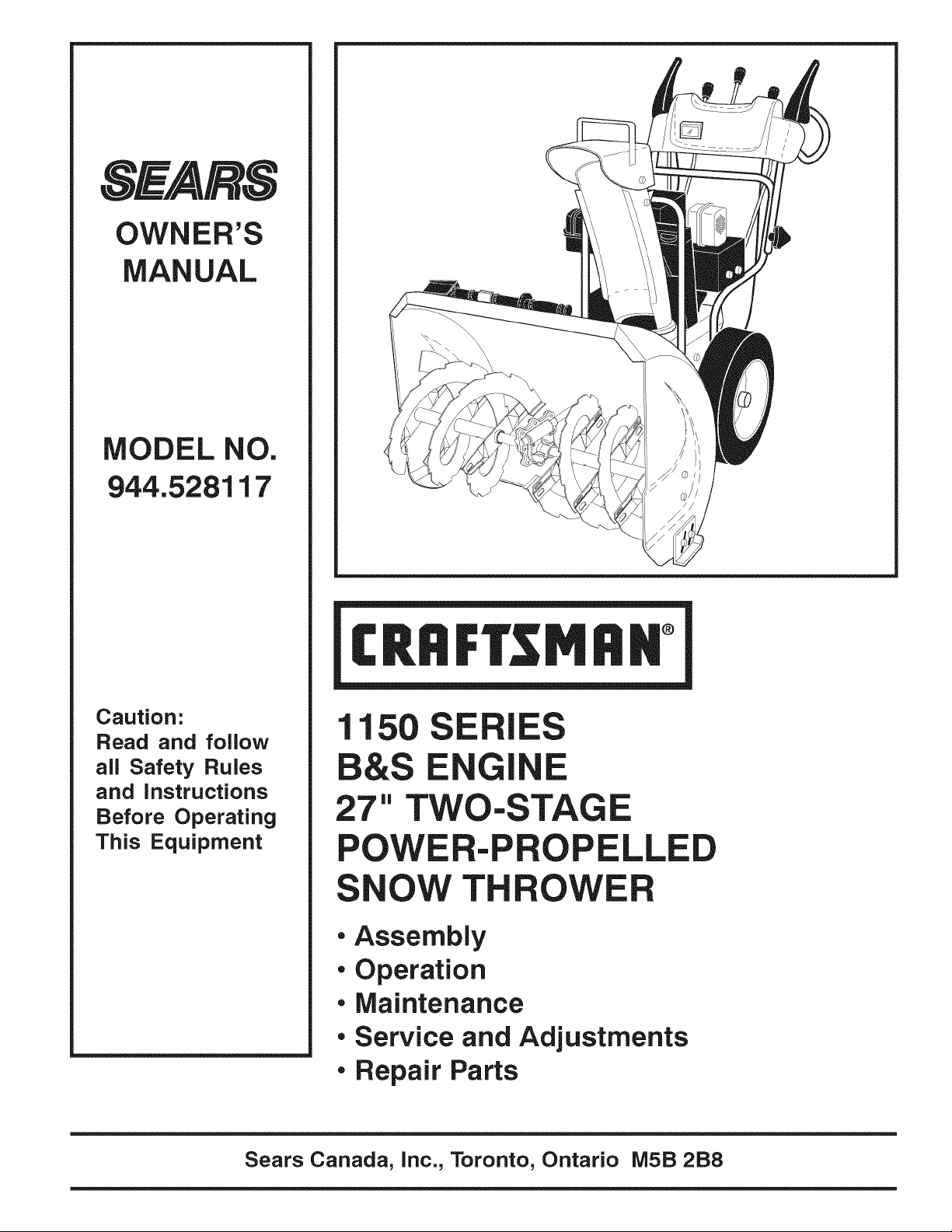
OWNER'S
MANUAL
MODEL NO.
944.528117
!
Caution:
Read and follow
all Safety Rules
and instructions
Before Operating
This Equipment
11 SE
E G
E
27" TWO-STAGE
POWE -P LLE
OW TH
• Assembly
• Operation
• Maintenance
• Service and Adjustments
• Repair Parts
Sears Canada, inc., Toronto, Ontario MSB 2B8
&
&
iMPORTANT
Safe Operation Practices for Walk-Behind Snow Throwers
This snow thrower is capable of amputating hands and feet and throwing objects.
Failure to observe the following safety instructions could result in serious injury.
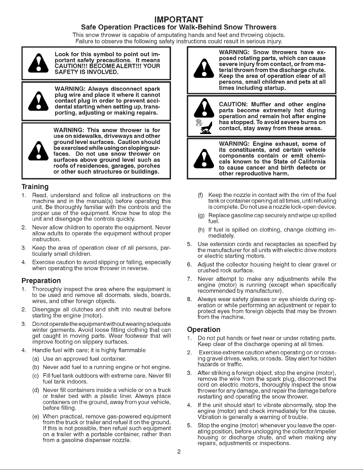
Look for this symbol to point out ira=
portant safety precautions. It means
CAUTION!!! BECOMEALERT!!! YOUR
SAFETY IS INVOLVED.
WARNING: Always disconnect spark
plug wire and place it where it cannot
contact plug in order to prevent acci=
dental starting when setting up, trans-
porting, adjusting or making repairs.
&
WARNING: Snow throwers have ex=
posed rotating parts, which can cause
severe injury from contact, or from ma=
terial thrown from the discharge chute.
Keep the area of operation clear of all
persons, small children and pets at all
times including startup.
CAUTION: Muffler and other engineparts become extremely hot during
operation and remain hot after engine
WARNING: This snow thrower is for
use on sidewalks, driveways and other
ground level surfaces. Caution should
be exercised while using on sloping sur=
faces. Do not use snow thrower on
surfaces above ground level such as
roofs of residences, garages, porches
or other such structures or buildings.
Training
1. Read, understand and follow all instructions on the
machine and in the manual(s) before operating this
unit. Be thoroughly familiar with the controls and the
proper use of the equipment. Know how to stop the
unit and disengage the controls quickly.
2. Never allow children to operate the equipment. Never
allow adults to operate the equipment without proper
instruction.
3. Keep the area of operation clear of all persons, par-
ticularly small children.
4. Exercise caution to avoid slipping or falling, especially
when operating the snow thrower in reverse.
Preparation
1. Thoroughly inspect the area where the equipment is
to be used and remove all doormats, sleds, boards,
wires, and other foreign objects.
2. Disengage all clutches and shift into neutral before
starting the engine (motor).
3. Do not operate the equipment without wearing adequate
winter garments. Avoid loose fitting clothing that can
get caught in moving parts. Wear footwear that will
improve footing on slippery surfaces.
4. Handle fuel with care; it is highly flammable
(a) Use an approved fuel container.
(b) Never add fuel to a running engine or hot engine.
(c) Fill fuel tank outdoors with extreme care. Never fill
fuel tank indoors.
(d) Never fill containers inside a vehicle or on a truck
or trailer bed with a plastic liner. Always place
containers on the ground, away from your vehicle,
before filling.
(e) When practical, remove gas-powered equipment
from the truck or trailer and refuel it on the ground.
If this is not possible, then refuel such equipment
on a trailer with a portable container, rather than
from a gasoline dispenser nozzle.
_ has stopped. To avoid severe burns oncontact, stay away from these areas.
WARNING: Engine exhaust, some of
its constituents, and certain vehicle
components contain or emit chemi=
&
(f) Keep the nozzle in contact with the rim of the fuel
(g) Replace gasoline cap securely and wipe up spilled
(h) If fuel is spilled on clothing, change clothing im-
5.
Use extension cords and receptacles as specified by
the manufacturer for all units with electric drive motors
or electric starting motors.
.
Adjust the collector housing height to clear gravel or
crushed rock surface.
7.
Never attempt to make any adjustments while the
engine (motor) is running (except when specifically
recommended by manufacturer).
.
Always wear safety glasses or eye shields during op-
eration or while performing an adjustment or repair to
protect eyes from foreign objects that may be thrown
from the machine.
cals known to the State of California
to cause cancer and birth defects or
other reproductive harm.
tank orcontainer opening at all times, until refueling
iscomplete. Do not use anozzle lock-open device.
fuel.
mediately.
Operation
1. Do not put hands or feet near or under rotating parts.
Keep clear of the discharge opening at all times.
2. Exercise extreme caution when operating on or cross-
ing gravel drives, walks, or roads. Stay alert for hidden
hazards or traffic.
3. After striking a foreign object, stop the engine (motor),
remove the wire from the spark plug, disconnect the
cord on electric motors, thoroughly inspect the snow
thrower for any damage, and repair the damage before
restarting and operating the snow thrower.
4. If the unit should start to vibrate abnormally, stop the
engine (motor) and check immediately for the cause.
Vibration isgenerally a warning of trouble.
5. Stop the engine (motor) whenever you leave the oper-
ating position, before unclogging the collector/impeller
housing or discharge chute, and when making any
repairs, adjustments or inspections.
2
6. Whencleaning,repairingorinspectingthesnowthrower,
stoptheengineandmakecertainthecollector/impel-
ler andall movingpartshavestopped.Disconnect
thesparkplugwireandkeepthewireawayfromthe
plug.topreventsomeonefromaccidentallystartingthe
engine.
7. Donotruntheengineindoors,exceptwhenstarting
theengineandfortransportingthesnowthrowerinor
outofthebuilding.Opentheoutsidedoors;exhaust
fumesaredangerous.
8. Exerciseextremecautionwhenoperatingonslopes.
9. Neveroperatethesnowthrowerwithoutproperguards,
andothersafetyprotectivedevicesinplaceandwork-
ing.
10.Neverdirectthedischargetowardpeopleor areas
wherepropertydamagecanoccur.Keepchildrenand
othersaway.
11.Donotoverloadthemachinecapacitybyattempting
toclearsnowattoofastarate.
12.Neveroperatethemachineathightransportspeeds
onslipperysurfaces.Lookbehindandusecarewhen
operatinginreverse.
13.Disengagepowertothecollector/impellerwhensnow
throweristransportedornotinuse.
14.Useonlyattachmentsandaccessoriesapprovedby
themanufacturerofthesnowthrower(suchaswheel
weights,counterweights,orcabs).
15.Neveroperatethesnowthrowerwithoutgoodvisibility
orlight.Alwaysbesureofyourfooting,andkeepafirm
holdonthehandles.Walk;neverrun.
16.Nevertouchahotengineormuffler.
Clearing a Clogged Discharge Chute
Hand contact with the rotating impeller insidethe discharge
chute is the most common cause of injuryassociated with
snow throwers. Never use your hand to clean out the dis-
charge chute. To clear the chute:
1. SHUT THE ENGINE OFF!
2. Wait 10 seconds to be sure the impeller blades have
stopped rotating.
3. Always use a clean-out tool, not your hands.
Maintenance and Storage
1. Check shear bolts and other bolts atfrequent intervals
for proper tightness to be sure the equipment is in safe
working condition.
2. Never store the machine with fuel in the fuel tank
inside a building where ignition sources are present
such as hot water heaters, space heaters, or clothes
dryers. Allow the engine to cool before storing in any
enclosure.
3. Always refer to operator's manual for important details
if the snow thrower is to be stored for an extended
period.
4. Maintain or replace safety and instruction labels, as
necessary.
5. Run the machine a few minutes after throwing snow
to prevent freeze-up of the collector/impeller.
CONGRATULATIONSonyourpurchaseofanewsnow
thrower.Ithasbeendesigned,engineeredandmanufac-
turedtogivebestpossibledependabilityandperformance.
Shouldyouexperienceanyproblemyoucannoteasily
remedy,pleasecontactyournearestauthorizedservice
center.Wehavecompetent,well-trainedtechniciansand
thepropertoolstoserviceorrepairthisunit.
Pleasereadandretainthismanual.Theinstructionswill
enableyoutoassembleandmaintainyoursnowthrower
properly.Alwaysobservethe"SAFETYRULES".
SERIALNUMBER:
DATEOFPURCHASE:
THEMODELANDSERIALNUMBERSWILLBEFOUND
ONADECALATTACHEDTOTHEREAROFTHESNOW
THROWERHOUSING.
YOUSHOULDRECORDBOTHSERIALNUMBERAND
DATEOFPURCHASEANDKEEPINASAFEPLACE
FORFUTUREREFERENCE.
TA OF CONTENTS
PRODUCT SPECIFICATIONS
Gasoline Capacity 3.0 Quarts (2,84 Liters)
and Type: Unleaded Regular only
Oil Type SAE 5W-30 or 10W-30
(API SG=SL): Synthetic SAE 5W-30
Oil Capacity: 21 Ounces (0,62 Liters)
Spark Plug:
Gap:
I
Champion QC12YC
0.030" (0,762 mm)
CUSTOMER RESPONSIBILITIES
• Read and observe the safety rules.
• Follow a regular schedule in maintaining, caring for
and using your snow thrower.
• Follow the instructions under "Maintenance" and "Stor-
age" sections of this owner's manual.
SAFETY RULES ........................................................ 2=3
PRODUCT SPECIFICATIONS ...................................... 3
CUSTOMER RESPONSIBILITIES ................................ 3
WARRANTY .................................................................. 4
ASSEMBLY / PRE=OPERATION ............................... 5=8
OPERATION ............................................................ 9-14
MAINTENANCE ..................................................... 15-16
MAINTENANCE SCHEDULE ..................................... 15
SERVICE AND ADJUSTMENTS ........................... 17-19
STORAGE ................................................................... 20
TROUBLESHOOTING ................................................ 21
REPAIR PARTS ..................................................... 22-43
GENERAL: Craftsman products are warranted to be free from defects in materials or workmanship for a specific time period
as set-out below (the "Warranty Period"). Warranties extend to the original purchaser of a Craftsman product only. Purchases
made through an online auction or through any website other than www.sears.ca are excluded. The relevant Warranty Period
commences on the original date of purchase. Within this period, SEARS CANADA, Inc. wilt, at its sole option, repair or replace
any products or components which fail in normal use. Such repairs or replacement will be made at no charge to the customer for
parts or labor, provided that the customer shall be responsible for any transportation cost.
EXCLUSIONS: This warranty does not cover failures due to normal wear, abuse, misuse, neglect (including but not limited to
the use of stale fuel, dirt, abrasives, moisture, rust, corrosion, or any adverse reaction due to improper storage or use habits),
improper maintenance or failure to follow maintenance guidelines and/or instructions, failure to operate the product in accordance
with the owner's manual or any additional instructions or information provided at the time of purchase or in subsequent
communications with the original purchaser, accident or unauthorized alterations or repairs made or attempted by others. Also
excluded from warranty coverage - except as provided below - are the following: maintenance, adjustments, components subject
to wear including but not limited to: cosmetic components, belts, blades, blade adapters, bulbs, tires, filters, guide bars, lubricants,
seats, grips, recoil assy's, saw chains and bars, trimmer lines and spools, spark plugs, starter ropers and tines, and discoloration
resulting from ultraviolet light. Any product missing the model and/or serial number identification label will be disqualified from
coverage under this warranty.
REPAIRS: Repairs have a 90 day warranty. Ifthe defective product is still within the Warranty Period, then the new warranty is 90
days from the date of repair or to the end of the original Warranty Period, whichever period is longer.
DISCLAIMERS: THE WARRANTIES AND REMEDIES CONTAINED HEREIN ARE EXCLUSIVE AND IN LIEU OF ALL OTHER
WARRANTIES, WHETHER ORAL OR WRITTEN (OTHER THAN AS STATED HEREIN), AND WHETHER EXPRESS, IMPLIED
OR STATUTORY, INCLUDING BUT NOT LIMITED TO ANY THIS WARRANTY GIVES YOU SPECIFIC LEGAL RIGHTS, WHICH
MAY VARY FROM PROVINCE TO PROVINCE.
IN NO EVENT SHALL SEARS BE LIABLE FOR ANY INCIDENTAL, SPECIAL, INDIRECT OR CONSEQUENTIAL DAMAGES,
WHETHER RESULTING FROM THE USE, MISUSE OR INABILITY TO USE THE PRODUCT OR FROM DEFECTS IN THE
PRODUCT. THE EXCLUSIONS IN THIS PARAGRAPH SHALL NOT APPLY IN JURISDICATIONS WHERE APPLICABLE LAW
DOES NOT ALLOW FOR THE EXCLUSION OF INCIDENTAL OR CONSEQUENTIAL DAMAGES. IN SUCH JURISDICTIONS,
THIS PARAGRAPH SHALL NOT APPLY, BUT THE REMAINING PROVISIONS OF THIS DOCUMENT SHALL REMAIN VALID.
SEARS retains the exclusive right to repair or replace the product or offer a full refund of the purchase price at its sole discretion.
SUCH REMEDY SHALL BE YOUR SOLE AND EXCLUSIVE REMEDY FOR ANY BREACH OF WARRANTY
CUSTOMER RESPONSIBILITIES: In additional to complying with all suggested maintenance guidelines and instructions,
customers' obligations shall include but shall not be limited to: operating the product in accordance with the owner's manual or
any additional instructions or information provided at the time of purchase or in subsequent communications to the purchaser from
time to time, exhibit reasonable care in the use, operation, maintenance, general upkeep and storage of the product. Failure to
comply with these requirements will void any applicable warranty.
LIST OF APPLICABLE WARRANTY PERIODS: The following list contains the applicable Warranty Period for your Craftsman product
and is based on a combination of the type of product or component and the intended and actual use of the product or component:
1. 90 DAYS: Craftsman products intended for use or actually used for commercial, institutional, professional or income-
producing purposes
2. 2 YEARS: Craftsman riding lawn mowers, yard and garden tractors, walk behind mowers, tillers, brush cutters,
snow blowers, handheld blowers, backpack blowers, hedge trimmers and electrical products for noncommercial,
nonprofessional, non-institutional, or non-income-producing use, except for those components which are part of engine
systems manufactured by third party engine manufacturers for which the purchase has received an separate warranty
with product information supplied at the time of purchase.
3. 1 YEAR: Craftsman power cutters, stump grinders, pole pruners, gas chain saws, electric chain saws, trimmer
attachments, baggers and pole saws for noncommercial, nonprofessional, non-institutional, or non-income-producing use.
4. 90 DAYS: All defective batteries, which will be replaced during this 90-day Warranty Period.
5. 60 DAYS: Additional Warranty Period of 60 days will apply to adjustments and worn products or components BUT DOES
NOT INCLUDE WEAR OR ADJUSTMENTS for products used for commercial, institutional, professional or income-
producing purposes. Wear items include but are not limited to: belts, blades, tires, spark plugs, air filters, chains, shear
bolts, skid plates, scraper bars, drift cutters, ropes, tines, collection bags and pulleys.
As the Warranty Period runs from the date of purchase and NOT from the date that a product is delivered, opened, assembled or
first used, please ensure during this time period that your product or component has been assembled and tested for correction
operation regardless of when you intend to actually use it. Claims made after the Warranty Period has expired will not be honored.
PROOF OF PURCHASE/DOCUMENTATION: Warranty coverage is conditioned upon the original purchaser furnishing SEARS
CANADA or its authorized third party service provider if applicable, with the original sales receipt or other adequate written proof
of the original purchase date and identification of the product. In the event that the original purchaser is unable to provide a
company of the original sales receipt, SEARS CANADA Inc. reserves the right to determine inits sole discretion what other written
proof of the original purchase date and identification of the product is acceptable.
4
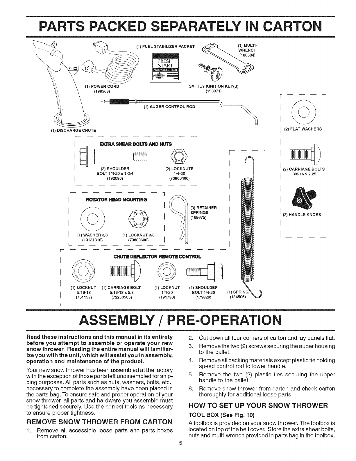
PARTS PACKE E ELY I CARTON
(1) POWER CORD
(1) DISCHARGE CHUTE
÷
ROTATOR HEAD MOUN_NG
(1) FUEL STABILIZER PACKET
FRESH
(198563)
1111111
(1) AUGER CONTROL ROD
EXTRASHF=ARBOLTSANDNUTS I
(2)SHOULDER (2)LOCKNUTSI
BOLT 1/4-20 x 1-3/4 1/4-20
(192090) (73800400) I
SAFTEY IGNmON KEY(S)
(193071)
SPRINGS
(169675)
(1)MULTi-
WRENCH
(i80684)
(2) FLAT WASHERS
(2) CARRIAGE BOLTS
3/8-16 x 2.25
(2) HANDLE KNOBS
J (1) WASHER 3/8 (1) LOCKNUT 3/8
(19131316) (73800600)
[
r
I
CHUTEDF=FtICTOR REMOTECONTROL
I
I
(1) LOCKNUT
5/16-18
I
(751153)
L_
ASS
Read these instructions and this manual in its entirety
before you attempt to assemble or operate your new
snow thrower. Reading the entire manual will familiar=
ize you with the unit, which will assist you in assembly,
operation and maintenance of the product.
Your new snow thrower has been assembled at the factory
with the exception of those parts left unassembled for ship-
ping purposes. All parts such as nuts, washers, bolts, etc.,
necessary to complete the assembly have been placed in
the parts bag. To ensure safe and proper operation of your
snow thrower, all parts and hardware you assemble must
be tightened securely. Use the correct tools as necessary
to ensure proper tightness.
REMOVE SNOW THROWER FROM CARTON
1. Remove all accessible loose parts and parts boxes
from carton.
(1) CARRIAGE BOLT (1) LOCKNUT
5/16-18 x 5/8 1/4-20
(72250505) (191730)
LY/P
(3) RETAINER
(I)SHOULDER
BOLT 1/4-20
(179829) (184505)
E-OPERATIO
2. Cut down all four corners of carton and lay panels flat.
3. Remove the two (2)screws securing the auger housing
to the pallet.
4. Remove all packing materials except plastic tie holding
speed control rod to lower handle.
5. Remove the two (2) plastic ties securing the upper
handle to the pallet.
6. Remove snow thrower from carton and check carton
thoroughly for additional loose parts.
HOW TO SET UP YOUR SNOW THROWER
TOOL BOX (See Fig. 10)
A toolbox is provided on your snow thrower. The toolbox is
located on top ofthe belt cover. Store the extra shear bolts,
nuts and multi-wrench provided in parts bag in the toolbox.
ASSE BLY/PRE-OPERATION
NOTE: The multi-wrench may be used for assembly of the
chute rotator head to snow thrower and making adjustments
to the skid plates.
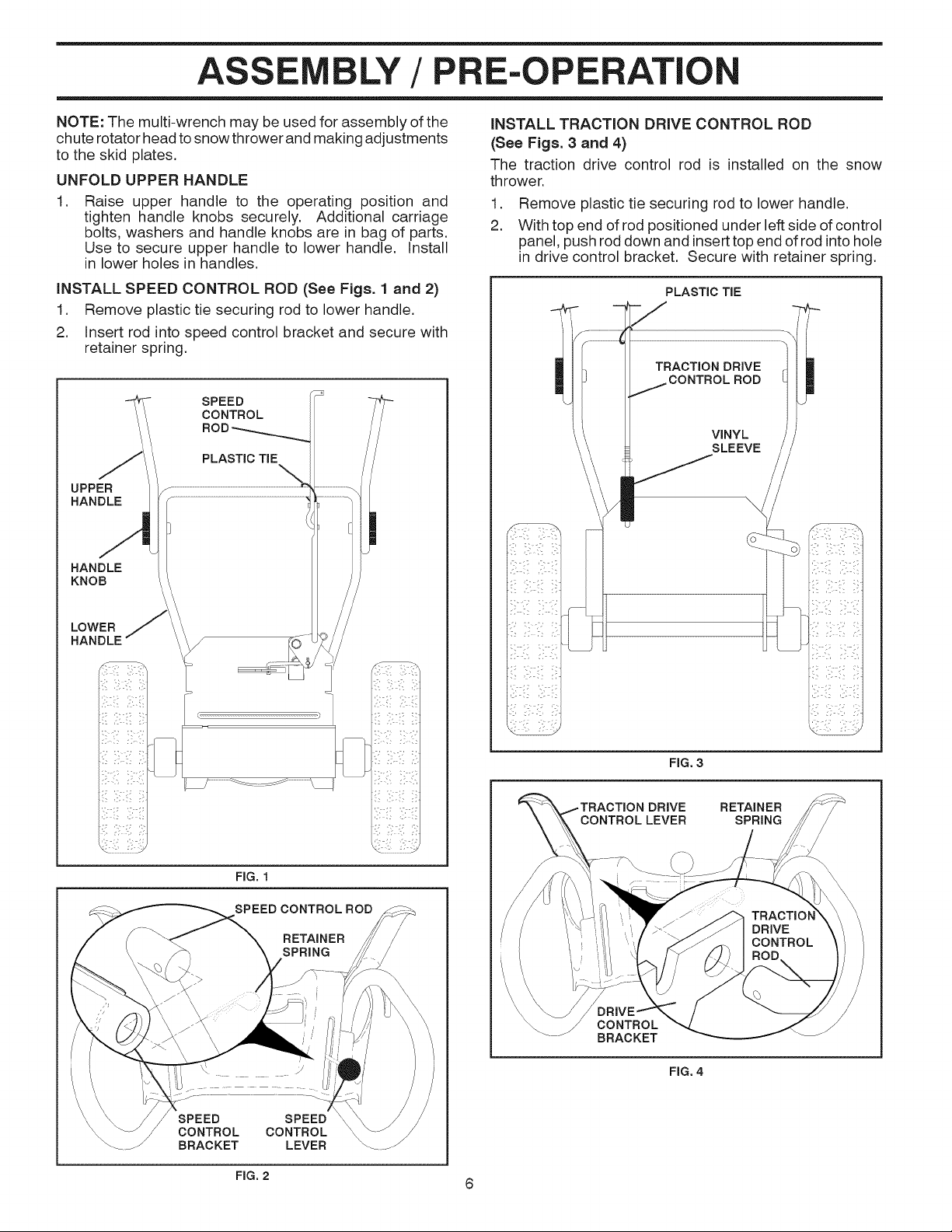
UNFOLD UPPER HANDLE
.
Raise upper handle to the operating position and
tighten handle knobs securely. Additional carriage
bolts, washers and handle knobs are in bag of parts.
Use to secure upper handle to lower handle. Install
in lower holes in handles.
INSTALL SPEED CONTROL ROD (See Figs. 1 and 2)
1. Remove plastic tie securing rod to lower handle.
2. Insert rod intospeed control bracket and secure with
retainer spring.
SPEED
CONTROL
PLASTIC TIE
UPPER
HANDLE
HANDLE
KNOB
INSTALL TRACTION DRIVE CONTROL ROD
(See Figs. 3 and 4)
The traction drive control rod is installed on the snow
thrower.
1. Remove plastic tie securing rod to lower handle.
2. With top end of rod positioned under left side of control
panel, push rod down and inserttop end of rod into hole
in drive control bracket. Secure with retainer spring.
PLASTIC TIE
TRACTION DRIVE
CONTROL ROD
VINYL
SLEEVE
\
LOWER
HANDLE f
I I
FIG. 3
DRIVE RETAINER
SPRING
FIG. 1
SPEED CONTROL ROD
RETAINER
SPRING
CONTROL
BRACKET
FIG. 4
SPEED
CONTROL
BRACKET
SPEED
CONTROL
LEVER
FIG. 2 6
ASS LY / P E-OPERATIC
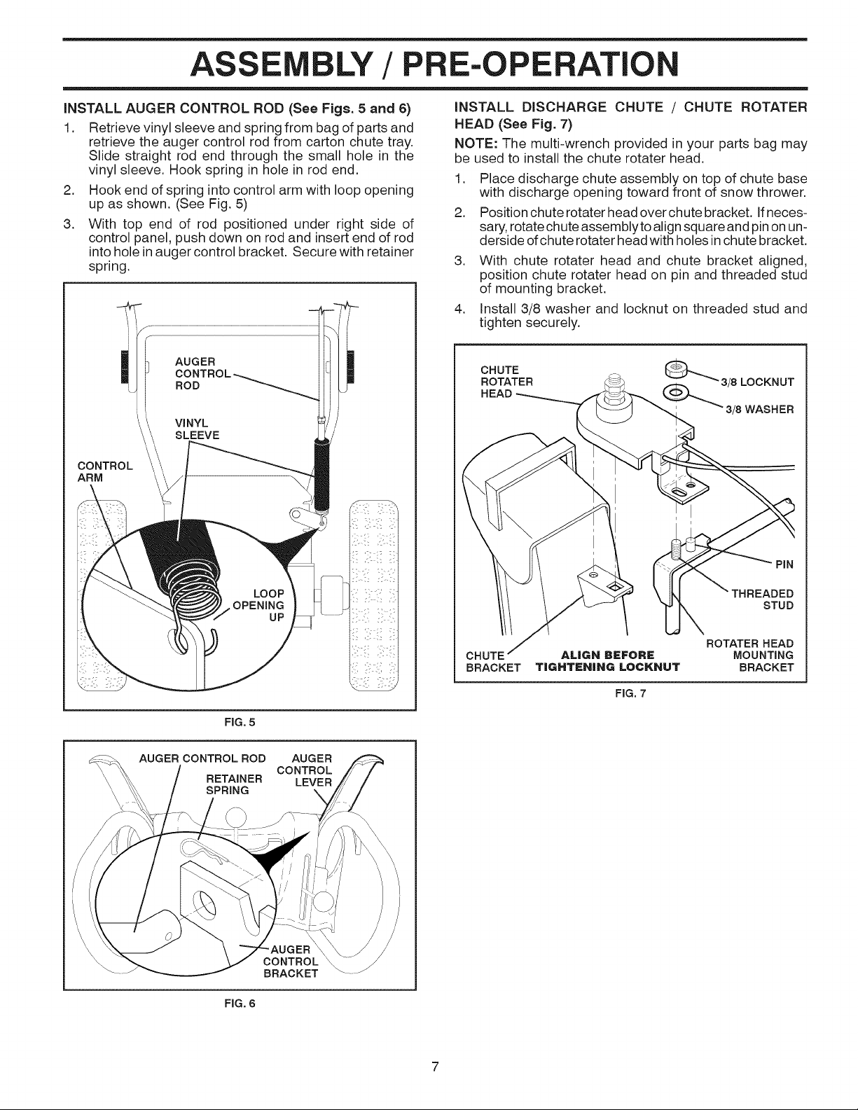
INSTALL AUGER CONTROL ROD (See Figs. 5 and 6)
1. Retrieve vinyl sleeve and spring from bag of parts and
retrieve the auger control rod from carton chute tray.
Slide straight rod end through the small hole in the
vinyl sleeve. Hook spring in hole in rod end.
2. Hook end of spring into control arm with loop opening
up as shown. (See Fig. 5)
3. With top end of rod positioned under right side of
control panel, push down on rod and insert end of rod
into hole in auger control bracket. Secure with retainer
spring.
CONTROL
ARM
INSTALL DISCHARGE CHUTE / CHUTE ROTATER
HEAD (See Fig. 7)
NOTE: The multi-wrench provided in your parts bag may
be used to install the chute rotater head.
1. Place discharge chute assembly on top of chute base
with discharge opening toward front of snow thrower.
2. Position chute rotater head over chute bracket. If neces-
sary, rotate chute assemblyto alignsquare and pinon un-
derside ofchute rotater head with holes in chute bracket.
3. With chute rotater head and chute bracket aligned,
position chute rotater head on pin and threaded stud
of mounting bracket.
4. Install 3/8 washer and Iocknut on threaded stud and
tighten securely.
CHUTE
ROTATER
HEAD
_3/8 LOCKNUT
_3/8 WASHER
FIG. 5
AUGER CONTROL ROD AUGER
CONTROL
RETAINER LEVER
SPRING \
CONTROL
BRACKET
PIN
STUD
ROTATER HEAD
MOUNTING
BRACKET
FIG. 7
FIG. 6
ASSE BLY/PRE-OPERATION
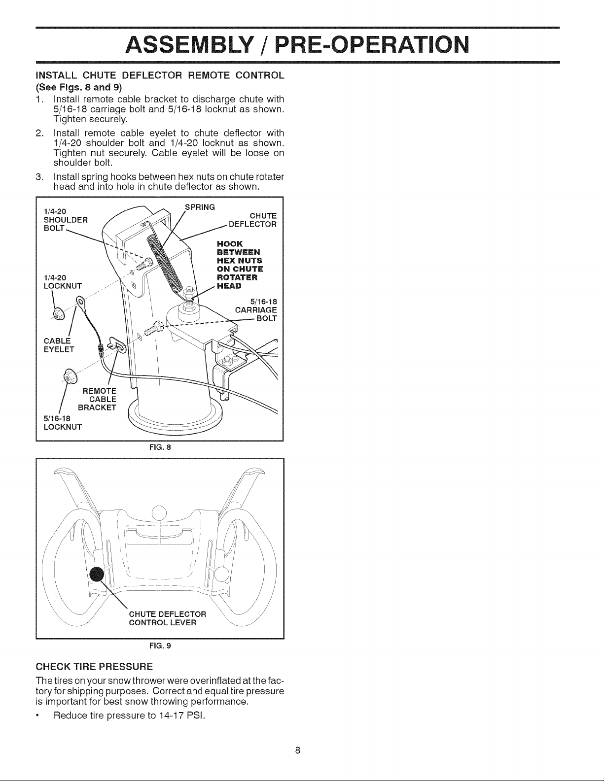
INSTALL CHUTE DEFLECTOR REMOTE CONTROL
(See Figs. 8 and 9)
1. Install remote cable bracket to discharge chute with
5/16-18 carriage bolt and 5/16-18 Iocknut as shown.
Tighten securely.
2. Install remote cable eyelet to chute deflector with
1/4-20 shoulder bolt and 1/4-20 Iocknut as shown.
Tighten nut securely. Cable eyelet will be loose on
shoulder bolt.
.
Install spring hooks between hex nuts on chute rotater
head and into hole in chute deflector as shown.
1/4-20 SPRING
SHOULDER DEFLECTOR
1/4-20
LOCKNUT f_
CABLE
EYELET
REMOTE
/ CABLE
/ BRACKET
5/16-18
LOCKNUT
FIG. 8
CHUTE
CHUTE DEFLECTOR
CONTROLLEVER
FIG, 9
CHECK TIRE PRESSURE
The tires on your snow thrower were overinflated at the fac-
tory for shipping purposes. Correct and equal tire pressure
is important for best snow throwing performance.
• Reduce tire pressure to 14-17 PSI.
8
PE
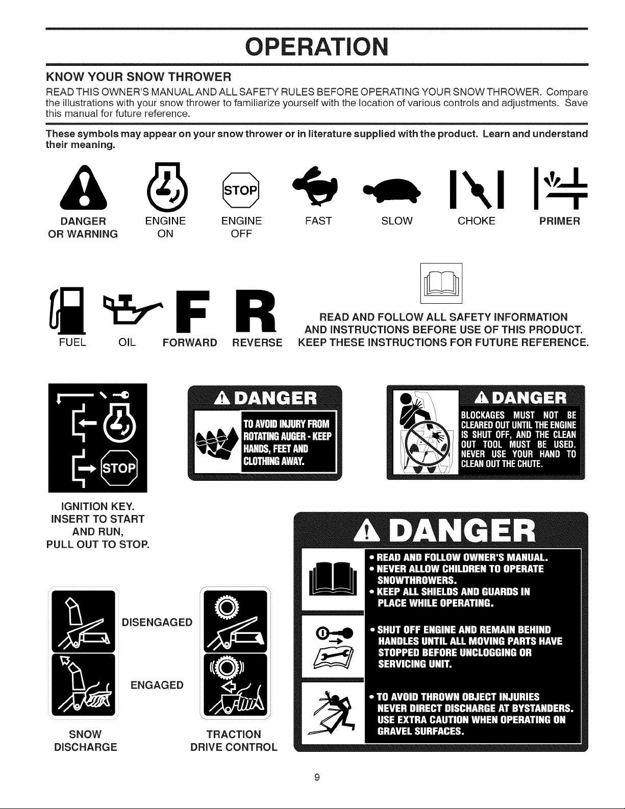
KNOW YOUR SNOW THROWER
READ THIS OWNER'S MANUALAND ALL SAFETY RULES BEFORE OPERATING YOUR SNOWTHROWER. Compare
the illustrations with your snow thrower to familiarize yourself with the location of various controls and adjustments. Save
this manual for future reference.
These symbols may appear on your snow thrower or in literature supplied with the product. Learn and understand
their meaning.
I\1
DANGER ENGINE ENGINE FAST
OR WARNING ON OFF
FUEL OIL FORWARD REVERSE
IGNITION KEY.
INSERT TO START
AND RUN,
PULL OUT TO STOP.
SLOW CHOKE PRIMER
READ AND FOLLOW ALL SAFETY INFORMATION
AND iNSTRUCTiONS BEFORE USE OF THiS PRODUCT.
KEEP THESE iNSTRUCTIONS FOR FUTURE REFERENCE.
SNOW
DISCHARGE
DISENGAGED
ENGAGED
TRACTION
DRIVE CONTROL
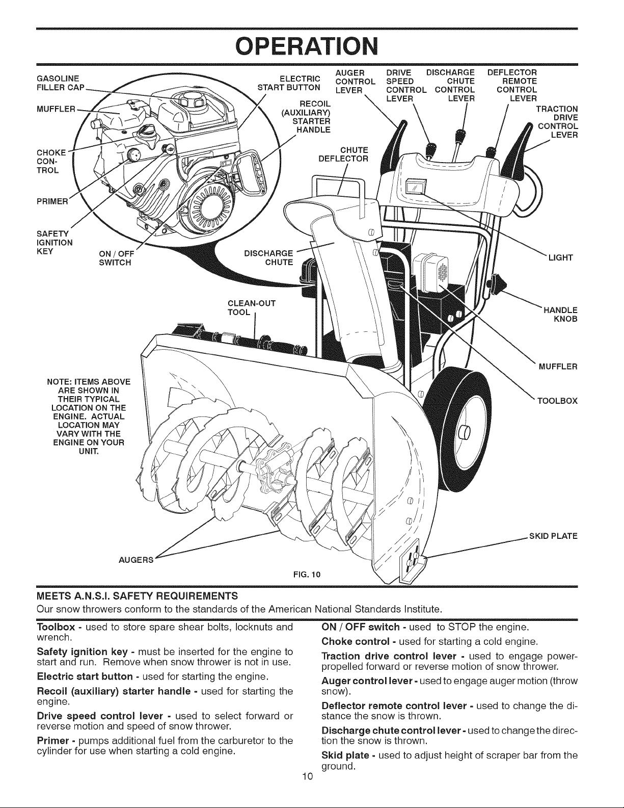
OPERATI
GASOLINE
FILLER
CHOKE"
CON-
TROL
SAFETY
IGNITION
KEY
NOTE: iTEMS ABOVE
ARE SHOWN iN
THEIR TYPICAL
LOCATION ON THE
ENGINE. ACTUAL
LOCATION MAY
VARY WiTH THE
ENGINE ON YOUR
UNIT.
ON / OFF
SWITCH
ELECTRIC
START BUTTON
RECOIL
_UXlLIAR_
STARTER
HANDLE
DISCHARGE
CHUTE
CLEAN-OUT
TOOL
\
AUGER DRIVE DISCHARGE
CONTROL SPEED CHUTE
LEVER CONTROL CONTROL
LEVER LEVER
CHUTE
DEFLECTOR
DEFLECTOR
REMOTE
CONTROL
LEVER
TRACTION
DRIVE
CONTROL
LEVER
HANDLE
KNOB
MUFFLER
TOOLBOX
AUGERS
FIG. 10
MEETS A.N.S.I. SAFETY REQUIREMENTS
Our snow throwers conform to the standards of the American National Standards Institute.
Toolbox - used to store spare shear bolts, Iocknuts and
wrench.
Safety ignition key = must be inserted for the engine to
start and run. Remove when snow thrower is not in use.
Electric start button - used for starting the engine.
Recoil (auxiliary) starter handle - used for starting the
engine.
Drive speed control lever - used to select forward or
reverse motion and speed of snow thrower.
Primer =pumps additional fuel from the carburetor to the
cylinder for use when starting a cold engine.
ON / OFF switch =used to STOP the engine.
Choke control - used for starting a cold engine.
Traction drive control lever - used to engage power-
propelled forward or reverse motion of snow thrower.
Auger control lever - used to engage auger motion (throw
snow).
Deflector remote control lever =used to change the di-
stance the snow is thrown.
Discharge chute control lever - used to change the direc-
tion the snow is thrown.
Skid plate - used to adjust height of scraper bar from the
ground.
10
PLATE
PE
The operation of any snow thrower can result
in foreign objects thrown into the eyes, which
can result insevere eye damage. Always wear
safety glasses or eye shields while operating
your snow thrower or performing any adjust-
ments or repairs. We recommend standard safety glasses
or a wide vision safety mask worn over spectacles.
HOW TO USE YOUR SNOW THROWER
Know how to operate all controls before adding fuel or
attempting to start the engine.
STOPPING
TRACTION DRIVE
• Release traction drive control lever to stop the forward
or reverse movement of the snow thrower.
AUGER
• Release the auger control lever to stop throwing snow.
ENGINE
1. Move ON / OFF switch to "OFF" position.
2. Remove (do not turn) safety ignition key to prevent
unauthorized use.
NOTE: Never use choke to stop engine.
TO USE CHOKE CONTROL (See Fig. 11)
The choke control is located on the engine. Use the choke
control whenever you are starting a cold engine. Do not
use to start a warm engine.
• To engage choke, turn knob clockwise. Slowly turn
knob counterclockwise to disengage.
The DIRECTION in which snow isto be thrown iscontrolled
by the discharge chute control lever.
• Tochange the discharge chute position, press downward
on discharge chute control lever and move lever left
or right until chute is in desired position. Be sure lever
springs back and locks into desired position.
The DISTANCE that snow is thrown is controlled by the
position of the chute deflector. Set the deflector low to
throw snow a short distance; set the deflector higher to
throw snow farther.
Press downward on chute deflector control lever and
move lever forward to lower the deflector and decrease
the distance. Move lever back to raise the deflector
and increase the distance. Be sure lever springs back
and locks into desired position.
DISCHARGE CHUTE
CONTROLLEVER
CHUTE DEFLECTOR
REMOTE CONTROL LEVER
FIG. 12
FIG. 11
TO CONTROL SNOW DISCHARGE (See Fig. 12)
WARNING: Snow throwers have ex=
posed rotating parts, which can cause
severe injury from contact, or from ma=
&
terial thrown from the discharge chute.
Keep the area of operation clear of all
persons, small children and pets at all
times including startup.
WARNING: if the discharge chute or
and wait for all moving parts to stop. Use
auger become clogged, shut=off engine
the clean=out tool, NOT YOUR HANDS,
to unclog the chute and/or auger.
TO THROW SNOW (See Fig. 13)
The auger rotation is controlled by the auger control lever
located on the right side handle.
Squeeze auger control lever to handle to engage the
auger and throw snow.
Release the auger control lever to stop throwing snow.
AUGER
FIG. 13
11
OPERATION
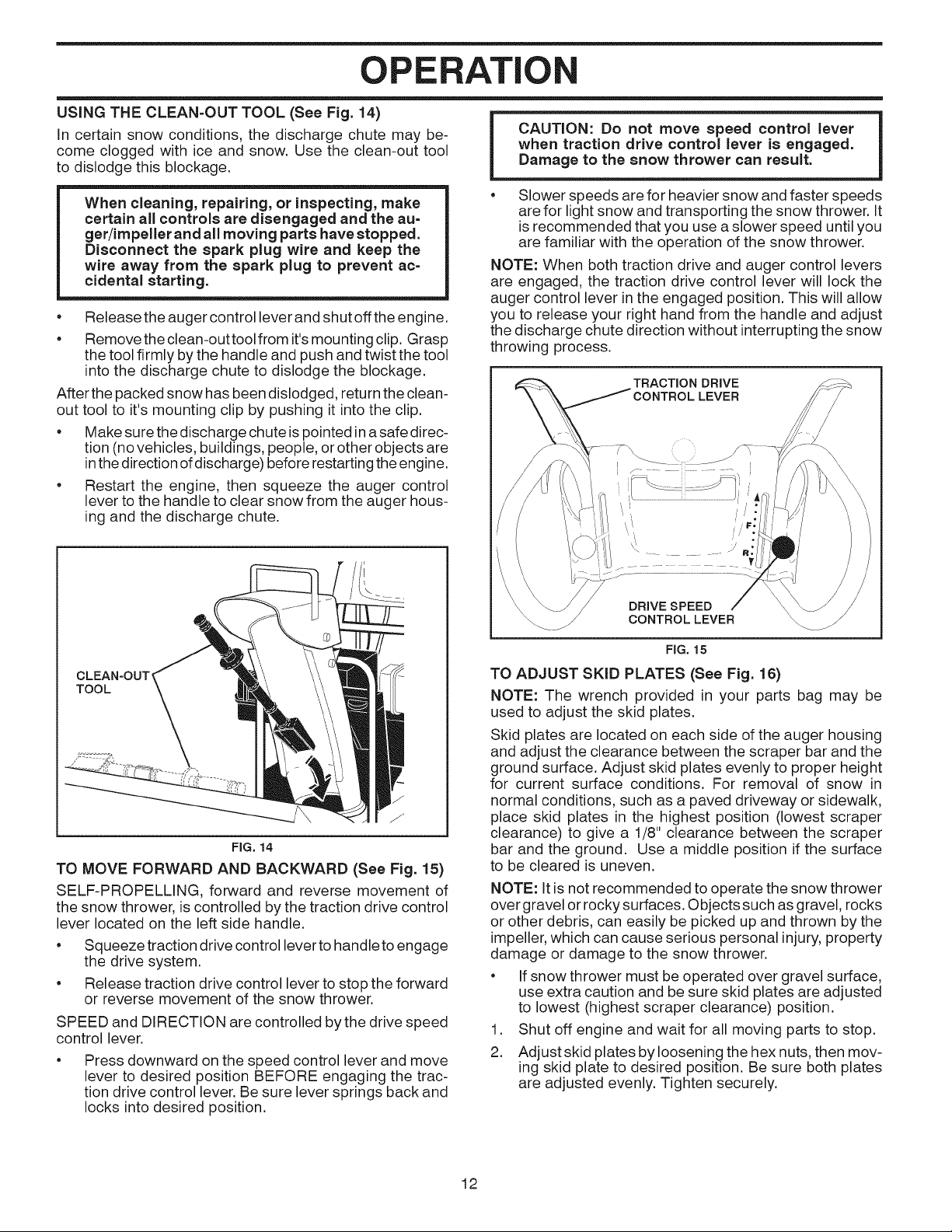
USING THE CLEAN=OUT TOOL (See Fig. 14)
in certain snow conditions, the discharge chute may be-
come clogged with ice and snow. Use the clean-out tool
to dislodge this blockage.
CAUTION: Do not move speed control lever
when traction drive control lever is engaged.
Damage to the snow thrower can result.
When cleaning, repairing, or inspecting, make
certain all controls are disengaged and the au=
ger/impellerand all moving parts have stopped.
Disconnect the spark plug wire and keep the
wire away from the spark plug to prevent ac=
cidental starting.
• Release the auger control lever and shut offthe engine.
• Remove the clean-out toolfrom it's mounting clip. Grasp
the tool firmly by the handle and push and twist the tool
into the discharge chute to dislodge the blockage.
After the packed snow has been dislodged, return the clean-
out tool to it's mounting clip by pushing it into the clip.
• Make sure the discharge chute is pointed in asafe direc-
tion (no vehicles, buildings, people, or other objects are
in the direction of discharge) before restarting the engine.
• Restart the engine, then squeeze the auger control
lever to the handle to clear snow from the auger hous-
ing and the discharge chute.
CLEAN-OUT'
TOOL
FIG. 14
TO MOVE FORWARD AND BACKWARD (See Fig. 15)
SELF-PROPELLING, forward and reverse movement of
the snow thrower, is controlled by the traction drive control
lever located on the left side handle.
• Squeeze traction drive control lever to handle to engage
the drive system.
• Release traction drive control lever to stop the forward
or reverse movement of the snow thrower.
SPEED and DIRECTION are controlled by the drive speed
control lever.
Press downward on the speed control lever and move
lever to desired position BEFORE engaging the trac-
tion drive control lever. Be sure lever springs back and
locks into desired position.
• Slower speeds arefor heavier snow and faster speeds
are for light snow and transporting the snow thrower. It
is recommended that you use a slower speed until you
are familiar with the operation of the snow thrower.
NOTE: When both traction drive and auger control levers
are engaged, the traction drive control lever will lock the
auger control lever in the engaged position. This will allow
you to release your right hand from the handle and adjust
the discharge chute direction without interrupting the snow
throwing process.
TRACTION DRIVE
LEVER
DRaVE SPEED
CONTROLLEVER
FIG. 15
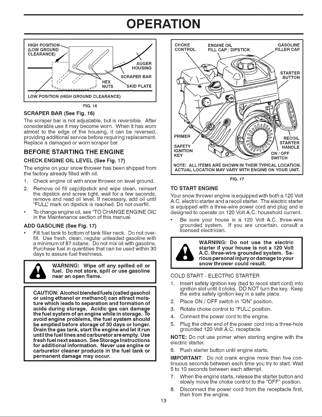
TO ADJUST SKID PLATES (See Fig. 16)
NOTE: The wrench provided in your parts bag may be
used to adjust the skid plates.
Skid plates are located on each side of the auger housing
and adjust the clearance between the scraper bar and the
ground surface. Adjust skid plates evenly to proper height
for current surface conditions. For removal of snow in
normal conditions, such as a paved driveway or sidewalk,
place skid plates in the highest position (lowest scraper
clearance) to give a 1/8" clearance between the scraper
bar and the ground. Use a middle position if the surface
to be cleared is uneven.
NOTE: It is not recommended to operate the snow thrower
over gravel or rocky surfaces. Objects such as gravel, rocks
or other debris, can easily be picked up and thrown by the
impeller, which can cause serious personal injury, property
damage or damage to the snow thrower.
• If snow thrower must be operated over gravel surface,
use extra caution and be sure skid plates are adjusted
to lowest (highest scraper clearance) position.
1. Shut off engine and wait for all moving parts to stop.
2. Adjustskid plates by loosening the hex nuts, then mov-
ing skid plate to desired position. Be sure both plates
are adjusted evenly. Tighten securely.
12
OPERATION
HiGH
(LOW GROUND
AUGER
II HOUSING
'1 .- SCRAPER BAR
-_-_ NUTS PLATE
/
LOW POSiTiON (HIGH GROUND CLEARANCE)
FIG. 16
SCRAPER BAR (See Fig. 16)
The scraper bar is not adjustable, but is reversible. After
considerable use it may become worn. When it has worn
almost to the edge of the housing, it can be reversed,
providing additional service before requiring replacement.
Replace a damaged or worn scraper bar.
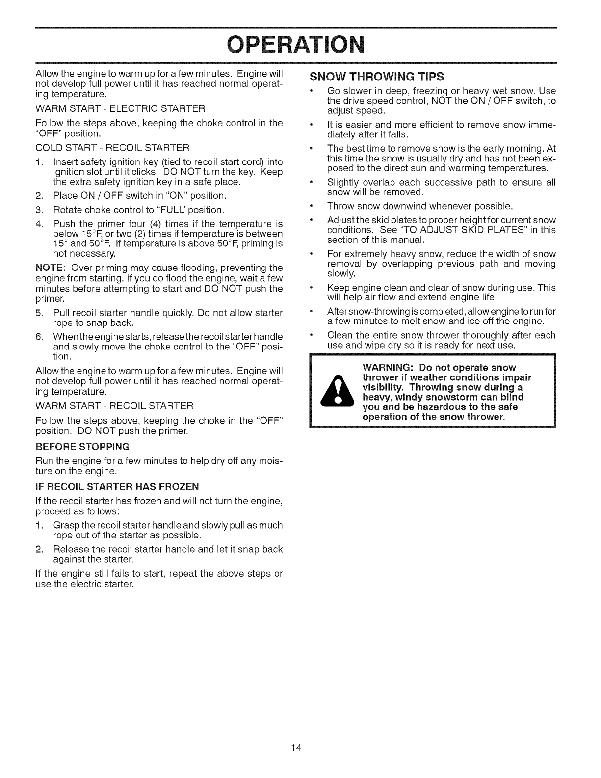
BEFORE STARTING THE ENGINE
CHECK ENGINE OIL LEVEL (See Fig. 17)
The engine on your snow thrower has been shipped from
the factory already filled with oil.
1. Check engine oil with snow thrower on level ground.
2. Remove oil fill cap/dipstick and wipe clean, reinsert
the dipstick and screw tight, wait for a few seconds,
remove and read oil level. If necessary, add oil until
"FULl" mark on dipstick is reached. Do not overfill.
• Tochange engine oil, see "TO CHANGE ENGINE Oil"
in the Maintenance section of this manual.
ADD GASOLINE (See Fig. 17)
• Fill fuel tank to bottom of tank filler neck. Do not over-
fill. Use fresh, clean, regular unleaded gasoline with
a minimum of 87 octane. Do not mix oil with gasoline.
Purchase fuel inquantities that can be used within 30
days to assure fuel freshness.
WARNING: Wipe off any spilled oil or
fuel. Do not store, spill or use gasoline
near an open flame.
CAUTION: Alcohol blended fuels (called gasohol
or using ethanol or methanol) can attract tools=
ture which leads to separation and formation of
acids during storage. Acidic gas can damage
the fuel system of an engine while in storage. To
avoid engine problems, the fuel system should
be emptied before storage of 30 days or longer.
Drain the gas tank, start the engine and let it run
until the fuel lines and carburetor are empty. Use
fresh fuel next season. See Storage instructions
for additional information. Never use engine or
carburetor cleaner products in the fuel tank or
permanent damage may occur.
CHOKE ENGINE OIL GASOLINE
CONTROL FILL CAP / DIPSTICK FILLER CAP
PRIMER RECOIL
SAFETY HANDLE
IGNITION ON / OFF
KEY SWITCH
NOTE: ALL ITEMS ARE SHOWN IN THEIR TYPICAL LOCATION.
ACTUAL LOCATION MAY VARY WiTH ENGINE ON YOUR UNIT.
FIG. 17
TO START ENGINE
Your snow thrower engine is equipped with both a 120 Volt
A.C. electric starter and a recoil starter. The electric starter
is equipped with a three-wire power cord and plug and is
designed to operate on 120 Volt A.C. household current.
• Be sure your house is a 120 Volt A.C. three-wire
grounded system. If you are uncertain, consult a
licensed electrician.
WARNING: Do not use the electric
starter if your house is not a 120 Volt
&
COLD START - ELECTRIC STARTER
1. Insert safety ignition key (tied to recoil start cord) into
ignition slot until it clicks. DO NOT turn the key. Keep
the extra safety ignition key in a safe place.
2. Place ON / OFF switch in "ON" position.
3. Rotate choke control to "FULl" position.
4. Connect the power cord to the engine.
5. Plug the other end of the power cord into a three-hole
grounded 120 Volt A.C. receptacle.
NOTE: Do not use primer when starting engine with the
electric starter.
6. Push starter button until engine starts.
IMPORTANT: Do not crank engine more than five con-
tinuous seconds between each time you try to start. Wait
5 to 10 seconds between each attempt.
7. When the engine starts, release the starter button and
slowly move the choke control to the "OFF" position.
8. Disconnect the power cord from the receptacle first,
then from the engine.
13
A.C. three-wire grounded system. Se-
rious personal injury or damage to your
snow thrower could result.
STARTER
BUTTON
STARTER
OPERATION
Allow the engine to warm up for afew minutes. Engine will
not develop full power until it has reached normal operat-
ing temperature.
WARM START - ELECTRIC STARTER
Follow the steps above, keeping the choke control in the
"OFF" position.
COLD START - RECOIL STARTER
1. Insert safety ignition key (tied to recoil start cord) into
ignitionslot until it clicks. DO NOT turn the key. Keep
the extra safety ignition key in a safe place.
2. Place ON / OFF switch in "ON" position.
3. Rotate choke control to "FULL' position.
4. Push the primer four (4) times if the temperature is
below 15°F, or two (2) times iftemperature is between
15° and 50°R Iftemperature is above 50°F, priming is
not necessary.
NOTE: Over priming may cause flooding, preventing the
engine from starting. If you do flood the engine, wait a few
minutes before attempting to start and DO NOT push the
primer.
5. Pull recoil starter handle quickly. Do not allow starter
rope to snap back.
6. When the engine starts, release the recoil starter handle
and slowly move the choke control to the "OFF" posi-
tion.
Allow the engine to warm up for afew minutes. Engine will
not develop full power until it has reached normal operat-
ing temperature.
WARM START - RECOIL STARTER
Follow the steps above, keeping the choke in the "OFF"
position. DO NOT push the primer.
BEFORE STOPPING
Run the engine for afew minutes to help dry off any mois-
ture on the engine.
iF RECOIL STARTER HAS FROZEN
If the recoil starter has frozen and will not turn the engine,
proceed as follows:
1. Grasp the recoil starter handle and slowly pull as much
rope out of the starter as possible.
2. Release the recoil starter handle and let it snap back
against the starter.
If the engine still fails to start, repeat the above steps or
use the electric starter.
SNOW THROWING TiPS
• Go slower in deep, freezing or heavy wet snow. Use
the drive speed control, NOT the ON / OFF switch, to
adjust speed.
• It is easier and more efficient to remove snow imme-
diately after it falls.
• The best time to remove snow isthe early morning. At
this time the snow is usually dry and has not been ex-
posed to the direct sun and warming temperatures.
• Slightly overlap each successive path to ensure all
snow will be removed.
e
Throw snow downwind whenever possible.
e
Adjust the skid plates to proper height for current snow
conditions. See "TO ADJUST SKID PLATES" in this
section of this manual.
• For extremely heavy snow, reduce the width of snow
removal by overlapping previous path and moving
slowly.
• Keep engine clean and clear of snow during use. This
will help air flow and extend engine life.
• After snow-throwing is completed, allow engine to runfor
a few minutes to melt snow and ice off the engine.
• Clean the entire snow thrower thoroughly after each
use and wipe dry so it is ready for next use.
WARNING: Do not operate snow
thrower if weather conditions impair
&
visibility. Throwing snow during a
heavy, windy snowstorm can blind
you and be hazardous to the safe
operation of the snow thrower.
14
 Loading...