

Craftsman 944527700 Owner’s Manual

OWNER'S
MANUAL
MODEL NO.
944.527700
®
Caution:
Read and follow
all Safety Rules
and instructions
Before Operating
This Equipment
Sears Canada, Inc., Toronto, Ontario MSB 2B8
P
TWO-STAGE
R- ROPELLE
THROWER
• Assembly
• Operation
• Maintenance
• Service and Adjustments
• Repair Parts
&
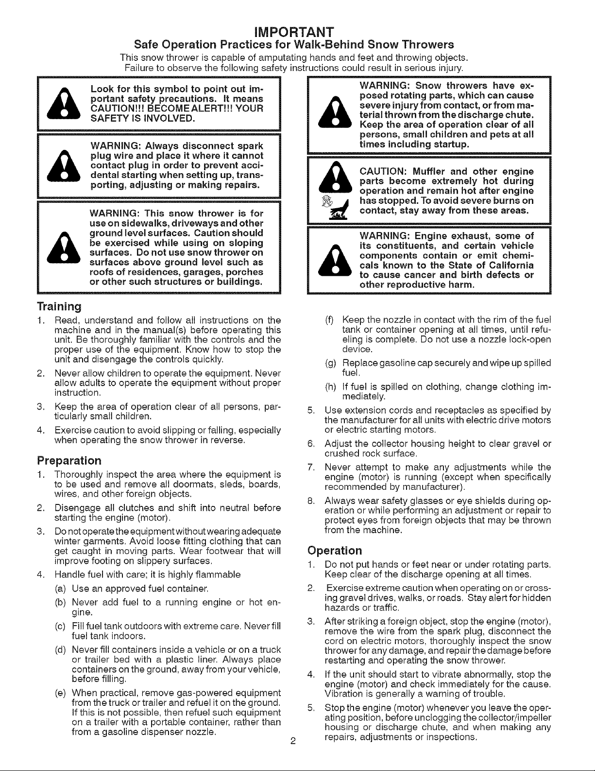
Safe Operation Practices for Walk=Behind Snow Throwers
This snow thrower is capable of amputating hands and feet and throwing objects.
Failure to observe the following safety instructions could result in serious injury.
Look for this symbol to point out im-
portant safety precautions, it means
CAUTION!!! BECOMEALERT!!! YOUR
SAFETY iS iNVOLVED.
WARNING: Always disconnect spark
plug wire and place it where it cannot
contact plug in order to prevent acci=
dental starting when setting up, trans=
porting, adjusting or making repairs.
iMPORTANT
WARNING: Snow throwers have ex=
posed rotating parts, which can cause
terial thrown from the discharge chute.
severe injury from contact, or from ma-
Keep the area of operation clear of all
persons, small children and pets at all
times including startup.
parts become extremely hot during
CAUTION: Muffler and other engine
operation and remain hot after engine
WARNING: This snow thrower is for
use on sidewalks, driveways and other
be exercised while using on sloping
surfaces. Do not use snow thrower on
ground level surfaces. Caution should
surfaces above ground level such as
roofs of residences, garages, porches
or other such structures or buildings.
Training
1, Read, understand and follow all instructions on the
machine and in the manual(s) before operating this
unit. Be thoroughly familiar with the controls and the
proper use of the equipment. Know how to stop the
unit and disengage the controls quickly.
2. Never allow children to operate the equipment. Never
allow adults to operate the equipment without proper
instruction.
3, Keep the area of operation clear of all persons, par-
ticularly small children.
4, Exercise caution to avoid slipping orfalling, especially
when operating the snow thrower in reverse.
Preparation
1, Thoroughly inspect the area where the equipment is
to be used and remove all doormats, sleds, boards,
wires, and other foreign objects.
2. Disengage all clutches and shift into neutral before
starting the engine (motor).
3, Do notoperatethe equipment without wearing adequate
winter garments. Avoid loose fitting clothing that can
get caught in moving parts. Wear footwear that will
improve footing on slippery surfaces.
4, Handle fuel with care; it is highly flammable
(a) Use an approved fuel container.
(b) Never add fuel to a running engine or hot en-
gine.
(c) Fill fuel tank outdoors with extreme care. Never fill
fuel tank indoors.
(d) Never fill containers inside a vehicle or on a truck
or trailer bed with a plastic liner. Always place
containers onthe ground, away from your vehicle,
before filling.
(e) When practical, remove gas-powered equipment
from the truck or trailer and refuel it on the ground.
If this is not possible, then refuel such equipment
on a trailer with a portable container, rather than
from a gasoline dispenser nozzle.
_ has stopped. To avoid severe burns on
(f) Keep the nozzle in contact with the rim of the fuel
(g) Replace gasoline cap securely and wipe up spilled
(h) If fuel is spilled on clothing, change clothing im-
5,
Use extension cords and receptacles as specified by
the manufacturer for all units with electric drive motors
or electric starting motors.
6,
Adjust the collector housing height to clear gravel or
crushed rock surface.
7,
Never attempt to make any adjustments while the
engine (motor) is running (except when specifically
recommended by manufacturer).
8,
Always wear safety glasses or eye shields during op-
eration or while performing an adjustment or repair to
protect eyes from foreign objects that may be thrown
from the machine.
contact, stay away from these areas.
WARNING: Engine exhaust, some of
components contain or emit chemi=
cals known to the State of California
its constituents, and certain vehicle
to cause cancer and birth defects or
other reproductive harm.
tank or container opening at all times, until refu-
eling is complete. Do not use a nozzle lock-open
device.
fuel.
mediately.
Operation
1, Do not put hands or feet near or under rotating parts,
Keep clear of the discharge opening at all times.
2. Exercise extreme caution when operating on or cross-
ing gravel drives, walks, or roads, Stay alert for hidden
hazards or traffic.
3, After striking a foreign object, stop the engine (motor),
remove the wire from the spark plug, disconnect the
cord on electric motors, thoroughly inspect the snow
thrower for any damage, and repair the damage before
restarting and operating the snow thrower.
4. If the unit should start to vibrate abnormally, stop the
engine (motor) and check immediately for the cause.
Vibration is generally a warning of trouble.
5, Stop the engine (motor) whenever you leave the oper-
ating position, before unclogging the collector/impeller
housing or discharge chute, and when making any
repairs, adjustments or inspections,

6. Whencleaning,repairingor inspectingthe snow
thrower,stoptheengineandmakecertainthecol-
lector/impellerandall movingpartshavestopped.
Disconnectthesparkplugwireandkeepthewireaway
fromtheplugtopreventsomeonefromaccidentally
startingtheengine.
7. Donotruntheengineindoors,exceptwhenstarting
theengineandfortransportingthesnowthrowerinor
outofthebuilding.Opentheoutsidedoors;exhaust
fumesaredangerous.
8. Exerciseextremecautionwhenoperatingonslopes.
9. Neveroperatethesnowthrowerwithoutproperguards,
andothersafetyprotectivedevicesinplaceandwork-
ing.
10.Neverdirectthedischargetowardpeopleor areas
wherepropertydamagecanoccur.Keepchildrenand
othersaway.
11.Donotoverloadthemachinecapacitybyattempting
toclearsnowattoofasta rate.
12.Neveroperatethemachineathightransportspeeds
onslipperysurfaces.Lookbehindandusecarewhen
operatinginreverse.
13.Disengagepowertothecollector/impellerwhensnow
throweristransportedornotinuse.
14.Useonlyattachmentsandaccessoriesapprovedby
themanufacturerofthesnowthrower(suchaswheel
weights,counterweights,orcabs).
15.Neveroperatethesnowthrowerwithoutgoodvisibility
orlight.Alwaysbesureofyourfooting,andkeepa
firmholdonthehandles.Walk;neverrun.
16.Nevertoucha hotengineormuffler.
Clearing a Clogged Discharge Chute
Hand contact with the rotating impeller inside the discharge
chute is the most common cause of injury associated with
snow throwers. Never use your hand to clean out the dis-
charge chute. To clear the chute:
1. SHUTTHE ENGINE OFF!
2. Wait 10 seconds to be sure the impeller blades have
stopped rotating.
3. Always use a clean-out tool, not your hands.
Maintenance and Storage
1. Check shear bolts and other bolts at frequent intervals
for proper tightness to be sure the equipment is in safe
working condition.
2. Never store the machine with fuel in the fuel tank
inside a building where ignition sources are present
such as hot water heaters, space heaters, or clothes
dryers. Allow the engine to cool before storing in any
enclosure.
3, Always refer to operator's manual for important details
if the snow thrower is to be stored for an extended
period,
4, Maintain or replace safety and instruction labels, as
necessary,
5, Run the machine a few minutes after throwing snow
to prevent freeze-up of the collector/impeller,
TABLE OF CONTENTS
SAFETY RULES ........................................................ 2-3
PRODUCT SPECiFICATiONS ...................................... 4
CUSTOMER RESPONSIBILITIES ................................ 4
WARRANTY .................................................................. 4
ASSEMBLY / PRE-OPERATION ............................... 6-8
OPERATION ............................................................ 9=14
MAINTENANCE ..................................................... 15-16
MAINTENANCE SCHEDULE ..................................... 15
SERVICE AND ADJUSTMENTS ........................... 17=19
STORAGE ................................................................... 19
TROUBLESHOOTING ................................................ 20
REPAIR PARTS ..................................................... 22-38
SEARS SERVICE ................................... BACK COVER

LIMITED TWO (2) YEAR WARRANTY ON CRAFTSMAN SNOW THROWER
For two (2) years from date of purchase Sears Canada, Inc. will repair or replace, at Sears option, free of charge
parts which are defective as a result of material or workmanship,
COMMERCIAL OR RENTAL USE:
Warranty on Snow Thrower will be 90 days from date of purchase if used for commercial or rental purposes,
This Warranty does NOT cover:
1. Pre=delivery set=up.
2. Expendable items which become worn during normal use, such as belts, spark plugs, air cleaners,
and shear pins, as well damage to the engine resulting from operating snow thrower with insufficient oil.
3. Repairs necessary because of operator abuse or negligence, including the failure to operate and main=
tain the equipment according to the instructions contained in the Owner's Manual.
4. Tire replacement or repair caused by punctures from outside objects, such as nails, thorns, stumps or glass.
Warranty service is available by returning the Craftsman Snow Thrower to the nearest Sears Service Centre/Depart-
ment in Canada. This warranty applies only while this product is in use in Canada.
This warranty is in addition to any statutory warranty and does NOT exclude or limit legal rights you may have but
shalll run concurrently with applicable provincial legislation. Furthermore, some provinces do not allow limitations
on how long an implied warranty will last, so the above limitations may not apply to you,
Sears Canada, inc., Toronto, Ontario M5B 2B8
CONGRATULATIONS on your purchase of a new snow
thrower. It has been designed, engineered and manufac-
tured to give best possible dependability and performance.
Should you experience any problem you cannot easily
remedy, please contact your nearest Sears service centre/
department. We have competent, well-trained technicians
and the proper tools to service or repair this unit.
Please read and retain this manual. The instructions will
enable you to assemble and maintain your snow thrower
properly. Always observe the "SAFETY RULES",
SERIAL NUMBER:
DATE OFPURCHASE:
THE MODELAND SERIAL NUMBERSWILL BE FOUND
ON ADECALATTACH EDTOTHE REAR OFTHE SNOW
THROWER HOUSING.
YOUSHOULDRECORDBOTHSERIALNUMBERAND
DATE OF PURCHASE AND KEEPIN A SAFE PLACE
FOR FUTURE REFERENCE.
PRODUCT SPECiFiCATiONS
Gasoline Capacity 4.0 Quarts (4,54 Liters)
and Type: Unleaded Regular only
Oil Type SAE 5W-30 or 10W-30
(APl SG-SL): (0°F to +40°F / -18°C to +5°C)
Synthetic SAE 5W-30 or 10W-30
(below 0°F / -18°C)
Oil Capacity: 28 Ounces (0,8 Liters)
Spark Plug: Champion RC12YC
Gap: 0,030" (0,762 mm)
CUSTOMER RESPONSIBiLiTiES
• Read and observe the safety rules,
• Follow a regular schedule in maintaining, caring for
and using your snow thrower,
• Follow the instructions under "Maintenance" and "Stor-
age" sections of this owner's manual,

PARTS PACKED SEPARATELY I CARTON
(1) POWER
(1) DISCHARGE CHUTE
EXTRA SHEAR DOLTS AND NUTS
CORD
(1) FUEL STABiLiZER PACKET
(2) SAFETY iGNiTiON KEYS
(1) AUGER CONTROL ROD
1111111
(1) TRACTION DRIVE CONTROL ROD
©
(1) MULTi=
WRENCH
(2) SHEAR BOLTS 1/4=20 x %3/4
ROTATOR HEAD MOUNTING
(1) WASHER 3/8 (1) LOCKNUT 3/8
(1) LOCKNUT
5/16=18
(1) CARRIAGE
BOLT 5/16=18 x 5/8
(2) SPACERS (2) LOCKNUTS
1/4=20
CHUTE DEFLECTOR REMOTE CONTROL
(1) LOCKNUT (1) NYLON
1/4-20 WASHER
(3) RETAINER
SPRINGS
{1) SHOULDER
BOLT 1/4=20
(1)

AS / RE-O ERATION
Read these instructions and this manual in its entirety
before you attempt to assemble or operate your new
snow thrower. Reading the entire manual will familiar=
ize you with the unit, which will assist you inassembly,
operation and maintenance of the product.
Your new snow thrower has been assembled at the factory
with the exception of those parts left unassembled for ship-
ping purposes. All parts such as nuts, washers, bolts, etc.,
necessary to complete the assembly have been placed in
the parts bag. To ensure safe and proper operation of your
snow thrower, all parts and hardware you assemble must
be tightened securely. Use the correct tools as necessary
to ensure proper tightness.
REMOVE SNOW THROWER FROM CARTON
1. Remove all accessible loose parts and parts boxes
from carton.
2. Cut down all four corners of carton and lay panels flat.
3. Remove the two (2) screws securing the auger housing
to the pallet.
4. Remove all packing materials except plastic tie holding
speed control rod to lower handle.
5. Remove the two (2) plastic ties securing the upper
handle to the pallet.
6. Remove snow thrower from carton and check carton
thoroughly for additional loose parts.
INSTALL SPEED CONTROL ROD (See Figs. 1 and 2)
1. Remove plastic tie securing rod to lower handle.
2. insert rod into speed control bracket and secure with
retainer spring.
SPEED
CONTROL
ROD //
PLASTIC TIE
UPPER
HANDLE
/ /
/ /
i
HANDLE
KNOB
LOWER
HANDLE
J
HOW TO SET UP YOUR SNOW THROWER
TOOL BOX (See Fig, 10)
A toolbox is provided on your snow thrower. The toolbox is
located on top of the belt cover. Store the extra shear bolts,
nuts and multi-wrench provided inparts bag in the toolbox.
NOTE: The multi-wrench may be used for assembly of the
chute rotator head tosnow thrower and making adjustments
to the skid plates.
UNFOLD UPPER HANDLE
1. Raise upper handle tothe operating position and tighten
handle knobs securely.
FIG. 1
SPEED CONTROL ROD
RETAINER
SPRING
SPEED SPEED
CONTROL CONTROL
BRACKET LEVER
FIG. 2

AS / RE-O ERATION
INSTALL TRACTION DRIVE CONTROL ROD
(See Figs. 3 and 4)
The traction drive control rod has the long loop on the end
of the spring as shown.
1. Slide rubber sleeve up rod and hook end ofspring into
pivot bracket with loop opening down as shown.
2. With top end of rod positioned under left side of control
panel, push rod down and insert top end of rodinto hole
in drive control bracket. Secure with retainer spring.
LOOP
OPENING
DOWN
INSTALL AUGER CONTROL ROD (See Figs. 5 and 6)
The auger control rod has the short loop on the end of the
spring as shown.
1. Slide rubber sleeve up rod and hook end ofspring into
control arm with loop opening up as shown.
2. With top end of rod positioned under right side of
control panel, push down on rod and insert end of rod
into hole in auger control bracket. Secure with retainer
spring.
AUGER
ROD
RUBBER
SLEEVE
CONTROL
ARM
CONTROL
BRACKET
FIG. 3
FIG, 4
RETAINER
SPRING
FIG. 5
AUGER CONTROL ROD AUGER
CONTROL
RETAINER LEVER
SPRING \
CONTROL
BRACKET
FIG. 6
AS BLY / RE-O ERATION
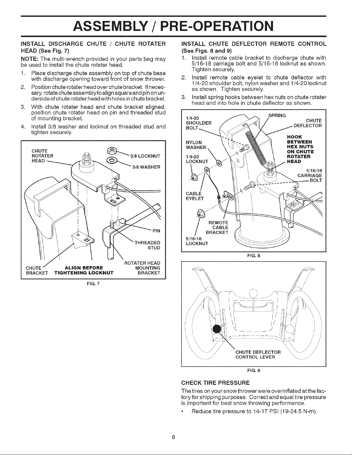
iNSTALL DISCHARGE CHUTE / CHUTE ROTATER
HEAD (See Fig. 7)
NOTE: The multi-wrench provided in your parts bag may
be used to install the chute rotater head,
1, Place discharge chute assembly on top of chute base
with discharge opening toward front of snow thrower,
2, Position chute rotater head overchute bracket, Ifneces-
sary, rotatechute assembly toalign square and pin onun-
derside of chute rotater head with holes inchute bracket,
3, With chute rotater head and chute bracket aligned,
position chute rotater head on pin and threaded stud
of mounting bracket,
4, Install 3/8 washer and Iocknut on threaded stud and
tighten securely,
CHUTE
ROTATER
iNSTALL CHUTE DEFLECTOR REMOTE CONTROL
(See Figs. 8 and 9)
1, Install remote cable bracket to discharge chute with
5/16-18 carriage bolt and 5/16-18 Iocknut as shown,
Tighten securely,
2, Install remote cable eyelet to chute deflector with
1/4-20 shoulder bolt, nylon washer and 1/4-20 Iocknut
as shown, Tighten securely,
3, Install spring hooks between hex nuts on chute rotater
head and into hole in chute deflector as shown,
1/4-20 CHUTE
SHOULDER
NYLON BETWEEN
WASHER HEX NUTS
1/4-20 ROTATER
LOCKNUT
CABLE
EYELET
SPRING
HOOK
ON CHUTE
5/16- ! 8
CARRIAGE
BOLT
FIG. 7
PIN
STUD
ROTATER HEAD
MOUNTING
BRACKET
_B _EMOTE
CABLE
RACKET
5/16-18
LOCKNUT
FiG. 8
// //
CHUTE DEFLECTOR
CONTROL LEVER
FIG. 9
CHECK TiRE PRESSURE
The tires on your snow thrower were overinflated at the fac-
tory for shipping purposes. Correct and equal tire pressure
is important for best snow throwing performance,
• Reduce tire pressure to 14-17 PSi (19-24,5 N-m),

OPERATION
KNOW YOUR SNOW THROWER
READ THIS OWNER'S MANUALAND ALL SAFETY RULES BEFORE OPERATING YOUR SNOWTHROWER. Compare
the illustrations with your snow thrower to familiarize yourself with the location of various controls and adjustments, Save
this manual for future reference,
These symbols may appear on your snow thrower or in literature supplied with the product. Learn and understand
their meaning,
I\1
DANGER ENGINE FAST SLOW CHOKE PRIMER
OR WARNING ON
FUEL OIL FORWARD REVERSE
IGNITION KEY.
INSERT TO START
AND RUN,
PULL OUT TO STOP.
ENGINE
OFF
R
READ AND FOLLOW ALL SAFETY INFORMATION
AND INSTRUCTIONS BEFORE USE OF THIS PRODUCT.
KEEP THESE INSTRUCTIONS FOR FUTURE REFERENCE.
\ J
SNOW
DISCHARGE
DISENGAGED
ENGAGED
_J
TRACTION
DRIVE CONTROL

O ERATION
GASOLINE ELECTRIC AUGER DISCHARGE CHUTE CONTROL LEVER
CHOKE DEFLECTOR CONTROL
CON- LEVER
TROL
SAFETY
IGNITION
KEY
NOTE: ITEMS ABOVE
ARE SHOWN IN
THEIR TYPICAL
LOCATION ON THE
ENGINE. ACTUAL
LOCATION MAY VARY
WITH THE ENGINE
ON YOUR UNIT.
ON / OFF
SWITCH
CLEAN-OUT TOOL i
\
START BUTTON CONTROL
CHUTE
LEVER DRIVE SPEED DEFLECTOR REMOTE
RECOIL X CONTROL LEVER CONTROL LEVER
STARTER
HANDLE
CHUTE DRIVE
\
'TRACTION
_HTURN
TRIGGER
LIGHT
HANDLE
KNOB
TOOLBOX
CONTROL
FIG. 10
MEETS A,N,S,I, SAFETY REQUIREMENTS
Our snow throwers conform to the standards of the American National Standards Institute,
Toolbox = used to store spare shear bolts, Iocknuts and
wrench,
Safety ignition key - must be inserted for the engine to
start and run, Remove when snow thrower is not in use,
Electric start button - used for starting the engine,
Recoil (auxiliary) starter handle- used forstarting engine,
Primer - pumps additional fuel from the carburetor to the
cylinder for use when starting a cold engine,
Choke Control - used for starting a cold engine,
ON / OFF switch =used to STOP the engine,
Freewheel control - disengages transmission for pushing
the snowthrower with the engine off,
LH and RH turn triggers - used to steer the snow thrower,
Drive speed control lever - used to select forward or
reverse motion and speed of snow thrower,
Traction drive control lever- used to engage power-pro-
pelled forward or reverse motion of snow thrower,
Auger control lever - used to engage auger motion
(throw snow),
Discharge chute control lever - used to change the
direction the snow is thrown,
Deflector remote control lever - used to change the
distance the snow is thrown,
Skid plate - used to adjust height of scraper barfrom ground,
10
Drift cutter - used to cut through deep snowdrifts,
DRIFT CUTTER
PLATE

OPERATION
The operation of any snow thrower can result
in foreign objects thrown into the eyes, which
can result insevere eyedamage. Always wear
safety glasses or eye shields while operating
your snow thrower or performing any adjust-
ments or repairs. We recommend standard safety glasses
or a wide vision safety mask worn over spectacles.
HOW TO USE YOUR SNOW THROWER
Know how to operate all controls before adding fuel or
attempting to start the engine.
STOPPING
TRACTION DRIVE
• Release traction drive control lever to stop the forward
or reverse movement of the snow thrower.
AUGER
• Release the auger control lever to stop throwing snow.
ENGINE
1. Move ON / OFF switch to "OFF" position.
2. Remove (do not turn) safety ignition key to prevent
unauthorized use.
NOTE: Never use choke to stop engine.
TO USE THROTTLE CONTROL (See Fig. 11)
The throttle control islocated on the engine. Always operate
the snow thrower with the engine at full throttle. Full throttle
offers the best snow thrower performance.
TO CONTROL SNOW DISCHARGE (See Fig. 13)
WARNING: Snow throwers have ex-
posed rotating parts, which can cause
terial thrown from the discharge chute.
severe injuryfrom contact, or from ma-
Keep the area of operation clear of all
persons, small children and pets at all
times including startup.
WARNING: If the discharge chute or au-
and wait for all moving parts to stop. Use
get become clogged, shut-off engine
the clean=out tool, NOT YOUR HANDS,
to unclog the chute and/or auger.
The DIRECTION inwhich snow isto be thrown iscontrolled
by the discharge chute control lever.
• Tochangethe discharge chute position, press downward
on discharge chute control lever and move lever left
or right until chute is in desired position. Be sure lever
springs back and locks into desired position.
The DISTANCE that snow is thrown is controlled by the
position of the chute deflector. Set the deflector low to
throw snow a short distance; set the deflector higher to
throw snow farther.
Press downward on chute deflector control lever and
move lever forward to lower the deflector and decrease
the distance. Move lever back to raise the deflector
and increase the distance. Be sure lever springs back
and locks into desired position.
(, )
SLOW FAST
FIG, 11
TO USE CHOKE CONTROL (See Fig. 12)
The choke control is located on the engine. Use the choke
control whenever you are starting a cold engine. Do not
use to start a warm engine.
• To engage choke, turn knob counterclockwise. Slowly
turn knob clockwise to disengage.
(
DISCHARGECHUTE
CONTROLLEVER
CHUTE DEFLECTOR
REMOTE CONTROLLEVER
FIG, 13
TO THROW SNOW (See Fig. 14)
The auger rotation is controlled by the auger control lever
located on the right side handle.
• Squeeze auger control lever to handle to engage the
auger and throw snow.
• Release the auger control lever to stop throwing snow.
OFF I\lFULL
FIG. 12 1 1 FIG. 14
OPERATION
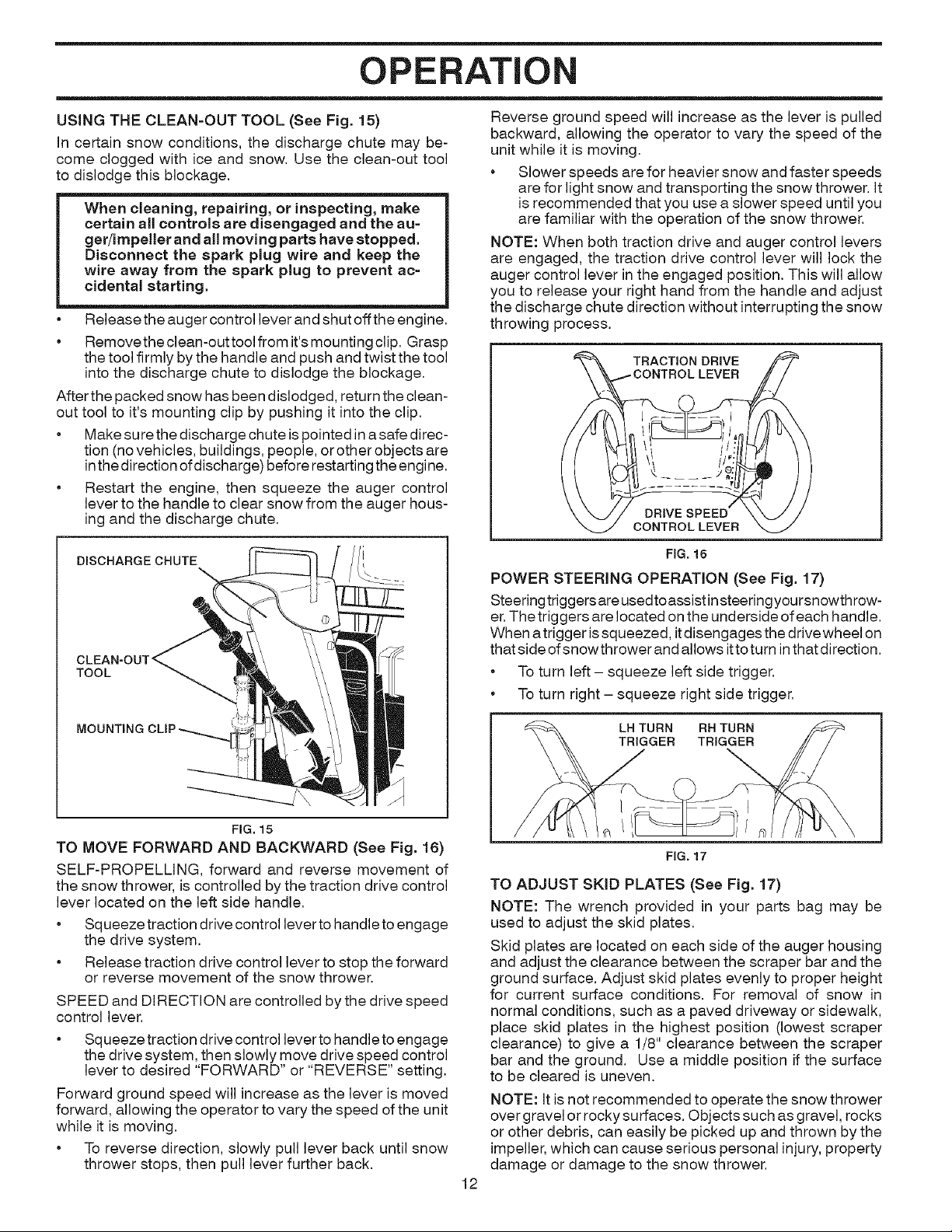
USING THE CLEAN-OUT TOOL (See Fig. 15)
in certain snow conditions, the discharge chute may be-
come clogged with ice and snow. Use the clean-out tool
to dislodge this blockage.
When cleaning, repairing, or inspecting, make
certain all controls are disengaged and the au=
get/impeller and all moving parts have stopped.
Disconnect the spark plug wire and keep the
wire away from the spark plug to prevent ac-
cidental starting.
Release the auger control lever and shut offthe engine.
• Removethe clean-out tool from it'smounting clip. Grasp
the tool firmly bythe handle and push and twist the tool
into the discharge chute to dislodge the blockage.
After the packed snow has been dislodged, return the clean-
out tool to it's mounting clip by pushing it into the clip.
. Make surethe discharge chute is pointed in asafe direc-
tion (no vehicles, buildings, people, orother objects are
inthe direction ofdischarge) before restarting the engine.
• Restart the engine, then squeeze the auger control
lever to the handle to clear snow from the auger hous-
ing and the discharge chute.
DISCHARGECHUTE
TOOL
Reverse ground speed will increase as the lever is pulled
backward, allowing the operator to vary the speed of the
unit while it is moving.
• Slower speeds are for heavier snow and faster speeds
are for light snow and transporting the snow thrower. It
is recommended that you use a slower speed until you
are familiar with the operation of the snow thrower.
NOTE: When both traction drive and auger control levers
are engaged, the traction drive control lever will lock the
auger control lever in the engaged position. This will allow
you to release your right hand from the handle and adjust
the discharge chute direction without interrupting the snow
throwing process.
TRACTION DRIVE
l
DRIVE SPEED
CONTROLLEVER
POWER STEERING OPERATION (See Fig. 17)
Steering triggers are usedtoassist insteering yoursnowthrow-
er.The triggers are located on the underside of each handle.
When atrigger is squeezed, itdisengages the drive wheel on
that side of snowthrower and allows ittoturn inthat direction,
• To turn left- squeeze left side trigger,
• To turn right - squeeze right side trigger,
LEVER
1
FIG. 16
MOUNTING
FIG, 15
TO MOVE FORWARD AND BACKWARD (See Fig. 16)
SELF-PROPELLING, forward and reverse movement of
the snow thrower, is controlled by the traction drive control
lever located on the left side handle.
• Squeeze traction drive control lever to handle toengage
the drive system,
• Release traction drive control lever to stop the forward
or reverse movement of the snow thrower,
SPEED and DIRECTION are controlled by the drive speed
control lever.
• Squeeze traction drive control lever to handle toengage
the drive system, then slowly move drive speed control
lever to desired "FORWARD" or "REVERSE" setting,
Forward ground speed will increase as the lever is moved
forward, allowing the operator to vary the speed of the unit
while it is moving,
• To reverse direction, slowly pull lever back until snow
thrower stops, then pull lever further back,
TURN
FIG. 17
TO ADJUST SKiD PLATES (See Fig. 17)
NOTE: The wrench provided in your parts bag may be
used to adjust the skid plates.
Skid plates are located on each side of the auger housing
and adjust the clearance between the scraper bar and the
ground surface. Adjust skid plates evenly to proper height
for current surface conditions. For removal of snow in
normal conditions, such as a paved driveway or sidewalk,
place skid plates in the highest position (lowest scraper
clearance) to give a 1/8" clearance between the scraper
bar and the ground. Use a middle position if the surface
to be cleared is uneven.
NOTE: Itis not recommended to operate the snow thrower
over gravel or rocky surfaces. Objects such as gravel, rocks
or other debris, can easily be picked up and thrown by the
impeller, which can cause serious personal injury, property
damage or damage to the snow thrower.
12
 Loading...