

Page 1

Owner's Manual
CRAFTSMAN°
LE
E T
675 Series
22
Model No.
944.361160
Inch Cut
I E
Briggs & Stratton
Engine
A CAUTION'.
Read and follow all
Safety Rules and Instructions
before operating this equipment.
Sears Canada, Inc., Toronto, Ontario M5B 2B8
Page 2

Warranty ................................................ 4-5
Safety Rules .......................................... 2-3
Assembly / Pre-Operation ........................ 6
Operation ............................................... 7-9
Maintenance Schedule ........................... 10
Maintenance ...................................... 10-12
The operation of any trimmer can result in foreign objects thrown into
the eyes, which can result in severe eye damage. Always wear safety
glasses or eye shields while operating your trimmer or performing any
adjustments or repairs. We recommend standard safety glasses or a
wide vision safety mask worn over spectacles.
_i,Look for this symbol to point out im-
portant safety precautions. It means
CAUTION!!! BECOME ALERT!!!
YOUR SAFETY IS INVOLVED.
& WARNING" In order to prevent ac-
cidental starting when setting up, trans-
porting, adjusting or making repairs,
always disconnect spark plug wire and
place wire where it cannot contact plug.
& CAUTION: Muffler and .4Tb..-.
other engine parts become
extremely hot during
operation and remain hot
after engine has stopped.
To avoid severe burns
on contact, stay away from these areas.
I. GENERAL OPERATION
• Read, understand, and follow all instruc-
tions on the machine and in the manual
before starting. Be thoroughly familiar
with the controls and the proper use of
the machine before starting.
• Do not put hands or feet near or under
rotating parts.
• Keep all parts of your body away from
muffler and spinning line. A hot muffler
can cause serious burns.
• Only allow responsible individuals, who
are familiar with the instructions, to
operate the machine.
• Stay away from breakable objects, such
as house windows, auto glass, green-
houses, etc.
• Clearthe area ofobjects such asrocks, toys,
wire, bones, sticks, etc., which could be
picked up and thrown bythe spinning lines.
Product Specifications .......................... 10
Service and Adjustments ................... 13-14
Storage .............................................. 14-15
Troubleshooting ...................................... 16
Repair Parts ....................................... 18-26
Sears Service .......................... Back Cover
• Be sure the area is clear of other people
before trimming, particularly small chil-
dren and pets. Stop machine if anyone
enters the area.
• Wear appropriate clothing such as a long-
sleeved shirt or jacket. Also wear long
trousers or slacks. Do not wear shorts.
• Do not wear loose clothing which could
get caught in this equipment.
• Do not operate the machine when bare-
foot or wearing open sandals. Always
wear work gloves and sturdy footwear.
Leather work shoes or short boots work
well for most people. These will protect
the operator's ankles and shins from
small sticks, splinters, and other debris,
and improve traction.
• Do not pull machine backwards un-
less absolutely necessary. Always look
down and behind before and while mov-
ing backwards.
• Do not operate the machine without
proper guards, plates or other safety
protective devices in place.
• See manufacturer's instructions for
proper operation and installation of
accessories. Only use accessories ap-
proved by the manufacturer.
• Never use blades, wire, orftailing devices.
This unit is designed for line trimmer use
only. Use of other accessories or attach-
ments will increase the risk of injury.
• Stop the rotating trimmer head when
crossing gravel drives, walks, or roads.
Wait for the cutting lines to stop rotating.
• Stop the engine (motor) whenever you
leave the equipment and allow it to cool,
before cleaning, repairing or inspecting
the unit. Be sure the trimmer head and
all moving parts have stopped.
2
Page 3

• Operateonly in daylightor goodartificial
light.
• Donot operatethe machinewhile under
the influenceof alcoholor drugs.
• Neveroperatemachineinwet grass. Al-
ways be sureof yourfooting: keepa firm
holdon the handleandwalk; never run.
• Ifthe equipment shouldstart to vibrate
abnormally,stopthe engine (motor)and
check immediatelyforthe cause. Vibra-
tion is generallyawarningof trouble.
• Alwayswear safetygogglesorsafety
glasseswith sideshieldswhen oper-
ating machine.
Ii. SLOPE OPERATION
Slopes are a major factor related to slip
and fall accidents which can result in
severe injury. All slopes require extra cau-
tion. If you feel uneasy on a slope, do not
trim it.
DO:
• Trim across the face of slopes: never up
and down. Exercise extreme caution
when changing direction on slopes.
• Remove obstacles such as rocks, tree
limbs, etc.
• Watch for holes, ruts, or bumps. Tall
grass can hide obstacles.
DO NOT:
. Do not trim near drop-offs, ditches or
embankments. The operator could lose
footing or balance.
• Do not trim excessively steep slopes.
• Do not trim on wet grass. Reduced foot-
ing could cause slipping.
Iii. CHILDREN
Tragic accidents can occur if the operator
is not alert to the presence of children.
Children are often attracted to the machine
and the trimming activity. Never assume
that children will remain where you last
saw them.
• Keep children out of the trimming area
and under the watchful care of another
responsible adult.
A WARNING: This trimmer is equipped with an internal combustion engine and should
not be used on or near any unimproved forest-covered, brush-covered or grass-covered
land unless the engine's exhaust system is equipped with a spark arrester meeting ap-
plicable local or state laws (if any). If a spark arrester is used, it should be maintained in
effective working order by the operator.
In the state of California the above is required by law (Section 4442 of the California
Public Resources Code). Other states may have similar laws. Federal laws apply on
federal lands. A spark arrester for the muffler is available through your nearest Sears
Service Centre/Department in Canada (see the REPAIR PARTS section of this manual).
• Be alert and turn machine off if children
enter the area.
• Before and while moving backwards,
look behind and down for small children.
• Never allow children to operate the
machine.
• Use extra care when approaching blind
corners, shrubs, trees, or other objects
that may obscure vision.
IV. SERVICE
. Use extra care in handling gasoline and
other fuels. They are flammable and
vapors are explosive.
Use only an approved container.
Never remove gas cap or add fuel
with the engine running. Allow
engine to cool before refueling.
Do not smoke.
Never refuel the machine indoors.
Never store the machine or fuel
container inside where there is an
open flame, such as a water heater.
Move away from fueling site before
starting engine.
• Never run a machine inside a closed
area.
• Never make adjustments or repairs with
the engine (motor) running. Disconnect
the spark plug wire, and keep the wire
away from the plug to prevent accidental
starting.
• Keep nuts and bolts, especially trimmer
head and engine bolts, tight and keep
equipment in good condition.
• Never tamper with safety devices.
Check their proper operation regularly.
• Keep machine free of grass, leaves, or
other debris buildup. Clean oil or fuel
spillage. Allow machine to cool before
cleaning or storing.
• Stop and inspect the equipment if you
strike an object. Repair, if necessary,
before restarting.
• Do not change the engine governor set-
ting or overspeed the engine.
• Clean and replace safety and instruction
decals as necessary.
3
Page 4
GENERAL: Craftsman products are warranted to be free from defects in materials
or workmanship for a specific time period as set-out below (the "Warranty Period").
Warranties extend to the original purchaser of a Craftsman product only. Purchases
made through an online auction or through any website other than www.sears.caare
excluded. The relevant Warranty Periodcommenceson the original date of purchase.
Withinthis period,SearsCanada,Inc.will,at itssoleoption,repairorreplaceanyproducts
or componentswhich fail in normal use. Such repairsor replacementwill be madeat no
chargeto the customerfor partsor labor,providedthatthe customershall be responsible
for any transportationcost.
EXCLUSIONS:This warrantydoesnot coverfailuresdue to normalwear,abuse,misuse,
neglect(including but not limitedto the use of stale fuel, dirt, abrasives,moisture, rust,
corrosion, or any adverse reaction due to improper storage or use habits), improper
maintenanceor failure to follow maintenance guidelines and/or instructions, failure to
operatethe product in accordancewith theowner'smanualor any additionalinstructions
or information provided at the time of purchase or in subsequent communicationswith
the original purchaser,accidentor unauthorizedalterationsor repairsmade or attempted
by others. Also excludedfrom warrantycoverage - except as providedbelow - are the
following: maintenance, adjustments, components subject to wear including but not
limitedto: cosmeticcomponents,belts, blades,blade adapters,bulbs,tires,filters, guide
bars,lubricants,seats,grips,recoilassy's,saw chainsandbars,trimmer linesand spools,
spark plugs,starterropersandtines, and discolorationresultingfrom ultravioletlight. Any
product missing the model and/or serial number identificationlabel will be disqualified
from coverageunder this warranty.
REPAIRS: Repairs have a 90 day warranty. If the defective product is still within the
WarrantyPeriod,thenthe newwarrantyis 90 daysfromthe dateof repairorto the endof
the originalWarranty Period,whicheverperiod is longer.
DISCLAIMERS: THE WARRANTIES AND REMEDIES CONTAINED HEREIN ARE
EXCLUSIVE AND IN LIEU OF ALL OTHER WARRANTIES, WHETHER ORAL OR
WRITTEN(OTHERTHANAS STATEDHEREIN),ANDWHETHER EXPRESS,IMPLIED
OR STATUTORY, INCLUDING BUT NOT LIMITED TO ANY. THIS WARRANTY
GIVES YOU SPECIFIC LEGAL RIGHTS,WHICH MAY VARY FROM PROVINCETO
PROVINCE.
IN NO EVENT SHALL SEARS BE LIABLE FOR ANY INCIDENTAL, SPECIAL, INDIRECT
OR CONSEQUENTIAL DAMAGES, WHETHER RESULTING FROM THE USE, MISUSE
OR INABILITY TO USE THE PRODUCT OR FROM DEFECTS IN THE PRODUCT. THE
EXCLUSIONS IN THIS PARAGRAPH SHALL NOT APPLY IN JURISDICATIONS WHERE
APPLICABLE LAW DOES NOT ALLOW FOR THE EXCLUSION OF INCIDENTAL OR
CONSEQUENTIAL DAMAGES. IN SUCH JURISDICTIONS, THIS PARAGRAPH SHALL
NOT APPLY, BUT THE REMAINING PROVISIONS OF THIS DOCUMENT SHALL
REMAIN VALID.
Sears retains the exclusive right to repair or replace the product or offer a full refund of
the purchase price at its sole discretion. SUCH REMEDY SHALL BE YOUR SOLE AND
EXCLUSIVE REMEDY FOR ANY BREACH OF WARRANTY.
CUSTOMER RESPONSIBILITIES: In additional to complying with all suggested
maintenance guidelines and instructions, customers' obligations shall include but shall
not be limited to: operating the product in accordance with the owner's manual or any
additional instructions or information provided at the time of purchase or in subsequent
communications to the purchaser from time to time, exhibit reasonable care in the use,
operation, maintenance, general upkeep and storage of the product. Failure to comply
with these requirements will void any applicable warranty.
4
Page 5

LIST OF APPLICABLE WARRANTY PERIODS: The following list contains the applicable
Warranty Period for your Craftsman product and is based on a combination of the type of
product or component and the intended and actual use of the product or component:
.
90 DAYS: Craftsman products intended for use or actually used for commercial,
institutional, professional or income-producing purposes
.
2 YEARS: Craftsman riding lawn mowers, yard and garden tractors, walk behind
mowers, tillers, brush cutters, snow blowers, handheld blowers, backpack blowers,
hedge trimmers and electrical products for noncommercial, nonprofessional, non-
institutional, or non-income-producing use, except for those components which are
part of engine systems manufactured by third party engine manufacturers for which
the purchase has received an separate warranty with product information supplied at
the time of purchase.
.
1 YEAR: Craftsman power cutters, stump grinders, pole pruners, gas chain saws,
electric chain saws, trimmer attachments, baggers and pole saws for noncommercial,
nonprofessional, non-institutional, or non-income-producing use.
.
90 DAYS: All defective batteries, which will be replaced during this 90-day Warranty
Period.
.
60 DAYS: Additional Warranty Period of 60 days will apply to adjustments and worn
products or components BUT DOES NOT INCLUDE WEAR OR ADJUSTMENTS
for products used for commercial, institutional, professional or income-producing
purposes. Wear items include but are not limited to: belts, blades, tires, spark plugs,
air filters, chains, shear bolts, skid plates, scraper bars, drift cutters, ropes, tines,
collection bags and pulleys.
As the Warranty Period runs from the date of purchase and NOT from the date that a
product is delivered, opened, assembled or first used, plea se ensure during this time
period that your product or component has been assembled and tested for correction
operation regardless of when you intend to actually use it. Claims made after the
Warranty Period has expired will not be honored.
PROOF OF PURCHASE/DOCUMENTATION: Warranty coverage is conditioned upon
the original purchaser furnishing Sears Canada or its authorized third party service
provider if applicable, with the original sales receipt or other adequate written proof of
the original purchase date and identification of the product. In the event that the original
purchaser is unable to provide a company of the original sales receipt, Sears Canada
Inc. reserves the right to determine in its sole discretion what other written proof of the
original purchase date and identification of the product is acceptable.
5
Page 6
Readthese instructionsandthis manualin
its entirety beforeyou attemptto assemble
or operateyour newtrimmer.
IMPORTANT: Thistrimmer is shipped
WITHOUTOILOR GASOLINEin the
engine.
Your newtrimmer has beenassembled
at thefactorywith the exceptionof those
parts leftunassembledfor shipping
purposes. All partssuch as nuts,wash-
ers, bolts,etc., necessaryto completethe
assemblyhavebeenplaced inthe parts
bag. Toensure safeand properoperation
of your trimmer,all parts and hardware
you assemblemust betightened securely.
Usethe correct tools as necessaryto
ensurepropertightness.
When right hand (RH)or left hand(LH) is
mentionedin this manual, it meanswhen
you are in the operating position(standing
behindthe handle).
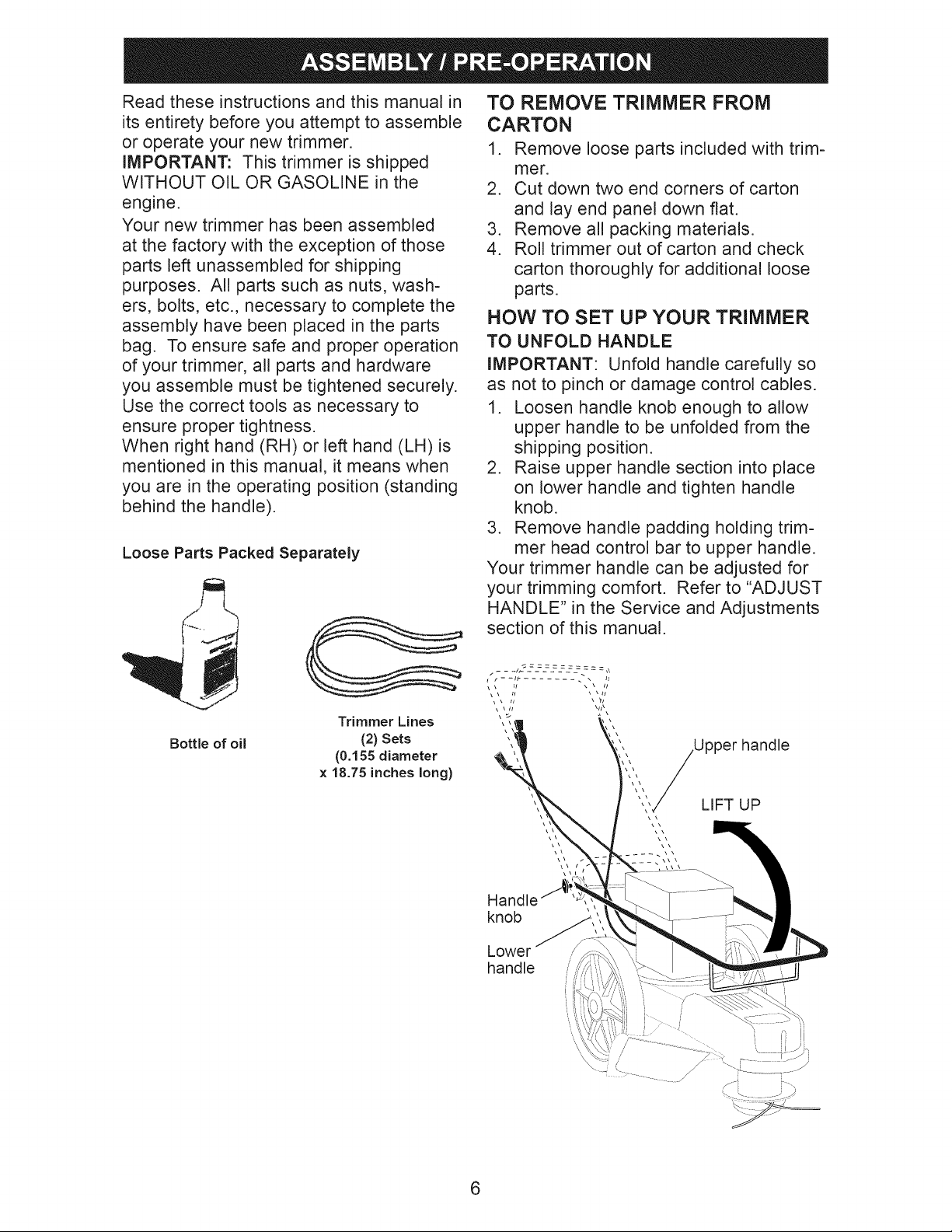
Loose Parts Packed Separately
TO REMOVE TRIMMER FROM
CARTON
1. Remove loose parts included with trim-
mer.
2. Cut down two end corners of carton
and lay end panel down flat.
3. Remove all packing materials.
4. Roll trimmer out of carton and check
carton thoroughly for additional loose
parts.
HOW TO SET UP YOUR TRIMMER
TO UNFOLD HANDLE
IMPORTANT: Unfold handle carefully so
as not to pinch or damage control cables.
1. Loosen handle knob enough to allow
upper handle to be unfolded from the
shipping position.
2. Raise upper handle section into place
on lower handle and tighten handle
knob.
3. Remove handle padding holding trim-
mer head control bar to upper handle.
Your trimmer handle can be adjusted for
your trimming comfort. Refer to "ADJUST
HANDLE" in the Service and Adjustments
section of this manual.
Bottle of oil
Trimmer Lines
(2) Sets
(0.155 diameter
× 18.75 inches long)
Upper handle
LIFT UP
\\
Handle
knob
Lower
handle
S --¸ [ ._
6
Page 7
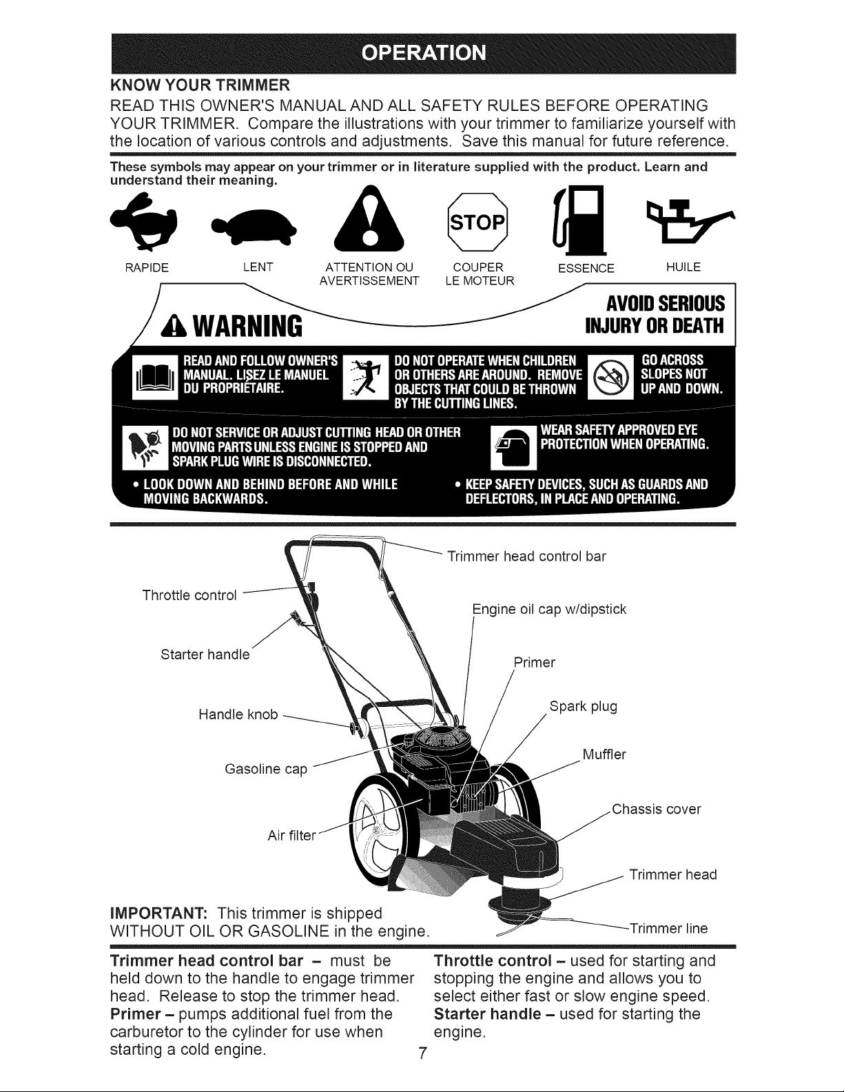
KNOWYOUR TRIMMER
READ THIS OWNER'S MANUAL AND ALL SAFETY RULES BEFORE OPERATING
YOUR TRIMMER. Compare the illustrations with your trimmer to familiarize yourself with
the location of various controls and adjustments. Save this manual for future reference.
These symbols may appear on your trimmer or in literature supplied with the product. Learn and
understand their meaning.
RAPIDE LENT ATTENTION OU
AVERTISSEMENT
• ,WAR
Throttle control
Starter handle
COUPER ESSENCE
LE MOTEUR
INJURYORDEATH
Trimmer head control bar
Engine oil cap w/dipstick
Primer
HUILE
AVOIDSERIOUS
Handle knob
Gasoline cap
Air
Spark plug
Muffler
cover
Trimmer head
IMPORTANT: This trimmer is shipped
WITHOUT OIL OR GASOLINE in the engine. -Trimmer line
Trimmer head control bar - must be
held down to the handle to engage trimmer
head. Release to stop the trimmer head.
Primer- pumps additional fuel from the
carburetor to the cylinder for use when
starting a cold engine.
Throttle control - used for starting and
stopping the engine and allows you to
select either fast or slow engine speed.
Starter handle - used for starting the
engine.
7
Page 8
The operationof any trimmercan resultin
foreignobjectsbeingthrown intothe eyes,
whichcan result in severeeye damage.
Alwayswear safetyglassesor eye shields
while operatingyour trimmer or performing
any adjustmentsor repairs. We recom-
mendstandard safetyglasses ora wide
visionsafety maskworn overspectacles.
HOW TO USE YOUR TRIMMER
ENGINE SPEED
The engine speed is controlled by a throt-
tle located on the side of the upper handle.
FAST position is for starting and normal
trimming. SLOW is for light trimming and
fuel economy. STOP is for stopping the
engine.
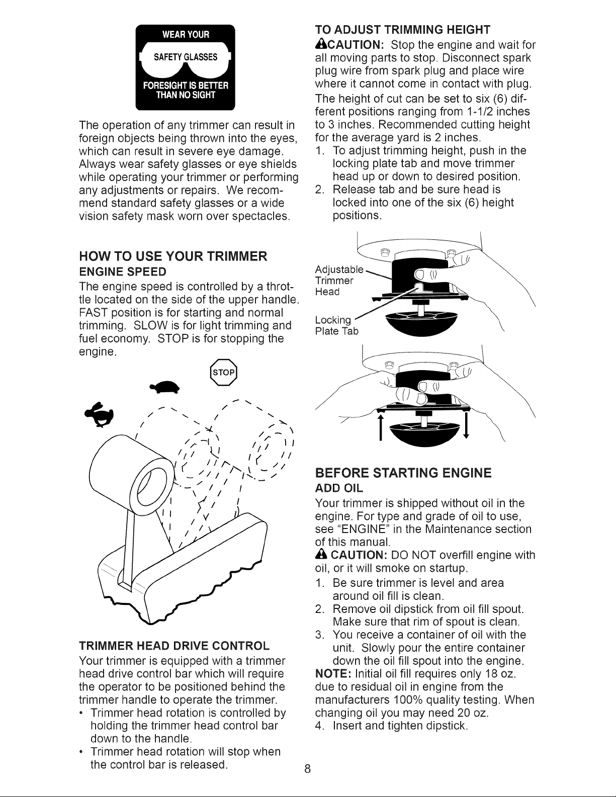
TOADJUST TRIMMINGHEIGHT
ACAUTION: Stop the engineand wait for
all movingpartsto stop. Disconnectspark
plugwirefrom spark plugand placewire
where it cannot come in contact with plug.
The height of cut can be set to six (6) dif-
ferent positions ranging from 1-1/2 inches
to 3 inches. Recommended cutting height
for the average yard is 2 inches.
1. To adjust trimming height, push in the
locking plate tab and move trimmer
head up or down to desired position.
2. Release tab and be sure head is
locked into one of the six (6) height
positions.
Adjustable
Trimmer
Head
Locking
Plate Tab
0
I
TRIMMER HEAD DRIVE CONTROL
Your trimmer is equipped with a trimmer
head drive control bar which wil! require
the operator to be positioned behind the
trimmer handle to operate the trimmer.
• Trimmer head rotation is controlled by
holding the trimmer head control bar
down to the handle.
• Trimmer head rotation will stop when
the control bar is released.
1 1
BEFORE STARTING ENGINE
ADD OIL
Your trimmer is shipped without oil in the
engine. For type and grade of oil to use,
see "ENGINE" in the Maintenance section
of this manual.
A CAUTION" DO NOT overfill engine with
oil, or it will smoke on startup.
1. Be sure trimmer is level and area
around oil fill is clean.
2. Remove oil dipstick from oil fill spout.
Make sure that rim of spout is clean.
3. You receive a container of oil with the
unit. Slowly pour the entire container
down the oil fill spout into the engine.
NOTE: Initial oil fil! requires only 18 oz.
due to residual oil in engine from the
manufacturers 100% quality testing. When
changing oil you may need 20 oz.
4. Insert and tighten dipstick.
8
Page 9
iMPORTANT:
• Check oil level before each use. Add oil
if needed. Fill to full line on dipstick.
• Change the oil after every 25 hours of
operation or each season. You may
need to change the oi! more often under
dusty, dirty conditions.
ADD GASOLINE
• Fill fuel tank to bottom of tank filler neck.
Do not overfill. Use fresh, clean, regular
unleaded gasoline with a minimum of 87
octane. Do not mix oil with gasoline. Pur-
chase fuel in quantities that can be used
within 30 days to assure fue! freshness.
,_ CAUTION: Alcohol blended fuels
(called gasohol or using ethanol or
methanol) can attract moisture which
leads to separation and formation of acids
during storage. Acidic gas can damage
the fue! system of an engine while in
storage. To avoid engine problems, the
fuel system should be emptied before
storage of 30 days or longer. Drain
the gas tank, start the engine and let it
run until the fuel lines and carburetor
are empty. Use fresh fuel next season.
See Storage Instructions for additional
information. Never use engine or
carburetor cleaner products in the fuel
tank or permanent damage may occur.
,_ CAUTION: Wipe off any spilled oil or
fuel. Do not store, spill or use gasoline
near an open flame.
Engine
oil cap
Gasoline
filler cap
TO STOP ENGINE
• To stop engine, move throttle control
lever to STOP position.
TO START ENGINE
1. Tostarta cold engine, push primerthree
(3) times before trying to start. Use a
firm push. This step is not usually neces-
sary when starting an engine which has
already run for a few minutes.
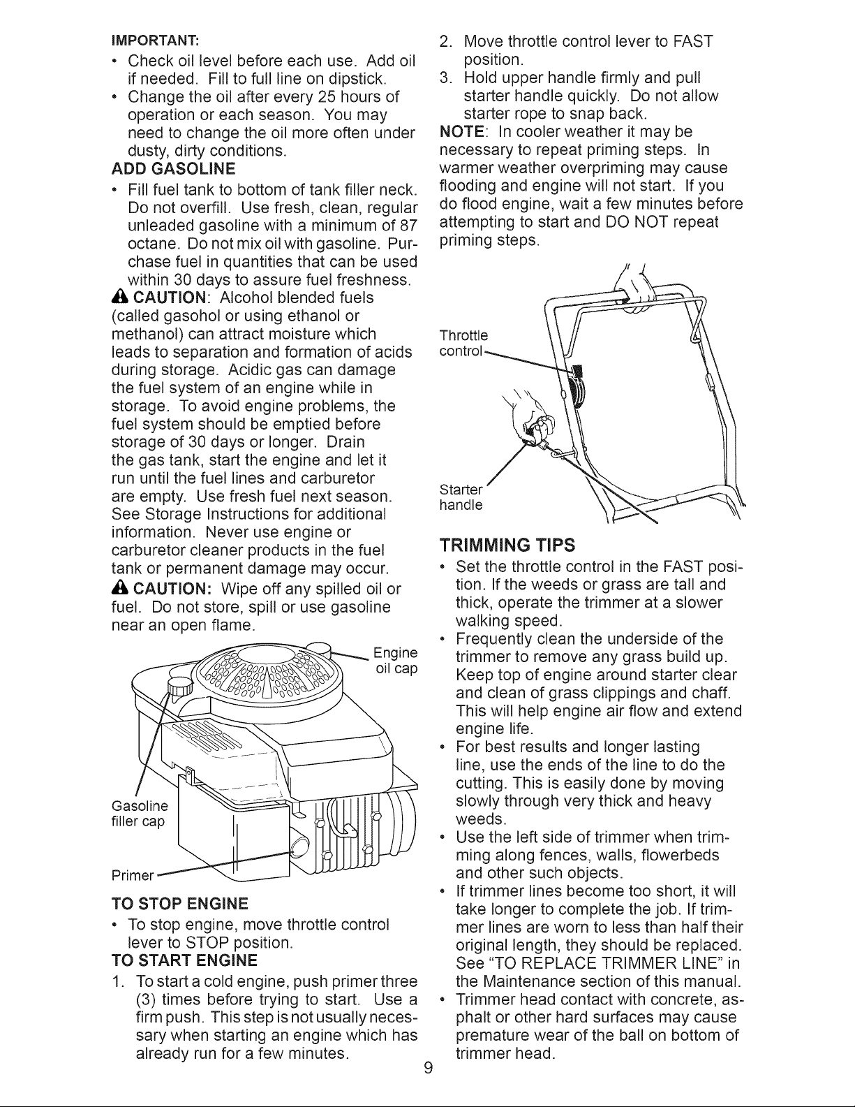
2. Move throttle control lever to FAST
position.
3. Hold upper handle firmly and pull
starter handle quickly. Do not allow
starter rope to snap back.
NOTE: In cooler weather it may be
necessary to repeat priming steps. In
warmer weather overpriming may cause
flooding and engine will not start. If you
do flood engine, wait a few minutes before
attempting to start and DO NOT repeat
priming steps.
Throttle
control__._ _ !\ !
Starter _ t
handle
TRIMMING TIPS
= Set the throttle control in the FAST posi-
tion. If the weeds or grass are tal! and
thick, operate the trimmer at a slower
walking speed.
• Frequently clean the underside of the
trimmer to remove any grass build up.
Keep top of engine around starter clear
and clean of grass clippings and chaff.
This will help engine air flow and extend
engine life.
• For best results and longer lasting
line, use the ends of the line to do the
cutting. This is easily done by moving
slowly through very thick and heavy
weeds.
• Use the left side of trimmer when trim-
ming along fences, walls, ftowerbeds
and other such objects.
• If trimmer lines become too short, it will
take longer to complete the job. If trim-
mer lines are worn to less than half their
original length, they should be replaced.
See "TO REPLACE TRIMMER LINE" in
the Maintenance section of this manual.
• Trimmer head contact with concrete, as-
phalt or other hard surfaces may cause
premature wear of the ball on bottom of
trimmer head.
9
Page 10

F,L',.OATES ......
AS YOU COMPLETE J_£,_:_£O_ERV/CE
REGULAR SERVICE f__-/_.." 4_ )_KT-"/_K_"¢ "I_ _r DATES
Check for Loose Fasteners If If
I_ Clean Trimmer I_ tf
_1 Clean Under Engine Cover tf2 tf
i_1 Check Drive Belt / Pulleys ll/'
I1_ Check / Replace Trimmer Lines 1#13
Check Engine Oil Level tf
Change Engine Oil lI_'1,2
Clean Air Filter tf 2
Inspect Muffler If
Clean or Replace Spark Plug i/
Replace Air Filter Paper Cartridge
1 - Change more often when operating under a heavy load or in high ambient temperatures.
2 - Service more often when operating in dirty or dusty conditions,
3 - Replace trimmer lines when they have worn to half their original length.
GENERAL RECOMMENDATIONS
The warranty on this trimmer does not cover
items that have been subjected to operator
abuse or negligence. To receive full value
from the warranty, operator must maintain
trimmer as instructed in this manual.
Some adjustments will need to be made
periodically to properly maintain your unit.
At least once a season, check to see if
you should make any of the adjustments
described in the Service and Adjustments
section of this manual.
• At least once a year, replace the spark
plug and replace air filter element. A
new spark plug and clean/new air filter
element assure proper air-fuel mixture
and help your engine run better and
last longer.
• Follow the maintenance schedule in
this manual.
BEFORE EACH USE
1. Check engine oil level.
2. Check for loose fasteners.
3. Clean under engine cover.
IMPORTANT: Do not oil or grease plastic
wheel bearings. Viscous lubricants will
attract dust and dirt that will shorten the
life of the self-lubricating bearings. If you
feel they must be lubricated, use only a dry,
powdered graphite type lubricant sparingly.
PRODUCT SPECIFICATIONS
Serial No.
Date of Purchase:
Gasoline Type:
Gasoline Capacity:
Oil Type:
(API-SF-SJ)
Oil Capacity:
Spark Plug: Champion RJ19LM
Trimmer Line Diameter:
Trimmer Line Length:
Unleaded Regular
1,5 Liters
SAE 30 (Above 32 ° F)
SAE 5W-30 (Below 32° F)
0,58 Liters
(Gap: 0,76 mm)
0,155 inch
18,75 inches
LUBRICATION
To prolong the useful life of your trimmer,
change engine oil as recommended in this
section of this Owner's Manual.
The model and serial numbers will be found
on a decal attached to the rear of the trim-
mer. Record both serial number and date of
10purchase in the space provided above.
Page 11

TRIMMER
Always observe safety rules when per-
forming any maintenance.
TIRES
, Keep tires free of gasoline, oil, or insect
control chemicals which can harm rub-
ber.
• Avoid stumps, stones, deep ruts, sharp
objects and other hazards that may
cause tire damage.
TRIMMER LINE
For best results, replace trimmer lines
when they have worn to half their original
length. Use .155 inch diameter trimmer
line. Cut new trimmer line length to 18-3/4
inches. After new line is installed on
trimmer head, check all lines so they do
not vary more then one (1) inch in length.
This is important to make sure the trim-
mer head is balanced and will not vibrate
abnormally.
_WARNING: Use onlythe specified trimmer
line. Do not use other materials such as wire,
string, rope, etc. Wire can break off during
trimming and become a dangerous missile
that can cause serious injury.
TO CUT LINE TO PROPER LENGTH
NOTE: Trimmer line pre-cut to proper
length is available for this unit; see the
Repair Parts section of this manual.
If trimmer line is purchased in bulk, it must
be cut to 18-3/4 inches before using. Use
the built-in length guage as follows:
1. From front of trimmer, place the end of
spooled trimmer line at the mark on the
side of the debris shield as shown.
2. Wrap trimmer line around front of chas-
sis cover to other side and cut at the
"22" mark (your unit's width of cut).
TO REPLACE TRIMMER LINE
1. Disconnect spark plug wire from spark
plug and place wire where it cannot
come in contact with plug.
2. Remove worn trimmer line from line
carrier plate.
3. Fold new, cutto length, trimmer line in half
and insert folded end through carrier plate
opening to back side of retainer clip.
4. With folded end of line at back side of
retainer clip, pull line outward until line
is fully seated under the retainer clip.
5. Repeat on other side of carrier plate.
6. Check all lines to be sure they are the
same length.
7. Reconnect spark plug wire to plug.
Trimmer
line
Carrier plate
opening
Chassis cover
WRAP
LINE
AROUND
Debris New
shield End of trimmer
mark spooled line line
Retainer clip
ENGINE
LUBRICATION
Use only high quality detergent oil rated
with API service classification SF-SJ.
Selectthe oil's SAE viscositygrade according
to your expected operating temperature.
SAE VISCOSITY GRADES
I _lvivl_[°: I
F -20 0 30 32 40 60 80 100
C -30 -2; -1; ; 1; 10 30 4;
TEMPERATURE RANGE ANTICIPATED BEFORE NEXT ©IL CHANGE
11
Page 12

NOTE: Although multi-viscosity oils (5W30,
10W30 etc.)improve starting in cold weather,
these multi-viscosity oils will result in in-
creased oil consumption when used above
32°F. Check your engine oil level more fre-
quently to avoid possible engine damage
from running low on oil.
Change the oil after every 25 hours of
operation or at least once a year if the unit
is not used for 25 hours in one year.
Check the crankcase oi! level before
starting the engine and after each five (5)
hours of continuous use. Tighten oil plug
securely each time you check the oil level.
TO CHANGE ENGINE OIL
NOTE: Before tipping trimmer to drain oil,
empty fuel tank by running engine until
fuel tank is empty.
1. Disconnect spark plug wire from spark
plug and place wire where it cannot
come in contact with plug.
2. Remove engine oil cap; lay aside on a
clean surface.
3. Tip trimmer on its side as shown and
drain oil into a suitable container. Rock
trimmer back and forth to remove any
oil trapped inside of engine.
3. Clean by gently tapping on a flat sur-
face. If very dirty, replace cartridge.
,I:;I,CAUTION: Petroleum solvents, such as
kerosene, are not to be used to clean car-
tridge. They ma y cause deterioration of the
cartridge. Do not oil cartridge. Do not use
pressurized air to clean or dry cartridge.
4. Install cartridge, then replace cover mak-
ing sure the tabs are aligned with the slots
in the back plate. Fasten screw securely.
Back plate
Cart_
MUFFLER
Inspect and replace corroded muffler as it
could create a fire hazard and/or damage.
SPARK PLUG
Replace spark plug at the beginning of
each mowing season or after every 100
hours of operation, whichever occurs
first. Spark plug type and gap setting
are shown in the "PRODUCT SPECIFIC-
ATIONS" section of this manual.
Container
4. Wipe off any spilled oil from trimmer or
side of engine.
5. Fil! engine with oil (See "ADD OIL" in
the Operation section of this manual).
6. Replace engine oil cap.
7. Reconnect spark plug wire to plug.
AIR FILTER
Your engine will not run properly and may
be damaged by using a dirty air filter.
Replace the air filter cartridge every 100
hours of operation or every season, which-
ever occurs first. Service air cleaner more
often under dusty conditions.
TO CLEAN AIR FILTER
1. Loosen screw and tilt cover to remove.
2. Carefully remove cartridge.
CLEANING
IMPORTANT: For best performance, keep
trimmer free of built-up grass and trash. Clean
the underside of your trimmer after each use.
_I:_,CAUTION: Disconnect spark plug wire
from spark plug and place wire where it
cannot come in contact with plug.
• Turn trimmer on its side. Make sure air
filter and carburetor are up. Clean the
underside of your trimmer by scraping to
remove build-up of grass and trash.
• Clean engine often to keep trash from
accumulating. A clogged engine runs
hotter and shortens engine life.
• Keep finished surfaces and wheels free
of all gasoline, oil, etc.
• We do not recommend using a garden
hose to clean trimmer unless the electrical
system, muffler, air filter and carburetor
are covered to keep water out. Water in
engine can result in shortened engine life.
12
Page 13

A WARNING: Toavoidserious injury, beforeperformingany serviceand adjustments:
1. Stop engine.
2. Makesurethe rotating lines and all movingpartshavecompletelystopped.
3. Disconnectspark plugwire fromspark plug and placewire where itcannotcome into
contactwith plug.
TRIMMER
TO ADJUST TRIMMING HEIGHT
See "TO ADJUST TRIMMING HEIGHT" in
the Operation section of this manual.
TO ADJUST HANDLE
The upper handle may be adjusted to dif-
ferent height positions.
1. Loosen handle knob only enough to
allow the upper handle to pivot to the
desired position.
2. Tighten handle knob securely.
NOTE: The handle knob and bolt may be
reversed for left handed operation.
Upper
handle
2. Lift cover up and away from trimmer.
3. Remove the two (2) screws on sides of
trimmer securing the debris shield.
4. Turn trimmer on its side with carburetor
and fuel cap up.
5. Remove the two (2) screws on under-
side of trimmer securing the debris
shield.
6. Slide the debris shield rearward and
remove.
7. Remove belt from engine pulley on
crankshaft.
Handle knob
TO REMOVE/REPLACE TRIMMER HEAD
DRIVE BELT
1. Remove screw at front of chassis
cover.
Screw
Chassis
cover
Engine
pulley
Debris shield screws
8. Remove belt from trimmer head pulley.
9. Note the position of the control cable
and idler return spring, then remove
idler assembly from chassis and re-
move belt and idler from trimmer.
10. Remove belt from idler assembly by
removing bottom belt keeper and idler
pulleys.
11.Assemble new belt, idler pulleys and
bottom belt keeper to idler bracket.
Tighten pulley bolts securely.
NOTE: Be sure belt is inside top belt
keeper on idler assembly.
12. Position belt and idler assembly in
trimmer, reconnect idler spring and as-
semble idler to chassis.
13. Install belt around trimmer head pulley
and engine pulley.
14. Replace debris shield and tighten the
four (4) screws securely.
15. Replace chassis cover and tighten
screw securely.
Always use Craftsman replacement parts
13to assure proper fit and long life.
Page 14

Engine pulley
Spacer
Nut
Idler bracket
Spacer \
Flat idler
,j
I
I
I
I
L
Control cable "
Belt
Idler assembly
Top belt keeper "
ENGINE
ENGINE SPEED
Bolt
Your engine speed has been factory set.
Do not attempt to increase engine speed
or it may result in personal injury. If you
believe that the engine is running too fast
or too slow, take your unit to a Sears or
other qualified service center for repair
and/or adjustment.
CARBURETOR
Your carburetor has a nonadjustable fixed
main jet for mixture control. If your engine
does not operate properly due to sus-
Idler
spring
Bottom
belt
keeper
Flat idler
Trimmer head pulley
pected carburetor problems, take your unit
to a Sears or other qualified service center
for repair and/or adjustment.
IMPORTANT: Never tamper with the
engine governor, which is factory set
for proper engine speed. Overspeeding
the engine above the factory high speed
setting can be dangerous. If you think
the engine-governed high speed needs
adjusting, take your unit to a Sears or
other qualified service center, which has
proper equipment and experience to make
any necessary adjustments.
Immediately prepare your trimmer for storage at the end of the season or if the unit will
not be used for 30 days or more.
TRIMMER
When trimmer is to be stored for a period
of time, clean it thoroughly, remove all dirt,
IMPORTANT: When folding the handle for
storage or transportation, be sure to fold
the handle as shown or you may damage
the control cables.
grease, leaves, etc. Store in a clean, dry area.
1. Clean entire trimmer (See "CLEANING" in
the Maintenance section of this manual).
2. Lubricate as shown in the Maintenance
section of this manual.
3. Be sure that all nuts, bolts, screws, and
pins are securely fastened. Inspect
Upper
handle
moving parts for damage, breakage
and wear. Replace if necessary.
4. Touch up all rusted or chipped paint
surfaces; sand lightly before painting.
Handle
knob
HANDLE
You can fold your trimmer handle for storage.
• Loosen handle knob enough to allow
upper handle to be folded forward. 14
Page 15

ENGINE
FUEL SYSTEM
iMPORTANT: it is important to prevent
gum deposits from forming in essential fuel
system parts such as carburetor, fuel filter,
fuel hose or tank during storage. Alcohol
blended fuels (called gasohol or using
ethanol or methanol) can attract moisture
which leads to separation and formation of
acids during storage. Acidic gas can damage
the fuel system of an engine while instorage.
, Empty the fuel tank by starting the en-
gine and letting it run until the fuel lines
and carburetor are empty.
, Never use engine or carburetor cleaner
products in the fue! tank or permanent
damage may occur.
, Use fresh fuel next season.
NOTE: Fuel stabilizer is an acceptable
alternative in minimizing the formation of fuel
gum deposits during storage. Add stabilizer
to gasoline in fuel tank or storage container.
Always follow the mix ratio found on stabilizer
container. Run engine at least 10 minutes
after adding stabilizer to allow the stabilizer
to reach the carburetor. Do not drain the gas
tank and carburetor if using fuel stabilizer.
ENGINE OIL
Drain oil (with engine warm) and replace
with clean engine oil. (See "ENGINE" in
the Maintenance section of this manual).
CYLINDER
1. Remove spark plug.
2. Pour one ounce (29 ml) of oil through
spark plug hole into cylinder.
3. Pul! starter handle slowly a few times
to distribute oil.
4. Replace with new spark plug.
OTHER
, Do not store gasoline from one season
to another.
• Replace your gasoline can if your can
starts to rust. Rust and/or dirt in your
gasoline will cause problems.
, if possible, store your unit indoors and
cover itto protect it from dust and dirt.
, Cover your unit with a suitable protective
cover that does not retain moisture. Do
not use plastic. Plastic cannot breathe,
which allows condensation to form and
will cause your unit to rust.
IMPORTANT: Never cover trimmer while
,_gine and exhaust areas are still warm.
CAUTION: Never store the trimmer
with gasoline in the tank inside a building
where fumes may reach an open flame
or spark. Allow the engine to cool before
storing in any enclosure.
15
Page 16

TROUBLESHOOTING =See appropriate section in manual unless directed
to a Sears Parts & Repair Centre.
PROBLEM
CAUSE
CORRECTION
Does not start
Loss of power
Excessive
Vibration
1. Dirty air filter.
2. Out of fue!.
3. Stale fuel.
4. Water in fuel.
5. Spark plug wire is
disconnected.
6. Bad spark plug.
7. Throttle control lever not
in correct position
(if equipped).
1. Dirty air filter.
2. Buildup of grass, leaves,
and trash under trimmer.
3. Too much oil in engine.
4. Walking speed too fast.
1. Lines uneven or broken.
2. Loose nuts or bolts.
3. Damaged trimmer head.
1. Clean/replace air filter.
2. Fill fuel tank.
3. Empty fuel tank and refill
with fresh, clean gasoline.
4. Empty fuel tank and refill
with fresh, clean gasoline.
5. Connect wire to spark plug.
6. Replace spark plug.
7. Move throttle lever to FAST
position.
1. Clean/replace air filter.
2. Clean underside of trimmer
and trimmer head.
3. Check oil level.
4. Trim at slower walking
speed.
1. Check trimmer lines.
2. Check all hardware,
including engine bolts.
3. Check/repair trimmer head.
Starter rope
hard to pull
1. Bent engine crankshaft.
1. Contact a Sears or other
qualified service centre.
Loss of head 1. Belt not driving. 1. Put belt on pulleys or
drive replace belt if broken.
Hard to push 1. Handle height position not 1. Adjust handle height
right for you. to suit.
1.
Poor trimming
performance
1. Trimmer line length is
too short.
If line is worn or broken to
half of original length,
replace line.
2. Throttle control lever not
in correct position
.
Move throttle lever to FAST
position.
(if equipped).
Trimmer head
does not
retain line
1. Trimmer line not
properly installed.
2. Broken line retainer clip.
1. Follow instructions in
Maintenance section.
2. Replace string carrier plate
assembly.
3. Incorrect size of
trimmer line.
3. Use .155 diameter
trimmer line.
16
Page 17

SERVICE NOTES
17
Page 18

CRAFTSMAN WEED TRIMMER - - MODEL NUMBER 944.361160
20
21
16 10
32
30
28
18
11
' _ 26
k
27
\
\
\
27
24
26
N
18
Page 19

CRAFTSMAN WEED TRIMMER == MODEL NUMBER 944.361160
KEY PART
NO. NO. DESCRiPTiON
1 === Engine, Briggs & Stratton, Model No.
126T02=1137-B1 (See Breakdown)
2 150406 Bolt, Engine Mounting 3/8=16
3 179466 Pulley, Engine
4 88348 Washer, Flat
8 169821X479 Handle, Lower
9 428867 Screw, Hex Washer Head 5/16=18 x 3/4
10 177815 Handle, Upper
11 170980 Bolt, Handle
12 189713X428 Knob, Handle
15 179751 Handle Adjuster Assembly
16 194788 Guide, Rope
18 66426 Wire Tire
19 176983 Control Bar
20 417238 Throttle Control
21 158755 Screw, Hex Washer Head
22 169787 Axle Shaft
23 428867 Screw, Hex Washer Head 5/16=18 x 3/4
24 169823 Spacer
25 197480 O=Ring
26 431880X460 Wheel, 12"x 1=3/4
27 409149 Locknut, Hex 3/8=16
28 181699 Drive Control Cable
29 178365 Decal, Warning
30 406678 Decal, Warning
31 172221X004 Support Bracket, Axle Shaft
32 164265 Grip, Handle
33 132004 Nut, Hex
34 429930X004 Bracket, Upstop
35 750634 Screw #10=24 x 5/8
36 851084 Bolt, Hex Head
37 850263 Washer, Lock
38 851074 Washer, Flat, Hardened
== 442829 Owner's Manual, English
== 422830 Owner's Manual, French
NOTE: All component dimensions given in U.S. inches. 1 inch = 25.4 mm.
IMPORTANT: Use only Original Equipment Manufacturer (O.E.M.) replacement parts.
Failureto do so could be hazardous, damage your weed trimmer and void your warranty.
19
Page 20

CRAFTSMAN WEED TRIMMER ==MODEL NUMBER 944.361160
52 51 20 47 21
,_ 14 \
-_ 43
i
17JJ__ _ 22
8 23
12 24
5 25
41 26
40 6 9 27*
4
45 19
7 28
10 _
13
29
27
o_ 31
3
32
33
34
46 _ 27 ----35
20
Page 21

CRAFTSMAN WEED TRIMMER ==MODEL NUMBER 944.361160
KEY PART
NO. NO. DESCRiPTiON
1 174031X615
2 182219
3 173715
4 185476
5 172145X004
6 166042
7 173716
8 73930600
9 166043
10 160829
11 73930500
12 173717
13 174719
14 409149
15 173811
16 180268
17 17060410
18 178848
19 199574
20 170553
21 149746
22 STD541137
23 STD551137
24 STD551037
25 180340
26 172551
27 174549
28 172520
29 169766X479
30 174543
31 174581
32 173973
33 172519
34 180338
35 182217
36 172516
37 174580
38 172523
39 180334
40 180333
41 174029
43 174042
45 174596X479
46 17060408
47 174510
51 189006
52 178848
Chassis Assembly
Line, Trimmer .155 diameter x 18.75 long
Screw, Self-Tapping 5/16-18 x 1
V-Belt
Bracket, idler
Pulley, idler, V-Groove
Bolt, Hex Head 3/8-16 x 1.25
Locknut, Hex 3/8-16
Pulley, idler, Flat
Bolt, Shoulder
Locknut 5/16-18
Spacer
Bolt, Shoulder
Locknut, Flange
Spring, Return
Deflector, Bottom
Screw 1/4-20 x 1/2
Screw #10-24 x 3/4
Belt Keeper
Cover, Chassis, Top
Screw #10-24 x 1-3/4
Nut, Hex 3/8-24 UNF
Washer, Lock 3/8
Washer, Flat 3/8
Pulley, Driven
Spacer, Pulley
Bearing
Jackshaft
Cover, Chassis, Bottom
Spindle Housing Assembly (* includes Upper Bearing, Key No. 27)
Ring, Retaining, External, 17mm
Spring, Locking Plate
Locking Plate
Carrier Plate Assembly
Mow Ball Assembly (includes Key Numbers 27, 37 and 38)
Cover, Bearing
Ring, Retaining, internal, 40mm
Mow Ball
Bolt, Mow Ball
Spindle Assembly, Complete (includes Key No. 22-28 and 30-39)
Spacer
Decal, instruction
Belt Keeper, Bottom
Screw, Self-Tapping
Decal, instruction
Deflector, Rear
Screw
NOTE: All component dimensions given in U.S. inches. 1 inch = 25.4 mm.
IMPORTANT:Use only Original Equipment Manufacturer (O.E.M.) replacement parts.
Failureto do so could be hazardous, damage your weed trimmer and void your warranty.
21
Page 22

BRIGGS & STRATTON 4-CYCLE ENGINE MODEL NUMBER 126T02=l137=B1
48 SHORT BLOCK
505 69
615 _
404 @ 306
616 i_ .... 307_
13U
5
[1058 OPERATOR'S MANUAL 1 11111329RE_I_I_II_GI_ i E1330 REPAIR MANUAL ]
3© 718ii
lO%;
11_._
f\,
40
847 ;;
358 ENGINE GASKET SET
20_
51_i _
163
524 ,.c_
585
\ y
32A
1095 VALVE GASKET SET
24i#
525
22
Page 23

BRIGGS & STRATTON 4-CYCLE ENGINE MODEL NUMBER 126T02-l137-B1
365 _'_
163
130
957A
617
190_
968
967
883
445 _
9661
_>_j_ I;_
__ I_
iq _J
11AQ_
443
3001
23
Page 24

BRIGGS & STRATTON 4-CYCLE ENGINE MODEL NUMBER 126T02=l137=B1
188_%
209 _ 202 _i_Z!_/ 333_
3347 851
621
55
65
592 @_'
356 //\\ ¢_ ""_-.-_
_b
362
332 '/_J
455
1005 _;,,____.=:-. ,j_f _,.
23
604
1211
58
1210
6O
459 U _/
689 _,;_
456
I 1036 EMISSIONS LABEL I
597 _
/
/
37
78 _
Engine Power Rating Information
The gross power rating for individual gas engine models is labeled in accordance with SAE (So-
ciety of Automo-tive Engineers) code J11940 (Small Engine Power & Torque Rating Procedure),
and rating performance has been obtained and corrected in accordance with SAE J1995 (Revision
2002-5). Actual gross engine power will be lower and is affected by, among other things, ambi-
ent operating conditions and engine-to-engine variability. Given both the wide array of products
on which engines are placed and the variety of environmental issues applicable to operating the
equipment, the gas engine will not develop the rated gross power when used in a given piece of
power equipment (actual "on-site" or net horsepower). This difference is due to a variety of factors
including, but not limited to, accessories (air cleaner, exhaust, charging, cooling, carburetor, fuel
pump, etc.), application limitations, ambient operating conditions (temperature, humidity, altitude),
and engine-to-engine variability. Due to manufacturing and capacity limitations, Briggs & Stratton
may substitute an engine of higher rated power for this Series engine.
24
Page 25

BRIGGS & STRATTON 4-CYCLE ENGINE MODEL NUMBER 126T02=l137=B1
KEY PART KEY PART
NO. NO. DESCRIPTION NO. NO. DESCRIPTION
1 697322 Cylinder Assembly 28 298909 Pin=Piston
2 399269 Bushing / Seal Kit (Used After Code Date
(Magneto Side) 09041600).
3 * 299819s Seal=Oil (Magneto Side) 499423 Pin=Piston (Used Before
4 493279 Sump=Engine Code Date 09041700).
5 691160 Head=Cylinder 29 797306 Rod=Connecting (Used After
7 *, 692249 Gasket=Cylinder Head Code Date 09041600).
8 695250 Breather Assembly 499424 Rod=Connecting
9 *_ 699472 Gasket=Breather (Used Before Code Date
10 691125 Screw (Breather Assembly) 09041700).
11 691781 Tube=Breather 32 691664 Screw (Connecting Rod)
11A 691923 Tube=Breather (Short)
(Air Cleaner Primer Base) 32A 695759 Screw (Connecting Rod)
12 * 692232 Gasket=Crankcase (Long)
13 690912 Screw (Cylinder Head) 33 262651s Valve=Exhaust
15 691680 Plug=Oil Drain 34 262652s Valve=intake
16 691451 Crankshaft 35 691270 Spring=Valve (intake)
20 * 391781s Seal=Oil (PTO Side) 36 691270 Spring=Valve (Exhaust)
22 691092 Screw 37 793756 Guard=Flywheel
(Crankcase Cover / Sump) 40 692194 Retainer=Valve
23 790536 Flywheel 43 697799 Slinger=Governor / Oil
24 222698s Key=Flywheel 45 690548 Tappet=Valve
25 797302 Piston Assembly (Standard 46 691449 Gear=Cam
Size) (Used After Code 48 792738 Short Block
Date 09041600). 50 794305 Manifold=intake
795429 Piston Assembly (Standard 51 * 794306 Gasket=intake
Size) (Used Before Code 54 691650 Screw (intake Manifold)
Date 09041700). 55 697670 Housing=Rewind Starter
797303 Piston Assembly (.020" 58 697316 Rope=Starter (Cut to Fit)
Oversize) (Used After Code 60 281434s Grip=Starter Rope
Date 09041600). 65 690837 Screw (Rewind Starter)
795430 Piston Assembly (.020" 78 691108 Screw (Flywheel Guard)
Oversize) (Used Before 81 691740 Lock-Muffler Screw
Code Date 09041700). 97 696565 Shaft-Throttle
26 797304 Ring Set (Standard Size) 104 ,_ 691242 Pin-Float Hinge
(Used After Code Date 117 498978 Jet=Main (Standard Size)
09041600). 118 497466 Jet=Main (High Altitude)
795431 Ring Set (Standard Size) 121 498260 Kit-Carburetor Overhaul
(Used Before Code Date 125 498170 Carburetor (Primer System)
09041700). 127 694468 Plug=Welch
797305 Ring Set (.020" Oversize) 130 696564 Valve-Throttle
(Used After Code Date 133 398187 Float=Carburetor
09041600). 134 398188 Kit=Needle / Seat
795432 Ring Set (.020" Oversize) 137 ,_ 693981 Gasket=Float Bowl
(Used Before Code Date 163 • 795629 Gasket=Air Cleaner
09041700). 177 • 691031 SeaI-O Ring (Dipstick)
27 691588 Lock-Piston Pin (Used After 187 791766 Line=Fuel
Code Date 09041600). (Cut to Required Length)
691866 Lock=Piston Pin 188 693399 Screw (Control Bracket)
(Used Before Code Date 190 690940 Screw (Fuel Tank)
09041700). 202 691829 Link-Mechanical Governor
25
Page 26

BRIGGS & STRATTON 4-CYCLE ENGINE MODEL NUMBER 126T02=l137=B1
KEY PART KEY PART
NO. NO. DESCRIPTION NO. NO. DESCRIPTION
209 691291 Spring-Governor 689 691855 Spring-F riction
(Vermillion / Red) 703 696309 Clip (Debris Shield)
222 790143 Bracket-Control (Remote / 718 690959 Pin-Locating
Manual Friction) (Primer) 741 790345 Gear-Timing
227 690783 Lever-Governor Control 847 692047 Dipstick / Tube Assembly
276 ,_ 271716 Washer-Sealing 851 692424 Terminal-Spark Plug
287 690940 Screw (Dipstick Tube) 868 697338 Seal-Valve
300 692038 Muffler 869 691155 Seat-Valve (Intake)
304 493294 Housing-Blower 870 690380 Seat-Valve (Exhaust)
305 691108 Screw (Blower Housing) 871 262001 Bushing-Guide (Exhaust)
306 690450 Shield-Cylinder 871 63709 Bushing-Valve Guide
307 690345 Screw (Cylinder Shield) (Intake)
332 690662 Nut (Flywheel) 883 *_ 691881 Gasket-Exhaust
333 793353 Armature-Magneto 949 696306 Guard-Debris Screen
334 691061 Screw (Magneto Armature) 957 796654 Cap-Fuel Tank
337 796112s Plug-Spark 957A 793606 Cap-Fuel Tank (Fuel Fresh)
356 692390 Wire-Stop 966 795259 Base-Air Cleaner Primer
358 794307 Gasket Set-Engine 967 493437s Filter-Pre Cleaner
362 793351 Shield-Spark Plug 968 692298 Cover-Air Cleaner
365 691688 Screw (Carburetor) 972 699374 Tank-Fuel
404 690272 Washer (Governor Crank) 975 493640 Bowl-Float
425 690670 Screw (Air Cleaner Cover) 976 694395 Primer-Carburetor
443 692523 Screw (Air Cleaner Base) 997 696310 Shield-Debris
445 491588s Filter-Air Cleaner Cartridge) 1036 - - - Label-Emissions (Available
455 791960 Cup-Flywheel from any Briggs & Stratton
456 692299 Retainer-Spring Authorized Dealer)
459 281505s PawI-Ratchet 1058 277039 Operator's Manual
505 691251 Nut (Governor Lever) 1059 692311 Kit-Screw / Washer
523 499621 Dipstick (Fuel Tank)
524 * 692296 Seal-Dipstick Tube 1095 498528 Gasket Set-Valve
525 495265 Tube-Dipstick 1210 498144 Pulley / Spring Assembly
562 691119 Screw (Governor Lever) (Pulley)
563 691138 Screw (Debris Screen) 1211 498144 Pulley / Spring Assembly
564 690351 Screw (Control Cover) (Spring)
584 697734 Cover-Breather Passage 1329 126T02-0010-B1 Replacement Engine
585 • 691879 Gasket-Breather Passage (Replacement engine listed
592 690800 Nut (Rewind Starter) is not available in the State
597 691696 Screw (Ratchet Pawl) of California. Repair with
601 791850 Clamp-Hose individual parts.)
604 691757 Cover-Control 1330 270962 Repair Manual
608 697671 Starter-Rewind - - 398067 Spark Arrester
613 691340 Screw (Muffler) (available accessory)
615 690340 Retainer-Governor Shaft
616 698801 Crank-Governor • Engine Gasket Set, Key Number 358
617 270344s O Ring (Intake Manifold)
621 692310 Switch-Stop _ Valve Gasket Set, Key Number 1095
633 ,_ 691321 Seal-Choke / Throttle Shaft
668 • 493823 Spacer (Control Bracket) ,_ Carburetor Overhaul Kit, Key Number 121
676 393760 Deflector-Muffler
677 690661 Screw (Muffler Deflector) NOTE: All component dimensions given in U.S.
684 690345 Screw (Breather Cover) inches. 1 inch = 25.4 mm
26
Page 27

Operate a trimmer across the face
of slopes, never up or down slopes.
10 DEGREES
15 DEGREES
Use this guide and do not trim on a slope greater than 15 degrees.
A 10 degree slope is a hill that increases in height at approximately 1.7 feet in 10 feet.
A 15 degree slope Is a hill that increases in height at approximately 2.5 feet tn 10 feet.
Use extreme care at alt times and avoid sudden turns or maneuvers. Follow other instructions in this
manual for safety in trimming on slopes. Operate a trimmer across the face of slopes, never up or down
slopes. Use extra care when operating on or near slopes and obstructions.
Page 28

Just Call:
1-800-4-MY-HOME ®
(1-800-469-4663)
24 hours a day, 7 days a week
For the repair of major brand appliances in your own home...
no matter who made it, no matter who sold it!
For your nearest Sears Parts and Service location,
to bring in products like vacuums, lawn equipment and electronics.
For Sears Parts & Service, to order the replacement parts,
accessories and owner's manuals that you need to do-it-yourself.
www.sears.ca
To purchase or inquire about a Sears Maintenance Agreement, call:
1-800-361-6665
9 a.m.-11 p.m. Mon.- Fri., EST, 9 a.m.- 4 p.m. Sat.
Pour service en fran?ais: i
1-800-LE-FOYER Mc
(1-800-533-6937)
www,sears,ca
(_)/TM Trademarks of Sears, Roebuck and Co. used under license bySears Canada
MDMarquedeposee / MCMarque de commerce de Sears, Roebuck and Co. utilisee en vertu d'une licence de Sears Canada
442829 03.02.11 BY Printed in U.S.A.
 Loading...