

Craftsman 929993 Owner's Manual
Owner's Manual
II:RRFTSMRN'I
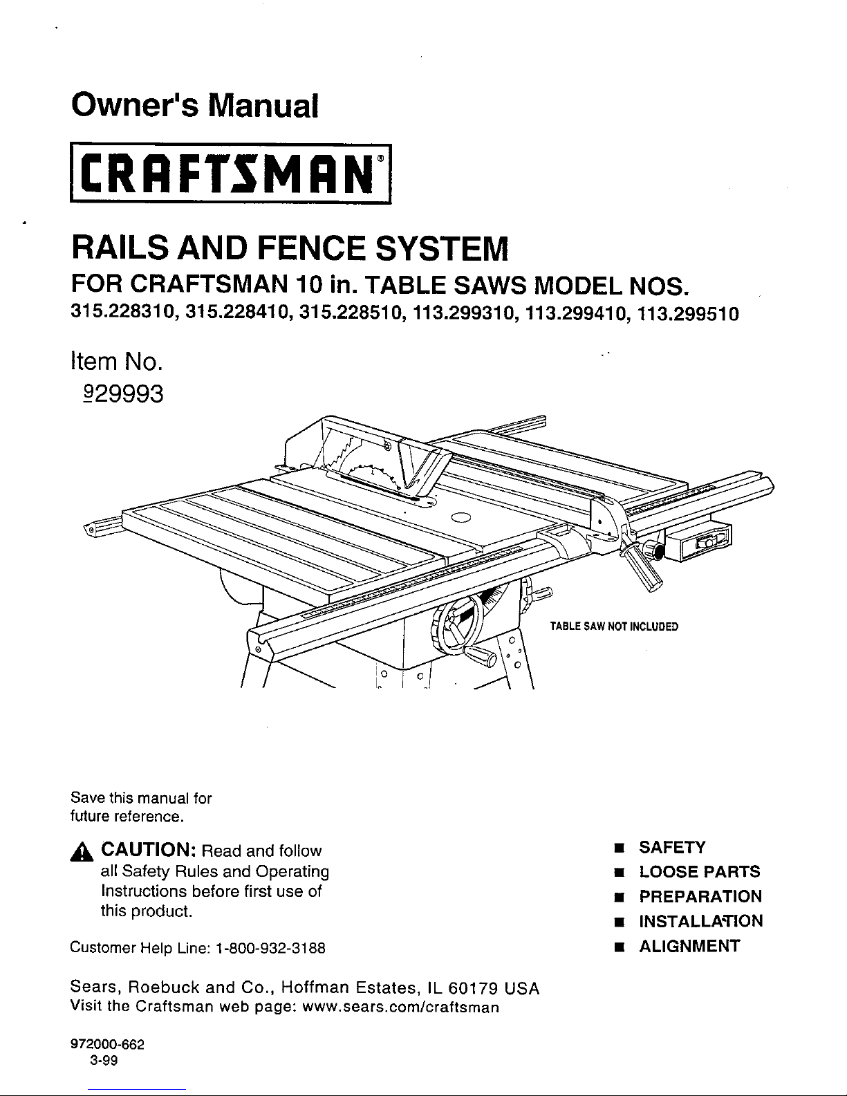
RAILS AND FENCE SYSTEM
FOR CRAFTSMAN 10 in. TABLE SAWS MODEL NOS.
315.228310, 315.228410, 315.228510, 113.299310, 113.299410, 113.299510
Item No.
_929993
TABLE SAWNOTINCLUDED
Save this manual for
future reference.
_, CAUTION: Read and follow
all Safety Rules and Operating
Instructions before first use of
this product.
Customer Help Line: 1-800-932-3188
Sears, Roebuck and Co., Hoffman Estates, IL 60179 USA
Visit the Craftsman web page: www.sears.com/craftsman
972000-662
3-99
• SAFETY
• LOOSE PARTS
• PREPARATION
• INSTALLATION
• ALIGNMENT
READ ALL INSTRUCTIONS
• READ THESE INSTRUCTIONS AND THE
INSTRUCTIONS FOR YOUR TABLE SAW
THOROUGHLY before using accessories.
KNOW YOUR POWER TOOL. Read the owner's
manual for the Table Saw carefully. Learn the
saw's applications and limitations as well as the
specific potential hazards related to this tool.
KEEP THE WORK AREA CLEAN. Cluttered
work areas and work benches invite accidents.
DO NOT leave tools or pieces of wood on the
saw while it is in operation.
• ALWAYS WEAR SAFETY GLASSES. Everyday
eyeglasses have only impact-resistant lenses;
they are NOT safety glasses.
• ALWAYS DISCONNECT SAW FROM POWER
SUPPLY BEFORE MAKING ADJUSTMENTS
OR ADDING ACCESSORIES. Make sure the
switch is off when reconnecting to power supply,
• SAVE THESE INSTRUCTIONS. Refer to them
frequently and use to instruct other users. If you
loan someone this tool, loan them these instruc-
tions also.
Look for this symbol to point out important safety precautions. It
means attention.q! Your safety is involved.
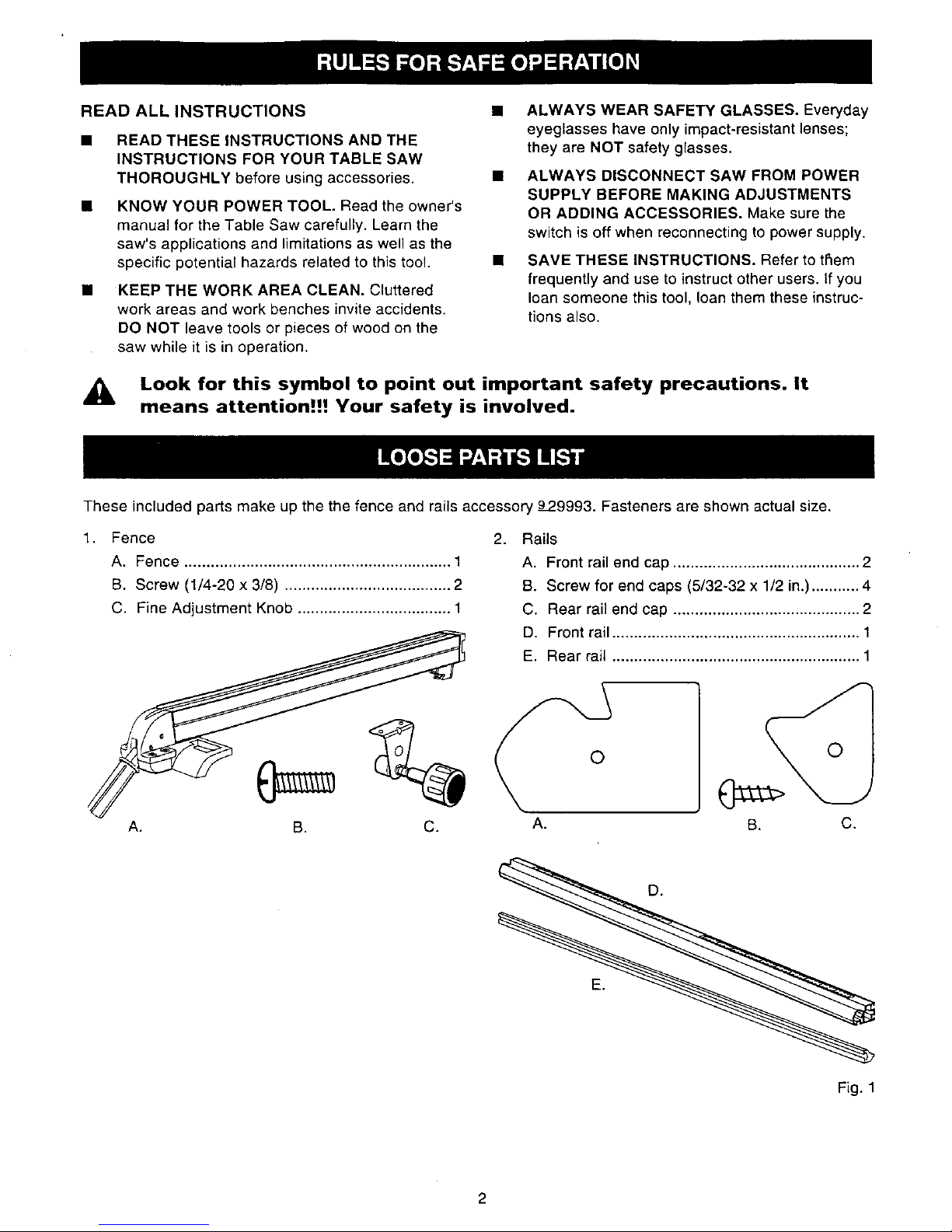
These included parts make up the the fence and rails accessory 9P9993. Fasteners are shown actual size.
1. Fence
A, Fence ............................................................. 1
B. Screw (1/4-20 x 3/8) ...................................... 2
C. Fine Adjustment Knob ................................... 1
A. B. C.
2.
Rails
A. Front rail end cap ........................................... 2
B. Screw for end caps (5/32-32 x 1/2 in.) ........... 4
C, Rear rail end cap ........................................... 2
D. Front rail ......................................................... 1
E. Rear rail ......................................................... 1
O
©
B.
A. C.
Fig. 1
2
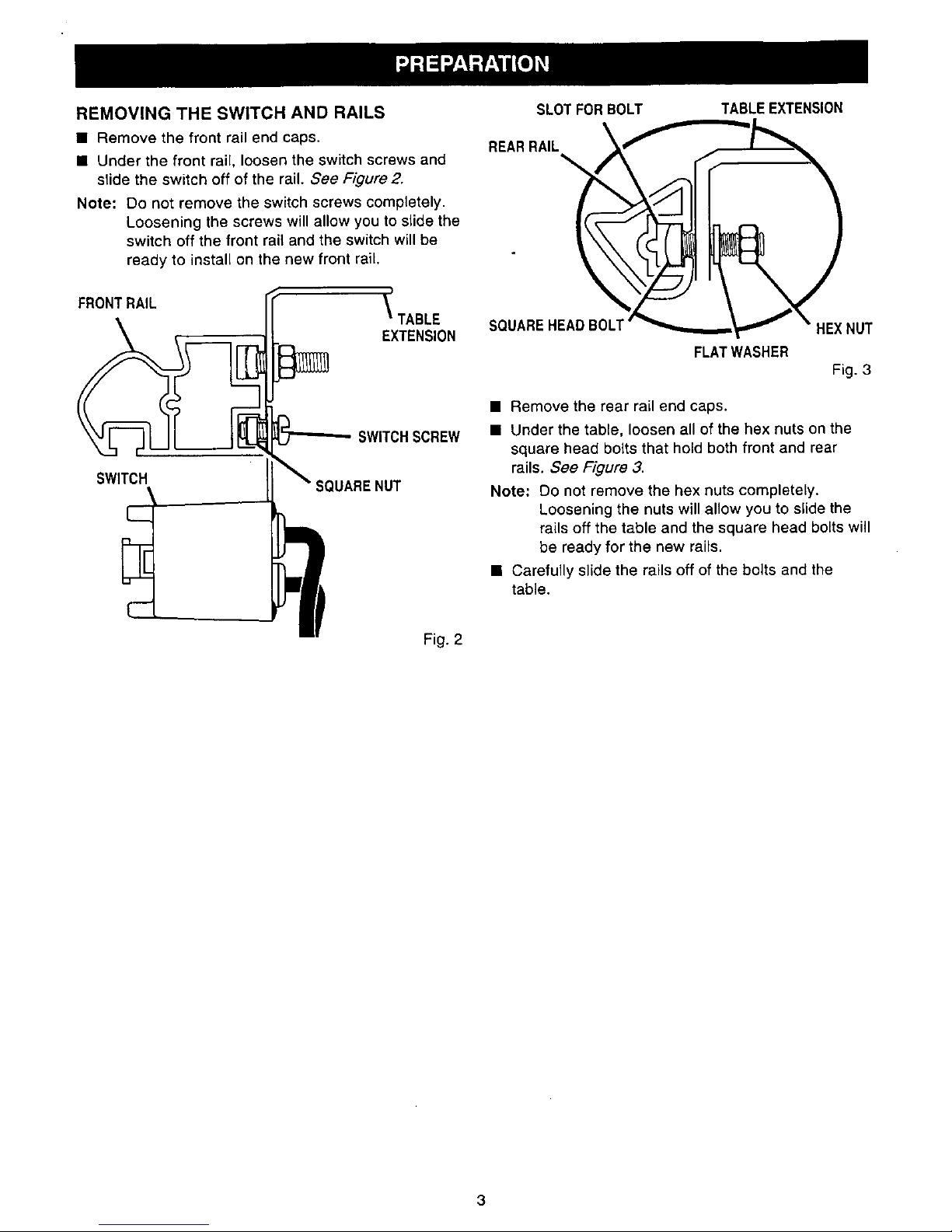
REMOVING THE SWITCH AND RAILS
• Remove the front rail end caps.
• Under the front rail, loosen the switch screws and
slide the switch off of the rail. See Figure 2.
Note: Do not remove the switch screws completely.
Loosening the screws will allow you to slide the
switch off the front rail and the switch will be
ready to install on the new front rail,
FRONTRAIL
_ TABLE
EXTENSION
SWITCH
L._
SWlTCHSCREW
SQUARENUT
Fig. 2
SLOTFORBOLT
REARRAIL __
SQUAREHEADBOLT
TABLEEXTENSION
HEXNUT
FLATWASHER
Fig. 3
• Remove the rear rail end caps.
• Under the table, loosen all of the hex nuts on the
square head bolts that hold both front and rear
rails. See Figure 3.
Note: Do not remove the hex nuts completely.
Loosening the nuts will allow you to slide the
rails off the table and the square head bolts will
be ready for the new rails.
• Carefully slide the rails off of the bolts and the
table.
 Loading...