

Craftsman 921169530 Owner’s Manual
Operator’s Manual
®
AIR COMPRESSOR
3-gallon
1/3 HP
Oil-Free
Universal Motor and Pump
Model No. 16953
CAUTION:
Before using this product,
read this manual and follow
all its Safety Rules and
Operating Instructions.
Sears Brands Management Corporation
Hoffman Estates, IL 60179 U.S.A.
www.craftsman.com
02/19/2016
Part No. E109568
• Safety Instructions
• Installation & Operation
• Maintenance & Storage
• Troubleshooting Guide
• Parts List
• Español

Table of Contents
Page
Warranty.......................................................
Safety Symbols ................................................... 1
Important Safety Instructions & Guidelines .............................. 1
Specifications..................................................... 2
Glossary ......................................................... 2
Duty Cycle ....................................................... 2
Parts & Features................................................... 3
Installation & Assembly ............................................. 4
Operating Procedures .............................................. 5
Maintenance...................................................... 6
Storage .......................................................... 6
Troubleshooting Guide .............................................. 7
See Below
Exploded View .................................................... 8
Parts List ........................................................ 9
Español.......................................................... 11
CRAFTSMAN LIMITED WARRANTY
FOR ONE YEAR from the date of sale this product is warranted against defects in
material or workmanship.
WITH PROOF OF SALE a defective product will be replaced free of charge.
For warranty coverage details to receive free replacement, visit the web page:
www.craftsman.com/warranty.
This ONE YEAR warranty is void if this product is ever used while providing
commercial services or if rented to another person. For 90 DAY commercial and rental
use terms, see the Craftsman warranty web page.
This warranty gives you specific legal rights, and you may also have other rights which
vary from state to state.
Sears Brands Management Corporation,
Hoffman Estates, IL 60179 U.S.A.
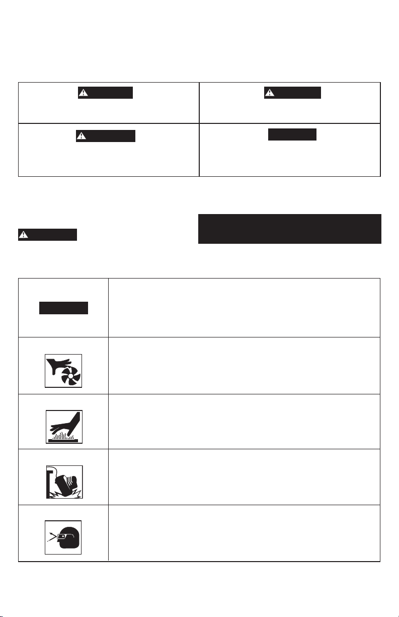
Safety Symbols
The information listed below should be read and understood by the operator. This information is given to protect the
user while operating and storing the air compressor. We utilize the symbols below to allow the reader to recognize
important information about their safety.
DANGER
Indicates an imminently hazardous situation which,
if not avoided, will result in death or serious injury.
WARNING
Indicates a potentially hazardous situation which, if
not avoided, could result in death or serious injury
Indicates a potentially hazardous situation which, if
not avoided, may result in minor or moderate injury.
When used without the safety alert symbol indicates
a potentially hazardous situation which, if not
avoided, may result in property damage.
CAUTION
CAUTION
Important Safety Instructions and Guidelines
• Save all instructions
WARNING
Improper operation or maintenance of this product could result in serious injury and/or property damage. Read and
understand all of the warnings and safety instructions provided before using this equipment.
The air compressor should be operated on a dedicated 15 amp circuit. If the
circuit does not have 15 free amps available, a larger circuit must be used.
CAUTION
Risk of Moving Parts
Always use more air hose before utilizing extension cords. All extension cords
used must be 12 gauge with a maximum length of 25 ft. The circuit fuse type
must be a time delay. Low voltage could cause damage to the motor.
If the air compressor is in operation, all guards and covers should be
attached or installed correctly. If any guard or cover has been damaged, do
not operate the equipment until the proper personnel has correctly repaired
the equipment. The power cord should be free of any moving parts, twisting
and/or crimping while in use and while in storage.
WARNING: This product contains one or more chemicals known to the
State of California to cause cancer and birth defects or other reproduc
tive harm. Wash hands after handling.
-
Risk of Burns
Risk of Falling
Risk from Flying Objects
There are surfaces on your air compressor that while in operation and
thereafter can cause serious burns if touched. The equipment should be
allowed time to cool before any maintenance is attempted. Items such as the
compressor pump and the outlet tube are normally hot during and
after operation.
Operation of the air compressor should always be in a position that is stable.
Never use the air compressor on a rooftop or elevated position that could
allow the unit to fall or be tipped over. Use additional air hose for
elevated jobs.
Always wear ANSI Z87.1 approved safety glasses with side shields when the
air compressor is in use. Turn off the air compressor and drain the air tank
before performing any type of maintenance or disassembly of the hoses or
fittings. Never point any nozzle or sprayer toward any part of the body or at
other people or animals.
1
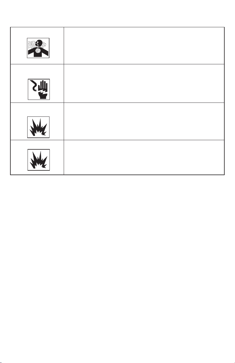
Important Safety Instructions & Guidelines
Risk of Breathing
Risk of
Electrical Shock
Avoid using the air compressor in confined areas. Always have adequate
space (12 in.) on all sides of the air compressor. Also keep children, pets,
and others out of the area of operation. This air compressor does not provide
breathable air for anyone or any auxiliary breathing device. Spraying material
will always need to be in another area away from the air compressor to not
allow intake air to damage the air compressor filter.
Never utilize the air compressor in the rain or wet conditions. Any electrical
issues or repairs should be performed by authorized personnel such as an
electrician and should comply with all national and local electrical codes.
The air compressor should also have the proper three prong grounding plug,
correct voltage, and adequate fuse protection.
Risk of
Explosion or Fire
Risk of Bursting
Never operate the compressor near combustible materials, gasoline or
solvent vapors. If spraying flammable materials, locate the air compressor
at least 20 ft. away from the spray area. Never operate the air compressor
indoors or in a confined area.
Always drain the air compressor tank daily or after each use. If the tank
develops a leak, then replace the air compressor. Never use the air compressor
after a leak has been found or try to make any modifications to the tank.
Never modify the air compressor’s factory settings which control the tank
pressure or any other function.
Specifications
Pump ...............................Oil-Free
Motor .......................1/3 HP (Universal)
Bore ................................0.98 in.
Stroke............................... 0.67 in.
Voltage Single Phase . . . . . . . . . . . . . . . . . . 120 VAC
Minimum Circuit Requirement . . . . . . . . . . 2.9 Amps
Glossary
CFM: Cubic feet per minute.
SCFM: Standard cubic feet per minute;
a unit of measure for air delivery.
PSIG: Pounds per square inch gauge;
a unit of measure for pressure.
ASME: American Society of Mechanical Engineers.
California Code: Unit complies with
California Code 462 (l) (2)/ (M) (2).
Air Tank Capacity .....................3 Gallons
Cut-in Pressure ........................70 PSI
Cut-out Pressure ......................100 PSI
SCFM @ 90 PSI . . . . . . . . . . . . . . . . . . . . . . . . . . .0.4
Cut-In Pressure: The air compressor will
automatically start to refill the tank
when the pressure drops below the
prescribed minimum.
Cut-Out Pressure: The point at which the
motor stops when the tank has reached
maximum air pressure.
Code Certification: Products that bear one or
more of the following marks: UL, ULc, ETL,
CSA, have been evaluated by OSHA-certified
independent safety laboratories and meet the
applicable Underwriters Laboratories
Standards for Safety.
Duty Cycle
This is a 50% duty cycle air compressor. Do not run the air compressor for a combined total of more than
30 minutes in the space of one hour.
2
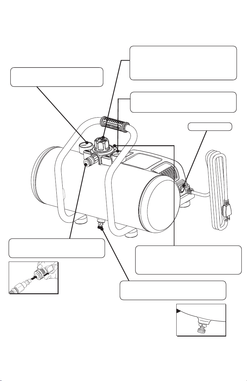
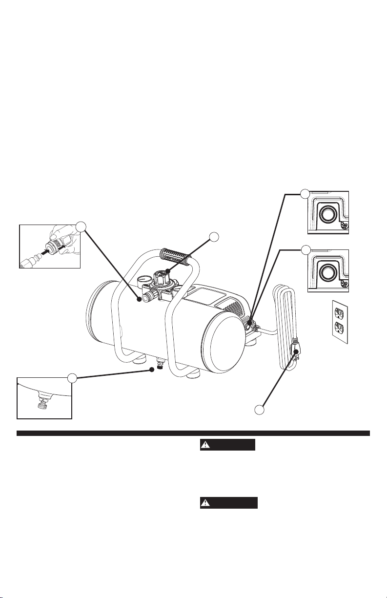
Parts & Features
See figures below for reference.
Tank Pressure Gauge
Indicates the reserve air pressure
in the tank.
Regulator
The air pressure coming from the air tank is
controlled by the regulator. To increase the
pressure turn the knob clockwise and to
decrease the pressure turn the
knob counterclockwise.
Regulator Gauge
Indicates the outgoing air pressure to the tool
and is controlled by the regulator.
ON/OFF Switch
Quick Connect
Offers a quick release feature for attaching
and removing the air hose.
Tank Safety Valve
Used to allow excess tank pressure to escape
into the atmosphere. This valve should only open
when the tank pressure is above the
maximum rated pressure.
Tank Drain Valve
Used to drain condensation from the air tank.
Located at bottom of tank.
3

Installation & Assembly
WARNING
The air compressor should be turned off, unplugged
from the power source, the air bled from the tank
and the unit allowed time to cool before any
maintenance is performed. Personal injuries could
occur from moving parts, electrical sources,
compressed air or hot surfaces. The quick connect
assembly must be attached before use. Failure to
assemble correctly could result in leaks and possible
injury. If unsure of assembly instructions or you
experience difficulty in assembly, take the unit to a
qualified service dealer for assistance.
Do not modify the plug provided. If it will not fit the
outlet, have the proper outlet installed by a
qualified electrician.
WARNING
This product is for use on a circuit having a nominal
rating of 120 volts and is factory-equipped with a
specific electric cord and plug to permit connection
to a proper electric circuit.
Getting Started - Location of the Air Compressor
The air compressor should always be located in a
clean, dry and well ventilated environment. The unit
should have at minimum, 12 in. of space on
each side.
WARNING
Risk Of Fire Or Explosion
This product incorporates snap action switch
contacts and a universal electric motor which tend
to produce arcs and sparking and therefore should
not be exposed to flammable liquids or vapors.
This product is not intended for installation or use in
a commercial garage or shop environment.
Grounding Instructions
This product should be grounded. In the event of an
electrical short circuit, grounding reduces the risk of
electric shock by providing an escape wire for the
electric current.
This product is equipped with a cord having a
grounding wire with an appropriate grounding plug.
(See the figure at top right corner.) The plug must
be plugged into an outlet that is properly installed
and grounded in accordance with all local codes
and ordinances. Check with a qualified electrician
or service personnel if these instructions are not
completely understood or if in doubt as to whether
the tool is properly grounded.
Improper installation of the grounding plug will result
in a risk of electric shock. If repair or replacement
of the cord or plug is necessary, do not connect
the grounding wire to either flat blade terminal. The
wire with insulation having an outer surface that is
green with or without yellow stripes is the grounding
wire. Check with a qualified electrician or service
personnel if the grounding instructions are not
completely understood, or if in doubt as to whether
this product is properly grounded.
Plug
Grounded
Outlet
Grounding Pin
Make sure the product is connected to an outlet
having the same configuration as the plug.
An adapter should not be used with this product.
If the product must be reconnected for use on a
different type of electric circuit, qualified service
personnel should make the reconnection.
Extension Cords
Use only a 3-wire extension cord that has a 3-blade
grounding plug and a 3-slot receptacle that will
accept the plug on the product. Make sure your
extension cord is in good condition. When using an
extension cord, be sure to use one heavy enough to
carry the current your product will draw. Cords must
not exceed 25 ft. and No. 12 AWG size must be
used. An undersized cord will cause a drop in line
voltage resulting in loss of power and overheating.
Break In Procedures
No break in procedure is required by the user.
This product is factory tested to ensure proper
operation and performance.
4
Operating Procedures
Daily Start-Up Procedures
1. Set the On/Off switch to the Off position.
nspect the air compressor, air hose, and any
2. I
accessories/tools being used for damage
or obstruction. If any of these mentioned items
are in need of repair/replacement, take the unit to a
qualified service dealer for inspection and repair
using identical replacement parts.
3. Close the drain valve.
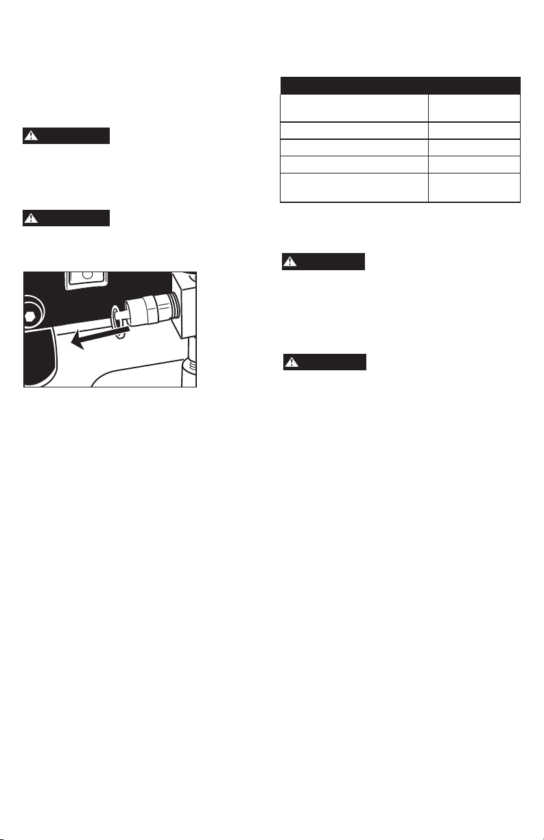
4. Connect the air hose to the quick connect socket
on the regulator assembly by inserting the
quick connect plug on the air hose into the
quickconnect socket. The quick connect socket
collar will snap forward and lock the plug into
place providing an air tight seal between the
socket and plug. To release the air hose push the
collar back on the quick connect socket.
4
5. Plug the power cord into the proper receptacle.
6. Turn the On/Off switch to the On position and the
compressor will start and build air pressure in the
tank to cut-out pressure and then
shut off automatically.
7. Adjust the regulator to a PSI setting that is needed
for your application and be sure it is within the
safety standards required to perform the task.
If using a pneumatic tool, the manufacturer
should have recommendations in the manual for
that particular tool on operating PSI settings.
8. The air compressor is now ready for use.
1
7
6
3
Daily Shut-Down Procedures
1. Set the On/Off switch to the Off position.
2. Unplug the power cord from the receptacle.
3. Set the outlet pressure to zero on the regulator.
4. Remove any air tools or accessories.
5. Open the drain valve allowing air to bleed from
the tank. After all of the air has bled from the tank,
close the drain valve to prevent debris buildup in
the valve.
5
CAUTION
When draining the tank, always use ear and eye
protection. Drain the tank in a suitable location;
condensation will be present in most cases of
draining.
WARNING
Water that remains in the tank during storage will
corrode and weaken the air tank which could cause
the tank to rupture. To avoid serious injury, be sure
to drain the tank after each use or daily.
5
Maintenance
NOTE: Any service procedure not covered in the
maintenance schedule should be performed by
qualified service personnel.
WARNING
The air compressor should be turned off,
unplugged from the power source, air bled from
the tank and allowed time to cool before any
maintenance is performed.
WARNING
Do not attempt to remove or adjust the
safety valve.
Check the safety valve by performing these
three steps:
1. Plug the compressor in and run until shut-off
pressure is reached.
2. Wearing safety glasses, pull out on the safety valve
ring to release pressure from the tank.
3. The safety valve should close automatically at
approximately at 40-50 PSI. If the safety valve
does not allow air to be released when you pull
out on the ring, or does not close automatically,
it must be replaced.
Maintenance Schedule
Items to Check/Change
Check Tank Safety Valve X
Overall Unit Visual Check X
Drain Tank X
Check Power Cord for
Damage
CAUTION
To ensure efficient operation and longer life of the
air compressor unit, a routine maintenance schedule
should be followed. The following schedule is geared
toward a consumer whose compressor is used in a
normal working environment on a daily basis.
CAUTION
This compressor is equipped with an automatic reset
thermal overload protector which will shut off motor
if it becomes overheated. If the thermal overload
protector is actuated, the motor must be allowed to
cool down before start-up is possible.
NOTE: The motor will automatically restart without
warning if the unit is left plugged into an outlet with
the On/Off switch in the On position.
Before each use
or daily
X
Storage
For storing the air compressor, be sure to do the following:
1. Turn the unit off and unplug the power cord from
the receptacle.
2. Remove all air hoses, accessories,
and air tools from the air compressor.
3. Perform the daily maintenance schedule.
4. Open the drain valve to bleed all air from the tank.
5. Close the drain valve.
6. Store the air compressor in a clean and dry location.
6
 Loading...