

Craftsman 921153640 Owner’s Manual

Owner's ManuaJ
[eRRMn.i
AIR COMPRESSOR
7-gallon
1 HP
Oil Lubricated
Model No. 921.153640
\
\
\
CAUTION:
Before using this product, read this
manual and follow all its Safety
Rules and Operating instructions.
Sears Brands Management Corporation
Hoffman Estates, IL 60179 U.S.A.
www.sears.com/craftsman
08/08/2013
Part No. E106547
• Safety instructions
• installation & Operation
• Maintenance & Storage
• Troubleshooting Guide
• Parts List

TABLE OF CONTENTS
Page
Warranty ................................................................ see below
Safety Symbols ................................................................... 1
important Safety Instructions & Guidelines .............................................. 1
Specifications .................................................................... 2
Glossary ........................................................................ 2
Duty Cycle ....................................................................... 2
Parts & Features .................................................................. 3
installation & Assembly ............................................................. 4
Operating Procedures .............................................................. 6
Maintenance ..................................................................... 7
Storage ......................................................................... 7
Troubleshooting Guide ............................................................. 8
Exploded View ................................................................... 9
Parts List ...................................................................... 10
Service Number ........................................................... back cover
CRAFTSMAN ONE YEAR FULL WARRANTY
FOR ONE YEAR from the date of purchase, this product is warranted against any defects in material
or workmanship. A defective product will receive free repair or replacement if repair is unavailable.
For warranty coverage details to receive free repair or replacement, visit the web site: www.craftsman.com
This warranty is void if this product is ever used while providing commercial services or if rented to
another person.
This warranty gives you specific legal rights, and you may also have other rights which vary from state
to state.
Sears Brands Management Corporation, Hoffman Estates, IL 60179 U.S.A.
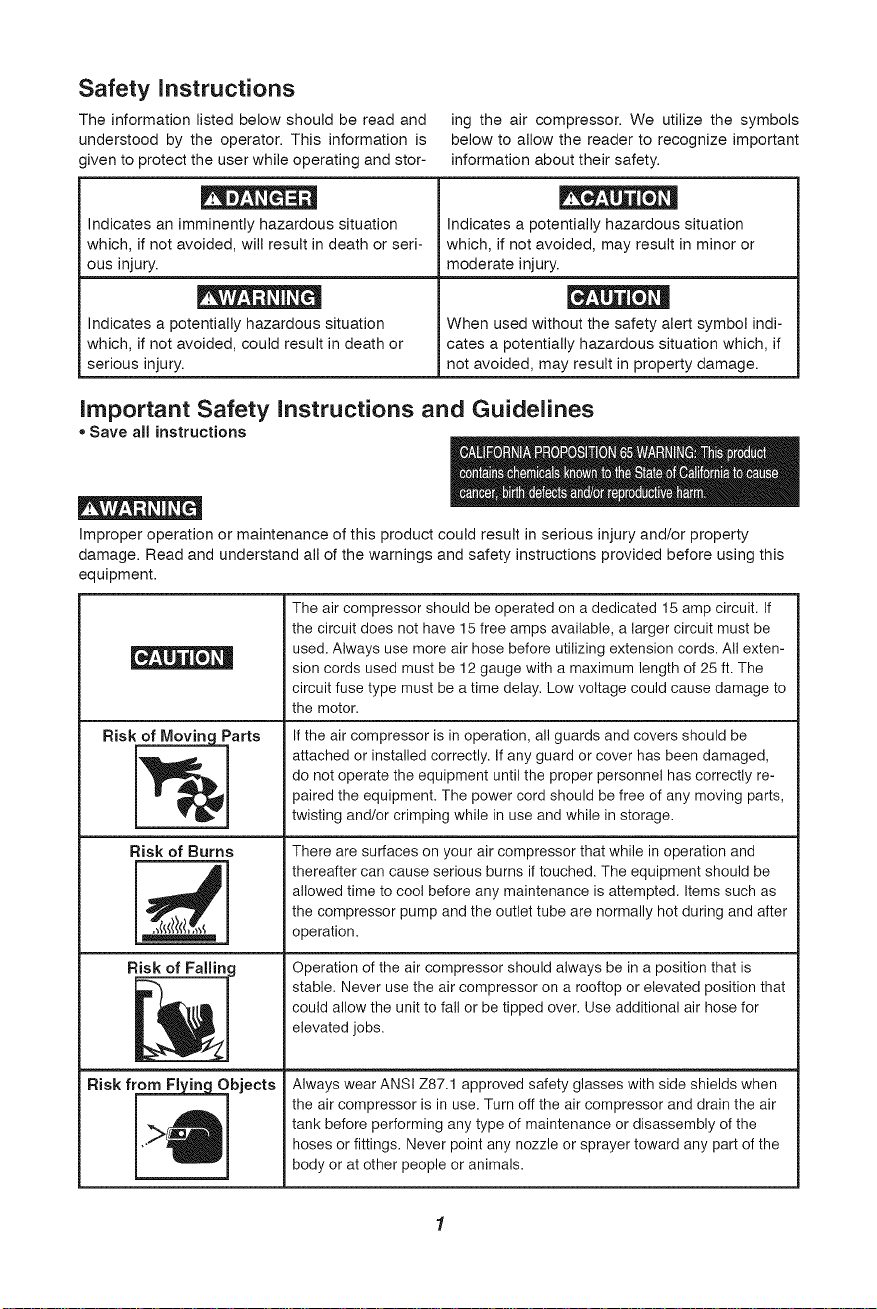
Safety Instructions
The information listed below should be read and
understood by the operator. This information is
given to protect the user while operating and stor-
ing the air compressor. We utilize the symbols
below to allow the reader to recognize important
information about their safety.
Indicates an imminently hazardous situation
which, if not avoided, will result in death or seri-
ous injury.
Indicates a potentially hazardous situation
which, if not avoided, could result in death or
serious injury.
Indicates a potentially hazardous situation
which, if not avoided, may result in minor or
moderate injury.
When used without the safety alert symbol indi-
cates a potentially hazardous situation which, if
not avoided, may result in property damage.
Important Safety Instructions and Guidelines
* Save all instructions
Improper operation or maintenance of this product could result in serious injury and/or property
damage. Read and understand all of the warnings and safety instructions provided before using this
equipment.
The air compressor should be operated on a dedicated 15 amp circuit. If
the circuit does not have 15 free amps available, a larger circuit must be
used. Always use more air hose before utilizing extension cords. All exten-
sion cords used must be 12 gauge with a maximum length of 25 ft. The
circuit fuse type must be a time delay. Low voltage could cause damage to
the motor.
Risk of Moving_Parts
Risk of Burns
If the air compressor is in operation, all guards and covers should be
attached or installed correctly. If any guard or cover has been damaged,
do not operate the equipment until the proper personnel has correctly re-
paired the equipment. The power cord should be free of any moving parts,
twisting and/or crimping while in use and while instorage.
There are surfaces on your air compressor that while in operation and
thereafter can cause serious burns if touched. The equipment should be
allowed time to cool before any maintenance is attempted. Items such as
the compressor pump and the outlet tube are normally hot during and after
operation.
Risk of Falling
Risk fromFl_Objects
Operation of the air compressor should always be in a position that is
stable. Never use the air compressor on a rooftop or elevated position that
could allow the unit to fall or be tipped over. Use additional air hose for
elevated jobs.
Always wear ANSI Z87.1 approved safety glasses with side shields when
the air compressor is in use. Turn off the air compressor and drain the air
tank before performing any type of maintenance or disassembly of the
hoses or fittings. Never point any nozzle or sprayer toward any part of the
body or at other people or animals.

Important Safety Instructions & Guidelines
Risk to Breathing
Risk of Electrical Shock
Risk of
E_ _losion or Fire
Risk of Bursting
Avoid using the air compressor in confined areas. Always have adequate
space (12 inches) on all sides of the air compressor. Also keep children,
pets, and others out of the area of operation. This air compressor does
not provide breathable air for anyone or any auxiliary breathing device.
Spraying material will always need to be in another area away from the air
compressor to not allow intake air to damage the air compressor filter.
Never utilize the air compressor in the rain or wet conditions. Any electrical
issues or repairs should be performed by authorized personnel such as an
electrician and should comply with all national and local electrical codes.
The air compressor should also have the proper three prong grounding
plug, correct voltage, and adequate fuse protection.
Never operate the compressor near combustible materials, gasoline or
solvent vapors. If spraying flammable materials, locate the air compressor
at least 20 feet away from the spray area. Never operate the air compres-
sor indoors or in a confined area.
Always drain the air compressor tank daily or after each use. If the tank
develops a leak, then replace the air compressor. Never use the air com-
pressor after a leak has been found or try to make any modifications to the
tank. Never modify the air compressor's factory settings which control the
tank pressure or any other function.
Specifications
Pump .................. Oil-lube direct drive
Motor ................... 1.0 HP (induction)
Bore ............................... 1.65"
Stroke .............................. 1.26"
Voltage Single Phase ............... 120 VAC
Minimum Circuit Requirement ........ 15 Amps
Air Tank Capacity ................. 7 Gallons
Cut-in Pressure ................... 105 PSI
Cut-out Pressure .................. 135 PSI
SCFM @ 90 PSI ....................... 2.4
Oil Capacity ................. 90 mL or 3 oz.
Oil Type . SAE 30 Non-detergent Semi Synthetic
Glossary
CFM: Cubic feet per minute.
SCFM: Standard cubic feet per minute; a unit of
measure for air delivery.
PSIG: Pounds per square inch gauge; a unit of
measure for pressure.
ASME: American Society of Mechanical Engineers.
California Code: Unit may comply with California
Code 462 (I) (2)/(M) (2).
Cut-In Pressure: The air compressor will
automatically start to refill the tank when
the pressure drops below the prescribed
minimum.
Cut-Out Pressure: The point at which the motor
stops when the tank has reached maximum
air pressure.
Code Certification: Products that bear one or
more of the following marks: UL, CUL,
ETL, CSA, have been evaluated by OSHA-
certified independent safety laboratories
and meet the applicable Underwriters
Laboratories Standards for Safety.
Duty Cycle
This is a 50% duty cycle air compressor. Do not run the air compressor more than 30 minutes of
one hour. Doing so could damage the air compressor.
2

Parts & Features
See figures below for reference
Provides clean air to the pump and must
always be kept free of debris. Check on a
Air intake Filter 1
daily basis or before each use.
=Oil Fill Cap
=Oil Sight Gauge
Pressure
Relief Tube
!
!
Outlet
Tube
Tank Pressure Gauge
Indicates the reserve air pressure in the tank.
This controls the power to the motor and also
the cut-in/cut-out pressure settings.
This switch serves as the Auto-On/Off
Pressure Switch l
positions for the unit.
Indicates the outgoing air pressure to the
Regulator Gauge 1
tool and is controlled by the regulator.
Regulator
_" The air pressure coming from
J the pressure, !urn the knob
the air tank is controlled by
the regulator. To increase
the pressure, turn the knob
clockwise, and to decrease
Drain Valve
Used to drain condensation from the
air tank. Located at bottom of tank.
When the pump is not in operation the valve
closes to retain air pressure inside the tank. Ar
internal component.
\ I Offers a quick release featurel
/ I for attaching and removing |
_ _. the air hose. i)
The pressure relief valve located on the
side of the pressure switch, is designed to
automatically release compressed air when th_
air compressor reaches cut-out pressure. The
I Pressure Relief Valve
released air should only escape momentarily
and the valve should then close.
Tank Safety Valve
Used to allow excess tank pressure to escape
into the atmosphere. This valve should only open
when the tank pressure is above the maximum
'l i
rated pressure.

Installation & Assembly
The air compressor should be turned off, unplugged from the power source, the air bled from the tank
and the unit allowed time to cool before any maintenance is performed. Personal injuries could occur
from moving parts, electrical sources, compressed air or hot surfaces. The quick connect assembly
must be attached before use. Failure to assemble correctly could result in leaks and possible injury. If
unsure of assembly instructions or you experience difficulty in the assembly please contact your local
authorized Sears or another qualified service dealer.
Assembly
Installing Wheels
The wheels and handle do not provide adequate
clearance, stability or support for pulling the unit
up and down stairs or steps. The unit must be
lifted or pushed up a ramp.
It may be necessary to brace or support one end
of the air compressor when attaching the wheels,
because it will have a tendency to tip.
1. Remove air compressor, manual, air filter
assembly, and accessories from packaging.
2. Remove the plastic plug from the compressor
intake port. (see diagram below)
3. Install the filter in the compressor intake port.
(see diagram below)
4. Remove the oil fill cap from the crankcase and
fill until the oil reaches the top of the red dot in
the sight glass. Oil capacity is 3 oz. (see below)
Use SAE 30 Non-detergent Semi Synthetic
oil (API CG/CD heavy duty motor oil). Under
extreme cold weather conditions use SAE-10
weight oil.
5. Replace the oil cap.
items Needed For Assembly
19mm or adjustable wrench for shoulder bolt
17mm or adjustable wrench for nylon lock nut
Install one shoulder bolt, washer, and one nut
for each wheel using bolt holes provided in the
wheel bracket. The shoulder bolt will install from
the outside of the wheel through the top hole
in the wheel bracket. Tighten securely with the
washer and nut positioned on the inside of the
wheel bracket.
Estimated Assembly Time:
Approximately 5 minutes

Installation & Assembly
Getting Started -
Location of the Air Compressor
The air compressor should always be located
in a clean, dry and well ventilated environment.
The unit should have at minimum, 12 inches of
space on each side. The air filter intake should
be free of any debris or obstructions. Check the
air filter on a daily basis to make sure it is clean
and in working order.
Grounding Instructions
This product should be grounded. In the event of
an electrical short circuit, grounding reduces the
risk of electric shock by providing an escape wire
for the electric current. This product is equipped
with a cord having a grounding wire with an ap-
propriate grounding plug. (See the figure below.)
The plug must be plugged into an outlet that is
properly installed and grounded in accordance
with all local codes and ordinances. Check with
a qualified electrician or service personnel if
these instructions are not completely understood
or if in doubt as to whether the tool is properly
grounded.
Grounded
i
Outlet
Make sure that the product is connected to an
outlet having the same configuration as the plug.
No adapter should be used with this product. If
the product must be reconnected for use on a
different type of electric circuit, qualified service
personnel should make the reconnection.
Extension Cords
Use only a 3-wire extension cord that has a
3-blade grounding plug, and a 3-slot receptacle
that will accept the plug on the product. Make
sure your extension cord is in good condition.
When using an extension cord, be sure to use
one heavy enough to carry the current your
product will draw. Cords must not exceed 25
feet and No. 12 AWG size must be used. An
undersized cord will cause a drop in line voltage
resulting in loss of power and overheating.
Break In Procedures
No break in procedure is required by the user.
This product is factory tested to ensure proper
operation and performance.
Grounding Pin
Improper installation of the grounding plug will
result in a risk of electric shock. If repair or
replacement of the cord or plug is necessary,
do not connect the grounding wire to either flat
blade terminal. The wire with insulation having
an outer surface that is green with or without
yellow stripes is the grounding wire. Check
with a qualified electrician or serviceman if
the grounding instructions are not completely
understood, or if in doubt as to whether the
product is properly grounded. Do not modify the
plug provided; if it will not fit the outlet, have the
proper outlet installed by a qualified electrician.
This product is for use on a circuit having a
nominal rating of 120 volts and is factory-
equipped with a specific electric cord and plug
to permit connection to a proper electric circuit.

Operating Procedures
Daily Start-Up Procedures
1. Set the Auto-On/Off lever to the Off position.
2. Inspect the air compressor, air hose, and any
accessories/tools being used for damage or
obstruction, if any of these mentioned items
are inneed of repair!replacement, contact
your localauthorized service dealer before use.
3. Close the drain valve.
4. Check the oil level of the pump.
5. Connect the air hose to the quick connect
socket on the regulator assembly by inserting
the quick connect plug on the air hose into
the quick connect socket. The quick connect
socket collar will snap forward and lock
the plug into place providing an air tight seal
between the socket and plug. To release the
air hose push the collar back on the quick
connect socket.
®
6. Plug the power cord into the proper receptacle.
7. Turn the Auto-On/Off lever to the On-Auto
position and the compressor will start and
build air pressure in the tank to cut-out
pressure and then shut off automatically.
8. Adjust the regulator to a PSI setting that is
needed for your application and be sure it is
within the safety standards required to
perform the task. If using a pneumatic tool,
the manufacturer should have recommendations
inthe manual for that particular tool on operating
PSI settings.
9. The air compressor is now ready for use.
Daily Shut-Down Procedures
1. Set the Auto-On/Off lever to the Off position.
2. Unplug the power cord from the receptacle.
3. Set the outlet pressure to zero on the regulator.
4. Remove any air tools or accessories. When
draining the tank, always use ear and eye
protection. Drain the tank in a suitable location;
condensation will be present in most cases
of draining.
5. Open the drain valve allowing air to bleed from
the tank. After all of the air has bled from
the tank, close the drain valve to prevent
debris buildup in the valve.
When draining the tank, always use ear and eye
protection. Drain the tank in a suitable location;
condensation will be present in most cases
of draining.
Water that remains in the tank during storage
will corrode and weaken the air tank which could
cause the tank to rupture. To avoid serious injury,
be sure to drain the tank after each use or daily.

Maintenance
NOTE: Any service procedure not covered in the maintenance schedule should be performed
by qualified service personnel Contact your local authorized Sears or another qualified ser-
vice dealer.
The air compressor should be turned off,
unplugged from the power source, air bled from
the tank and allowed time to cool before any
maintenance is performed.
To ensure efficient operation and longer life of
the air compressor unit, a routine maintenance
schedule should be followed. The following
schedule is geared toward a consumer whose
compressor is used in a normal working environ-
ment on a daily basis.
Items to Check/Change
Check Tank Safety Valve
Overall Unit Visual Check
Check Air Filter
DrainTank
Check PowerCord for Damage
Change Oil
Check Oil Level
Before each use
or daily
X
X
X
X
X
afterfirst10hours
afterevery100hours
X
Storage
For storing the air compressor, be sure to do the following:
1. Turn the unit off and unplug the power cord 4. Open the drain valve to bleed all air from the tank.
from the receptacle. 5. Close the drain valve.
2. Remove all air hoses, accessories, and air tools 6. Store the air compressor in a clean and
from the air compressor, dry location.
3. Perform the daily maintenance schedule.
,-- NOTES -.
7
 Loading...