

Page 1
Owner’s Manual
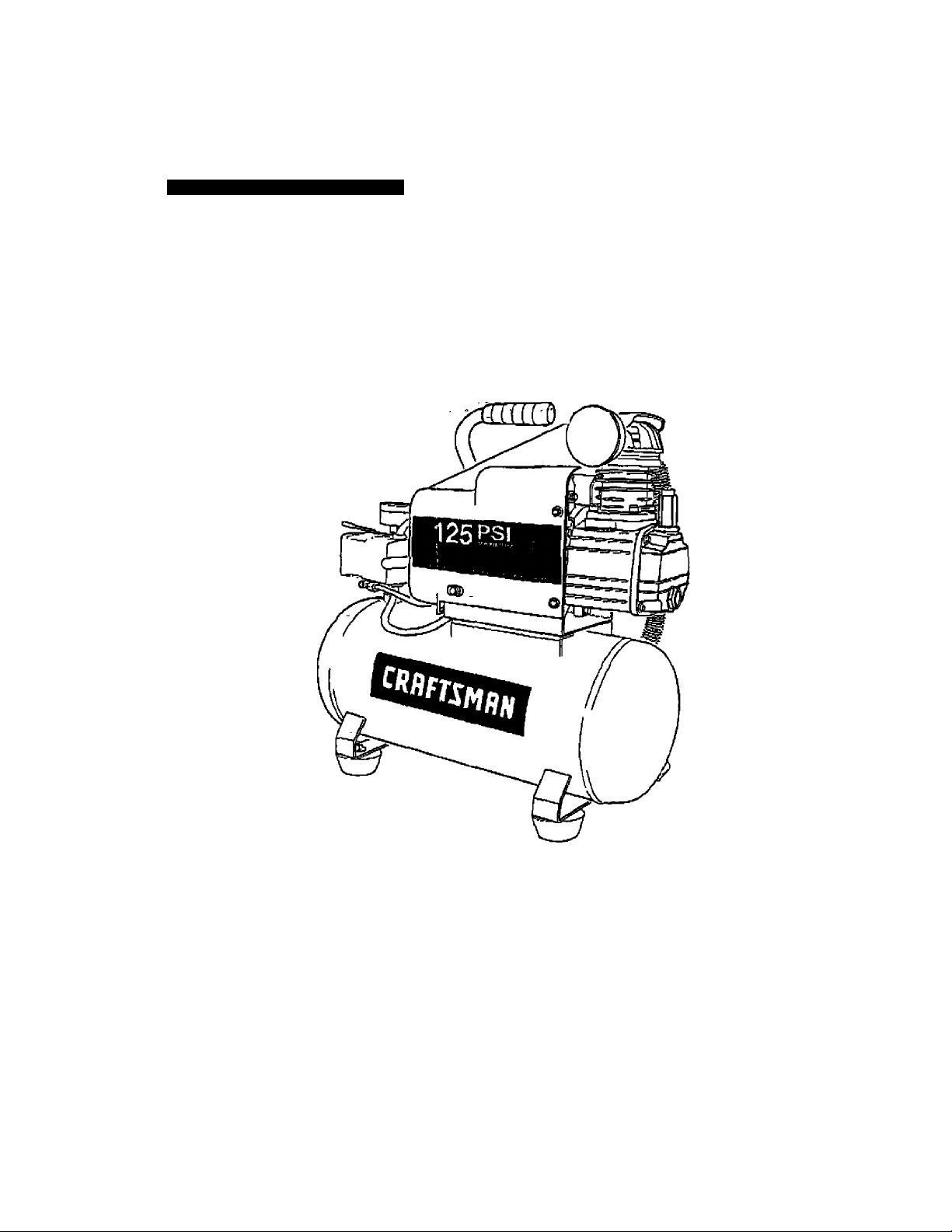
AIR COMPRESSOR
3-gallon
1.6 HP (max developed)
1 HP Running
Oil Lubricated
Model No. 921.153101
CAUTION:
Before using this product,
read this manual and follow
all Its Safety Rules and
Operating Instructions.
Sears, Roebuck and Co., Hoffman Estates, IL 60179 U.S.A,
www.eeai’s.com/craftsman
11/1ZSOM
Pan No E101139
Safety Instructtons
tnstallation & Operation
Matntenance & Storage
Troubleshooting Guide
Parts List
Español, p. 10
Page 2

TABLE OF CONTENTS
Page
Warranty,
Safety Instructions
Important Safety Instructions & Guidelines
Specifications.........................................................................
Glossary-
Duty Cyde
Parts & Features
Installation & Assembly......................................................
Operating Procedures............................................................
Maintenance...........................................................................
Storage..................................................................................
Troubleshooting Guide.
.................................. ..............................-
............................................-................................
....................... ..........................................
............................
........
....................................................................
.
see below
1
1
2
2
2
3
4
5
6
6
7
Parts Ust
Español
Service Number................................................................................ back cover
...................
.....................
3
10
ONE YEAR FULL WARRANTY ON CRAFTSMAN AIR COMPRESSOR
If this Craftsman Air Compressor fails due to manufacturafs defects in material or workmanship
within one year of the date of purchase, RETURN IT TO THE NEAREST SEARS STORE OR
SERVICE CENTER IN THE UNITED STATES and It will be replaced or repaired (at our option),
free of charge .
If this Air Compressor is used for commercial or rental purposes, this warranty applies for only 90
days from the date of purchase. This warranty gives you spedfic legal rights and you may also
have other rights which vary from state to state
Sears, Roebuck and Co., DepL 61 TWA,
HoTfman Estates. IL $0179
Page 3
Safety Instructions
The information iistsd below should be read and
understood by the operator. This inforrnation is given to
protect the user while operating and storing the air
compressor. We utffize the symbols below to allow the
reader to recognize important information about their
safety
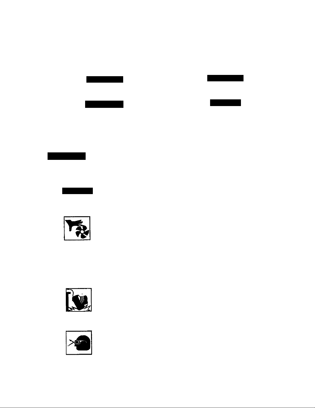
A DANGER
Indicates an imminently hazardous situation which, if not
avoided, will result in death or serious injury.
A WARNING
Indicates a potentially hazardous situatian which, if not
avoided, could resuK in death or serious injury
Indicates a potentially hazardous situation which, if not
avoided, may result in minor or moderate injury
When used without (he safety alert symbol indicates a
potentfaliy hazardous situation virhich. if not avoided, may
- t)»ult in propeity damage.;
A CAUTION
CAUTION
Important Safety Instructions and Guidelines
• Sav0 all Instructions
A WARNING
Improper operation or maintenance of this product could resuh In serious injury and/or property damage. Read and
understand all of the warnings and safety instructions provided before using this equipment
The air compressor should be operated on a dedicated I5amp circuit. If the circuit does
not have 15 free amps availabis, a larger circuit must be used. Always use more air
CAUTION
Risk of Moving Parts
-hose before utitizirtg extension cords. All extension cords used must be 12 gauge with
a maximum len^i of 25 ft. The circuit fuse type must be a time delay. Low voltage could
cause damage to the motor. -
If the air compressor is In operation, all guards and covers should be attached or
installed correctly. If any guard or cover has been damaged, do not operate the
'equipment until the proper personnel has cotrectly repaired the equipment The power
-cord should be free of any moving parts, twisting and/or crimping while in use and while
in storage.
Risk of Burns
Risk of Falling
Risk from
Flying Objects
There are surfaces on your air compressor that while in operation and thereafter can
cause serious burns If touched. The equipment should be allowed time to cool before
any maintenance is attempted. Items such as the compressor pump and the outlet tube
are normally hot during arid after operation.
Gyration of the air compressor should always be in a posidon that is stable. Never use
the air compressor on a rooftop or elevated position that could allow the unit to fall or
-be tipped over. Use additional air hose for elevated jobs.
Always wear ANSI Z87.1 approved safety glasses with side shields virhen the air
compressor is in use. Turn off the air compressor and drain the air tank before
performing any type of maintenance or disassembly of the hoses or fittings. Never point
any nozzle or sprayer toward any part of the body or at other people or animals.
Page 4
Important Satoty Insinielions & Quit/ellneB
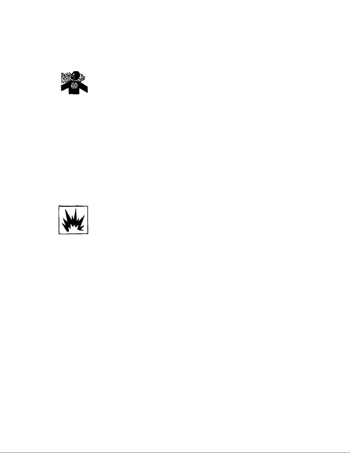
Risk to Breathing
Risk of
Electrical Shock
'i*
. V
RisIlOf
Explosion oi nn
Rick of Bursting
Avoid using ihs air compressor In conHnod areas. Always have adequate space
(12 inches) on all sktas oF the air oompreasor. Also keep children, pats, and others out
of the area of operation. This air compressor does net provide breathable air for anyone
or any auMliary breathing device. Spraying material will always need to be in another
area away from the air compressor to not allow Intake air to damage the air compressor
filter,
Never utilize tha air compressor in the ram or wet conditions. Any electrical issues or
repairs should be performed by autiiorized peiaonnel such as an electrician and should
comply with all national and local electrical codes. The air compressor should also have
the proper three prong groundmg plug, correct voltage, and adequate fuse protection.
fNayer opeóte tte compresor.near combustible materials, garollne'cr soKjerit ya^j^;'
If spraying flammable materials, locate me air compressor at least 20 feet array from
the spray area. Never operate the air compressor indoors or In a confined area
Always drain the air compressor tank daily or after each use. If the tank develops a leak,
then replace the air compressor. Never use the air compressor after a leak has been
found or try to make any modifications to the tank. Never modify the air compressor's
factory settings which control the tank pressure or any other fundón.
■- ^ " r_ ■»
Specifications
Pump .........................................Oil-lube direct drive-
Motor Induction
Bore
.................
Stroke
............
Voltage Single Phase
.........................
..........................1.65"
1.S HP max developed,
1 HP tunning
........................1,26"
....... ........
>20 VAC
Glossary
CFM: Cubic feet per minute.
SCFM: Standard cubic Feet per minute; a unit of maasure
for air dellve^.
PSIG: Pounds per square Inch gauge; a unit of measure
ASME: American Society of Mechanical Engineers.
California Code: Unit rnsy comply with Canfomla Code
for pressure.
462 (I) (2)/ (M) (2).
Cut'In Pressure; The air compressor will automatically
start to refill the tank when the pressure drops
below the prescribed minimum
Duty Cycle
This IS a 50% duty cycle air compressor. Do not run the air
could damage toe air compressor.
compressor more than 30 minutes of one hour. Doing sc
Minimum Circuit Requirement__15 Amps
Air Tank Capacity
Cul4n Pressure
Cut-out Pressure
SCFMOSOPSI.............................2.4
Cui-Out Pressure; The point at which the motor stops
when the tank has reached maximum air
pressure.
Code Certification: Products that bear one or more of -
the following marks: UL, CUL,'ETL, CSA, have ■
been evaluated by OSHA-oertifled Independent
safety laboratories and meet the applicable
Underwriters Laboratories Standards for Safety
.....................
...........................
...................
. .125 PSI
^ Gatigns
95 PSI
Page 5

Parts & Features
Sea figures below for rsferance.
Air Intake Filter
Provides clean air to the pump and must always be kept free of debns. Check on a daily basis or before each use.
Regulator Gauge
Indicates the outgoing air pressure to the tool and Is controlled
by the regulator.
Tank Pressure Gauge
Indicates the reserve air pressure in the tank.
Pressure dwitch ...
This controls the power to the motor apd-alra tHe.'-:cut-in/cut-out pressure settings. This switch sst^e'
as the Auto-On/Off positions for the unit.
Pressure Relief Valve
The pressure relief! valve located on the
side of the pressure sviritch, is designed to
automatically release compressed air when
the air compressor reaches oit-out pressure.
The reieased air shoidd only esc^s
momentarily and №e valve should then dose.'
_____
Tank Safety Valve
Used to allow excess tank pressure to
escape into the atmosphere. This valve
should only open when the tank pressure
^ is above the maximum rated pressure.
RMUIator
Tne air pressure coming from the air tank is
controlled by the regulator To increase the
pressure turn the knob clockwise and to
decrease the pressure turn the knob ■
counterclockwise.
Quick Connect
Offers a quick release feature for attaching and removing the air hose.
Tank Drain Va^e
Used to drain condensation from the air tank. Located at bottom of tank: :
Check Valve
When the pump is not in operation the valve closes to retain air pressure insido the tank. An internal component.
Page 6

Installation & Assembly
A WARNING
Ths air coTDpressor should bo turned oft and unplugged from the
power source before any maintenance is performed as well as
the air bled from the lank and iha unit allowed time
to cool. Personal Injunes could occur from moving parts, electri
cal sources, compressed air or hot surfaces. The
regulator assembly must be attached before use. Failure to
assemble correctly could resuh In leaks and possible Injury
If unsure ol assembly instructions or you expedence difficulty in
the assembly please call your local service department lor further
Instructioti.
Quick Connect Assembly
1. Before assembly be sure that the
Quick Connea (Q C.) threads have a
sealant applied from the factory to prevent
leaks around the threads. If no seaiarrt is
present, vurap the threaded portion vvHh
Teflon taps.
2 Remove the regulator's plastic plug. Attach
the O C. assembly to the air compressor by aligning the Q.C
threads to the regulator on the manifold. Be certain to align
the threads before tightening to prevent thread damage
3. After hand tightening, the assembly should be turned clock
wise 1 to 1.5 revolutions with a I3^6ihe size wrench.
To prevent damage and leaks, do nor over-tighten
To Install the Air Intake Rltsr
Remove the plastic plug from the
compressor head. Remove the air intake
filler from the poly bag and thread it onto the
head of the compressor as shown.
A CAUTION
Do not attempt to star the air compressor
without first adding oil to the crankcase Serious damage can
result unless fffied with oil The pump Is shipped without oil from
the factory. Only use non-dstergent oils since multf-vlscostiy
motor oils leave carbon deposits on pURip eomponems, thus
redudng petfetTnanee and compressor life.
A WARNING
Drain the tank to release all tank air
pressure before removing the oD flit cap. Be sure the air vant in
the oU fill cap (see figure lo the right) is free \
from debris, if air vent Is blocked, pressure \
can buttd In crankcase causing damage to ^
the compressor and possible personal Injury.
Lubrication and Oil
Remove the oil fill cap by turning it .
counter-clockwise by hand. Fill the
compressor pump with an air compressor oil such as SAE-30
rton-detergent (API CG/CD Heavy Duty) oU
at slow intervals undl the oil reaches the
center of the red circle In the sight glass
( see figure above). Use SAE-10 during
extreme winter conditions.
Location of the Air Compressor
The air compressor should always be located In a dean,
dry, and welt venttlalsd envinonment. The unit should have
at minimum, 13 Inches of apace on each side. The air IBiar intake
should be kee ol any debns or obstructiorrs. Check the air filter
on a dally basis to be sure it is dean and in working order
Grounding Inatructlons
This product should be grounded. In the event ol an elecirical
short circuit, grounding reduces the risk of electric eho^ by pro
viding an escape wire for the eiectrlc cutrenL This product is
equipped with a cord having a grounding wire with an appropri
ate groundng plug. (See the figure below) The plug must be
plugged into an outlet that Is properly Installed and grourtded h
acoordanoB whh an local codes and ordinances Check with a
qualified eiectrlcian orservlca
personnel If these
instructions are not
completely understood
or II in doubt as to
whether the tool Is
properly grounded Q/tamding pin
A WARNING
Improper Installation of the grounding plug virlll result In a
nsk of electric ehock. IF repair or replacement of the cord
or plug Is neceseary, do not connect foe grounding wire to either
flat blade terminal. The wire with insulation having an outer sur
face that Is green wfth or wlfoout yellow stripes Is the grounding
wire Cheek with a qualified electrician or serviceman if foe
grounding instructions are not completely understood, or if m
doubt as to whether the product is properly grounded. Do not
modlty the plug provided, It It will not lit foe outlsL have the prop
ar outlet installed by a qualified electrician.
This product Is for use on a tircuit having a nominal rating
oM30 volts and Is lactory-equlpped with aspecifie electric cord
and plug to permit connection to a proper electric circuit Make
sure that the product Is connected to an outlet havtng the same
configuration as the plug. No adapter should be used with this
product H the product must be reconnected for use on a diffen
ent type of etecirle circuit qualified service personnel should
make foe reconnection,
Extension Cords
Use only a S^wtre extension cord that has a 3-blade
grounding plug, and a 3-8tot receptacle that vnll accept the plug
on the product Make sure your extension cord is In good condi
tion. Whan using an extension cord, be sure to use one heavy
enough to carry foe current your product will draw. Cords must
not exceed 25 feet and No. 12 AWG size must be used An
undersized cord wiR cause a drop In line voltage resulting In loss
ol power end overheating.
Break In Procedures
No break in procedure is required by foa user. This
product Is factory tested to ensure proper operation and
performance
grounded
Oum
Page 7

operating Procedures
Dally Start-Up Procedures
© Set the Auto-On/Off lever to the Off position.
@ Check the air compressor visually for any damage
or obstruction.
® Close the drain valve.
® Check the oil level of the pump
® Connect the air hose to the quick connect socket on
the regulator assembly by inserting the quick connect
plug on the air hose into the quick connect socket. The
quick connect socket collar will snap fonvard and lock
the plug into place providing an air tigfrt seal between
the socket and plug. To release the air hose push the
collar back on the quick connect socket.
© Plug the power cord into the proper receptacle
©Turn the Auto-On/Otf lever to the On-Auto position and
the compressor will start and build air pressure In the
tank to cut-out pressure and then shut off automatically
© Adjust the regulator to a PSI setting that Is needed for
your application and be sure it is within the safety
standards required to perform the task, if using a
pneumatic tool, the manufacturer should have
recommendations in the manual for that particular
tool on operating PSI settings.
Note: The air compressor is now ready for use. The
following Inflation and cleaning accessories packaged
with this unit should only be operated at maximum
pressure of 20-30 PSI: blow gun. tapered nozzle, inflation needles, blow gun adapter.
Dally Shut-Down Procedurea
1. Set the Auto-OnfOff lever to the Off position
2. Unplug the power cord from the receptacle.
3. Set the outlet pressure to zero on the regulator.
4. Remove any air tools or accessories. When draining
the tank, always use ear and eye protection. Drain the
tank in a suitable location; ciondensation will be present
in most cases of draining.
5. Open the drain valve allowing air to bleed from the
tank. After all of the air has bled from the tank, close
the drain valve to prevent debns buildup in the valve.
A CAUTION
lA/hen draining the tank, always use ear and eye piotection.
Drain the tank in a suitable location; condensation will be
present In rnost cases of draining.
A WARNING
Water that remains In the tank dunng storage will corrode
and weaken the sir tank which could cause the tank to
rupture. To avoid senous injury, be sure to drain the tank
after each use or daily.
Page 8

Maintenance
NOTE: Any service procedure not covered in tSn maintenance sctieduie below should be performed by qualiFied service
personnel.
Items to Check/Change
Check Tank Safety Valve
Overall Unit Visual Check
Check Oil Level ~
Change Oil
Check Air Rlter (more frequently in dusty or humid environments)
Drain Tank (after each use or daily)
Before each
use or dally
X
X
X
X
X
After first
10 hours
X X
Every
100 hours
A CAUTION
To ensure efficient operation and longer life of the air
compressor unit, a routine msintenance schedule should
be followed The following schedule is geared toward a
consumer whose compressor la used in a normal working
environment on a daily basis. IF necessary, the schedule
should be modified to suit the conditions under which your
compressor is used The modifications will depend upon
the hours of operation and the working environment. Air
compressors used in an extremely dirty and/or hostile
environment will require a greater frequency of all
maintenance checks.
Oil Changing
For changing the pump oil, be sure to do the followirtg:
1. Turn the unit off at>d unplug the power cord from the
receptacle.
2. Allow the compressor time to cool it It has been in
operation.
3 Open the dram valve to bleed all air from the tank.
4 Close the dram valve.
5. Remove the oil fill cap on the pump.
6 Remove the sight glass with a box end wrench or
socket. Drain the oil Into a suitable container and
dispose of properly. The compressor may neeiJ to be
tipped slightly towards the drain hole to allow all of the
oil to drain.
A WARNING
The air compressor should be turned off and unplugged
from the power source before eny maintenance is
performed as well as ihe air bled from the tank and the
unit allowed time to cool Personal Injuries could occur
from moving parts, electrical sources, compressed air or
hot surfaces.
7. Reatta^ the sight glass Note: Torque the sight glass
10-12 mch lbs. when re-assembling. Be sure the gasket
is between the sight glass and the pump crankcase.
8. Refill the compressor pump vi^h an air compressor oil
such as SAE-30 non-detergent (APt CG/CD Heavy
Duty) oil at slow Intervals untit the o'd reaches the center
of the red arde in №e sight glass Use a SAE-10 during
extreme winter conditions.
Storage
For storing the air compressor, be sure to do the following
1, Turn the unit off and unplug the power cord from the
receptacle.
2 Remove ail air hoses, accessories, and air toole from
the air compressor.
3. Perform the daily maintenance schedule.
4. Open the drain valve to bleed all air from the tank
5. Close the drain valve.
6. Store the air compressor in a dean and dry location.
Page 9

Troubleshooting Guide
A WARNING
Personal injuries could occur from moving parts, olectrical sources, compressed air, or hot surfaces
PROBLEM
Air leaks at the check valve
or at the pressure relief valve.
Air leaks between head and
cylinder.
Air leak from safety valve. Operate the safety valve manually by pulling on the ring, If the valve continues to
Pressure reeding on the
regulated pressure gauge
drops Mdien an accessory is
used.
Excessive tank pressure.
The air compressor should be turned off and unplugged from the power source before any
maintenance is performed as well es Che air bled from the tartk and the unit allowed time to cool
POSSIBLE CORRECTION
A defective check valve results in a constant air leak at the pressure relief valve
when there is pressure in the tank and the compressor is shut off. Drain the tank,
then remove and clean or replace the check valve
Be sure of proper torque on head bolts. If leak remains, contact a service technician.
leak when in the closed position, it should be replaced.
If there IS an excessive amount of pressure drop when the accessory is used,
replace the regulator.
NOTE:
Adjust the regulated pressure under flow conditions (while accessory is being used).
It is normal for the gauge to show minimal pressure loss during inidal use of №e
tool.
Move the Auto-On/Off lever to the Off position, if the unit doesn't shut off, unplug it
from the power source and contact a service technician.
Motor will not start.
Excessive moisture In the
discharge air.
Air leaks from the tank body
or tank welds
Make sure power cord is plugged in and the switch is on. Inspect for the proper size
fuse in your circuit box. If the fuse was tnpped, reset it and restart the unit, if
repeated tripping occurs, replace the check valve or contact a service technician.
Remove the water in the tank by draining after each use. High humidity
environments wii cause excessive condensation utilize water flltsra on your air
line.
NOTE:
Water condensation is not caused by compressor malfunction. Be sure the
compressor's iiir output is greater than your tool's air consumption rate.
Never drill into, weld or otherwise modify the air tank or it will weaken. The tank can
rupture or explode Compressor cannot be repaired, Discontinue use of the air
compressor.
Page 10

Craftsman Air Compressor Model 921,153101
Parts List
Page 11

Craftsman Air Compressor Model 921.153101
Parts List
Reference
Number
1
2
3
4
5
6 E1OQB09
7
6
9 E100229 Valve Reed
10
11
12 Cylinder, ID42mm x H65mm
13
14
15
16 3
17 3
IB 3
19 3
20
21 3
22
23
24
25
26
27
2B S
29
30
31
32 Screw, Round Head, Phillips,
33
34 El 00246
35
36
37
38
39
40
Kit Part
Number Number
El 00434
1
1 E10043S
E100227
2
El 00223
2 Gaakat, Valve Plate 1
2
2 Gasket, C^mdet Lower
3
3 Rod Connecting 1
3
4
4
El 01000
5
2
6
El 00247
E100955
El 00854
El 00956
Description Ouantitv
Intake Filter Housing,
1/2 NPT
Filter Eiernem
Screw, Socket Head,
M6xl.0x30mffl
Lock Washer, 6mm
Cyfinder Heed
Exhaust Elbow
Gasket, Head
Valve Plate
Gasket, CyTinder Upper
Screw, Socket Head,
M6x 1.0 X 20mm
Ring, Compression 2
Ring, Scraper
Piston
Piston pin
Snap Ring, 12mm
Nut,M6x1.0
Eccentric
Oil Fin Cap
0 Ring, OD17mm x 2mm
Cover, Crankcase
Screw, Hex Flange Head.
MS X 0.6 X 15mm
Seal, Oil Sight Gauge
Gauge, Oii Sight
Baffle, Ru№er
Nut, MBxl.25
Washer, Tooth Lock, 5/16 inch
M3 X 0.S X 6mm
Washer, Lock, 3mm
Capacitor, Starting (200pF) 1
Capacilor, Running (40yF)
Motor
Shroud
Screw, Hex Range Head,
MSx 0.6 X 10mm
Pressure Relief Tubs
Nut, Compression, t/4inch
1
1
4
0
1
1
1
2
2
1
1
5
1
t
1
1
2
1
1
1
1
1
4
1
1
1
10
2
4
4
1
1
1
6
1
2
Refsranee Kh
Nuinber Nurr^er
41
42
43
44
45
46
47
46
49
50
51
52
53
54
55
56
57
56
59
60
61
62
63
64
Nut Sbcwn
Not Shown
NcA Shown
Not Shown
Note; Any paiVkit number field without a number Is not avaJabte,
Descriptions are piovided for reference only. The Kit S column repreeenls
that Ihe part being offered is available in a kit. One of each part per kit wilt
be offered.
Kit number and parts that are indudsd are es fbliowe:
Kit No. Part No. Description Reference No.
E100794
1
2 E100959
3 E1Q0251
4 E100087
5 Etooosa Oil Sight Gauge w/O-ring
6 E10D102
Number
E100857
El00504
E100205
E100093
E100094
El00059
E100307
E100595
E10O853
E100956
E100097
£100098
E10069B
E100101
El 01193
E100110
El00730
E100B59
DascripBon
Ferrule, Compression, 1/4 inch 2
Pressure Switch 1
Strain Relief 2
Pressure Gauss, 2‘ 20№SI 1
Pressure Gauge. 1.5’ 20DPSI 1
Safs^ Valve 1
Regulator 1
Coupler, Quick connect 1
Nlpple.1WNPTi(25inm 1
Nipple, 1/4'NPTx35nm 1
OuBstTube 1
Nut, Compression, 3lB inch 2
Femjle, Compression, 3/8 inch 2
Grip, Handle 1
Tank 1
Drain Valve, 1/4'NPT 1
Check Valve 1
Rel Washer, Bmm 12
Isolator, Rubber 4
Screw, Hex Head, 4
Me X 1.25 X 25mm
Washer, Lock, 6mm 8
Power Coiri 14/3X6' 1
Screw, Socket Head, 4
MBx1.25x1Gmm
Plug, plastic, lor Mandie 1
Latwl, Drain Tank Wammg 1
Label, Specilicallon HP, Tank size l
Label, Warning BRngual Tank 1
£101176
Manual, Operatois/Parts 1
Intake Filter Kit - 1,2
Gasket Kit 7.10-tl, 14.29
Piston IGt
on Fin Cap w/O-rIng
Isolator Kit
15-22
23-24
27-2B
30,55-57
Quantity
 Loading...