

Page 1
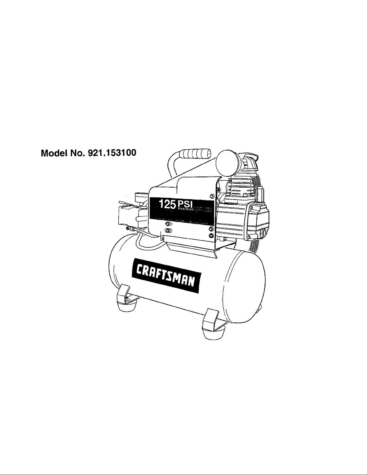
Owner’s Manual
CRRFTSMRN
AIR COMPRESSOR
3-gallon
1,5 HP (max developed)
1 HP Running
Oil Lubricated
CAUTION:
Before using this product,
read this manual and follow
all its Safety Rules and
Operating Instructions.
Sears, Roebuck and Co., Hoffman Estates, IL 60179 U.S.A.
WWW. sea rs.com/c raftsman
06/17/2004
Part No. El 00731
Safety Instructions
Installation & Operation
Maintenance & Storage
Troubleshooting Guide
Parts List
Español, p. 10
Page 2

TABLE OF CONTENTS
Warranty.............................................................................................................. below
Safety Instructions......................................................................................................... "I
Important Safety Instructions & Guideiines................................................................... 1
Specifications............................................................................................................... 2
Giossary........................................................................................................................ 2
Duty Cycie..................................................................................................................... 2
Parts & Features........................................................................................................... 3
installation & Assembiy................................................................................................. 4
Operating Procedures................................................................................................... 5
Page
Maintenance.................................................................................................................. 6
Storage.......................................................................................................................... 6
Troubleshooting Guide.................................................................................................. 7
Parts List........................................................................................................................ 8
Español........................................................................................................................... 10
Service Number................................................................................................ back cover
ONE YEAR FULL WARRANTY ON CRAFTSMAN AIR COMPRESSOR
if this Craftsman Air Compressor fails due to manufacturer's defects in material or workmanship
within one year of the date of purchase, RETURN IT TO THE NEAREST SEARS STORE OR
SERVICE CENTER IN THE UNITED STATES and it will be replaced or repaired {at our option),
free of charge.
If this Air Compressor is used for commercial or rental purposes, this warranty applies for only 90
days from the date of purchase. This warranty gives you specific legal rights and you may also
have other rights which vary from state to state.
Sears, Roebuck and Co., Dept. 817WA,
Hoffman Estates, IL 60179
Page 3

Safety Instructions
The information iisted below should be read and
understood by the operator. This information is given to
protect the user while operating and storing the air
compressor. We utilize the symbols below to allow the
reader to recognize important information about their
safety.
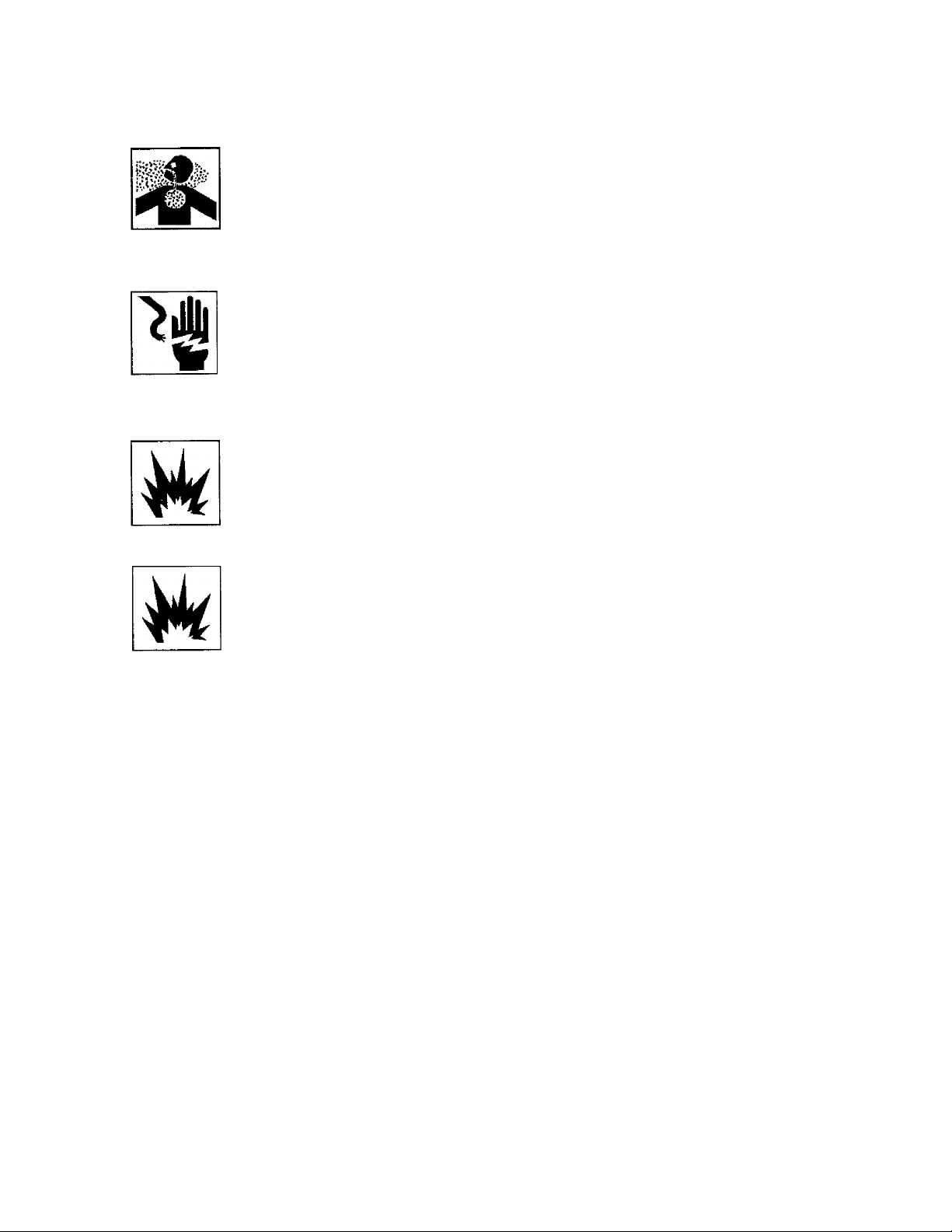
A DANGER
Indicates an imminently hazardous situation which, if not
avoided, will result in death or serious injury.
A WARNING
Indicates a potentially hazardous situation which, if not
avoided, could result in death or serious injury
Indicates a potentially hazardous situation which, if not
avoided, may result in minor or moderate injury.
When used without the safety alert symbol indicates a
potentially hazardous situation which, if not avoided, may
result in property damage.
A CAUTION
CAUTION
Important Safety Instructions and Guidelines
• Save all instructions
A WARNING
Improper operation or maintenance of this product could result in serious injury and/or property damage. Read and
understand all of the warnings and safety instructions provided before using this equipment. .
The air compressor should be operated on a dedicated 15 amp circuit. If the circuit does
not have 15 free amps available, a larger circuit must be used. Always use more air
hose before utilizing extension cords. All extension cords used must be 12 gauge with
a maximum length of 25 ft. The circuit fuse type must be a time delay. Low voltage could
cause damage to the motor.
Risk of Moving
Parts
If the air compressor is in operation, all guards and covers should be attached or
Installed correctly. If any guard or cover has been damaged, do not operate the
equipment until the proper personnel has correctly repaired the equipment. The power
cord should be free of any moving parts, twisting and/or crimping while in use and while
in storage.
Fiisk of Burns
Risk of Fallì
ing 1
Risk from
lying Objec
F
ts
There are surfaces on your air compressor that while in operation and thereafter can
cause serious burns if touched. The equipment should be allowed time to cool before
any maintenance is attempted. Items such as the compressor pump and the outlet tube
are normally hot during and after operation.
Operation of the air compressor should always be In a position that is stable. Never use
the air compressor on a rooftop or elevated position that could allow the unit to fail or
be tipped over. Use additional air hose for elevated jobs.
Always wear ANSI Z87.1 approved safety glasses with side shields when the air
compressor is in use. Turn off the air compressor and drain the air tank before
performing any type of maintenance or disassembly of the hoses or fittings. Never point
any nozzle or sprayer toward any part of the body or at other people or animals.
Page 4
Important Safety Instructions & Guidelines
Risk to Breathing
Risk of
Electrical Shock
Risk of
Explosion or Fire
Risk of Bursting
Avoid using the air compressor in confined areas. Always have adequate space
(12 inches) on all sides of the air compressor. Also keep children, pets, and others out
of the area of operation. This air compressor does not provide breathable air for anyone
or any auxiliary breathing device. Spraying material will always need to be in another
area away from the air compressor to not allow intake air to damage the air compressor
filter.
Never utilize the air compressor in the rain or wet conditions. Any electrical issues or
repairs should be performed by authorized personnel such as an electrician and should
comply with all national and local electrical codes. The air compressor should also have
the proper three prong grounding plug, correct voltage, and adequate fuse protection.
Never operate the compressor near combustible materials, gasoline or solvent vapors.
If spraying flammable materials, locate the air compressor at least 20 feet away from
the spray area. Never operate the air compressor indoors or in a confined area.
Always drain the air compressor tank daily or after each use. If the tank develops a leak,
then replace the air compressor. Never use the air compressor after a leak has been
found or try to make any modifications to the tank. Never modify the air compressor's
factory settings which control the tank pressure or any other function.
Specifications
Pump ..................................................Oil-lube direct drive
Motor Induction
Bore
...................................................
Stroke..................................................1.26"
Voltage Single Phase
..................................
..........................
1.5 HP max developed,
1HP running
1.65"
120 VAC
Glossary
CFM: Cubic feet per minute.
SCFM: Standard cubic feet per minute; a unit of measure
for air delivery.
PSIG: Pounds per square inch gauge; a unit of measure
for pressure.
ASME: American Society of Mechanical Engineers.
California Code: Unit may comply with California Code
462 (I) (2)/ (M) (2).
Cut-In Pressure: The air compressor will automatically
start to refill the tank when the pressure drops
beiow the prescribed minimum.
Duty Cycle
This is a 50% duty cycle air compressor. Do not run the air
could damage the air compressor.
Minimum Circuit Requirement ,.. .15 Amps
Air Tank Capacity ..............................3 Gallons
Cut-in Pressure
Cut-out Pressure................................125 PS I
SCFM @ 90 PSI
Cut-Out Pressure: The point at which the motor stops
when the tank has reached maximum air
pressure.
Code Certification: Products that bear one or more of
the following marks: UL, CUL, ETL, CSA, have
been evaluated by OSHA-certified independent
safety laboratories and meet the applicable
Underwriters Laboratories Standards for Safety.
compressor more than 30 minutes of one hour. Doing so
..................................
...............................
95 PS I
2.4
Page 5
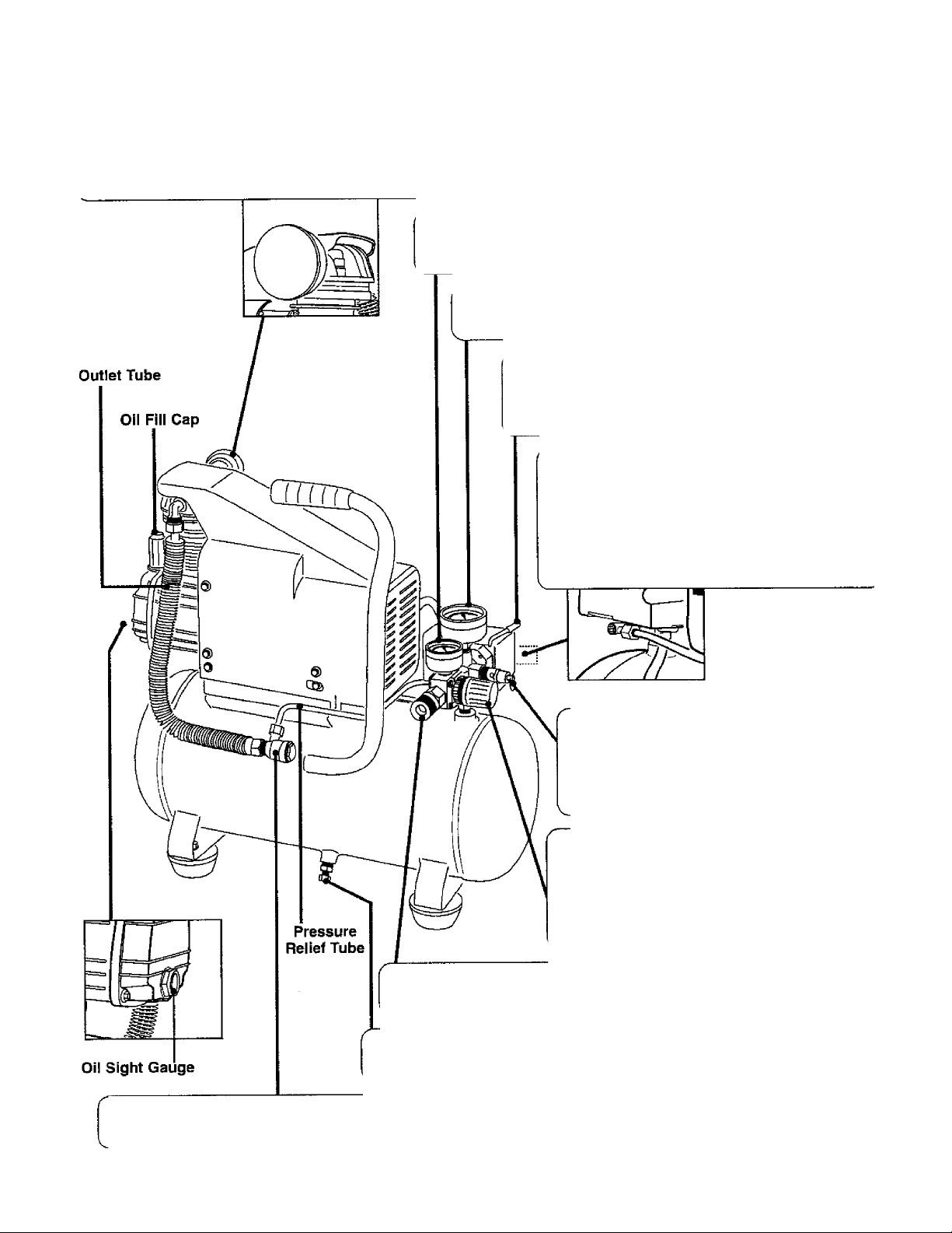
Parts & Features
See figures below tor reference.
Air Intake Filter , , , ^ ^ ^
Provides clean air to the pump and must always be kept free of debris. Check on a daily basis or before each use.
Regulator Gauge
Indicates the outgoing air pressure to the tool and is controlled
by the regulator.
Tank Pressure Gauge
indicates the reserve air pressure in the tank.
Pressure Switch
This controls the power to the motor and also the
cut-in/cut-out pressure settings. This switch serves
as the Auto-On/Off positions for the unit.
Pressure Relief Valve
The pressure relief vaive iocated on the
side of the pressure switch, is designed to
automatically release compressed air when
the air compressor reaches cut-out pressure.
The reieased air should only escape
momentarily and the valve should then close.
__________________
Tank Safety Valve
Used to allow excess tank pressure to
escape into the atmosphere. This valve
should only open when the tank pressure
is above the maximum rated pressure.
R^ulator
me air pressure coming from the air tank is
controlled by the regulator. To increase the
pressure turn the knob clockwise and to
decrease the pressure turn the knob
counterclockwise.
Quick Connect
Offers a quick release feature for attaching and removing the air hose.
Tank Drain Valve
Used to drain condensation from the air tank. Located at bottom of tank.
Check Valve . . , *
When the pump is not in operation the valve closes to retain air pressure inside the tank. An internal component.
Page 6
Installation & Assembly
A WARNING
The air compressor should be turned off and unplugged from
the power source before any maintenance is performed as
well as the air bled from the tank and the unit allowed time
to cool. Personal injuries could occur from moving parts,
electrical sources, compressed air or hot surfaces. The
regulator assembly must be attached before use. Failure to
assemble correctly could result in leaks and possible injury.
If unsure of assembly instructions or you experience difficulty
in the assembly please call your local service department for
further instruction.
Quick Connect Assembly
1. Before assembly be sure that the
Quick Connect (Q.C.) threads have a
sealant applied from the factory to prevent
leaks around the threads. If no sealant is
present, wrap the threaded portion with
Teflon tape.
2. Attach the Q.C. assembly to the air compressor by
aligning the Q.C. threads to the regulator on the manifold.
Be certain to align the threads before tightening to prevent
thread damage.
3. The assembly should turn clockwise 1 to 1.5 revolutions
after hand-tightening with a 13/16ths size wrench. To prevent
damage and leaks, do not
over-tighten.
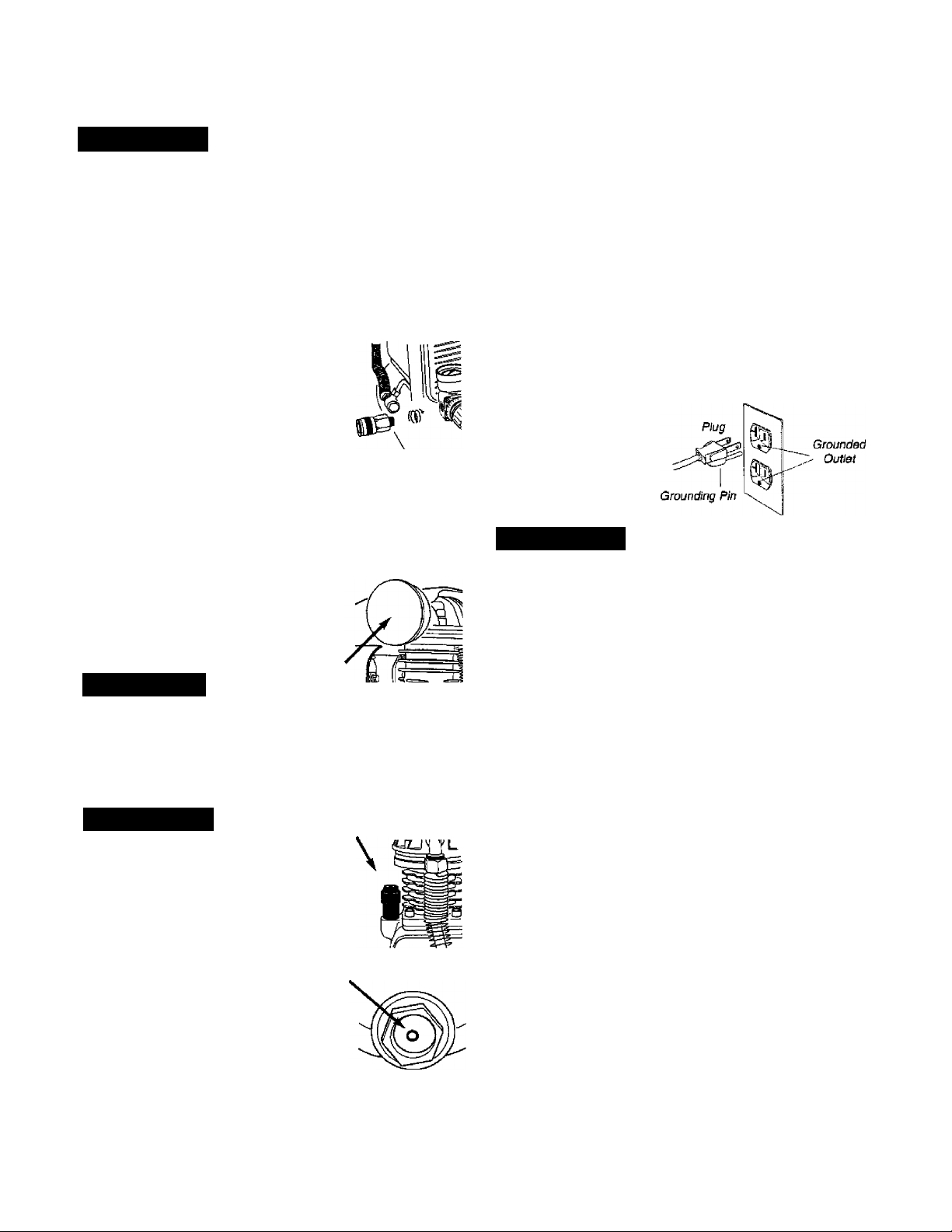
To Install the Air Intake Filter
Remove the air intake filter from the
poly bag and thread it onto the head
of the compressor as shown.
A CAUTION
Do not attempt to start the air compressor without first adding
oil to the crankcase. Serious damage can result unless filled
with oil. The pump is shipped without oil from the factory.
Only use non-detergent oils since multi-viscosity motor oils
leave carbon deposits on pump components, thus reducing
performance and compressor life.
A WARNING
Drain the tank to release all tank air
pressure before removing the oil fill cap.
Be sure the air vent in the oil fill cap {see
figure to the right) is free from debris.
If air vent is blocked, pressure can build
in crankcase causing damage to the
compressor and possible personal injury.
Lubrication and Oil
Remove the oil fill cap by turning it
counter-clockwise by hand. Fill the
compressor pump with an air compressor
oil such as SAE-30 non-detergent (API
CG/CD Heavy Duty) oil at slow intervals
until the oil reaches the center of the red
circle in the sight glass ( see figure above).
Use SAE-10 during extreme winter conditions.
Location of the Air Compressor
The air compressor should always be located in a clean,
dry, and well ventilated environment. The unit should have
at minimum, 12 inches of space on each side. The air fitter
intake should be free of any debris or obstructions. Check
the air filter on a daily basts to be sure it is clean and in
working order.
Grounding instructions
This product should be grounded. In the event of an electrical
short circuit, grounding reduces the risk of electric shock by
providing an escape wire for the electric current. This product
is equipped with a cord having a grounding wire with an
appropriate grounding plug. (See the figure below.) The plug
must be plugged into an outlet that is properly installed and
grounded in accordance with all local codes and ordinances.
Check with a qualified
electrician or service
personnel if these
instructions are not
completely understood
or if in doubt as to
whether the tool is
properly grounded.
A WARNING
improper installation of the grounding plug will result In a
risk of electric shock. If repair or replacement of the cord
or plug is necessary, do not oonnect the grounding wire to
either flat blade terminal. The wire with insulation having an
outer surface that is green with or without yellow stripes is
the grounding wire. Check with a qualified electrician or
serviceman if the grounding instructions are not completely
understood, or if in doubt as to whether the product is
property grounded. Do not modify the plug provided: if it
will not fit the outlet, have the proper outlet installed by a
qualified electrician.
This product is for use on a circuit having a nominal rating
of 120 volts and is factory-equipped with a specific electric
cord and plug to permit connection to a proper electric circuit.
Make sure that the product is connected to an outlet having
the same configuration as the plug. No adapter should be
used with this product. If the product must be reconnected
for use on a different type of electric circuit, qualified service
personnel should make the reconnection.
Extension Cords
Use only a 3-wire extension cord that has a 3-blade
grounding plug, and a 3-slot receptacle that will accept the
plug on the product. Make sure your extension cord is in
good condition. When using an extension cord, be sure to
use one heavy enough to carry the current your product will
draw. Cords must not exceed 25 feet and No. 12 AWG size
must be used. An undersized cord will cause a drop in line
voltage resulting in loss of power and overheating.
Break In Procedures
No break in procedure is required by the user. This
product is factory tested to ensure proper operation and
performance.
Page 7

Operating Procedures
Daily Start-Up Procedures
(l^ei the Auto-On/Off lever to the Off position.
/ZNCheck the air compressor visually for any damage
^or obstruction.
(^3J)Close the drain valve.
(^^heck the oil level of the pump.
rSi^Connect the air hose to the quick connect socket on
^the regulator assembly by inserting the quick connect
plug on the air hose into the quick connect socket. The
quick connect socket collar will snap forward and lock
the plug into place providing an air tight seal between
the socket and plug. To release the air hose push the
collar back on the quick connect socket.
(^Turn the Auto-On/Off lever to the On-Auto position and
the compressor will start and build air pressure in the
tank to cut-out pressure and then shut off automatically.
Adjust the regulator to a PS I setting that is needed for
^your application and be sure it is within the safety
standards required to perform the task, if using a
pneumatic tool, the manufacturer should have
recommendations in the manual for that particular
tool on operating PSI settings.
Note: The air compressor is now ready for use. The
following inflation and cleaning accessories packaged
with this unit should only be operated at maximum
pressure of 20-30 PSI: blow gun, tapered nozzle,
inflation needles, blow gun adapter.
Daily Shut-Down Procedures
1. Set the Auto-On/Off lever to the Off position.
2. Unplug the power cord from the receptacle.
3. Set the outlet pressure to zero on the regulator.
4. Remove any air tools or accessories. When draining
the tank, always use ear and eye protection. Drain the
tank in a suitable location; condensation will be present
in most cases of draining.
Open the drain valve allowing air to bleed from the
5.
tank. After all of the air has bled from the tank, close
the drain valve to prevent debris buildup in the valve.
A CAUTION
When draining the tank, always use ear and eye protection.
Drain the tank in a suitable location; condensation will be
present in most cases of draining.
A WARNING
Water that remains in the tank during storage will corrode
and weaken the air tank which could cause the tank to
rupture. To avoid serious injury, be sure to drain the tank
after each use or daily.
Page 8

Maintenance
NOTE: Any setvice procedure not covered in the maintenance schedule below should be performed by qualified service
personnel.
Items to Check/Change
Check Tank Safety Valve
Overall Unit Visual Check
Check Oil Level
Change Oil
Check Air Filter (more frequently in dusty or humid environments)
Drain Tank (after each use or daily)
A CAUTION
To ensure efficient operation and longer life of the air
compressor unit, a routine maintenance schedule should
be followed. The following schedule is geared toward a
consumer whose compressor is used in a normal working
environment on a daily basis. If necessary, the schedule
should be modified to suit the conditions under which your
compressor is used. The modifications will depend upon
the hours of operation and the working environment. Air
compressors used in an extremely dirty and/or hostile
environment will require a greater frequency of all
maintenance checks.
Before each
use or daily
X
X
X
X
X
After first
10 hours
X
Every
100 hours
X
A WARNING
The air compressor should be turned off and unplugged
from the power source before any maintenance is
performed as well as the air bled from the tank and the
unit allowed time to cool. Personal injuries could occur
from moving parts, electrical sources, compressed air or
hot surfaces.
Oil Changing
For changing the pump oil, be sure to do the foliowing:
1. Turn the unit off and unplug the power cord from the
receptacle.
2. Allow the compressor time to cool if it has been in
operation.
3. Open the drain valve to bleed all air from the tank.
4. Close the drain valve.
5. Remove the oil fill cap on the pump.
6. Remove the sight glass with a box end wrench or
socket. Drain the oil into a suitable container and
dispose of properly. The compressor may need to be
tipped slightly towards the drain hole to aiiow all of the
oil to drain.
Storage
For storing the air compressor, be sure to do the following:
1. Turn the unit off and unplug the power cord from the
receptacle.
2. Remove all air hoses, accessories, and air toois from
the air compressor.
3. Perform the daily maintenance schedule.
Reattach the sight glass. Note: Torque the sight glass
7.
10-12 inch lbs. when re-assembling. Be sure the gasket
is between the sight glass and the pump crankcase.
Refill the compressor pump with an air compressor oil
8.
such as SAE-30 non-detergent {API CG/CD Heavy
Duty) oil at slow intervals until the oil reaches the center
of the red circle in the sight glass. Use a SAE-10 during
extreme winter conditions.
4. Open the drain valve to bleed all air from the tank.
5. Close the drain valve.
6. Store the air compressor in a clean and dry location.
Page 9

Troubleshooting Guide
A WARNING
Personal injuries could occur from moving parts, electrical sources, compressed air, or hot surfaces.
PROBLEM
Air leaks at the check valve
or at the pressure relief valve.
Air leaks between head and
cylinder.
Air leak from safety valve.
Pressure reading on the
regulated pressure gauge
drops when an accessory is
used.
The air compressor should be turned off and unplugged from the power source before any
maintenance is performed as weii as the air bled from the tank and the unit allowed time to cool.
POSSIBLE CORRECTION
A defective check valve results in a constant air leak at the pressure relief valve
when there is pressure in the tank and the compressor is shut off. Drain the tank,
then remove and clean or replace the check valve.
Be sure of proper torque on head bolts. If leak remains, contact a service technician.
Operate the safety valve manually by pulling on the ring. If the valve continues to
leak when in the closed position, it should be replaced.
If there is an excessive amount of pressure drop when the accessory is used,
replace the regulator.
NOTE:
Adjust the regulated pressure under flow conditions (while accessory is being used).
It is normal for the gauge to show minimal pressure loss during initial use of the
tool.
Excessive tank pressure.
Motor will not start.
Excessive moisture in the
discharge air.
Air leaks from the tank body
or tank welds.
Move the Auto-On/Off lever to the Off position. If the unit doesn’t shut off, unplug it
from the power source and contact a service technician.
Make sure power cord is plugged in and the switch is on. Inspect for the proper size
fuse in your circuit box. If the fuse was tripped, reset it and restart the unit. If
repeated tripping occurs, replace the check valve or contact a service technician.
Remove the water In the tank by draining after each use. High humidity
environments will cause excessive condensation. Utilize water filters on your air
line.
NOTE:
Water condensation is not caused by compressor malfunction. Be sure the
compressor's air output is greater than your tool’s air consumption rate.
Never drill into, weld or othenvise modify the air tank or it will weaken. The tank can
rupture or explode. Compressor cannot be repaired. Discontinue use of the air
compressor.
Page 10

Craftsman Air Compressor Model 921.153100
Parts List
Page 11

Craftsman Air Compressor Model 921.153100
Parts List
Reference
Number
1 1
2 1
3
4
5
6
7
8
9
10
11 2
12
13 3
14
15
16
17 3
18 3
19
20
21
22
23
24 4
25
26
27
28 5
29
30 6
31
32
33
34
35
36
37
38
39
40
Kit
Number
2 Gasket, Head
2
2
3
3
3
3
3
3
4
5
2 Rubber Baffle
Part
Number
El 00434
El 00435
El 00227
El 00085
El 00228
El 00229
E100235
El 00248
El 00247
El 00955
El 00956
Description Quantity
Intake Fiiter Housing,
1/2 NPT (Kunsan)
Filter Element (Kunsan)
Head Bolt, M6x 1.0x30
Lock Washer, 6mm 8
Cylinder Head
Exhaust Elbow
Valve Plate
Valve Reed
Gasket, Valve Plate
Gasket, Cylinder Upper 1
Cylinder, ID42mm x H65mm 1
Bolt, M6x 1.0x20 5
Gasket, Cylinder Lower
Ring, Compression
Ring, Scraper
Piston
Piston Pin
Snap Ring, 12mm
Rod Connecting
Nut, M6X1.0
Eccentric
Oil Fill Cap
0 Ring, OD17mm x 2mm
Cover, Crankcase
Bolt, M5 xO.8 X15
Seal, Oil Sight Gauge
Oil Sight Gauge
Nut, M8X1.25 10
Washer, Flat 8mm
Screw, M3 X 0.5 X 6
Spring Washer, 3mm
Capacitor, Starting (200p F)
Capacitor, Running (40pF) 1
Crank Case
Motor
Cover, Motor Rear
Shroud
Pressure Relief Tube Assy
Reference Kit
Number Number
1 41
1
4
1
1
1
2
2
1
1
2
1
1
1
2
1
1
1
1
1
1
10
1
1
1
2
4
4
1
1
1
1
1
1
Not Shown
Not Shown El 00370
Not Shown
Not Shown El 00731 Manual, Operators/Parts
Note: Any part/kit number fieid without a number is not available.
Descriptions are provided for reference only. The Kit # coiumn represents
that the part being offered is avaiiabie in a kit. One of each part per kit wili
be offered.
Kit number and parts
Kit No.
Part
Number
El00957 Pressure Switch
42
43
44 El 00093
45
46
47 E100091
48
49
50
51
52
53
54 E100099
55
56 6
57 6
58
59
Part No.
1 El 00434
2
3
4 El 00087
5 El 00088
6
El 00959
E100251
E100102 Isolator Kit 30, 55-57
El 00594 Strain Reiief
El 00205
E100094
E100059
El 00595
El 00596
El 00097
E100098 Drain Valve, 1/4" NPT
6
E100101
El 00110
El 00859 Label, Warning Bilingual Tank
:hat are included are as follows;
Description Quantity
Pressure Guage, 2” 200PSi 1
Pressure Guage, 1.5” 200PSI
Safety Vaive
Reguiator 1
Coupler, Quick Connect
Nipple. 1/4" NPT X 27mm
Nipple, 1/4’ NPT X 80mm
Outlet Tube Assy
Grip. Handle
Tank 1
Check Valve
Flat Washer, 8mm
Isolator, Rubber
Bolt, M8 X 1.25mm x 20mm 4
Power Cord 14/3 x 6'
Bolt, MB x 1.25mm x 25mm
Label, Drain Tank Warning 1
Label, Specification HP, Tank size
Description Reference No.
Intake Filter Kit 1,2
Gasket Kit 7,10-11,14,29
Piston Kit 13,15-22
Oii Fill Cap w/O-ring 23-24
Oil Sight Gauge w/O-ring 27-28
1
2
1
1
1
1
1
1
1
1
1
16
4
1
4
1
1
1
Page 12

CONTENIDO
Página
Garantía ......................................................................................................... esta página
Instrucciones de seguridad............................................................................................. 11
instrucciones y pautas de seguridad importantes .......................................................... 11
Especificaciones ............................................................................................................ 12
Glosario........................................................................................................................... 12
Ciclo de trabajo .............................................................................................................. 12
Partes y características .................................................................................................. 13
Instalación y ensamblaje ................................................................................................ 14
Procedimientos de operación.......................................................................................... 15
Mantenimiento................................................................................................................. 16
Almacenamiento ............................................................................................................. 16
Diagnóstico y corrección de fallas
Lista de partes................................................................................................................... 8
.................................................................................
17
GARANTÍA DE UN AÑO SOBRE COMPRESOR DE AIRE CRAFTSMAN
Si este compresor de aire Craftsman llega a fallar debido a defectos de manufactura o de
materiales atribuibies al fabricante en un plazo de un año desde la fecha de compra, DEVUÉLVALO
A TIENDA O CENTRO DE SERVICIO SEARS MÁS CERCANO EN LOS ESTADOS UNIDOS
para que le sea reemplazado o reparado (a opción nuestra) sin ningún cargo.
Si este compresor de aire se usa con fines comerciales o de renta, esta garantía únicamente
aplica por 90 (noventa) días a partir de la fecha de compra. Esta garantía le da derechos legales
específicos; además, es posible que usted tenga otros derechos, los cuales varían según el
estado.
Sears, Roebuck and Co., Dept. 817WA,
Hoffman Estâtes, IL 60179
10
Page 13

Instrucciones de seguridad
Ei operador debe leer y entender la información
siguiente. Esta información se ofrece para proteger al
usuario durante la operación y el almacenaje dei
A PELIGRO
Indica una situación de riesgo inminente que, de no
evitarse, provocaría lesiones graves o la muerte.
A ADVERTENCIA
compresor. Los símbolos siguientes son los que se
utilizan para indicar ai lector información que es
importante para su seguridad.
indica una situación potencialmente peligrosa que, de no
evitarse, podría provocar lesiones menores o moderadas.
Indica una situación potencialmente peligrosa que, de no
evitarse, podría provocar lesiones graves o la muerte.
Al aparecer sin ei símbolo de alerta de seguridad,
indica una situación potencialmente peligrosa que, de no
evitarse, podría causar daños materiales.
Instrucciones y pautas de seguridad importantes
• Guarde todas las instrucciones •
A ADVERTENCIA
La operación y el mantenimiento inadecuados de este producto pueden provocar lesiones graves y daños materiales.
Antes de utilizar este equipo, lea y entienda las advertencias e instrucciones de seguridad aquí contenidas.
El compresor de aire se debe operar desde un circuito dedicado de 15 amperes. Si el
circuito no dispone de una capacidad de 15 amperes, se debe usar un circuito de mayor
capacidad. Si es necesario, antes de emplear una extensión eléctrica, añada una
manguera de aire más larga. Las extensiones eléctricas deben ser de calibre 12 y tener
una longitud máxima de 7.6 metros. El fusible del circuito debe ser de acción
retardada. Un voltaje demasiado bajo puede dañar ei motor.
go por pai
Ries
movimíen
1es en
to
Antes de operar el compresor, todos los protectores y cubiertas deben estar instalados
correctamente. Si alguno de los protectores o cubiertas está dañado, no opere el
equipo sino hasta que personal calificado repare el problema. El cable de corriente se
debe mantener alejado de las partes móviles del equipo y no debe torcerse ni
prensarse durante su empleo ni al ser almacenado.
Ríesg
o de quen
Riesgo de c
&
Riese|o de lanz£
de objeto
laduras
aida
imiento
s
En su compresor hay superficies que, de ser tocadas durante y después de su
operación, pueden causar quemaduras graves. Antes de darle mantenimiento al
equipo, se le debe dejar enfriar. Por lo normal, durante y después de su operación,
ciertas partes como la bomba del compresor y el tubo de salida estarán calientes.
El compresor siempre se debe operar en una posición estable. Nunca utilice el
compresor sobre un techo o en una posición elevada desde donde podría caer o
volcarse. Al trabajar en posiciones elevadas, utilice una manguera de aire más larga.
Al emplear el compresor, siempre utilice anteojos de seguridad con protectores
laterales que cumplan con la norma ANSI Z87.1. Antes de llevar a cabo cualquier clase
de mantenimiento y antes de desconectar las mangueras y acopladores, apague el
compresor y drene el tanque de aire. Nunca apunte la boquilla o rociador hacia
ninguna parte de su cuerpo ni del de otros seres.
11
Page 14

Instrucciones y pautas de seguridad importantes (œnt.)
Riesgo para la
respiración
Riesgo de
descargas eléctricas
Riesgo de
explosión y fuego
Riesgo de estallido
Evite utilizar e! compresor de aire en áreas encerradas. Siempre tenga un espacio libre
adecuado (30 cm.) en todos los lados del compresor. También mantenga fuera dei área
de operación a mascotas, niños y otras personas. Este compresor de aire no provee
aire que pueda ser respirado ni empleado con un dispositivo respiratorio
auxiliar. El material de rociado siempre deberá estar en otra zona, alejado del compresor
de aire, para evitar que el aire aspirado dañe el filtro del compresor.
Nunca utilice el compresor de aire bajo lluvia o en lugares mojados. Los problemas
eléctricos deben ser reparados por personal autorizado, tal como sería un electricista,
y deben cumplir con las normas eléctricas nacionales y locales. El compresor también
debe tener la clavija apropiada de tres terminales y contar con un suministro eléctrico
que sea del voltaje correcto y con un fusible de protección adecuado.
Nunca opere el compresor cerca de materiales combustibles, gasolina ni vapores de
solventes. Si está rociando materiales inflamables, coloque el compresor a una
distancia de cuando menos 6 metros del área de rociado. Nunca opere el compresor
de aire en interiores o en lugares cerrados.
Drene el compresor diariamente o después de cada utilización. Si el tanque tiene una
fuga, reemplace el compresor. No utilice el compresor si se ha detectado una fuga, ni
trate de modificar el tanque. Nunca modifique los ajustes de fábrica de! compresor que
controlan la presión del tanque y demás funciones.
Especificaciones
Bomb
............
inducción del motor......1.5 HP máximo desarrollado,
Diámetro..........................................................1.65"
Carrera.............................................................1.26"
Voltaje monofásico
De impulsión directa, lubricada con aceite
1 HP funcionando
.........................................
120 VAC
Capacidad mínima del circuito
Pies cúbicos X min, (SCFM) a 90 LPPC . , 2.4
Capacidad del tanque de aire
Presión de arranque........................................95 LPPC (PSi)
Presión de parada
Pies cúbicos X min. (SCFM) a 90 LPPC . , 2.4
..........................................
.......................
.........................
15 A
3 galones
125 LPPC (PSI)
Giosario
aCFM: Pies cúbicos por minuto.
SCFM: Pies cúbicos estándar por minuto; unidad de
medición de suministro de aire.
PSIG: Libras por pulgada cuadrada sobre la presión
atmosférica; unidad de medición de presión.
ASME: Sociedad estadounidense de ingenieros mecánicos.
Código de California: La unidad puede cumplir con el
código de California 462 (i) (2)/ (M) (2).
Presión de arranque: El compresor arranca
automáticamente cuando la presión baja a menos
del mínimo prescrito.
Presión de parada: Presión de aire que tiene que alcan
zarse en el tanque para que se detenga el motor.
Certificación de código: Los productos que tienen
alguna o varias de las siguientes marcas han sido
evaluados por laboratorios de seguridad
independientes certificados por OSHA, y cumplen
con las normas de seguridad de Underwriters
Laboratories: UL, CUL, ETL, CSA.
Ciclo de trabajo
Este compresor tiene un ciclo de trabajo de 50%. Nunca opere el compresor por más de 30 minutos cada hora. De
hacerlo, podría dañarlo.
12
Page 15

Partes y características
Como referencia, vea las figuras de abajo.
Filtro de aíre
Suministra aire limpio a la bomba. Siempre se le debe tener libre de suciedad. Revíselo diariamente o antes de
cada uso. (Véase ia imagen en la sección de ensamblaje.
Manómetro depresión de salida
Indica la presión de salida dei aire que se entrega a la herramienta,
presión que es controlada por el regulador.
Manómetro de presión del tanque
Indica ia presión de la reserva de aire del tanque.
Interruptor de presión
Controla el suministro eléctrico al motor y también los
ajustes de presión de arranque y presión de parada.
Este interruptor sirve como posición de autoencendido
y apagado {Auto-On/Off) de la unidad.
Válvula de alivio de presión
Esta válvula, que se encuentra en el costado
del interruptor de presión, está diseñada para
liberar aire comprimido de manera automática
cuando el compresor llegue a la presión de
parada. El aire sólo deberá escapar durante
un instante, cerrándose la válvuia en seguida.
Válvula de seguridad del tanque
Permite que el exceso de presión en el
tanque escape al medio ambiente. Esta
válvula sólo se abrirá cuando la presión
en el tanque esté por encima de la presión
máxima nominal del modelo,
V .
-------------
^
I I a I .1 .11 I
Regulador
La presión del aire que saie del tanque es
controlada por el regulador. Para aumentar
la presión, gire la perilla en dirección de las
manecillas; para disminuirla, gire ia perilla en
dirección contraria a las manecillas.
Conector de acoplamiento rápido
Permite conectar y desconectar rápidamente la manguera de aire.
Válvula de drenado
Sirve para drenar la condensación acumulada en el fondo del tanque. Se encuentra
Visor de aceite
en la parte inferior del tanque.
Válvula de retención
Cuando la bomba no está en operación, esta válvula se cierra para retener la presión de aire dentro del tanque.
Es un componente interno.
------------------------------------------------------------------------------------i3----------------------------------------------------------------------------------------
Page 16

Instalación y ensamblaje
A ADVERTENCIA
Antes de dar mantenimiento al compresor de aire, se le debe
apagar y desconectar de la fuente de poder, además de purgar
el aire del tanque y darle suficiente tiempo para enfriarse, Existe
el riesgo de que las parles móviles, la fuente eléctrica, el aire
comprimido y las superficies calientes provoquen lesiones. El
ensamble del regulador debe estar Instalado antes de usar el
compresor. Un ensamblaje inadecuado puede ser causa de
fugas y posiblemente de lesiones. Si no entiende las instruc
ciones de ensamblaje o tiene dificultad para llevar a cabo el
armado, por favor llame a su departamento local de servicio.
Conjunto de conexión rápida
1. Antes de ensamblar, compruebe que
se haya aplicado de fábrica un sellador
a la rosca del conector rápido, con el fin 11'
de evitar fugas por esa zona. Si no hay
sellador, enrolle la parte roscada con cinta de teflón.
2. Conecte el conjunto de conexión rápida al compresor de
aire, alineando la rosca del conector rápido con el regulador
en el colector. Para evitar daños a las roscas, asegúrese de
alinearlas correctamente antes de roscarlas.
3. El conjunto se debe apretar a mano en dirección horaria
y luego apretar de 1 a 1.5 vueltas con una llave de 13/16”.
Para evitar daños y fugas, no apriete demasiado.
w/\
Instalación del filtro de aire
Saque e! filtro de aire de entrada de la
bolsa de poliuretano y enrósquela en el
cabezal de la compresora, como se muestra.
A PRECAUCION
añadir aceite al depósito. De no llenarlo de aceite y seguir el
procedimiento de operación, el compresor podría sufrir daños
graves. La bomba sale de la fábrica sin aceite. En el depósito
queda una pequeña cantidad de aceite, sobrante de las prue
bas en la fábrica. Sólo use aceite no detergente, pues los
aceites multigrado para motor dejan depósitos de carbón en los
componentes de la bomba, reduciendo el desempeño y la vida
del compresor.
aire sin antes
A ADVERTENCIA
Antes de quitar el tapón de llenado de aceite,
drene el tanque para liberar la presión de aire.
Compruebe que el respiradero del tapón de
llenado de aceite esté limpio (vea la
ilustración). Si está bloqueado, puede haber
una acumulación de presión en el depósito,
dañando el compresor y posiblemente
causando lesiones al operador.
Lubricación y aceite
Quite el tapón de llenado de aceite girándolo
con la mano en dirección contraria a las
manecillas. Llene lentamente la bomba del
compresor con aceite para compresor de aire
como aceite SAE-30 no detergente (APt
CG/CD de trabajo pesado) hasta que llegue al
centro del círculo rojo del visor, como se
muestra en la imagen. En condiciones extremas
de invierno use aceite SAE-10.
Ubicación del compresor de aire
El compresor de aire siempre debe estar en un medio ambiente
limpio, seco y bien ventilado. La unidad debe tener cuando
menos 30 cm, de espacio libre en cada lado. La toma del filtro
de aire debe estar libre de suciedad y obstrucciones. Por favor
revise diariamente el filtro de aire para comprobar que esté
limpio y en correcto estado de funcionamiento.
Instrucciones de conexión a tierra
Este producto se debe conectar a tierra. En caso de
cortocircuito, la conexión a tierra reduce el riesgo de descargas
eléctricas al ofrecer un alambre de escape para la corriente
eléctrica. Este producto cuenta con un cable que tiene un alambre
de tierra y una clavija con terminal de tierra. La clavija debe
enchufarse en un tomacoriiente instalado y puesto a tierra según
las normas locales. Hable con un electricista o agente de servicio
calificado si no entiende
completamente estas
instrucciones, o si tiene
dudas sobre la correcta
puesta a tierra de
la herramienta.
A ADVERTENCIA
Una conexión a tierra inadecuada puede provocar una
descarga eléctrica. Si necesita reparar o cambiar el cable
o la clavija, no conecte el alambre de tierra a ninguna de las
terminales planas. El alambre de tierra es el de color verde,
con o sin franjas amarillas. Si no entiende completamente las
instrucciones de conexión a tierra, o si tiene dudas sobre la
correcta puesta a tierra de la herramienta, hable con un electricista
o agente de servicio calificado. No modifique la clavija que viene
con el equipo; si no puede enchufarla en el tomacorriente, llame
a un electricista para que cambie ei tomacorriente.
Este producto está diseñado para trabajar en un circuito con
un voltaje nominal de 120 volts y está dotado de fábrica con un
cable y clavija que permiten su conexión a un circuito eléctrico
apropiado. Asegúrese de que el producto esté conectado a un
tomacorriente con la misma configuración que la clavija. No se
debe usar un adaptador con este equipo. Si se debe conectar el
equipo a un circuito eléctrico de diferente tipo, consiga la ayuda
de personal calificado.
Extensiones eléctricas
Sólo utilice una extensión eléctrica de tres alambres con
una clavija aterrizada de tres terminales que pueda enchufarse
en un tomacorriente de tres orificios. Asegúrese de que su
extensión eléctrica esté en buenas condiciones. Si utiliza una
extensión, compruebe que sea de la capacidad de corriente que
requiere su equipo. Las product is factory tested to ensure prop
er operation and performance.
Procedimiento inicial de preparación
No se requiere un procedimiento inicial de preparación.
Este producto ha sido probado en la fábrica para asegurar su
operación y desempeño adecuados.
14
Page 17

Procedimientos de operación
Procedimiento diario de arranque
(^Ponga el interruptor Auto-On/Off en la posición de
apagado (Off).
(^Compruebe visuaímente que el compresor no tenga
daños ni obstrucciones.
@Cierre la válvula de drenado.
(X)Revise el nivel de aceite de la bomba.
(^Enchufe la manguera de aire al conector de
acoplamiento rápido de ia unidad del regulador. El
collarín del conector de acoplamiento rápido saltará
para adelante, sujetando el enchufe y efectuando un
sello entre el conector y el enchufe. Para desconectar
la manguera de aire, empuje hacia atrás el collarín del
conector de acopiamiento rápido.
(^6)Enchufe el cable de corriente en un tomacorriente
Mueva el interruptor Auto-On/Offa la posición de
encendido {Auto-On)', el compresor deberá arrancar,
acumulando presión de aire en el tanque hasta llegar
a la presión de apagado, momento en el cual se
apagará de manera automática.
(^Ajuste e! regulador a la presión de aire recomendada
para su aplicación, cerciorándose de que está dentro
de las normas de seguridad para llevar a cabo la
tarea. En el caso de herramientas neumáticas, el
manual del fabricante debe tener recomendaciones
sobre su presión de operación.
Nota: Ahora e! compresor de aire está listo para ser
usado. Los siguientes accesorios de inflado y limpieza,
los cuales vienen con esta unidad, sólo se deben
operar a una presión máxima de 20-30 PSI: soplete
(y su adaptador), boquilla cónica, agujas de inflado.
Procedimiento diario de apagado
1. Ponga el interruptor en la posición de apagado (Off).
2. Desconecte el cable del tomacorriente.
3. Ponga en cero el regulador de presión de salida.
4. Desconecte las herramientas y accesorios. Siempre
use protección para oídos y ojos al drenar el tanque.
Drene el tanque en un lugar adecuado; en casi todos
los casos habrá presencia de condensación en el
drenaje.
5. Abra la válvula de drenado permitiendo que escape el
aire del tanque. Cuando haya salido del tanque todo e!
aire, cierre la válvula de drenado para evitar que le
entre suciedad.
Al drenar el tanque utilice protección para oídos y ojos.
Drene el tanque en un lugar apropiado; en la mayoría de
tas ocasiones al drenar saldrá condensación.
A ADVERTENCIA
Si no drena el tanque, en su interior quedará agua que lo
corroerá y debilitará, lo cual puede provocar su ruptura.
Siempre drene el tanque diariamente o después de cada
uso.
15
Page 18

Mantenimiento
NOTA: Cualquier procedimiento de servicio que no esté cubierto en el programa de mantenimiento que sigue deberá
ser efectuado por personal de servicio calificado.
Tras las
primeras
10 horas
Cada
100 horas
Puntos a revisar o cambiar
Antes de cada
uso 0 diaria
mente
Revisar la válvula de seguridad del tanque
Revisar visualmente el aspecto general de la unidad
Revisar el nivel de aceite
Cambiar el aceite
Revisar el filtro de aceite (con mayor frecuencia si se trabaja en
ambientes polvosos o húmedos)
Drene el tanque (cada vez que sea usado o diariamente)
A fin de asegurar una operación eficiente y una larga
vida del compresor, debe seguirse un programa de
mantenimiento de rutina. El siguiente programa de
mantenimiento está enfocado al consumidor cuyo
compresor es usado en un medio ambiente normal y con
una periodicidad diaria. De ser necesario, el programa se
debe modificar para adecuarlo a las condiciones bajo las
cuales se usará su compresor. Los compresores em
pleados en medios ambientes muy sucios u hostiles
requerirán mantenimiento más frecuente.
Cambio de aceite
El procedimiento para cambiar el aceite de la compresora
es el siguiente:
1. Apague ei compresor y desenchufe ei cable de
corriente.
2. Si el compresor ha estado en operación, permita que
se enfríe.
3. Abra la válvula de drenado para vaciar el aire del
tanque.
4. Cierre la válvula de drenado.
5. Quite el tapón de llenado de aceite que se encuentra
en la bomba.
6. Quite el visor con una iiave de tuercas o de cubo.
Deje que drene el aceite en un recipiente adecuado y
deseche este contenedor de manera apropiada. Tal
vez haya que inclinar el compresor ligeramente hacia
adelante para que salga todo el aceite.
X
X
X
X
X
X
X
A ADVERTENCIA
Antes de dar mantenimiento ai equipo, se le debe apagar
y desconectar del tomacorriente, así como purgar el aire
del tanque y permitir que la unidad se enfríe. Las partes
en movimiento, las fuentes eléctricas, el aire comprimido
y las superficies calientes pueden provocar lesiones.
7. Vuelva a colocar el visor. NOTA: apriete el visor a un
par de apriete de 10 a 12 libras-pulgada. Revise
también la colocación del empaque entre el visor y el
cárter del compresor.
8. Llene lentamente la bomba del compresor con aceite
para compresor de aire, como aceite SAE-30 no
detergente (API CG/CD de trabajo pesado) hasta
que llegue al centro del círculo rojo del visor. En
condiciones de invierno extremas use aceite SAE-10.
Almacenamiento
Para almacenar el compresor, asegúrese de hacer lo siguiente:
1. Lleve a cabo el programa de mantenimiento de rutina.
2. Apague la unidad y desconecte del tomacorriente la
clavija.
3. Quite del compresor las mangueras, accesorios y
herramientas de aire.
4. Abra la válvula de drenado para drenar el aire del
tanque.
5. Cierre la válvula de drenado.
6. Guarde el compresor en un lugar limpio y seco.
16
Page 19

Diagnóstico y corrección de fallas
A ADVERTENCIA
movimiento, las fuentes eléctricas, el aire comprimido y las superficies calientes pueden provocar lesiones.
PROBLEMA
Fuga de aire en la válvula de
retención o en la válvula de
alivio.
Fugas de aire entre la cabeza
y el cilindro.
Fuga de aire en la válvula
de seguridad.
La presión indicada en el
manómetro de presión
Antes de dar mantenimiento ai equipo, se le debe apagar y desconectar del tomacorriente,
así como purgar el aire del tanque y permitir que la unidad se enfríe. Las partes en
POSIBLE CORRECCIÓN
Una válvula de retención defectuosa provoca una fuga de aire constante en la
válvula de alivio cuando está apagado el compresor teniendo presión de aire.
Drene el tanque y quite y limpie o cambie la válvula de retención.
Compruebe el apriete de los pernos de la cabeza. Si continúa la fuga, llame a
un técnico de servicio.
Opere manualmente la válvula de seguridad tirando del anillo. Si el tanque continúa
teniendo una fuga estando la válvula en posición cerrada, ésta deberá ser cambiada.
Si al usar un accesorio hay una caída excesiva de presión,
cambie el regulador, regulada cae al usar un accesorio.
1 NOTA
Ajuste la presión regulada bajo condiciones de flujo (mientras se utiliza un
accesorio). Es normal que el manómetro indique una caída de presión
mínima al comenzar a utilizar la herramienta.
Presión excesiva
en el tanque.
El motor no arranca.
Humedad excesiva en el
aire de salida.
Fugas de aire en el cuerpo
0 la soldadura del tanque.
Apague el interruptor de encendido. Si la unidad no se apaga, desconéctela de!
tomacorriente y comuniqúese con un técnico de servicio.
Compruebe que el cable de corriente está enchufado y que el interruptor está
encendido. Compruebe que el fusible de la caja de circuitos sea de la capacidad
adecuada. Sí se ha disparado, restablézcalo y rearranque la unidad. Si el fusible se
dispara con frecuencia, revise la válvula de retención o llame a un técnico de servicio.
Saque et agua del tanque drenándolo después de cada vez que se use. En los
medios ambientes de alta humedad habrá un exceso de condensación; instale
filtros de agua en su línea de aire.
1 NOTA
La condensación no es provocada por una falla en el compresor. Compruebe que la
salida de aire del compresor sea mayor que el consumo de aire de su herramienta.
Nunca taladre, suelde o modifique de ninguna manera el tanque, pues se
debilitará. El tanque podría romperse o explotar. El tanque no puede ser
reparado. Ya no utilice el compresor de aire.
17
Page 20

Get it fixed, at your home or ours!
Your Home
For repair - in your home - of all major brand appliances,
lawn and garden equipment, or heating and cooling systems,
no matter who made it, no matter who sold it!
For the replacement parts, accessories and
owner's manuals that you need to do-it-yourseif.
For Sears professional installation of home appliances
and items like garage door openers and water heaters.
1 -800-4-M Y- HOME® (i -800-469-4663)
Call anytime, day or night (U.S.A. and Canada)
www.sears.com www.sears.ca
Our Home
For repair of carry-in items like vacuums, lawn equipment,
and electronics, call or go on-line for the location of your nearest
Sears Parts & Repair Center.
1-800-488-1222
Call anytime, day or night (U.S.A. only)
www.sears.com
To purchase a protection agreement on a product serviced by Sears:
1 -800-827-6655 (U.S.A.) 1 -800-361 -6665 (Canada)
Para pedir servicio de reparación
a domicilio, y para ordenar piezas:
1-888-SU-HOGAR®“
(1-888-784-6427)
® Registered Trademark/ ™ Trademark/“Service Mark of Sears, Roebuck and Co.
® Marca Registrada/ ™ Marca de Fábrica/ “ Marca de Servicio de Sears, Roebuck and Co.
“ Marque de commerce/ “ Marque déposée de Sears, Roebuck and C(5.
Au Canada pour service en français:
1-800-LE-FOYER«^
(1-800-553-6937)
www.sears.ca
© Sears, Roebuck and Co.
 Loading...