

Page 1

OWNER'S MANUAL
CRQFTSMPN
V Im n r I ^ 1*1 n 11,
7.5 Horsepower
2700 PSI 3 GPM
High Pressure Washer
Model No:
919.7627Q0
h
'h
\
WARNING: Before using this
product, read this manual
and follow all Safety Rules
and Operating Instructions.
Sears, Roebuck and Co., Hoffnnan Estates, IL 60179 U.S.A.
MGP-782700 l/S/aS
Safety
• Assembly
• Operation
• Maintenance
• Parts List
• Español
Page 2

TABLE OF CONTENTS
.........
Warranty
Safety Guidelines
Assembly
Operation
Maintenance
..................................
.....................
...
.................................
.................................
........................
.
.
.
.
Service and Adjustments.............
.
2
.........
3-5 Troubleshooting
.
........
5-7
.........
7-10 EPA Codes...
.
........
11-13
.........
14 Español
LIMITED ONE YEAR WARRANTY ON CRAFTSMAN HIGH PRESSURE WASHER
For one year from the date of purchase, when this Craftsman High Pressure Washer is main
tained and operated according to the instructions in the owner’s manual. Sears will repair, free of
charge, any defect in material and workmanship.
Storage......................
.........................................
Parts
........................
.....................
How to Order Parts
....
..........................
.
.
......
....................
.
.................16-30
...........
.
.......
.
.
................
.....31-32
Back Cover
..14
15
34-52
If your Craftsman Pressure Washer is used for commercial or rental purposes, this warranty
applies only for 90 days from the date of purchase.
LIMITED ONE YEAR WARRANTY ON CRAFTSMAN ENGINE
For one year from the date of purchase, when this Craftsman engine is maintained and operated
according to the instructions in the owner’s manual, Sears will repair, free of charge, any defect
in material and workmanship.
If your Craftsman engine is used for commercial or rental purposes, this warranty applies only
for 90 days from the date of purchase. This warranty does not cover: Expendable items such as
spark plugs and air filters, which become worn during normal use.
Repairs necessary because of operator abuse or negligence, including damage resulting from
no water being supplied to pump or failure to maintain the equipment according to the instruc
tions contained in the owner's manual, are not covered under warranty.
WARRANTY SERVICE IS AVAILABLE BY RETURNING THE HIGH PRESSURE WASHER TO THE
NEAREST SEARS SERVICE CENTER/DEPARTMENT THROUGHOUT THE UNITED STATES.
This, warranty gives you specific legal rights and you may also have other rights, which vary
from state to state.
Sears, Roebuck and Co., D/817 WA, Hoffman Estates, IL 60179
Page 3

SAFETY GUIDELINES - DEFINITIONS
This manual contains information that is important for you to know and understand. This information relates to protecting
YOUR SAFETY and PREVENTING EQUIPMENT PROBLEMS. To help you recognize this information, we use the symbols
below. Please read the manual and pay attention to these sections. SAVE THESE DEFINITIONS/INSTRUCTIONS.
A WARNING indicates a potentially hazardous
situation which, if not avoided, could result in
death or serious iniurv.
A CAUTION indicates a potentially hazardous situation
A DANGER indicates an imminently hazardous
situation which, if not avoided, wH] result in
death or serious Iniurv.
injury-
which, if not avoided, mav result in minor or moderate
IMPORTANT SAFETY INSTRUCTIONS
AWARNING
Improper operation or maintenance of this product could result in serious injury and property damage. Read
and understand all warnings and operating instructions before using.
tO/2/97
HAZARD
A DANGER
RISK OF EXPLOSION
OR FIRE
WHAT CAN HAPPEN
Spilled gasoline and its vapors can
become ignited from cigarette
spari<s, electrical arcing, exhaust
gases, and hot engine components
such as the muffler.
Heat will expand fuel in the tank
which could result in spillage and
possible fire explosion.
Operating the pressure washer in an
explosive environment could result
in a fire.
• Materials placed against or near the
pressure washer can interfere with
its proper ventilation features
causing overheating and possible
ignition of the materials.
* Improperly stored fuel could lead to
accidental ignition. Fuel improperiy
secured could get into the hands of
children or other unqualified persons.
HOWTO PREVENT IT
Shut off engine and allow it to cool
before adding fuei to the tank.
Use care in filling tank to avoid
spilling fuel. Move pressure washer
away from fueling area before
starting engine.
Keep maximum fuel level Vz" below
top of tank to allow for expansion.
Operate and fuel equipment in well
ventilated areas free from obstruc
tions. Equip areas with fire
extinguishers suitable for gasoline
fires.
Never operate pressure washer In an
area containing dry brush or weeds.
Store fuel in container approved for
gasoline, in a secure location away
from work area.
ADANGER
RISK TO BREATHING
Breathing exhaust fumes will cause
serious injury or death.
Some cleaning fluids contain sub
stances which could cause injury to
skin, eyes, or lungs.
Operate pressure washer in a well
ventilated area. Avoid enclosed areas
such as garages, basements ,etc.
Never operate unit in a location
occupied by humans or animals.
Use only cleaning fluids specifically
recommended for high pressure
washem. Follow manufacturers
recommendations.
Page 4

IMPORTANT SAFETY INSTRUCTIONS (conrd)
HAZARD
WHAT CAN HAPPEN
HOWTO PREVENT IT
^WARNING
RISK OF UNSAFE
OPERATION
Awarning
RISK OF INJURY FROM
SPRAY
• Unsafe operation of your pressure
washer could lead to serious injury
or death to you or others.
• The spray gun/wand is a powerful
cleaning tool that could look like a
toy to a child.
Reactive force of spray will cause
gun/wand to move, and could cause
the operator to slip or fall, or
misdirect the spray, improper control
of gun/wand can result in injuries to
self and others.
* High velocity fluid spray can cause
objects to break, propelling particles
at high speed.
• Light or unsecured ot^ects can become
hazardous projectiles.
Become familiar with the operation
and controls of the pressure washer.
Keep children away from the
pressure washer at all times.
Never defeat the safety features of this
product.
Do not operate machine with missing,
broken, or unauthorized parts.
Never leave wand unattended while
unit is running.
Keep work area free of obstacles.
Stand on a stable surface and grip gun/
wand firmly. Expect the gun to kick
when triggered.
Always wear ANSI approved Z87 safety
glasses. Wear protective clothing to
protect against accidental spraying.
Never point wand at, or spray people or
animals.
Always secure trigger lock when wand
is not in service to prevent accidental
operation.
Never permanently secure trigger in pull
back (open) position.
Awarning
RISK OF
ELECTRICAL
SHOCK
Awarning
RISK OF FLUID INJECTION
Awarning
RISK OF CHEMICAL BURN
Spray directed at electrical outlets or
switches, or objects connected to an
electrical circuit, could result in a fata!
electrical shock.
• Your washer operates at fluid
pressures and velocities high enough
to penetrate human and animal flesh,
which could result in amputation or
other serious injury. Leaks caused by
loose fittings or worn or damaged
hoses can result in injection injuries.
DO NOT TREAT FLUID INJECTION AS
A SIMPLE CUT! See a physician
immediately!
* Relieve system pressure before
attempting maintenance or disassem
bly of equipment.
Use of acids, toxic or corrosive
chemicals, poisons, insecticides, or
any kind of flammable solvent with this
product could result in serious injury
or death.
Unplug any electrically operated
product before attempting to clean it.'
Direct spray away from electric outlets
and switches.
Never place hands in front of nozzle.
Direct spray away from self and others.
Make sure hose and fittings are
tightened and in good condition. Never
hold onto the hose or fittings during
operation.
Do not aliow hose to contact muffler.
Never attach or remove wand or hose
fittings while system is pressurized.
Use only hose and high pressure
accessories rated for 2000 PSI service.
To relieve system pressure, shut off
engine, turn off water supply, and pull
gun trigger until water stops flowing.
• Do not use acids, gasoline, kerosene, or
any other flammable materials in this
product. Use only household
detergents, cleaners and degreasers
recommended for use in pressure
washers.
* Wear protective clothing to protect
eyes and skin from contact with
sprayed materials.
________________
Page 5
HAZARD
IMPORTANT SAFETY INSTRUCTIONS (cont’d)
WHAT CAN HAPPEN
HOWTO PREVENT IT
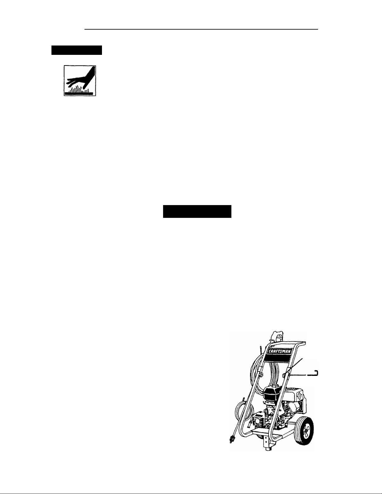
Awarning
RISK OF HOT SURFACES
Contact with hot surfaces, such as
engines exhaust components, could
result in serious bum.
• During operation, touch only the control
surfaces of the pressure washer. Keep
children away from the pressure washer
at all times. They may not be able to
recognize the hazards of this product.
IMPORTANT:
The powerful spray from your pressure washer is capable of causing damage to fragile surfaces such as: wood, glass,
automobile paint, auto stripping and trim, and delicate objects such as flowers and shrubs. Before spraying, check the
item to be cleaned to assure yourself that it is robust enough to resist damage from the force of the spray. Avoid the
use of the concentrated spray stream except for very strong surfaces like concrete and steel.
Operating unit with water supply shut off without flow of water will result in equipment damage. You should never run
this pressure washer for more than 2 minutes without pulling the trigger to allow cool water to enter the pump and the
heated (recirculated) water to exit. Running the pressure washer with water supply shut off will void your warranty.
ASSEMBLY
Carton Contents
• Main Unit pressure washer with wheels
• Handle
• High Pressure Hose
• Chemical Pickup Hose and Filter
• Bag Containing
Video Cassette
Owners’ Manual
Nozzzle Cleaning Kit and Replacement 0-Rings
~ Rubber Isolator and Mounting Hardware
• Box Containing
Gun
Wand
Engine Oi!
Handle Mounting Hardware
Tools Required for Assembly
Adjustable wrench
1/2” Socket wrench
Remove Pressure Washer from Carton
NOTE: The high pressure and chemical hose are
located at the bottom of the box.
Preparing the Pressure Washer for First Use
• Note; Included with your pressure washer is a video
tape on how to prepare your unit for operation. It is
recommended you view this tape before performing
the next steps.
1. * Insert handle onto frame,
• Slide J bolts into frame.
• Tighten knobs turning in clockwise direction.
(Tighten lutob in etocfewis«
(Krectìon to ttiTMCiatf «ntf of 4 bolt}
4 boK hot«. Thmsdod otid
goes b) botttHO hole}
• Open box from the top. Locate and remove from
box, the parts box, which includes gun, handle,
wand,oil, knobs and J bolts. Next remove the parts
bag and the handle.
• Cut carton along dotted lines.
• Remove all carton inserts.
Page 6

Remove wood plank from the frame of the unit.
2.
An adjustable wrench is required. Discard nut,
bolt and board.
3. • Mount the rubber isolator to the frame. To mount
isolator place threaded end of bolt through the
washer. Next with washer on bolt place threaded
end of bolt through the rubber isolator. Place
threaded portion of isolator through the same
hole location the wood plank was mounted to on
the pressure washer Next place lockwasher
over threaded portion of nut that has been
placed through
'Me mounting hole in the pressure
washer and use nut to tighten isolator to the
frame. Tighten nut with an adjustable wrench. All
isolator parts are supplied In parts bag.
7. • Connect high pressure hose to the quick connect
outlet on pressure washer.
QUICK CONNECT
OUTLET
NOTE: Keep hose away from engine muffler.
8. • Place assembled gun and wand on pressure
washer holder.
NUT
PRES^RE
W>^HER
FRMIE
Connect wand with nozzle extension to gun. To
4,
LOCKWASHER
r-C
^^^ISOLATOfl
BOLT—
tighten, turn knob in clockwise direction. Hand
tighten.
5. • Cut tie wrap off of high pressure hose. Unwind
high pressure hose to attach the threaded end to
the gun.
NOTE: Do not remove Telfon tape on threads.
6. • Connect chemical hose to the chemical injector
nipple on the pump.
NOTE: Your unit’s pump is shipped with a
temporary plug that must be replaced with a
breather cap. This plug is located over the pump’s
oil port. Unscrew and remove this plug. Remove
the breather cap from the bag attached to the plug
and install it in the pump’s oil port.
8NEATHER
CAP
A CAUTION; Failure to replace the plug will res
in serious pump damage.
m
Page 7

Checklist
Before going any further please review the following:
♦ Be sure you have completed assembly instruction.
• Double check all fittings to be sure they are tight.
IMPORTANT: Before any attempt to start your pres
sure washer be sure to check engine oil (See Operation
under Engine Oil, page 9.)
OPERATION
Know Your High Pressure Washer
Read this Owner^s Manual and Safety Rules before
operation of your High Pressure Washer Compare
this illustration with our pressure washer to familiarize
yourself with the location of various controls and
adjustments. Save this manual for future reference.
PUMP- Develops high pressure.
ENGINE OIL. FILL- Place where engine oil is poured.
PRESSURE REGULATOR- Allows you to adjust the
pressure of the outlet stream.
ENGINE RUN/STOP SWITCH- Sets engine in starting
mode for recoil starter — Stops running engine.
CHOKE
LEVER
RECOIL STARTER- Used for starting the engine
manually.
SPRAY GUN ASSEMBLY- Controls the application of
water onto cleaning surface with trigger device.
PUMP OIL FILL- Port where pump oil is poured and
breather cap is located.
GAS TANK/CAP- Cap is removed and unleaded
gasoline is poured.
CHEMICAL INJECTION TUBE AND FILTER- Mixes
water and detergent in outlet water flow.
HIGH PRESSURE OUTLET- Connection for high pres
sure hose.
CHOKE- Lever used for starting unit.
GUN WAND
ASSEMBLY
HANDLE
ON/OFF
PRESSURE
ENGINE OIL REGULATOR
FILL
PUMP OIL
FILL
CHEMICAL INJECTOR
TUBE & FILTER
WATER INLET
CONNECTION
THROTTLE
1
dB
HIGH PRESSURE
"^1
W*' i
SU
_
CHEMICAL
ADJUSTMENT
KNOB
Page 8
A Warning; Read Owner’s Manual. Do not attempt
to operate equipment until you have read Owners
Manualfor Safety, Operation, and Maintenance
Instructions,
Note: Included with your unit is a video cassette that
demonstrates how to operate your pressure washer.
If you have a video cassette recorder you should
view the video before operation.
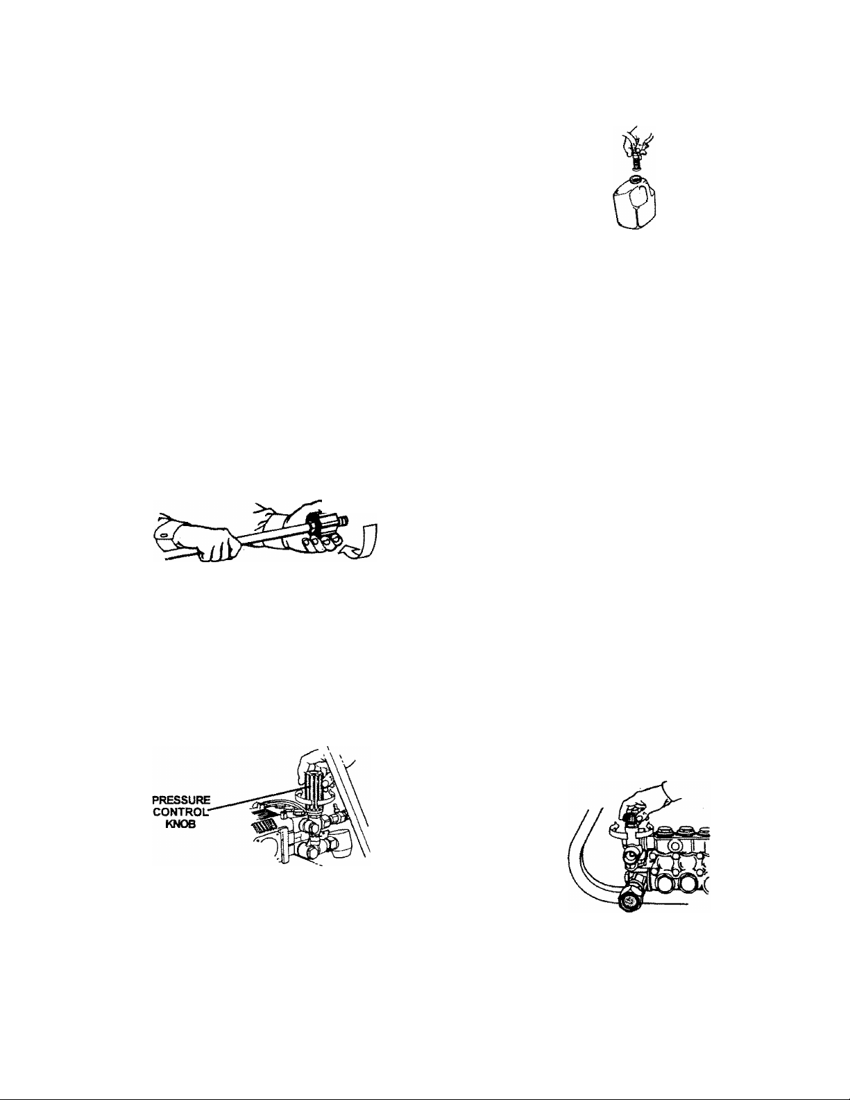
insert soap/chemical tine into your container
(soap/chemicals not included).
A Warning: Never adjust spray pattern when spray
ing. Never put hands in front of spray nozzle to
adjust spray pattern because you could be injured.
How To Use Your Pressure Washer
On the end of your spray gun is a nozzle that you can
twist from side to side. With the adjustable nozzle you
can adjust the nozzln.to either high pressure or low
pressure.
• Turn the nozzle in a counter clockwise direction to
achieve low pressure. Turn nozzle clockwise for high
pressure.
• For most effective cleaning, keep spray nozzle
between 8 and 24 inches of cleaning surface.
IMPORTANT; If you get spray nozzle too close,
especially on high pressure, you may damage the
cleaning surface.
• The pressure control knob Is located on the pump.
You can increase the pressure by turning the knob
clockwise or decrease the pressure by turning the
knob counterclockwise.
NOTE: The first step involves applying an appropriate
soap/chemical solution to penetrate and loosen grime.
The soap/chemical applied at low pressure to avoid
splashing, over spray and waste. Leave the solution
on surface for 3 to 5 minutes to allow solution to work.
NOTE: The second step involves cleaning the surface
you have prepared with the pressure washer and then
rinsing it clean.
• Turn the adjustable nozzle counter clockwise to low
pressure mode. Soap/chemicals cannot be applied
with nozzle in high pressure position.
• Review the use of the adjustable nozzle.
• Connect garden hose to water inlet (see ’To Start Your
Pressure Washer”), check that high pressure hose is
connected to spray gun and pump (see Assembly),
and start engine.
• Apply soap/chemicals to dry surface, starting
bottom and working up.
• Allow the soap/chemicals to soak in between 3-5
minutes before washing and rinsing.
• For cleaning, start at lower portion of area to be
washed and work upward, using long, even over
lapping strokes.
Your pressure washer is equipped with a chemical
injector adjustment knob. With the knob fully opened
you will get a 7 to 1 water to chemical ratio. With knob
fully closed you will get no chemical draw. Turn knob in
counterclockwise direction to achieve more chemical
draw and clockwise for less chemical draw.
NOTE: The maximum pressure for the unit is factory
adjusted. Do not attempt to adjust beyond this factory
setting.
Using Soaps/Chemicals
IMPORTANT: Use soaps and chemicals that are
designed specifically for use with pressure washers, to
apply soap/chemicals follow these steps:
• Prepare the soap/chemical as required by your job.
•
After using the pressure washer, it is recommended
the pump, chemical injector and chemical line be
flushed with clear water. To do so, simply place
chemical injector hose in water and siphon for 1 tflH
minutes.
Page 9

stopping Your Pressure Washer
Engine Oil
A CAUTION: Do not run pump without the water
supply connected and turned on. Failure to do so
will result in pump damage.
* To turn pressure washer off place the on/off switch
to the OFF position.
• Simply shutting OFF engine will not release pressure
in the system. Squeeze the trigger on the spray gun
for about 3 seconds to relieve pressure. Spray
stream wilt decrease in length.
IMPORTANT: This unit is equipped with a thermal relief
valve. If unit is allowed tp run for several minutes
without pressing the trigger on the spray gun, several
drops of water may be released through this valve to
cool the unit. The heated water will be purged from the
bottom of the pump.
Your unit has been shipped without oil in the engine.
A bottle of SAE 30 weight oil is included in the
carton. Remove oil dip stick located on the side of
engine. The oil dip stick is clearly marked with a
lines that tells you when unit has enough oil. Do not
fill above this point. Pour slowly.
NOTE: When adding oil to the engine crankcase, use
a high quality detergent oil classified “For Service SF,
SG, SH rated SAE 30 weight Use no special addi
tives. Select the oil’s viscosity grade according to
your expected operating temperatures.
SAE Vise party Gmäe«
101K-3Ü
BEFORE STARTING THE ENGINE
To operate the engine you will need to do the following.
A CAUTION: Always check engine oil level before
every start. Running engine low of oil or out of oil
could result in serious damage.
A CAUTION: Always check pump oil level before
every start. Running pump low on oil could result
in pump damage.
Adding Pump Oil
Before running the high pressure washer, check the
pump oil level by viewing the sight glass on the side of
the pump. When properly filled, the oil will be at the
half way point marked by the two triangles. Your
pressure washer pump is shipped with oil. Add oil only
if oil level is lower than the half way point on the sight
glass. Do not overfill. Use 30 weight non-detergent oil
If necessary.
A CAUTION: Do Not use engine oil that has been
shipped with your unit in your pump. Engine oil is
detergent and your pump uses a non-detergent oil
Detergent oil can cause damage to your pump.
ftTAHUMG TCMPSaATURE WnCtWTED SEFORC NEXT OtL CHWtQE
Air cooled engines run hotter than automotive engines.
The use of multi-viscosity oil such as {10W-30, etc.) in
ambient temperatures above 40“F (4*C) wilt result in
higher than normal oil consumption. If multi-viscosity
oil is used, check the oil level more frequently to
prevent any posssible engine damage due to lack of
lubrication.Use of SAE30 oil below 40“F (4*C) wilt result
in hard starting and possible engine damage due to
inadequate lubrication.
Gasoline
Your pressure washer engine is 4 cycle. Use unleaded
fuel only.
A CAUTION: Do not overfill the fuel tank. Always
allow room for fuel expansion.
A WARNING: Never fill fuel tank indoors. Never
fill fuel tank when engine Is running or hot. Do
not smoke or have open flame when filling fuel
tank.
Use clean, fresh, regular unleaded gasoline with a
minimum of 85 octane. Do not mix oil with gasoline.
If unleaded fuel is not available, leaded fuel may be
used-
Page 10

IMPORTANT: it is important to prevent gum deposits
from forming in essential fuel system parts such as the
carburetor, fuel filter hose or tank during storage. Also,
experience indicates that alcohol-blended fuels (called
gasoho! or using ethanol or methanol) can attract mois
ture which leads to separation and formation of acids
during storage. Acidic gas can damage the fuel system
of an engine while in storage. To avoid engine problems,
the fuel system should be emptied before storage of 30
days or longer. Never use engine or carburetor cleaner
products in the fuel tank or permanent damage may
occur.
NOTE: Never start pressure washer without water
source turned on and connected to pressure washer.
To Start Your Pressure Washer
Make sure fuel shutoff valve is turned to the open
position.
CLOSED
OPENED
Squeeze trigger on pressure washer wand to relieve air
pressure caused by turning on the water. Water will
spew out of the gun in a thin stream. This will make it
easier to start the engine.
Engage the safety latch on the spray gun. This locks
the trigger in place and keeps you from accidentally
spraying a high pressure stream.
On the engine there is a choke/run lever. Place lever
to the choke position.
CHOKE
LEVER
• Remove gas cap
• Add unleaded gasoline, slowly, to fuel tank.
• Do not overfill.
Connect garden hose to the water inlet on the
pressure washer. Tighten by turning water inlet
counterclockwise.
Connect high pressure hose to discharge on pump.
Connect the garden hose to the water spout
and turn water supply on.
On the engine there is a throttle control lever. Place
throttle to the rabbit position. Always start engine
with throttle in the rabbit position. Place on/stop
switch to the “on" postion.
Grasp the starter grip and pull slowly until resistance
is felt, then pull firmly to start engine.
When engine starts, gradually move choke lever to
RUN position.
If engine does not start after 5 pulls, place choke
back to run position.
For hot engine starts make sure choke lever is in
the run position. Make sure fuel shut off valve is open
and throttle is in the rabbit position.
NOTE: If any leaks are present shut unit down and
tighten fittings.
10
Page 11

MAINTENANCE
OSTOMER RESPONSIBILITIES TABLE
m
MAINTENANCE TASK
PRESSURE WASHER
Check/clean mlet screen.
Check high pressure hose.
Check soap and chemical hose and filter X
Check gun and vv^nd for leaks.
Purge pump ofairand contaminants
Check pump oil
Change pump oil
ENGINE
Check oil level
Change engine oil X
Before each use
X
X
X
X
X
X
Every 25
hours or yearly
---------------
tvery 50
hours oryearty
X
Every 100
hours oryearly
roduct Specifications
é
Pressure Washer Specihcations
Pressure 2700
Flow Rate
Cleaning Units {psi x GPM)
Engine Specifications
RPM
Rated Horsepower
Spark Plug
Gasoline Capacity 4.6 Quarts
Oil SAE 30 weight
0.030” (0.76mm)
3.0 GPM
8100
3600
7.5
General Recommendations
The warranty of the high pressure washer does not
cover items that have been subjected to operator
abuse or negligence. To receive full value from the
warranty, operator must maintain high pressure
washer as instructed in this manual.
Some adjustments will need to be made periodocally to maintain your high pressure washer.
All adjustments in the Maintenance section of this
manual should be make at least once each season.
Once a year you should clean or replace the spark
plug and clean or replace the air filter and check
the gun and wand assembly for wear. A clean
spark plug and clean air filter assure proper
fuel-air mixture and help your engine run better
and last longer.
NOTE: Over time the o-rings in the gun assembly
become worn. Attached to your owners manual is a
replacememt o-ring and split backup ring.
11
Page 12

Pressure Washer Maintenance
Check and Clean Inlet Screen: Examine inlet screen
on pump inlet fitting. Clean if clogged replace if torn.
Check High Pressure Hose: High pressure hose can
develop leaks from \wear, kinking, abuse, inspect hose
each time before use. Check for cuts, leaks, abrasions
or bulging of cover, damage or movement of couplings.
If any of these conditions exist, replace hose
immediately.
Check Chemical/Soap Hose: Examine the chemical/
soap hose and clean if clogged. Hose should fit tightly
on pump fitting. Check for leaks and tears. Replace
filter or hose if either is damaged.
Check Gun and Wand: Examine hose connection to
gun making sure it is secure. Test trigger by pressing it
and making sure it springs back into place when you
release it.
Pump Oil
Pump oil level should be checked before each use.
Changing Pump OH
Oil should be changed after the first 10 hours of opera
tion. Subsequent changes after each 50 hours of opera
tion. To drain oil, simply remove oil plug with a adjust
able wrench. The oil plug is located at the bottom of the
pump. Dispose of used oil. Properly remove pump oil fill
plug. Add 30 weight non-detergent oil. Fill until oil level is
tat the mid point on the sight glass.
Pull the trigger on the gun and hold.
When the water supply is steady and constant,
disengage trigger and refasten the wand extension.
Engine Maintenance
Oil
• Oil level should be checked prior to each use
or at least every 5 hours of operation. To check oil see
Adding Engine Oil on page 9.
Changing Engine Off
For a new engine, change oil after the first 5 hours of
operation. Thereafter, change oil after every 50 hours of
operation.
Change the oil while the engine is still warm. The oil will
flow freely and carry away more impurities. Make sure
the engine is level when filling, checking, or changing oil.
Change the oil as follows:
• To keep dirt, grass clippings, etc., out of the engine,
clean the area around the drain plug and dipstick
before removing it.
• Remove the oil drain plug and dipstick. Tilt the engine
slightly towards the oil drain to obtain better drainag^
Be sure to allow ample time for complete drainage. "
Purge Pump of Air and Contaminants
To remove the air from the pump, follow these steps;
• Set up the pressure washer as described in
Assemb/y section and connect the water supply.
• Remove the wand extension from the spray gun,
• Pull the trigger on the gun and hold.
To remove the contaminants from the pump, follow
these steps;
• Set up the pressure washer as described in
ASSEMBLY section, connect the water supply.
• Remove the wand extension from the spray gun.
• Start the engine according to instructions in the
OPERATION section.
• Reinstall the drain plug. Make sure it is tightened
securely.
• Fill the crankcase with new oil of the proper type, to
the Full mark on the dipstick. Always check the level
with the dipstick before adding more oil.
12
Page 13

Reinstall the oil fill cap or plug and tighten securely.
Service Air Cleaner
NOTE; Do not use petroleum solvents, e.g., kerosene,
which will cause the cartridge to deteriorate. Do not use
pressurized air to clean cartridge. Pressurized air can
damage the cartridge.
To service air cleaner follow these steps:
1. Unscrew cover screws. Remove cover and air cleaner
assembly.
2. Remove cartridge from cover, then retainer
(if equipped) and pre-cliianer.
To service pre-cleaner, wash in liquid detergent and
water. Squeeze dry in a clean cloth. Saturate in engine
oil. Squeeze in clean, absorbent cloth to remove all
excess oil. Replace if very dirty or damaged.
To service cartridge, clean by tapping gently on a flat
surface. Do not oil cartridge. Replace if dirty or dam
aged.
TE: Do not use petroleum solvents, e.g., kerosene,
hich will cause the cartridge to deteriorate. Do not use
^^hi
pressurized a/rto clean cartridge. Pressurized air can
damage the cartiridge.
3. Reassemble pre-cleaner or retainer (if equipped.)
Place in cover with pre-cleaner mesh side toward
cartridge. Place cartridge in retainer in cover.
4. Push cover and air cleaner assembly squarely onto
base (tabs must be in slots, if equipped) and hold
firmly. Tighten cover screws securely.
Do not clean engine with a forceful spray of water
because water could contaminate fuel system. With
a brush or doth clean finger guard after every use to
prevent engine damage caused by overheating.
Before running engine, clean muffler area to remove all
combustible debris.
Clean and Replace Spark Plug
Change the spark plug every 100 hours of operation or
once each year, whichever comes first. This will help
your engine to start easier and run better.
Keep engine and parts clean!
13
Page 14

SERVICE AND ADJUSTMENTS
Carburetor
The carburetor of your high pressure washer is pre-set
at the factory. The carburetor should not be tampered
with, if your pressure washer is used at an altitude in
excess of 5000 feet consult with your nearest Sears
Service Center regarding high altitude set changes.
A CAUTION; Engine speed was properly adjusted
at the factory and should require no additional
adjustment. Do not attempt to change engine
speed. If you believe the engine is running too fast
or too slow, take your pressure washer to a Sears
Authorized Service Center for repair and adjustment.
A WARNING; High engine speeds are dangerous and
increase the risk of personal injury or damage to
equipment.
A CAUTION: Low engine speeds impose a heavy
load on the engine and when sufficient engine power
is not available could shorten engine life.
Nozzle Maintenance
Hi-Low Lance:
1.
Shut off the pressure washer and turn off the water
supply.
2.
Disconnect spark plug wire.
Pull trigger on gun handle to relieve any water
3-
pressure.
4.
Disconnect the wand/lance from the gun.
Rerhove the high-pressure nozzle from the lance.
5.
Remove any obstructions with the nozzle cleaning
tool provided and backflush with clean water.
6.
Direct water supply into nozzle end to backflush
loosened particles for 30 seconds.
Reassemble the nozzle to the iance using teflon tape
to prevent teaks. Tighten securely.
8.
Reconnect wand/lance to gun and turn on water
supply.
9.
Start pressure washer and place wand/lance into
high pressure setting to test.
STORAGE
This pressure washer should be stored in such a way to
protect it from freezing. Do not store this unit outdoors
or in an area where temperatures will fall below 32° F.
This can cause extensive damage to this unit.
If unit has to be stored under freezing conditions a non
toxic R.V. anti-freeze can be used to protect from
freezing.
Preparing Pressure Washer for Storage
NOTE: If you do not plan to use your unit for 30 days or
more, unit should be prepared for storage.
Engine Preparation
• First add a fuel stabilizer to the fuel tank.
• Run pressure washer for full 5 minutes to allow fuel
stabilizer to enter the fuel system.
NOTE: While doing this procedure make sure water
supply is turned on and flowing to the unit. NEVER run
unit without water supply running through pump.
• Next shut off engine and disconnect the water supply.
• Disconnect the spark plug wire and remove the spark
plug.
• Add one teaspoon of oil through the spark plug hole.
• Place rag over spark plug hole and pull the recoil a
few times to lubricate the combustion chamber.
• Replace the spark plug, but do not connect the spark
plug wire.
Pump Preparation
• Be sure engine switch is in “OFF” position and spark
plug wire has been removed from spark plug.
• Pull the trigger on the spay gun to release the
pressure in the high pressure hose. Detach high
pressure hose and garden hose from the unit.
• Pul! the recoil on the engine 4 to 6 times to discharge
remaining water in pump.
• Tip the unit on the end with the water inlet fitting
pointing upward.
• Pour approximately 1/4 cup of non-toxic R.V. anti
freeze down the fitting where the water hose attaches
to the pump.
• Set unit upright and pull starter handle on engine 4 to
6 times to circulate anti-freeze in pump until anti
freeze is discharged from the pump.
14
Page 15

TROUBLESHOOTING
i SYMPTOM
Engine won’t
start
Won’t Draw
Chemical
Pump running
normally but
pressure does
not achieve
rated values
CAUSE
1. Engine throttle is in "OFF" Position.
2. Choke lever has not been placed to
choke.
3. Pressure buildup after initial use.
1. Nozzle not in chemical draw position.
2. Chemical screen is obstructed.
3. Chemical screen not working.
4. Chemical injector orifice obstructed
or stuck.
5. Chemical injector closed.
1. Water supply resfiicted.
A
2. Nozzle is in low PSI position.
3. Nozzle incorrect or worn.
4. Pump sucking air.
5. Nozzle blocked.
SOLUTION
1. Slide throttle to "Rabbit" position.
2. Slide choke lever to choke position.
3. Depress trigger gun.
1. Place nozzle to low pressure.
2. Check chemical screen; clean if obstructed.
3. Make sure chemical screen is submerged in
chemical/water.
4. Check and clean.
5. Open chemical injector by turning adjustment
knob.
1. Check water supply and filter screen for.
blockage. Check hoses for blockage, kinks,
teaks, etc.
2. Pull nozzle at end of wand back to the high pressure
position.
3. Check and replace.
4. Check that hoses and fittings are air-tight.
5. Clean nozzle-
Fluctuating
1 Pressure
Pressure drops
after period of
normal use
Pump noisy 1. Water too hot.
Presence of
water in oil (oil
milky).
Water dripping
from pump
|i
Oil Dripping
1. Pump sucking air.
2. Garden hose inlet strainer clogged,
3. Worn Seals or Packing.
4. Inadequate water supply.
5. Fouled or dirty inlet or discharge
valves.
6. Leaky discharge hose.
1. Nozzle clogged, partially obstructed.
2. Nozzle worn.
3. Pump Valves worn, dirty or stuck.
4. Worn pump piston packing.
2. Pump sucking air.
3. Valves dirty or worn.
4. Worn bearings.
1. High humidity.
2. Piston packing and oil seal worn.
1. Thermal relief functioning normal.
2. Fittings Loose.
3. 0-rings of piston guide or retainer
worn.
4. Piston packing worn.
1. Oil sea! worn
2. Loose drain plug or worn drain plug
o-rinq.
1. Check that hoses and fittings are air tight. Purge air
from garden hose.
2. Clean. Check filter frequently.
3- Check and replace.
4. Check hose for kinks.
5. Check flow available to pump. Check for
excessive heat, 145^ F or above.
6. Clean inlet and discharge valve assemblies.
Replace if damaged.
1. Use nozzle cleaning kit to clear obstruction. (See
Nozzle Maintenance under Service Adjustment.)
2. Clean or replace.
3. Check and replace.
4. Check and replace.
1. Reduce temperature below 63° C or 145° F.
2. Check that hoses and fittings sure air tight.
3. Check, clean or replace.
4. Check and replace if necessary.
1. Change Oil.
2. Check and replace oil seals.
1. Protecting pump, if not using pressure washer for
a long period of time, shutoff engine.
2. Tighten.
3. Check and replace.
4. Check and replace.
1. Check and replace
2. Tighten drain plug or replace 0-ring. Do not overtorque.
15
Page 16

PARTS
CRAFTSMAN 2700 PSI HIGH PRESSURE WASHER 919.762700
3,
KEY#
1
2
3
4
5
6
7
8
9
10
11 15111
12
13
14
15
16
17
18
19
20
16532
16470
16396
16535
16371
16471
16503
P657
H100
15043
16529
T527-04
16727
PK16803
F035
P655
F464
F064
DESCRFnON
Handie
JBoli
Gun
TtrePnu^atic
Foot Rubber
Knob
Frame
0-ring Kit
Chemical Hose and Filter
Lance Hi/Low
High Pressure Hose
Decal Front Craftsman
Axle
Engine
Decal Operation
Pump
High Pressure Quick Connect
Adapter- Garden Hose
Nut Pal 5.8"
Screw Hex HDC
PARTS NOT ILLUSTRATED
MGP-762700
F078
F119
F066
FI 07
16106
F074 Flat Washer - Pump to Engine
NCT001
16776 Easy Start Valve
Owners Manual
Lockwasher. Engine to Frame
Nut Hex 5/16"- Engine to Frame
Screw 5/16"- Engine to Frame
Lockwasher- Pump to Engine
Srew, Hex- Pump to Engine
Nozzle Cleaning Tool
16
Page 17

PUMP PARTS
CRAFTSMAN 2700 PSi HIGH PRESSURE WASHER
919.762700PUMP NUMBER PK16803
17
Page 18

PUMP PARTS
CRAFTSMAN 2700 PSI HIGH PRESSURE WASHER 919.762700 PUMP NUMBER PK16803
RS=.
NO.
1
2
3
4
5
6
7
8
9
10
11 AR-1260790
12
13
14 AR-880130 Oil cap
15 AR-1780050
16 AR-1780510
17
18
19
20
21
22 AR-1260091
PART
NO. DESCRiPnON
AR-960160
AR-1260162
AR-1269050 Complete valve
AR-880830
AR-620301
AR-1780130
AR-1260130
AR-1780090
AR-1780010 Pump body
AR-1266740 Cap
AR-1780550 Snap ring
AR-1780490
AR-1200430
AR-1789010 Complete cover
AR-1780040 Con rod
AR-1780060
AR-480480
0-Ring
Plug
0-Ring 6
Plug
Support ring 3
Gasket
Piston guide
Circlip
Bearing
Piston pin 3
O-Ring
Screw 6
Guiding piston 3
O-Ring 3
Spacer disc
OTY.
6
6
6
1
3
3
1
1
1
1
1
1
1
1
3
3
PART
NO.
23
24
25
27
28 AR-880530 Plug
30 AR-1260460 Seal
31
32 AR-770260 O-Ring
33 AR-1260440 Gasket
36
37
38 AR-680570
40
41
42 AR-480671
44 AR-180030
60
61
62
67 AR-820440 Grub screw
68
69
70
71
NO.
AR-1780070 Piston
AR-1260100 Piston washer
AR-1260110
AR-740290
AR-1780100 Rear piston guide
AR-1780380 Head
AR-1381550 Washer
AR-1321160
AR-1321080 Snap ring
AR-1780340 Hollow shaft 0 1
AR-1380550
AR-1780430
AR-1789200 Pump head pre-ass 1
16802
16749
16506
DESCRIPTION
Nut
O-Ring
Screw
Bearing
Seal
Screw
Gas engine flange
13ushing 1
Chemical Injector
Unloader
Thermal Relief Valve
OTY.
3
3
3
2
2
3
3
3
3
1
8
8
1
1
1
4
1
1
1
1
1
3
A*Knr 16739
Valves
Pos. Qty.
3 é
4 6
D«KIT 16745
Water Seals
Pos. Qty,
7 3
32 3
33 3
PARTS KITS
B*KIT 16746
Pistor^
Pos. Qty.
23 3
F=KIT 16749 L^KIT 16750
Bearings
Pos. Qty. Pos. Qty.
13 1 70 1
40 1
C«K!T16748
Oil Seals for
D Version
Pos. Qty,
10 1
16 1
30 3
42 1
Unloader
18
K*KIT 16802
Pos. Qty.
69 1
Page 19

ENGINE PARTS
CRAFTSMAN 2700 PSI HIGH PRESSURE WASHER 919.762700 ENGINE NUMBER 138432-0035~A1
373©
227
10%
REF. PART
NO. NO.
1 715461
3 «710000
306
REF.
DESCRIPTION
Cylinder Assembly 10
Seal-Oil
NO.
15
17
116
116A • 710091
227
230
277
306
356
PART
NO.
710023
715000 Plug-Oil Drain
710003
•710055
710051
•710058
710004
710063
710308 Wire-Oil Sensor
DESCRIPTION
Screw-Hex
Bearing-Ball
Seai-O-Ring 616
Seal-O-Ring
Lever-Governor 725
Washer-Spacer 890
Washer-Seal
Sheild-Cylinder
REF.
NO.
373
506
614
718
1019
1062
1058
PART
NO.
710059
710090
710056
710636
710005
710102
715136
715031
715353 Sensor-Oil
273126
DESCRIPTION
Nut-Lock
Nut-Lode
Pin-Retainer
Crank-Governor
Pin-Locating
Sheild-Heat
Bracket-Support
Label Kit
Owner's Manual
«Included in Gasket Set-Part No. 715482
★ included inValve Oveitiaut Kit-Part No. 715483
Alnciuded in Carburetor Kit-Part No. 715484
★ Included in Gasket Gasket Set -Part No. 715485
19
Page 20

ENGINE PARTS
CRAFTSMAN 2700 PSI HIGH PRESSURE WASHER 919.762700
22
22A
523
116B
ENGINE NUMBER 138432-0035-AT
219
REF.
NO.
12 • 710628
17 710003
18 715463 Cover-Crankcase
2022• 710216
«Included in Gasket Set-Part No. 715482
★ Included inValve Overhaul Kit-Part No. 715483
Aincluded in Carburetor Kit-Part No. 716484
-f Included in Gasket Gasket Set -Part No. 715485
PART
NO,
710032
DESCRIPTION
Gasket-Crankcase
Bearing-Ball
Seal-Oil
Sorew-Hex.
REF.
NO.
22A 710306
116B •710029
219
220 710035
PART
NO.
715341
DESCRIPTION
Screw-Hex
Sea!-0~Ring
Gear-Governor
Washer-Spacer
20
REF.
NO.
221
225 710028
523 715007 Dipstick
718 710005
PART
NO-
710027
DESCRIPTION
Cup-Govemor
Shaft-Governor Gear
Pin-Locating
Page 21

ENGINE PARTS
CRAFTSMAN 2700 PSI HIGH PRESSURE WASHER 919.762700
ENGINE NUMBER 138432-0035-A1
REF.
NO.
40A
[Included in Gasket Set-Part No. 715482
Fincluded inValve Overhaul Kit-Part No. 715483
Ainciuded in Carburetor Kit-Part No. 715484
Alnctuded in Gasket Gasket Set -Part No. 715485
PART
NO.
715444
5
7 »*710624
10
710023
13
710020 Screw-Hex
33
715445
34
715446
710011
35
40
710012
715130
DESCRIPTION
Head-Cylinder
Gasket-Cylinder Head
Screw-Hex
Valve-Exhaust
Valve-intake
Spring-Valve
Retainer-Valve
Retainer-Valve Plug 1050
ref
NO.
53A
373A 710007
PART
NO.
45 710008
53 710148
710099
337 491055
383 19374
551
715450
DESCRIPTION
Tappet-Valve 635
Stud-Carburetor 830
Mounting 868
Stud
{Muffler Mounting)
Plug-Spark 1026
Nut-Lock
Wrench-Spark 1034
Cover-Rocker
21
REF.
NO.
1022 »*710626
1029
PART
NO.
710634 Boot-Spark Plug
710016
»710019 Seal-Valve
710622 Rod-Push
710014 Arm-Rocker
710017 Guide-Push Rod
710015 Adjuster-Rocker Arm
DESCRIPTION
Stud-RodterArm
Gasket-Rocker
Cover
Page 22

ENGINE PARTS
CRAFTSMAN 2700 PSI HIGH PRESSURE WASHER 919.762700
ENGINE NUMBER 138432>0035>A1
REF. PART REF.
NO,
16 715426 Crankshaft 25
#!nduded in Gasket Set-Part No. 715482
★ Included inValve Overiiau! Kit-Part No. 715483
Ainciuded in Carburetor Kit-Part No. 715484
★ Included in Gasket Gasket Set -Part No. 715485
NO.
DESCRIPTION
Used on Type No{s).
0035, 0084
NO. NO.
26
PART
DESCRIPTION NO.
715456 Piston Assy. 27
(Standard)
715457
715448 Piston Assy.
715452
715453
715454
Piston Assy.
(.010” O.S.)
(.020" O.S.) (.020” Undersize)
Ring Set
(Standard) Rod
Ring Set
(.010" O.S.)
Ring Set
(.010” O.S.)
22
REF.
28
29 715427 Rod-Connecting
32
46
718A
1051
PART
NO. DESCRIPTION
710040
715455
715502
710041
715451
710616
710039 Ring-Retaining
Lock-Piston Pin
Pin-Piston Std.
(Standard)
Rod-Connecting
Screw-Connecting
Grear-Cam
Pin-Compression
Page 23

ENGINE PARTS
CRAFTSMAN 2700 PSI HIGH PRESSURE WASHER 919.762700
ENGINE NUMBER 138432-0035-A1
163 Co
ref
NO.
51 •*a+710060
95
98
104
105
108
117
•
•
•
PART
NO.
710672
715478
710663
710661
710674
710665
710719
122
125
715034
715473
DESCRIPTION
Gasket-Intake
Screw-Round Head
Screw-Idle Speed
Pin-Float
Valve-Needle
Valve-Choke
Jet-Main
-NOTEJet-Main
{High Attitude)
Spacer-Carburetor
Carburetor
ref
NO.
130
PART
NO,
710671 Valve-Throttle 634A
131 715480
133
715477 Float-Carburetor 634B
137
138
141
142
147
715479
• 710664
• 710676
710720 Jet-Pilot
154 710081
163 t*A+710639
620
710635
1S4
1043
PART
NO.
•
•
DESCRIPTION
Seal-Throttle Shaft
(Sold in Kit Only)
Bushing-Choke
Shaft
DESCRIPTION
Shaft-Throttle
Gasket-Float Bowl
REF.
NO.
(Sold in Kit Only) (Sold in Kit Only)
Washer
(Sold in Kit Only)
Choke Shaft Kit 955A
Nozzle-Carburetor 975
955
710667
710679
715476
Screw-Bowl
Mounting
Plug-Carburetor
Bowl-Float
Jet-Pilot
-riuic-
(High Altitude)
Nut-Hex
Gasket-Air Cleaner
Bracket-Control
•Included in Gasket Set-Part No. 715482
★ Included inValve Overhaul Kit-Part No. 715483
Ainctuded in Carburetor Kit-Part No. 715484
★ Included in Gasket Gasket Set -Part No. 715485
23
Page 24

ENGINE PARTS
CRAFTSMAN 2700 PSl HIGH PRESSURE WASHER 919.762700
sa\
51^
S35
ENGINE NUMBER 138432-0035-
663^
467
REF.
NO.
11
51 ***+710060
53
129
161
•Included in Gasket Set-Part No. 715482
★ Included inValve Overtiau! Kit-Part No. 715483
Alncluded in Carburetor Kit-Part No. 715484
★ Included in Gasket Gasket Set -Part No. 715485
PART
NO.
710115
710148 Stud-Carburetor
715024
710521
DESCRIPTION
Tube-Breather
Gasket-Intake
Mounting
Screw-Governor
Speed
(High and Idle
Speed Adjustment)
Base-Air Cleaner
REF. .
NO.
202
209
232
235
354
467
535
PART
NO. DESCRIPTION
710637 Link-Mechanical
Governor
710702 Spring-Governor
710638 Spring-Link
710522
710068
280715 Knob-Control
491435
Shieid-Fue! Spray
Nut-Hex
Filter-Air
24
REF.
NO.
6208
663
967
968
969
PART
NO. DESCRIPTION
715025 Bracket-Control
710057
491588 Air Filter
495872
93473
Screw-Hex
Cover-Air Cleaner
Sorew-Hex
Page 25

ENGINE PARTS
CRAFTSMAN 2700 PSI HIGH PRESSURE WASHER 919.762700
ENGINE NUMBER 138432-0035>A1
505
53A
REF. PART
NO. NO. DESCRIPTION
53A 710099 Stud
{Muffler Mounting)
300 715508 Muffler-Exhaust
408 710307 Screw-Phillips
505 710090 Nut-Lock
•Included in Gasket Set-Part No. 715482
^Included InVaive Overhaul Kit-Part No. 715483
Aincluded in Carburetor Klt-Part No. 715464
<*>lnciuded in Gasket Gasket Set -Part No. 715485
REF. PART
NO. NO. DESCRIPTION
663 710057 Screw-Hex
673 93705 Screw-Hex
676 715230 Deflector-Muffler
737 710074 Screw-Hex
823 710248 Screw-Hex
REF. PART
NO. NO. DESCRIPTION
832 710565 Guard-Muffler
863 714319 Bracket-Muffler
883 #*710082 Gasket-Muffler
994 715491 Arrester-Spark
1075 710329 Screen-Outlet
25
Page 26

ENGINE PARTS
CRAFTSMAN 2700 PSI HIGH PRESSURE WASHER 919.762700
ENGINE NUMBER 138432-0035-A1
663A
240A
18?!^
REF.
NO.
187A 715126 Line-Fuel
PART
NO.
10
710023
180 715431
181
710490
187
715125
DESCRiPTION
SoBw-Hex
Tank-Fuel
Cap-Fuel Tank
Line-Fuel (8mm ID)
(Fuel Tank-To-Filter/
Shut-off)
(Cut to Required
Length)
(4mm ID)
(Fiiier/Shut-Off-ToCarburetor)
(Cut to Required
Length)
187A|
REF.
NO.
187B
240A
601A
PART
NO. DESCRIPTION
296004
710065
210
715027
240
298090 Filter-Fuel
710071 Fitter-Fuel
243
710070 Bowl-Filter
246
710068 Nut-Hex
354
• 710072 Seal-O-Ring
524
601 710067
710075
601A
Line-Fuel
{0.25" ID)
(Carburetof-T e-Filter)
(Cut to Required
Length)
Strainer-Fuel
Fitter-Fuel
Clamp-Hose
Clamp-Hose
18781
REF.
NO.
6018
617
663A
666
670
601B
PART
NO.
93053
•710069 Seal-O-Ring
710160
710066
710159
DESCRIPTION
Clamp-Hose
Stxew-Hex
Gauge-Fuel
Spacer-Fuel Tank
♦included in Gasket Set-Part No. 715482
^Included inValve Overtiaui Kit-Part No. 715483
Alnciuded in Carburetor Kit-Part No. 715484
+!ncluded in Gasket Gasket Set -Part No. 715485
26
Page 27

ENGINE PARTS
CRAFTSMAN 2700 PSI HIGH PRESSURE WASHER 919.762700
ENGINE NUMBER 138432-0035-A1
REF.
NO.
281
•Included tn Gasket Set-Part No. 715482
^Included inValve Overhaul Klt-Part No. 715483
Ainciuded in Carburetor Kit-Part No. 715484
^Included in Gasket Gasket Set -Part No. 715485
PART
NO. DESCRIPTION
10
710023
710646
Screw-Hex
Panel-Control
Used on Type No{s).
0035
REF.
NO.
304
305
347
PART
NO.
715465
710095
493521
REF.
DESCRIPTION
Housing-Blower 356A
Screw-Hex
Switch-Rocker
(Without Lamp) 6638 710234
27
NO.
3568
663A
670 710159
813 710083
1036 499350
1053 710305
PART
NO.
710120
710087
710160
DESCRIPTION
Wre-Stop
Wre-Stop
Screw-Hex
Screw-Hex
Spacer-Fuel Tank
Clamp
Labe! Kit-Emission
Module
Page 28

ENGINE PARTS
CRAFTSMAN 2700 PSI HIGH PRESSURE WASHER 919.762700
1054
332A
455
334*^^
ENGINE NUMBER 138432-0035
m
737 Ç
737
890A
332
ref
NO.
281A
332A 710345
•included in Gasket Set-Part No. 715482
★ Included inValve Overhaul Kit-Part No. 715483
★ .Included in Carburetor Kit-Part No. 715484
★ Included in Gasket Gasket Set -Part No. 715485
part
NO. DESCRIPTION
715429
23
120
154
332 710048
333
93836 Washer-Lock
93837
710658 Panel-Control
715464
Flywheel
Nut-Hex
Nut-Hex
Nut-Hex
Armature-Magneto
REFNO.
334
354
356C
455
475
521
526
729
737
PART
NO. DESCRIPTION
710047
710068
710324
710277
715200
710045
710089
710046
710074
Saew-Hex
Nut-Hex
Wire-Ground
Cup-Flywheel
Rectifier
Shielding-Cable
Srew-Hex
Clip-Wire
Screw-Hex
REF.
NO.
890A
892
990
1054
PART
NO.
710644
493625
392832
710349
DESCRIPTION
Bracket-Support
Key Switch
(includes Keys)
Key Set-Starter
Switch
Tie-Cable
28
Page 29

ENGINE PARTS
CRAFTSMAN 2700 PSI HIGH PRESSURE WASHER 919.762700
737
ENGINE NUMBER 138432-0035-A1
REF.
NO.
55
56 710274
57
#lnciuded in Gasket Set-Part No. 715482
PART
NO. DESCRIPTION
715132 Housing-Rewind
Starter
Pulley-Starter
710270 Spring-Rewind
Starter
REF.
NO.
58 710275
60 490652
456 710272
459 715256 Pawl-Ratchet
★ included inValve Overhaul Kit-Part No, 715483
Alncluded in Carburetor Kit-Part No, 715484
★ included in Gasket Gasket Set -Part No. 715485
PART
NO.
REF.
DESCRIPTION
Rope-Starter 461 805956 Screw-Shoulder
(Cut to Required
Length) 608 715133 Starter-Revwnd
Grip-Starter Rope 615 805952
Plate-Pawl Friction 737 710074 Screw-Hex
29
NO.
516 806953 Spring-Pawl
PART
NO. DESCRIPTION
Ring-Rewind Starter
Page 30

ENGINE PARTS
CRAFTSMAN 2700 PSI HIGH PRESSURE WASHER 919.762700 ENGINE NUMBER 138432<0031
1033 VAtV£ OVERHAUL KTT
368^
121 CARBURETOR KTT
104.^ 1380 105$ 147f
117 %
163
634A® 6348» 142|
51 137 CD
358 GASKET SET
1168 0 524 O 3
277© “
i
1022
977 CARBURETOR GASKET SET
51 1380 163 137<^
REF.
NO.
104 A
105 A
116 • 710055 Seai-OI!
116A • 710091
116B • 710029
117 A
•Included In Gasket Set-Part No. 715482
★ Included inValve Overhaul Kit-Part No. 715483
Alncluded in Carburetor Kit-Part No. 715484
★ Included in Gasket Gasket Set -Part No. 715485
PART
NO.
710000 Seal-Oil
3 •
7 •* 710624 Gasket-Cylinder Head
12 • 710628
710215 Seal-Oi!
20 •
51«*a+710060 Gasket-Intake
710663 Pin-Float
710661
710665 Jet-Main
DESCRIPTION
Gasket-Crankcase
Valve-Needle
Seal-O-Ring
Seal-O-Ring
REF.
NO.
121
137
138
142
147 A 710675 Jet-Pilot 868 * 710019
163 6*A+710639
277 • 710004 Washer-Seal
358 715482
524 • 710072
PART
NO. DESCRIPTION
715484 Carburetor Kit 617 *710069 Seal-O-Ring
A +
A^ Washer 634B
A 710664
Gasket-Float 634A
Bowl (Sold In Kit Shaft (Sold in Kit
Only)
(Sold in Kit Only)
Nozzle-Carburetor Only)
Gasket-Air Cleaner
Gasket Set
Seal-O-Ring 1022 •*710262
30
REF.
NO.
883 •★ 710082
977
1033 715483
PART
NO.
•
•
715485 Gasket Set-
DESCRIPTION
Seal-Throttle
Only)
Bushing-Choke
Shaft (Sold in Kit
Seal-Valve
Gasket-Exhaust
Carburetor
Gasket-Rocker
Cover
l^-Valve Overhaul
Page 31

Bdggs & StrattiKi Corporation (B&S), the Caltfomia Air Resources Board (CARS)
ie interest of the environment, B&S eiigines that meet strict emisprequirements are l^)e!ed, "This engine ctmforms to 1595 -1998
ifomia emission regulations for ULGE engines and U.S. EPA
f
Ríase 1 regulations lor small non-road engines."
EMISSION CONTROL WARRANTY COVERAGE IS APPLICABLE
CARS, U.S, EPA and B&S are pleased to explain die Emission
Control System Warranty on your 1996 and later utility or lawi and
garden equipment (ULGE) engine. In California, new ULGE engines
produced on or after August 1,1995 must be designed, built and
equipped to meet the State’s stringent anti-smog standards^ Else
where in me United States, new non-road, spark-ignition en^nes
certified for model year 1997 and later, must meet simfl^ standards
set forth by the U.S. EPA. 8&S must i^rant the emisión císitroi
system on your engine for the periocte of time listed below, provided
ULGE engines are warranted relative to emission aintrol parts below. If any covered part on your engine is defective, the part will be
defects for a period of two years, sul:^‘ect to provisions set forth r^iaired or r^ac^ by B&S.
As the ULGE engine owner, you are responsible fwthe performance
of tile required maintenance listed in your Operator/Owner Manud.
B&S recommends that you retain ail your rece^ (rovenng mainte
nance on your ULGE engine, tuit B&S cannot deny warranty sdely
for the lack of r^ieipis or ior your failure to ensure the performance d
all scheduled maintenance.
As the ULGE engine owner, you should however be aware that 8&S
may deny you warranty coverage if your ULGE engine or a part has
failed due to abuse, neglect, improper maintenance or unapproved
modifications.
The following are specific provisions relative to your Emission Ccmtrol Defw:to Warranty Coverage. It is in addition to the B&S engine warranty
^Bn-regulated engines found in the C^rator/Owier Manual.
arranted Parts
Coverage under this warranty extends only to the parts listed
below (the emission control systems parts) to the extent these
parts were present on the engine purchased,
a. Fuel Metering System
• Cold start enrichment system (soft choke)
• Carburetor and Internal parte
• Fuel Pump
Air induction System
b.
• Air cleaner
• intake manifold
Ignition System
c.
• Spark plug(s)
• Magneto ignition system
Catalyst System
d.
• Catalytic converter
• Exhaust manifold
• Air injection system or pulse valve
Miscellaneous Items Used in Above Systems
e.
• Vacuum, temperature, position, time sensitive valves
• Connectors and assemblies
2.
Length of Coverage
B&S warrants to the initial owner and each subsequent purchaser
a tax
that the Warranted Parts shall be free from defects in materiais
workmanship which caused the failure erf the Warranted
rts for a period of two years from the date the engine is deliv*
?ed to a retail purchaser.
Emission Control System Warranty Statement (Owner*« Defect Warranty Rights and Obligations)
and switches
and the United State« Envtronmentat Protection Agency (U.S. EPA)
TO CERTIFIED ENGINES PURCHASED IN CALIFORNIA IN 1995
AND THEREAFTER, WHICH ARE USED IN CAUFORNIA. AND
TO CERTIFIED MODEL YEAR 1997 AND LATER ENGINES
WHICH ARE PURCHASED AND USED ELSEWHERE IN THE
UNITED STATES.
California and United States Bnlsslon Ccnttrol Defects Wanan^ SUdement
there has been no abuse, neglect or improper maintenance of your
ULGE engine.
Your emission «mtro! system includes parts ^ch as the carburetor,
air dewier, ignition sydem, muftier and catalytic converter. ^$o
induded may be connectors and other emission related assemblies.
Where a warrantee condition exists, B&S will repair your ULGE
engine at no cost to you including diagnosis, parts and labor.
Bnggs & Stratton Emission Conb'ol Defects Warranty Coverage
Owner’s Warranty Responsibilities
You are responsible for presenting your ULGE engine to an Autho
rized B&S Servbe Deafer as soon as a problem exists. The undis
puted warranty repairs should be completed in a reasonable amount
of time, not to exceed 30 days.
If you have any questior» regarding your warranty rights and
responsibilities, you should omtoct a B&S Service Representative
at 1-414-259-5262.
the emisston warranty is a defects warranty. Defects are judged on
normal ^gine performance. The warranty is not rotated to an in-use
emis^n tost.
Briggs & Stoatton Emisston Control Delects Warranty Provisions
3.
No Charge
Repair or replacement of any Warranted Part will be performed
at no charge to the owner, including diagnostic labor which leads
to the determinatiCMi that a Warranted Part is def^:tive, if the
diagnostic work is performed at an Autiiorized B&S Service
Dealer. For emissions warranty service contact ^ur nearest
Authorized B&S Servkro Dealer as listed in the “Yellow Pages"
under “Engines, Gascons," *X3asoiine Engines," “lawn
Mowers," cff similar category.
4. Qaims and Coverage Exclusions
Wairanty claims shaB be filed in aorordanœ with the provisions
of the B&S Engine Warranty Policy. Warranty covera^ sherfi be
excluded for failures of Warranted Parts which are not original
B&S parts or because of atHJse, neglect or Improper mainte
nance as set fwth in the B&S Engine Warranty Policy. B&S is not
liable to cx3ver faillies of Warranted Parts caused by the use of
add-on, non-ohginal, or modified parts.
5. Maintenance
Any Warranted Part vttitich is not scheduled fc^ replâtrent as
roquired matotonance or which is scheduled only for regular
inspection to the effect of Yepair or replace as nec^sary" shall
be warranted as to defecte for the warranty period. Any
Warranted Part which is scheduled for replacement as required
maintenance shall be wranted as to defects only for the period
of time up to the first Ktiieckited replament for that part. Any
replacement part tiiat Is equivalent in performance ^d durability
may be used in the performance of any maintenance or ropairo.
The owier is responsible for the performance of all required
maintenance, as defined in the B&S Operator/Owner Manual.
6. Consequential Coverage
Coverage hereunder shall extend to the failure of any engine
«împonenîs caused by the failure of any Warranted Part still
under wanranty.
31
I
■Is
L
Page 32

Briggs & Stratton welcomes warranty repair and apologizes
to you for being inconvenienced. Any Authorized Senrice
Dealer may perform warranty repaim. Most warranty repairs
are handled routinely, but sometimes requests for warranty
service may not be appropriate. For example, warranty would
not apply It engine damage occurred because of misuse, lack
of routine maintenance, shipping, handling, warehousing or
improper instaliation. Similarly, warranty is void if the serial
number of the engine has been removed or the engine has
been altered or modified.
If a customer differs with ttie decision of the ServiceOealer. an
investigation will be made to determine whe^er the warranty
applies. Ask the Service Dealer to submit a!) supporting facts to
his Distributor or the Factory for review. If tiie Distributor or the
Factory decides that Vne claim is justified, the customer will be
fully reimbursed for those items Uiat are defective. To avoid
misunderstanding which miÿrt occur between the customer
and the Dealer, listed below are some of the causes of engine
failure that the warranty does not cover.
' A
Improper maintenance:
The life of an engine depends upon the conditions under
which it operates, and the care it receives. Some ap^icatlons,
such as tillers, pumps and rotary mowers, are very often used
In dusty or dirty conditions, which can cause what appears to
be premature wear. Such wear, when caused by dirt, dust,
spark plug cleaning grit, or other abrasive material that has
entered the engine because of imprc^r maintenance, is not
covered by warranty.
This warranty covers engine related def^tive material
andi/or workmanship only, and not replacement or refund
of the equipment to which the ^gine may be mounted.
Nor does the warranty extend to repairs required
because of;
4.
Parts are ^red or broken because an engi|É|||as
operated with insufftcient or contaminated lubricaiHpil,
or an incorrect grade of lubricating oil (check oil leveraaily
or after every 8 hours of operation. Refill when necessary
^d change at recommended intervals.) Read "Owner's
Manual."
Repair or adjusbnent of associated parts or assemblies
5.
such as dutches, transmissions, remote controls, etc.,
whidi are not manufactured by Briggs & Stratton.
Damage or wear to parts caused by dirt, which entered
6.
the engine because of improper air cleaner maintenance,
re-assembly, or use of a non-original air cleaner element
or cartridge. (At recxsmmended inten/als, clean and re-oil
the Oil-Foam® element or the foam pre-cleaner, and
replace the cartridge.) Read “Owner’s Manual.”
7.
Parte damaged by overspeedtng, or overheating caused
by grass, debris, or dirt, which piugs or dogs the cooling
fins, or flywheel area, or damage caused by opemting the
engine in a confined area without sufficient ventilation.
(Clean fins on the cylinder, cylinder head and flywheel at
recommended intervals.) Read "Owner's Manual.”
Engine or equipment parts broken by excessive vibration
8.
caused by a loose er>gine mounting, loose cutter blades,
unbalanced blades or loose or unbalanced impellers,
improper attachment of equipment to engine crankshaft,
overspeeding or other abuse in operation.
A bent or broken crankshaft, caused by striking a solid
9.
object wth the cutter blade of a rotary lawn mower, or
excessive v-belt tightness.
10. Routine tune-up or adjustment of the engine.
11. Engine or engine component failure, i.e., com^Mpn
chamber, valves, valve seats, valve guides, or SffiTed
starter motor windings, caused by the use of alternate
fuels such as, liquified petroleum, natural gas, altered
gasolines, etc.
ec
1. PROBLEMS CAUSED BY PARTS THAT ARE NOT
ORIGINAL BRIGGS & STRATTON PARTS.
2. Equipment conbols or installations that prevent starting,
cause unsatisfactory engine performance, or shorten
engine life. (Contact equipment manufacturer.)
3. Leaking carburetors, dogged fuel pipes, sticking valves,
or other damage, caused by using contaminated or stale
fuel. (Use dean, fresh, lead-free gasoline and Briggs &
Stratton gasoline stabilizer, Part No. 5041.)
32
Page 33

For the repair or replacement parts you need
Call 7 am - 7 pm, 7 days a week
1-800-366-PART
(1-800-366-7278)
For in-home major brand repair service
Call 24 hours a day, 7 days a week
1-800-4-REPAIR
' A
(1-800-473-7247)
For the location of a
Sears Parts and Repair Center In your area
Gail 24 hours a day, 7 days a week
1-800-488-1222
For Information on purchasing a Sears
Maintenance Agreement or to Inquire
about an existing Agreement
caii 9 am - 5 pm, Monday-Saturday
1 -800-827-6655
America's Repair Spectalists
Sears, Roebuck and Co., Hoffman Estates, It 60179 U.S.A.
Page 34

 Loading...