

Page 1
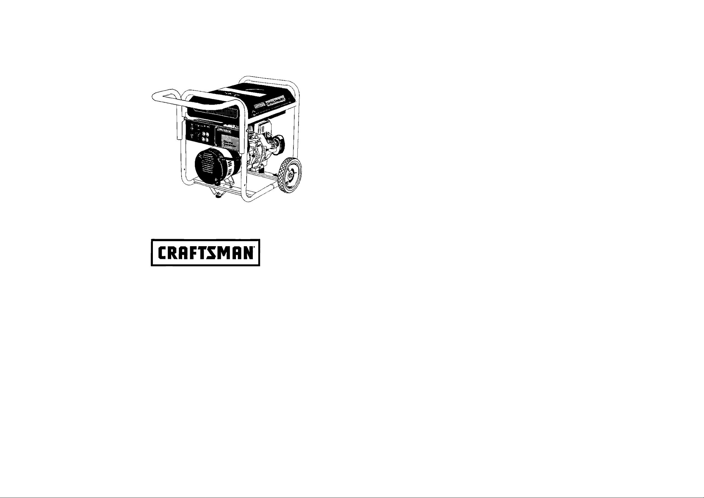
Model No.
919.679501
120/240 VOLT • 5000 WATT
GENERATOR
IMPORTANT:
Read the Safety Guidelines
and All Instructions Carefully
Before Operating
Sold by Sears Canada, Inc., Toronto, Ont. M5B2B8
MGP-B79S01 11/9/99
• SAFETY GUIDELINES
• ASSEMBLY
• OPERATION
• MAINTENANCE
• TROUBLESHOOTING
• REPAIR PARTS
Page 2

TABLE OF CONTENTS
Warranty
Safety Guidelines
Assembly
.........................................................
.......................................
.....................................................
3-8
9-10
Operation.................................................11-14
Maintenance............................................14-16
Service Adjustments
DATE PURCHASED:
MODELND:
SERIAL NO:
STORE WHERE PURCHASED:
ADDRESS:
CITY:
TELEPHONE:
Record the above information about your unit
so that you will be able to provide it in case of
loss or theft.
________
___________________
...................................
16
2
Storage........................................................17
Troubleshooting Guide
Generator Parts
Engine Parts
EPA Codes
.....................................
.........................................
.............................................
How To Order Parts
..............................
.....................
Back Cover
17
18-20
21 -24
25-26
HORSE POWER 10 HP
GASOLINE CAPACITY
OIL CAPACITY
7 GALLON
26 OZ.
MAINTENANCE AGREEMENT
The Craftsman Warranty, plus a Maintenance Agreement,
provide maximum value for your Sears products. Con
tact your nearest Sears store for details.
CUSTOMER RESPONSIBILITIES
Read and observe the safety rules.
Follow a regular schedule in maintaining, caring for and
using your generator.
Follow the instructions under "Customer Responsibili
ties" and "Storage" sections of this owner's manual.
MGP-679S01
FULL ONE YEAR WARRANTY ON CRAFTSMAN GENERATORS
For one year from the date of purchase, when this Craftsman generator is maintained and operated accord
ing to the instructions in this owner's manual. Sears will repair, free of charge, any defect in material and
workmanship.
If your Craftsman Generator is used for commercial or rental purposes, this warranty applies for only 90
days from the original date of purchase.
FULL ONE YEAR WARRANTY ON CRAFTSMAN ENGINE
For one year from the date of purchase, when this Craftsman engine is maintained and operated according
to the instructions in this owner's manual. Sears will repair, free of charge, any defect in material and
workmanship.
If your Craftsman engine is used for commercial or rental purposes, this warranty applies only for 90 days
form the date of purchase. This warranty does not cover: Expendable items such as spark plugs and air
filters, which become worn during normal use.
Repairs necessary because of operator abuse or negligence, including damage resulting from no oil being
supplied to the engine or failure to maintain the equipment according to the instructions contained in
this owner's manual, are not covered under warranty.
WARRANTY SERVICE IS AVAILABLE BY RETURNING THE GENERATOR TO THE NEAREST SEARS SER
VICE CENTER. This warranty gives you specific legal rights and you may also have other rights, which vary
from PROVINCE TO PROVINCE.
Sold by Sears Canada, Inc., Toronto, Ont.
ENG
Page 3

Page 4
SAFETY GUIDELINES - DEFINITIONS
This manual contains information that is important for you to know and understand. This information relates to
protecting YOUR SAFETY and PREVENTING EQUIPMENT PROBLEMS. To help you recognize this information,
we use the symbols to the right. Please read the manual and pay attention to these sections.
ADANGER
DANGER indicates an imminently hazardous situation
which, if not avoided, will result in death or serious
injury.
___________________________________
AWARNING
WARNING indicates a potentially hazardous situation
which, if not avoided, could result in death of serious
injury.
CAUTION indicates a potentially hazardous situation
which, if not avoided, may result in minor or moderate
irjjury.
CAUTION used without the safety alert symbol indicates a
potentially hazardous situation which, if not avoided, may
result in property damage.
ACAUTION
CAUTION
This product is not equipped with a spark arresting muffler. If the product will be used around flammable
materials, or on land covered with materials such as agricultural crops, forest, brush, grass, or other similar items,
then an approved spark arrester must be installed and is legally required in the state of California. It is a violation
of California statutes section 130050 and/or sections 4442 and 4443 of the California Public Resources Code,
unless the engine is equipped with a spark arrestor, as defined in section 4442, and maintained in effective
working order. Spark arresters are also required on some U. S. Forest service land and may also be legally
required under other statutes and ordinances.
This product may contain chemicals known to the state of California to cause cancer, birth defects, or other
reproductive harm. This warning is given in compliance with California Proposition 65, as detectable amounts of
chemicals subject to proposition 65 may be contained in this product.
IMPORTANT SAFETY INSTRUCTIONS
• SAVE THESE INSTRUCTIONS •
AWARNING
When using this product basic precautions should always be
followed including the following:
RISK OF ELECTROCUTION AND FIRE
HAZARD
Attempting to connect generator
directly to the electrical system of any
building structure.
ADANGER
WHAT COULD HAPPEN
Back feeding electricity through a
building's electrical system to the
outside utility feed lines could en
danger repair persons attempting to
restore service.
Attempting to connect to the incom
ing utility service could result in
electrocution.
Restoration of electrical service while
the generator is connected to the
incoming utility could result in a fire or
serious damage if a isolator switch is
not installed.
Failure to use a double throw transfer
switch when connecting to a
structure's electrical system can
damage appliances and WILL VOID
the manufacturer's warranty.
HOW TO PREVENT IT
Never backfeed electricity through
a structure's electrical system.
To connect to a structure's electri
cal system in a safe manner,
always have a Double-Throw
Transfer Switch installed by a
qualified electrician and in compli
ance with local ordinances. (When
installing a Double-Throw
Transfer Switch, a minimum of
10 gauge wiring must be used.)
3 —ENG
MGP-679501
Page 5

Page 6

READ AND UNDERSTAND ALL WARNINGS BEFORE
ATTEMPTING TO OPERATE GENERATOR.
RISK OF ELECTROCUTION AND FIRE fcont'd)
'^JUi
A DANGER
JK
HAZARD
Operation of generator in rain, wet,
icy, or fiooded conditions.
Use of worn damaged, undersized
or ungrounded extension cords.
Placing generator on or against
highly conductive surface, such as
a steel walkway or metal roof.
WHAT COULD HAPPEN
Water is an excellent conductor of
electricity! Water which comes in
contact with electrically charged
components can transmit electricity to
the frame and other surfaces, resulting
in electrical shock to anyone contact
ing them.
Contact with worn or damaged
extension cords could result in
electrocution.
Use of undersize extension cords
could result in overheating of the
wires or attached items, resulting in
fire.
Use of ungrounded cordsets could
prevent operation of circuit breakers
and result in electrical shock.
Accidental leakage of electrical
current could charge conductive
surfaces in contact with the generator.
HOW TO PREVENT IT
Operate generator in a clean, dry,
well ventilated area. Make sure
hands are dry before touching unit.
Inspect extension cords before
use and replace with new cord if
required.
Use proper size (wire gauge)
cordset for application see chart in
the Assembly section of this
manual.
Always use a cordset having a
grounding wire with an appropriate
grounding plug. DO NOT use an
ungrounded plug.
Place generator on low conductiv
ity surface such as a concrete
slab.
Improper connection of items to
generator.
Operation of unit when damaged,
or with guards or panels removed.
MGP-679S01
Exceeding the load capacity of the
generator by attaching too many
items, or items with very high load
ratings to it could result in overheating
of some items or their attachment
wiring resulting in fire or electrical
shock.
Attempting to use the unit when it has
been damaged, or when it is not
functioning normally could result in
fire or electrocution.
Removal of guarding could expose
electrically charged components and
result in electrocution.
4 —ENG
ALWAYS operate generator a
minimum of six feet from any
conductive surface.
Read the load rating chart and
instructions in the Wattage Calcu
lation section. Make sure that the
summation of electrical loads for
all attachments does not exceed
the load rating of the generator.
Do not operate generator with
mechanical or electrical problem.
Have unit repaired by an Autho
rized Service Center.
Do not operate generator with
protective guarding removed.
Page 7

Page 8

READ AND UNDERSTAND ALL WARNINGS BEFORE
ATTEMPTING TO OPERATE GENERATOR.
AWARNING
RISK OF FIRE
HAZARD WHAT COULD HAPPEN
Attempting to fill the fuel tank while
the engine is running.
Sparks, fire, hot objects
Improper storage of fuel Improperly stored fuel could lead to ac
Inadequate ventilation for generator Materials placed against or near the
Gasoline and gasoiine vapors can
become ignited by coming in contact
with hot components such as the
muffier, engine exhaust gases, or from
an eiectricai spark.
Cigarettes, sparks, fires, or other hot
objects can cause gasoline or gaso
line vapors to ignite.
cidental ignition. Fuei improperiy se
cured couid get into the hands of chiidren or other unquaiified persons.
generator or operating the generator in
areas where the temperature exceeds
104° F. ambient (such as storage rooms
or garages) can interfere with its proper
ventilation features causing overheat
ing and possibie ignition of the materiais or buiidings.
HOW TO PREVENT IT
Turn engine off and aliow it to cooi
before adding fuei to the tank. Equip
area of operation with a fire extin
guisher certified to handle gasoline
or fuei fires.
Add fuel to tank in weii ventiiated
area. Make sure there are no
sources of ignition near the genera
tor.
Store fuei in a OSHA approved con
tainer designed to hoid gasoiine.
Store container in secure location to
prevent use by others.
Operate generator in a ciean, dry,
weii ventiiated area a minimum of
four feet from any buiiding, object
or waii, DO NOT OPERATE UNIT
INDOORS OR IN ANY CONFINED
AREA.
Tampering with factory set engine
speed settings.
Overfiiiing the fuei tank - fuel spill
age.
Engine speed has been factory set to
provide safe operation. Tampering with
the engine speed adjustment couid re
sult in overheating of attachments and
couid cause a fire.
Spiiied fuel and its vapors can become
ignited from hot surfaces or sparks.
5 — ENG
Never attempt to "speed-up" the
engine to obtain more performance.
Both the output voitage and fre
quency wili be thrown out of stan
dard by this practice, endangering
attachments and the user.
Use care in fiiiing the tank to avoid
spiiling fuei. Make sure fuei cap is
secured tightly and check engine
for fuel leaks before starting
engine. Move generator away
from refueiing area or any spiiiage
before starting engine. Aiiow for
fuei expansion. Keep maximum
fuei ievei Vi inch beiow the tip of
the fuel tank. Never refuel with the
engine running.
MGP-679501
Page 9

Page 10
READ AND UNDERSTAND ALL WARNINGS BEFORE
ATTEMPTING TO OPERATE GENERATOR.
A DANGER
Risk of Injury and Property Damage When
Transporting Generator
HAZARD
Fire, Inhalation, Damage to
Vehicle Surfaces
RISK OF BREATHING - INHALATION HAZARD
WHAT COULD HAPPEN
Fuel or oil can leak or spill and could
result in fire or breathing hazard, seri
ous injury or death can result. Fuel or
oil leaks will damage carpet, paint or
other surfaces in vehicles or trailers.
A DANGER
HOW TO PREVENT IT
If generator is equipped with a fuel
shut-off valve, turn the valve to the
off position before transporting to
avoid fuel leaks. If generator is not
equipped with a fuel shut-off valve,
drain the fuel from tank before trans
porting. Transport fuel only in an
OSHA approved container. Always
place generator on a protective mat
when transporting to protect against
damage to vehicie from leaks. Re
move generator from vehicle imme
diately upon arrival at your destina
tion
HAZARD WHAT COULD HAPPEN
Gasoline engines produce toxic car
bon monoxide exhaust fumes.
MGP’679S01
Breathing exhaust fumes will cause se
rious injury or death.
HOW TO PREVENT IT
Operate generator in clean, dry, well
ventilated area. Never operate unit
in enclosed areas such as garages,
basements, storage, sheds, or in
any location occupied by humans or
animals. Keep children, pets and
others away from area of operating
unit.
6 — ENG
Page 11

Page 12

READ AND UNDERSTAND ALL WARNINGS BEFORE
ATTEMPTING TO OPERATE GENERATOR.
AWARNING
RISK OF UNSAFE OPERATION
HAZARD
Operation of generator in careless
manner.
Operation of voltage sensitive appli
ances without a voltage surge pro
tector.
WHAT COULD HAPPEN HOW TO PREVENT IT
All sources of energy include the po
tential for injury. Unsafe operation or
maintenance of your generator could
lead to serious injury or death to you or
others.
Any gasoline operated household gen
erator will incur voltage variations caus
ing damage to voltage sensitive appli
ances or could result in fire.
• Review and understand all of
the operating instructions and
warnings in this manual.
• Become familiar with the
operation and controls of the
generator. Know how to shut it
off quickly.
• Equip area of operation with a
fire extinguisher certified to
handle gasoline or fuel fires.
• Keep children or others away
from the generator at all times.
Always use a U.L. listed voltage sen
sitive surge protector to connect
voltage sensitive appliances (TV,
computer, stereo, etc.). Failure to
use a U.L. listed voltage surge
protector will void the warranty on
your generator.
Notice; A multiple outlet strip is not
a surge protector make sure you use
a U.L. listed voltage surge protec
tor.
Raising or suspending generators
equipped with lift rings improperly
Operating generator while sus
pended
Generator could fall causing serious in
jury or death to you or others.
Improper raising or suspending can
cause damage to the generator.
Generator will not operate properly and
will cause damage to the generator and
could cause serious injury or death to
you or others.
7 —ENG
Always use proper connecting pro
cedures as described in this manual
when connecting cables, chains, or
straps for raising or suspending gen
erators equipped with lift rings.
Always use cables, chains, or straps
rated at 2000 lbs working load or
more to raise or suspend generator.
Never operate generator while sus
pended or in an unlevel position.
Always operate generate on a flat,
level surface.
MCP-679S01
Page 13

Page 14

READ AND UNDERSTAND ALL WARNINGS BEFORE
ATTEMPTING TO OPERATE GENERATOR.
AWARNING
RISK OF HOT SURFACES
HAZARD
Contact with hot engine and genera
tor components.
HAZARD
Contact with moving parts can re
sult in serious injury.
WHAT COULD HAPPEN HOW TO PREVENT IT
Contact with hot surfaces, such as en
gines exhaust components, could re
sult in serious burns.
During operation, touch only the
control surfaces of the generator.
Keep children away from the gen
erator at all times. They may not be
able to recognize the hazards of this
product.
AWARNING
RISK OF MOVING PARTS
WHAT COULD HAPPEN HOW TO PREVENT IT
The generator contains parts which ro
tate at high speed during operation.
These parts are covered by guarding
to prevent injury.
Never operate generator with guard
ing or cover plates removed. Avoid
wearing loose fitting clothing orjewelry which could be caught by mov
ing parts.
HAZARD
Lifting a very heavy object.
AWARNING
RISK FROM LIFTING
WHAT COULD HAPPEN
Serious injury can result from attempt
ing to lift too heavy an object.
8 — ENG
HOW TO PREVENT IT
The generator is too heavy to be
lifted by one person. Obtain assis
tance from others before you try to
move it.
Page 15

Page 16

CARTON CONTENTS
ASSEMBLY
2 - Shoulder
Bolts
1 - Owner's Manual
1 - Foot Bracket
2 - Handle Caps
Read owner's manual. Do not attempt to operate equipment until you have read Owner’s
ACAUTION
Manual for Safety, Assembly, Operation, Maintenance, Storage Instructions.
TOOLS NEEDED FOR ASSEMBLY
1 - Box Cutter or Knife
2-9/16 " Wrenches
2 - 1/2" Wrenches
1 -1" thick X 1 ’ square piece of wood
REMOVE GENERATOR FROM CARTON
• Open carton from top,
• Cut carton along dotted lines.
• Remove all carton inserts.
• Remove generator through opening in carton.
• Using a 9/16 inch socket remove shipping block
from under the generator head. Unscrew the bolt
and remove the wood block. NOTE: It is very
important that this is removed before starting your
generator.
IMPORTANT: Before any attempt to start your genera
tor be sure to check engine oil (See Adding Engine Oil
paragraph in the Operation section on page 13 of this
manual.)
1 - Isolator Foot
' 5.16-18 X 1 3/4 '
Cap Screws
6-5/16-18x3.4 "
Cap Screws
2 - Washers
9 - 5/16-18
Lock Nuts
2 - 3/8-16
Lock Nuts
9 —ENG
MGP-S79S01
Page 17

Page 18

GROUNDING THE GENERATOR
A grounding lug is supplied with the generator for use
when required by local electrical ordinances. Refer to
article 250 of the National Electrical Code to clarity
any needed grounding information. Your local electric
company or a certified electrician should be able to
help you with this information.
Grounding Lug
NOTE: Your engine is already grounded to the frame
by a grounding strap.
INSTALLING WHEEL KIT
The Craftsman Wheel Kit was designed to greatly
improve the portability of your generator.
ACAUTION
Drain gas and oil before
i assembling the portability
kit. Failure to do so will cause damage to the
engine.
NOTE: Always follow state regulations for proper oil
disposal.
• Place generator on level ground; drain all gas and
oil from the engine (see engine manual for correct
procedure).
• Place a 1" thick x 1' square piece of wood on the
ground in front of the engine. With the help of
another person, tilt the generator and rest the
recoil starter on the wood. NOTE: This will
support the gasoline engine during assembly and
make assembly easier.
• Place a handle cap (7) onto each end of handle
prior to installation.
• The handle should be installed on the electrical
outlet end of the generator. Place one washer
(12) on long cap screws (11). Align the handle
brackets with the upper holes pre-drilled in the
generator frame. Place mentioned screws through
frame and handle brackets. Secure with lock nuts
(8) and tighten.
• Locate the engine support. Place one wheel
bracket (4) on top of support as shown in illustra
tion. Align with the pre-drilled holes in support.
Place 2 cap screws (9) through holes in bracket
and support. Secure with 2 lock nuts (8) and
tighten.
• Insert one shoulder bolt (2) into wheel (1). Insert
threaded end of bolt through wheel bracket,
secure with lock nut (3) and tighten. NOTE: The
wheel will not rub frame if installed properly.
MCP-679S01
10-
Page 19

Repeat the above steps for the opposite side.
Insert the threaded stud of rubber foot (10)
through the middle hole of the foot bracket (5).
Secure with lock nut (8) and tighten.
Locate the support under the electrical outlet end
of the generator. Position foot bracket (5), with
rubber foot installed, under the support and align
the holes in the foot bracket (5) with the slots in
the support. Place one cap screw (9) through each
slot in the support and the holes in the foot
bracket. Secure with the lock nuts (8) and tighten.
Once completed, the wheel kit is ready for use.
Key
No.
1
2
Description PART NO.
Wheel (2 used)
AC-0014
Shoulder Bolt (2 used) CAC-60
3 Lock Nut 3/8"-16 (2 used) SSF-8111-ZN
4
5
6
7
8 Lock Nut 5/16"-18(9 used)
9
Wheel Bracket (2 used) GS-0561
Foot Bracket GS-0562
Handle GS-0564
Handle Cap (2 used) GS-0565
SSF-8150
Cap Screw 5/16"-18 x 3/4"
(6 used) SS-12-CD
10 Isolator Foot GS-0587
11
12 Washer (2 used)
-ENG
Cap Screw 5/16-18x1.75"
(2 used)
SSF-999-1
SS-6506-CD
Page 20

OPERATION
KNOW YOUR GENERATOR
Read this Owner's Manual and Safety Rules before operation of your Generator. Compare this illustra
tion with your generator to familiarize yourself with the location of various controls and adjustments. Save the
manual for future references.
FUEL CAP
FUELTANK
ENGINE RUN/STOP
SWITCH
120 VOLT RECEPTACLES
AIR CLEANER
240 VOLT RECEPTACLI
CIRCUIT breaker;
FUEL TANK- Capacity of 7 US gallons.
CHOKE SWITCH- Lever used to start cold engine.
ENGINE RUN/STOP SWITCH- Sets engine in starting
mode for recoil starter - Stops running engine.
ENGINE OIL FILL- Place where engine oil is poured.
CIRCUIT BREAKER- Each receptacle has a circuit
breaker to protect the generator from overloading.
120 VOLT RECEPTACLES- Used to supply 1800 watts
of electrical power per receptacle or a combination of
3600 watts on the 120 side for operations. Protected by
15 amp circuit breaker.
CHOKE SWITCH
ENGINE OIL FILL
RECEPTACLES
Your generator is equipped with duplex 120 volt recep
tacles and a twistlock 240 volt receptacle.
The unit is also equipped with a 15 amp circuit breaker
for the 120 volt receptacles and a 20 amp circuit breaker
for the 240 volt receptacle which is provided to protect
the generator against electrical overload. If the circuit
breaker trips, unplug electrical load from receptacle. Let
circuit breaker cool down and then push circuit breaker
button to reset.
240 VOLT TWISTLOCK RECEPTACLE- Used to
supply 5000 watts of electrical power per receptacle for
operations. Protected by 20 amp circuit breaker.
AIR CLEANER- Includes filter element and foam
pre-cleaner that limits the amount of dirt that enters
the engine.
11 — ENG
MGP-679S01
Page 21

Page 22

LOW OIL SHUTDOWN
Your Craftsman generator engine is equipped with
Low Oil Shutdown. Low Oil Shutdown is a safety
device designed to protect your engine from damage
in the event the oil level in the crankcase is low.
If while the engine is running, the oil gets low, it will
automatically shut itself down and will not restart until
the oil is added. If the oil is low before start-up, the
generator will not start until oil is added.
NOTE: The Low Oil Shutdown mechanism is very sen
sitive. You must fiil the engine to the full mark on the
dipstick to inactivate this safety device.
GENERATOR CAPACITY
Exceeding the rated capacity of your generator can
result in serious damage to your generator and
connected electrical devices. You should observe the
following to prevent overloading the unit:
• Starting and running wattage requirements should
always be calculated when matching a generators
wattage capacity to the appliance or tool.
• There are two types of electrical appliances that
can be powered by your generator:
A. Items such as radios, light bulbs, television
sets, and microwaves have a "resistive load".
Starting wattage and running wattage are the
same.
B. Items such as refrigerators, air compressors,
washer, dryer, and hand tools that use an
electrical motor have an "inductive load".
Inductive load appliances and tools require
approximately 2 to 4 times the listed wattage
for starting the equipment. This initial load
only lasts for a few seconds on start-up but is
very important when figuring your total
wattage to be used.
NOTE: Some inductive appliances and tools will list
on the motor name plate, the starting and running
voltage and amperage requirements. Use the follow
ing formula to convert voltage and amperage to
wattage: (Volts X Amp = Watts)
• Always start your largest electric motor first, and
then plug in other items, one at a time.
NOTE: On 120-volt loads the maximum starting watt
age should NOT exceed one half of the rated generator
wattage. Example: a 5000 rated wattage generator =
2500 maximum starting wattage.
The guide is provided to assist you in determining the
appliances and tools that can be ran with the wattage
capacity of your generator.
MGP'679S01
12-
Page 23

Appitcaition Qui<ie
To ill» J<t>r year
(rfKtw Atwns tA« *wn« tim».
yrt98B|№ ytftiWiFii tfWiWW 4irfr MWiCSMV. -rttBy fflfy
wiW dMlimwW. Bhw*t e# flwrttwii^^
OBTAINING ELECTRICITY FROM GENERATOR
There are basically two ways to obtain electricity form
a generator:
• Use of extension cords directly from the genera
tor to the appliance, lights, tools, etc.
• Use of a double-throw transfer switch installed
directly to the main electrical supply outside of
the house.
Extension Cord
When using an appliance or tool at a considerable
distance from the generator, a 3-wire extension cord
that has a 3-blade grounding plug and a 3-slot
receptacle that accepts the tool's plug MUST be
used in order to reduce the risk of electrical shock. A
cord of adequate size must be used. A minimum of 12
gauge wire size with at least a 20 amp draw can be
used. When amperage exceeds 20 amps a 10 gauge
wire size should be used.
AWARNING
Repair or replace damaged extension cords
immediately.
An extension cord that is hot
to the touch is overloaded.
-ENG
Page 24

Connecting Generator To Main Electrical
Supply
Potential hazards exist when a electrical generator is
connected to the main electrical supply coming into
the house. It is at that point that the generator could
feed back into the utility company's system causing
possible electrocution of workers who are repairing
electrical lines. To avoid back feeding of electricity into
utility systems, a double-throw transfer switch
should be installed between the generator and utility
power. This device should be installed by a licensed
electrician and in compliance with all local electrical
codes.
NOTE: When installing a Double-Throw Transfer
Switch, a minimum of 10 gauge wiring must be used.
BEFORE STARTING ENGINE
ACAUTION
engine low of oil or out of oil could result in
serious damage to the engine.
Adding Engine Oil
Your generator has been shipped without oil in the
engine. Begin by removing the oil dipstick and plug.
Start pouring the oil in slowly.
The engine will hold approximately 26 ounces of oil. To
check the oil, clean and replace the dipstick. Do not
screw the dip stick in when checking the oil level. Next,
remove the dipstick to check the level. The oil dipstick
is clearly marked with lines that tell you when the
engine has enough oil. Do not fill above this point.
I Always check engine oil level
I before every start. Running
NOTE: When adding oil to the engine crankcase, use a
high quality detergent oil classified "For Service
SF,SG,SH" rated SAE 30 weight. Use no special additives.
Select the oil's viscosity grade according to your expected
operating temperatures.
SAE Viscosity Grades
Gasoline
Your generator engine is 4 cycle. Use unleaded fuel
only. Never mix oil with gasoline.
13-
Page 25

• Remove gas cap.
• Add unleaded gasoline, slowly, to fuel tank.
Use clean, fresh, regular unleaded gasoline with a
minimum of 85 octane. Do not mix oil with gasoline.
ACAUTION
below the bottom of the Filler neck to provide
space for fuel expansion. Wipe any fuel spillage
from engine and equipment before starting
engine.
Do not overfill.
AWARNING
engine is running or hot. Do not smoke when
filling fuel tank.
Never fill fuel tank com
pletely. Fill tank to 1/2"
I
Never fill fuel tank indoors.
Never fill fuel tank when
To Start Your Generator
ACAUTION
areas. Engine exhaust contains carbon monox
ide, an ordoiiess and deadly gas.
Open the fuel shut-off valve. Turn counter clock
wise until the valve stops.
I Never run engine indoors or
I in enclosed, poor ventilated
On the engine there is a ON/OFF switch located on
the front panel of the engine. Place this switch to
• Move the choke control located on the engine to
"FULL CHOKE" position.
NOTE: No choke is required on warm engines. Make
sure choke is in the "NO CHOKE " position on warm
CftOKS LEVM
HO CHOKE
potmoM
- ENG
MGP-679S01
Page 26

ACAUTION
[engine starts.
You MUST unplug any load
from the generator before starting to prevent
permanent damage to any appliances.
_________
• Grasp handle on rope starter and pull slowly until
resistance is felt. Let the rope rewind slowly. Pull
rope with a rapid full arm stroke. Let rope rewind
slowly. Repeat if necessary.
NOTE: IF ENGINE OIL LEVEL IS TOO LOW, EN
GINE WILL NOT START. CHECK OIL LEVEL AND
ADD IF NECESSARY.
• When engine starts, gradually move the choke to
the "NO CHOKE" position.
IMPORTANT: Allow generator to run at no load for 5
minutes upon each initial start-up to allow engine and
generator to stabilize.
STOPPING ENGINE
• Disconnect all electrical loads.
• Turn ON/OFF switch to "STOP" position.
• Close fuel shut-off valve.
IMPORTANT: Never store engine with fuel in tank,
indoors, or in enclosed, poorly ventilated areas or
where fuel fumes may reach an open flame.
CONNECTING ELECTRICAL LOADS
• Let engine run and warm up for five minutes after
starting with no electrical load.
Connect loads in the following manner to prevent
damage to equipment:
• Connect inductive load equipment first, inductive
loads consist of refrigerators, freezers, water
pumps, air conditioners, or small hand tools.
Connect the items that require the most wattage
first.
• Connect the lights next.
• Voltage sensitive equipment should be the last
equipment connected to the generator. Plug
voltage sensitive appliances such at TV's, VCR's,
microwaves, ovens, computers, and cordless
telephones into a UL listed voltage surge protec
tor, then connect the UL listed voltage surge
protector to the generator.
IMPORTANT: You should always add up the rated
watts of all lights, tools and appliances you are
powering at one time. This total should not
exceed the rated capacity of you generator or
circuit breaker rating of the receptacle supplying
power.
________________
MAINTENANCE
CUSTOMER RESPONSIBILITIES TABLE
Before each
use
MAINTENANCE TASK
Check oil level
Change oil
Clean Air Filter Assembly
Check Spark Plug
Prepare Unit for Storage
X See Note 2
Prepare unit for storage if it is to remain idle for more than 30 days.
Note 1: Change oil after first two (2) operating hours and every 50 operating hours thereafter, more often if operated
in extreme dusty or dirty conditions.
Note 2: Check oil after 5 hours of operation (See the Oil paragraph on page 15 of this section)
Every 25
Hours of Every
Season
X
X
Every 50
Hours of Every
Season
See Note 1
Every 100
Hours of Every
Season
X
MGP-B79S01
14 —ENG
Page 27

Page 28

GENERAL RECOMMENDATIONS
The warranty of the generator does not cover items
that have been subjected to operator abuse or negli
gence. To receive full value from the warranty, opera
tor must maintain the generator as instructed in this
manual.
Some adjustments will need to be made periodically to
maintain your generator.
GENERATOR MAINTENANCE
Your generator should be kept clean and dry at all
times. The generator should not be stored or oper
ated in environments that include excessive moisture,
dust or any corrosive vapors. If these substances are
on the generator, clean with a cloth or soft bristle
brush, Do not use a garden hose or anything with
water pressure to clean the generator. Water may
enter the cooling air slots and could possibly damage
the rotor, stator and the internal windings of the
generator head.
All adjustments in the Maintenance section of this
manual should be made at least once each season.
ENGINE MAINTENANCE
NOTICE: Maintenance, replacement or repair of
the emission control devices and systems may be
performed by any nonroad engine repair establish
ment or individual. However, to obtain no charge
repairs under the terms and provisions of the
engine manufacturers warranty statement, any
service or emission control part repair or replace
ment must be performed by a factory authorized
dealer.
Oil
• Oil level should be checked prior to each use and
at least every 5 hours of operation. To check oil
Adding Engine Oil paragraph in the Operation
see
section on page 13.
Changing Engine Oil
For a new engine, change oil after the first 2 operating
hours. Thereafter, change oil after every 50 hours of
operation.
Change the oil while the engine is still warm. The oil
will flow freely and carry away more impurities. Make
sure the engine is level when filling, checking or
changing oil.
Change the oil as follows:
• To keep dirt, grass clippings, etc. out of the
engine, clean the area around the drain plug and
dipstickbefore removing it.
• Remove the oil drain plug and dipstick. Tilt the
engine slightly towards the oil drain to obtain
better drainage. Be sure to allow ample time for
complete drainage.
15-
Page 29

Reinstall the drain plug. Make sure it is tightened
securely.
Fill the crankcase with new oil of the proper type
(See Adding Engine Oil in the Operation Section),
to the Full mark on the dipstick. Always check the
level with the dipstick before adding more oil.
• Reinstall the oil fill cap or plug and tighten se
curely.
Service Air Cleaner
NOTE: Do not use petroleum solvents, e.g., kerosene,
which will cause the cartridge to deteriorate. Do not
use pressurized air to clean cartridge. Pressurized air
can damage the cartridge.
To service air cleaner follow these steps:
• Unscrew wing nut. Remove cover and air cleaner
cartridge.
• Remove cartridge from cover.
To service cartridge, clean by tapping gently on a flat
service. Do not oil cartridge. Replace if dirty or dam
aged.
• Replace air cleaner cartridge. Place cover over
cartridge and tighten nut finger tight and then turn
it one more complete turn.
-ENG
BASE
PAPER FILTER
COVER
WING NUT
MGP-S79S01
Page 30

Clean Guard/Muffler
Do not clean with a forceful spray of water because
water could contaminate fuel system. With a brush or
cloth clean finger guard after every use to prevent
engine damage caused by overheating. Before running
engine, clean muffler area to remove all combustible
debris.
Clean and Replace Spark Plug
Check spark plug yearly or every 100 operating hours.
• Clean area around spark plug.
• Remove and inspect spark plug.
• Replace spark plug if electrodes are pitted, burned
or porcelain is cracked. For replacement use
Champion RJ17LM resistor spark plug.
• Check electrode gap with wire feeier gauge and
set gap .030 if necessary.
• Install spark, tighten securely.
.030’ (0.76MM)
WIRE GAUGE
SERVICE ADJUSTMENTS
CARBURETOR
The carburetor of your generator is pre-set at the fac
tory. The carburetor should not be tampered with. If your
generator is used at an altitude in excess of 4000 feet
performance may be affected. If so consult with your
nearest Craftsman Service Center regarding high altitude
set changes.
GOVERNOR
Your engine governor maintains the constant operating
speed of your generator. DO NOT tamper with the en
gine governor which is factory set for proper engine
speed.
Over-speeding your engine above factory high speed set
ting can be dangerous and could possibly cause per
sonal injury or property damage. If you believe the en
gine is running too fast or slow, take your generator to a
Authorized Craftsman Service Center for repair and ad
justment.
ACAUTION
when sufficient power is not available the engine
life could be shortened.
I Low engine speeds impose a
I heavy load on the engine and
MGP-679S01
16 — ENG
Page 31

Page 32

STORAGE
If you are going to store your generator for more than
30 days, use the following information as a guide to
prepare the generator for storage.
ACAUTION
in enclosed, poorly ventilated areas, where
fumes can reach an open flame, spark or pilot
light as on a furnace, water heater, clothes
dryer or other gas appliances.
Never store generator with
I fuel in the tank indoors or
Engine Preparation
• Add fuel stabilizer to fuel tank to minimize the
formation of fuel gum deposits during storage.
• Run engine at least 10 minutes after adding
stabilizer to allow it to enter the fuel system.
TROUBLESHOOTING GUIDE
PROBLEM
CAUSE
• Disconnect the spark plug wire and remove the
spark plug.
• Add one teaspoon of oil through the spark plug
hole.
• Place rag over spark plug hole and pull the recoil a
few times to lubricate the combustion chamber.
Replace the spark plug, but do not connect the
spark plug wire.
NOTE; If a fuel stabilizer is not used, all gasoline must
be drained from the tank and carburetor to prevent gum
deposits from forming on these parts and causing pos-;
sible malfunction of the engine.
Generator
• Clean the generator as outlined in the Generator
Maintenance paragraph on page 15.
• Check that cooling air slots and openings on
generator are open and unobstructed.
CORRECTION
Engine will not start
No electrical output
Repeated circuit breaker trip
ping
Generator overheating the
circuit breaker depressed
1. Low on fuel or oil.
2. Ignition switch in "Off" position.
3. Faulty spark plug.
4. Choke in wrong position.
5. Fuel shut-off valve in closed
position.
6. Unit loaded during start-up.
7. Spark plug wire loose.
1. Faulty receptacle.
2. Circuit breaker kicked out.
3. Defective capacitor.
4. Faulty power cord.
1. Overload
2. Faulty cords or equipment.
1. Generator overloaded.
2. Insufficient ventilation.
17 —ENG
1. Add fuel or oil.
2. Turn to "ON" position
3. Replace spark plug.
4. Adjust choke accordingly.
5. Open fuel shut-off valve.
6. Remove load from unit.
7. Attach wire to spark plug.
1. Have Authorized Sears Service
Center replace.
2. Depress and reset.
3. Have Authorized Sears Service
Center replace capacitor.
4. Repair or replace cord.
1. Reduce load.
2. Check for damaged, bare, or
frayed wires on equipment.
Replace.
1. Reduce load.
2. Move to adequate supply of
fresh air.
MGP-679S01
Page 33

Page 34

CALIFORNIA & US EPA EMISSION CONTROL WARRANTY STATEMENT
The U. S. Environmental Protection Agency fEPA*), the California Air Resources Board CCARB") and Tecumseh Products Co.
are pleased to explain the Federal and California Emission Control Systems Warranty on your new utility or lawn and garden
equipment engine. In California, new 1995 and later utility and lawn and garden equipment engines must be designed, built and
equipped to meet the State's stringent anti-smog standards. In other states, new 1997 and later model year engines must be
designed, built and equipped, at the time of sale, to meet the U.S. EPA regulations for small non-road engines. Tecumseh
Products Co. will warrant the emission control system on your utility or lawn and garden equipment engine for the periods of time
listed below, provided there has been no abuse, neglect, unapproved modification, or improper maintenance of your utility or lawn
and garden equipment engine.
Your emission control system may include parts such as the carburetor, ignition system and exhaust system. Also included may
be the compression release system and other emission-related assemblies.
Where a warrantable condition exists, Tecumseh Products Co. will repair your utility or lawn and garden equipment engine at no
cost to you for diagnosis, parts and labor.
MANUFACTURER’S EMISSION CONTROL SYSTEM WARRANTY COVERAGE
Emission control systems on 1995 and later model year California utility and lawn aruf garden equipment engines are warranted
for two years as hereinafter noted. In other states. 1997 and later model year engines are also warranted for two years. If, during
such warranty period, any emission-related part on your engine is defective in materials or workmanship, the part will be repaired
or replaced by Tecumseh Products Co.
OWNER'S WARRANTY RESPONSIBILITIES
As the utility or lavm and garden equipment engine owner, you are responsible for the performance of the required maintenance
listed in your Owner's Manual, but Tecumseh Products Co. will not deny warranty solely due to the lack of receipts or for your
failure to provide written evidence of the performance of all scheduled maintenance.
As the utility or lawn and garden equipment engine owner, you should, however, be aware that Tecumseh Products Co. may
deny you warranty coverage if your utility or lawn and garden equipment or a part thereof has failed due to abuse, neglect,
improper maintenance or unapproved modifications.
You are responsible for presenting your utility or lawn and garden equipment engine to a Tecumseh Authorized Senrice Outlet
(any Tecumseh Registered Service Deafer, Tecumseh Authorized Service Distributor or Tecumseh Central Warehouse Distribu
tor) as soon as a problem exists. The warranty repairs should be completed in a reasonable amount of time, not to exceed 30
days.
Warranty service can be arranged by contacting either a Tecumseh Authorized Service Outlet or by contacting Tecumseh
Products Co., do Service Manager, Engine and Transmission Group Service Division, 900 North Street, Grafton, Wl 53024-1499.
Telephone 1-414-377-2700, or see your local telephone yellow pages under ‘Engines, Gasoline’ for the name, address and
telephone number of a Tecumseh Authorized Service Outlet near you.
IMPORTANT NOTE
This warranty statement explains your rights and obligations under the Emission Control System Warranty (“ECS Wamanty“}
which is provided to you by Tecumseh Products Co. pursuant to California law. Tecumseh Products Co. also provides to original
purchasers of new Tecumseh Products Co. engines. The Tecumseh Products Co. Limited Warranties for New Tecumseh Engine
and Electronic Ignition Modules (“Tecumseh Products Co. Warranty') which is enclosed with all new Tecumseh Products Co.
engines on a separate sheet. The ECS Warranty applies only to the emission control system of your new engine. To the extent
that there is any conflict in terms between the ECS Warranty and the Tecumseh Products Co. Warranty, the ECS Warranty shail
apply except In any drcumstarKss in which the Tecumseh Products Co. Warranty may provide a longer warranty period. Both
the ECS Warranty and the Tecumseh Products Co. Warranty describe important rights and obligations wth respect to your new
engine.
Warranty servk« can only be performed by a Tecumseh Products Co. Authorized Service Outlet, or by Tecumseh Products Co.
at its fadory in Grafton, Wl. At the time of requesting warranty service, evidence must be presented of the date of sale to the
original purchaser. The purchaser shall pay any charges for making service calls and/or tor transporting the products to and from
the ptaca where the Inspection and/or wananty work is performed. The purchaser shall be responsible tor any damage or loss
Incurred in connection with the transportation of any engine or any part(s) thereof submitted tor inspection and/or wananty work.
If you have any questions regarding your wananty rights and responsibilities, you should contact Tecumseh Products Co. at
1^14-377-2700.
25 —ENG
MGP-S79S01
Page 35

Page 36

EMISSION CONTROL SYSTEM WARRANTY
Emission Control System Warranty (‘ECS Wananty*) for 1995 and later model year California utility and lawn and garden equip
ment engines (for other states, 1997 and later model year engines):
A. APPLICABILITY: This wananty shall apply to 1995 and later model year California utility and lawn and garden equipment
engines (for other states, 1997 and later model year engines). The ECS Warranty Period shall begin on the date the new
engine or equipment is delivered to its original, end-use purchaser, and shall continue for 24 consecutive months thereafter.
B. GENERAL EMISSIONS WARRANTY COVERAGE: Tecumseh Products Co. warrants to the original, end-use purchaser of
the new engine or equipment and to each subsequent purchaser that each of its utility and lawn and garden equipment
engines is;
1. Designed, built and equipped so as to conform with all applicable regulations adopted by the Air Resources Board pursuant
to its authority in Chapters 1 and 2, Part 5, Division 26 of the Health and Safety Code, and
2. Free from defects in materials and workmanship which, at any time during the ECS Warranty Period, will cause a warranted
emissions-related part to fail to be identical in all material respects to the part as described in the engine manufacturer's
application for certification.
C. The ECS Warranty only pertains to emissions-related parts on your engine, as follows;
1. Any warranted, emissions-related parts which are not scheduled for replacement as required maintenance in the Owner's
Manual shall be warranted for the ECS Warranty Period. If any such part fails during the ECS Warranty Period, it shall be
repaired or replaced by Tecumseh Products Co. according to Subsection 4 below. Any such part repaired or replaced
under the ECS Warranty shall be warranted for any remainder of the ECS Warranty Period.
2. Any warranted, emissions-related pert which is scheduled only for regular inspection as specified in the Owner's Manual
shall be warranted for the ECS Warranty Period. A statement in such written instructions to the effect of ‘repair or replace
as necessary’, shall not reduce the ECS Warranty Period. Any surdi part repaired or replaced under the ECS Warranty
shall be warranted for the remainder of the ECS Warranty Period.
3. Any warranted, emissions-related part which is scheduled for replacement as required maintenance in the Owner's Manual,
shall be warranted for the period of time prior to the first scheduled replacement point for that part. If the part fails prior to
the first scheduled replacement, the part shall be repaired or replaced by Tecumseh Products Co. according to Subsection
4 below. Any such emissions-related part repaired or replaced under the ECS Warranty, shall be warranted for the remain
der of the ECS Warranty Period prior to the first scheduled replacement point for such emissions-related part
4. Repair or replacement of any warranted, emissions-related part under this ECS Warranty shall be performed at no charge to
the owner aTa TecumseTi Authorized Service Outlet.
5. The owner shall not be charged for diagnostic labor which leads to the determination that a part covered by the ECS
Warranty is in fact defective, provided mat such diagnostic wort« is performed at a Tecumseh Authorized Service Outlet.
6. Tecumseh Products Co. shall be liable for damages to other original engine components or approved modifications proximately caused by a failure under warranty of an emission-related part covered by the ECS Warranty.
7. Throughout the ECS Warranty Period, Tecumseh Products Co. shall maintain a supply of warranted emission-related parts
sufficient to meet the expected demand for such emission-related parts.
8. Any Tecumseh Products Co. authorized and approved emission-related replacement part may be used in the performance
of any ECS Warranty maintenance or repair and will be provided without charge to the owner. Such use shall not reduce
Tecumseh Products Co. ECS Warranty obligations.
9. Unapproved add-on or modified parts may not be used to modify or repair a Tecumseh Products Co. engine. Such use
voids this ECS Warranty and Shan be sufficient grounds for disallowing an ECS Warranty claim. Tecumseh Products Co.
shall not be liable hereunder for failures of any warranted parts of a Tecumseh Products Co. engine caused by the use of
such an unapproved add-on or modified part.
.....
EMISSION-RELATED PARTS INCLUDE THE FOLLOWING:
1. Carburetor Assembly and its Internal Components
a) Fuel filter
b) Carburetor gaskets
c) Intake pipe
2. Air Cleaner Assembly
a) Air filter element
Ignition System, including;
a) Spark plug
b) Ignition module
4. Catalytic Muffler (if so equipped)
a) Muffler gasket (if so equipped)
b) Exhaust manifold (if so equipped)
6. Crankcase Breather Assembly and its Components
a) Breather connection tube
MGP-B79501
26 —ENG
Page 37

Page 38

27-ENG
MGP-S7PSÙ7
Page 39

Dear Customer,
In manufacturing this product, many steps have been taken to provide you with the highest quality.
Unfortunately, errors or omissions occasionally occur. In the event that you find a missing or defec
tive part, please contact your nearest Sears store.
SERVICE AND REPAIR PARTS
CALL 1-800-665-4455 *
Keep this number handy should you require a service call or
need to order repair parts.
If ordering parts make sure you have the
name, make and model no. of the merchandise and the name
and number of the part you wish to order.
* If calling locally, please use one of the following numbers;
Regina - 566-5124 Montreal - 333-5740
Toronto - 744-4900 Halifax - 454-2444
Kitchener - 894-7590 Ottawa - 738-4440
Vancouver - 420-8211
If you have any suggestions that would help us to improve our assembly/operation instructions, or
this product, please write them down and mail It to;
Sears Canada Inc.
222 Jarvis Street
Toronto, Ontario
M5B2B8
Attention: Buyer Dept: DB71
NAME
ADDRESS
POSTAL CODE
COMMENTS
PHONE#
Model No,.
MGP’679S01
28 —ENG
Page 40

 Loading...