

Craftsman 919195413 Owner’s Manual
Owner's Manual
{CRAFTSMAN°{
Oil Lubricated
Single Stage
Horizontal Portable
AiR COMPRESSOR
Model No.
919.195413
= Safety Guidelines
= Assembly
= Operation
= Maintenance
= Troubleshooting
= Repair Parts
CAUTION: Read the Safety Guidelines
and All Instructions Carefully Before
Operating.
Sears, Roebuck and Co., Hoffman Estates, IL 60179 U.S.A.
Visit our Craftsman website: www.sears.com/craftsman
N000578 9/6/o7
WARRANTY ................................................ 2
SPECiFiCATiON CHART ...................................... 3
SAFETY GUiDELiNES ...................................... 3-9
GLOSSARY ............................................... 10
ACCESSORIES ............................................ 10
DUTY CYCLE .............................................. 10
ASSEMBLY ............................................ 11-12
iNSTALLATiON ......................................... 13-14
OPERATION ............................................ 15-17
MAINTENANCE ......................................... 18-20
SERVICE AND ADJUSTMENTS ............................ 21-23
STORAGE ................................................ 23
TROUBLESHOOTING GUIDE .............................. 24-27
REPAIR PARTS ......................................... 28-31
ESPAI_OL .............................................. 32-57
NOTES .................................................. 58
REPAIR PROTECTION AGREEMENTS ......................... 59
HOW TO ORDER REPAIR PARTS ...................... Back Cover
ONE YEAR FULL WARRANTY
If this product fails due to a defect in material or workmanship within one year
from the date of purchase, Sears will at its option repair or replace it free of
charge. Contact Sears at 1-800-4-MY-HOME ®to arrange for repair, or return it
to the place of purchase for replacement.
If this product is used for commercial or rental purposes, this warranty applies
for only ninety days from the date of purchase.
This warranty gives you specific legal rights and you may have other rights
which vary from state to state.
Sears, Roebuck and Co., Dept. 817WA, Hoffman Estates, IL 60179
N000578 2-ENG
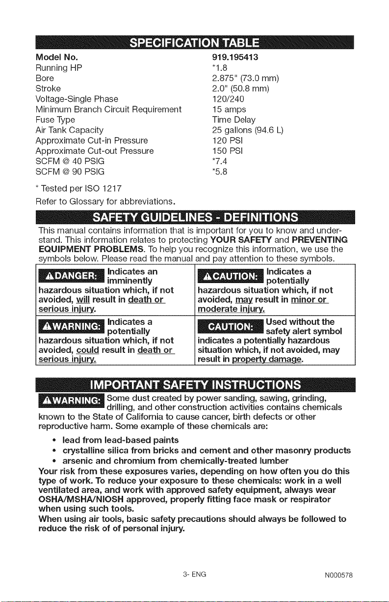
Model No. 919.195413
Running HP "1.8
Bore 2.875" (73.0 mm)
Stroke 2.0" (50.8 mm)
Voltage-Single Phase 120/240
Minimum Branch Circuit Requirement 15 amps
Fuse Type Time Delay
Air Tank Capacity 25 gallons (94.6 L)
Approximate Cut-in Pressure 120 PSi
Approximate Cut-out Pressure 150 PSi
SCFM @40 PSIG *7.4
SCFM @90 PSIG *5.8
* Tested per ISO 1217
Refer to Glossary for abbreviations.
This manual contains information that is important for you to know and under-
stand. This information relates to protecting YOUR SAFETY and PREVENTING
EQUIPMENT PROBLEMS. To help you recognize this information, we use the
symbols below. Please read the manual and pay attention to these symbols.
_ Indicates an
imminently
hazardous situation which, if not
avoided, will result in death or
serious injury.
_ Indicates a
potentially
hazardous situation which, if not
avoided, _ result in minor or
moderate injury,.
_ Indicates a
potentially
hazardous situation which, if not
avoided, could result in death or
serious inNu_13&
Some dust created by power sanding, sawing, grinding,
drilling, and other construction activities contains chemicals
_Used without the
safety alert symbol
indicates a potentially hazardous
situation which, if not avoided, may
result in pLo_pertydamage.
known to the State of California to cause cancer, birth defects or other
reproductive harm. Some example of these chemicals are:
• lead from lead-based paints
crystalline silica from bricks and cement and other masonry products
arsenic and chromium from chemically-treated lumber
Your risk from these exposures varies, depending on how often you do this
type of work. To reduce your exposure to these chemicals: work in a well
ventilated area, and work with approved safety equipment, always wear
OSNA/MSHA/NIOSN approved, properly fitting face mask or respirator
when using such tools.
When using air tools, basic safety precautions should always be followed to
reduce the risk of of personal injury.
3- ENG N000578
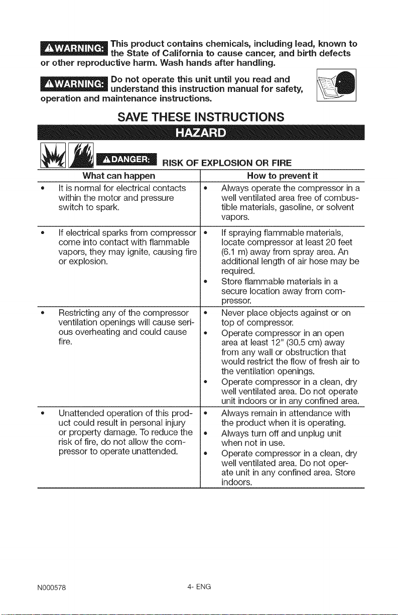
This product contains chemicals, including lead, known to
the State of California to cause cancer, and birth defects
or other reproductive harm. Wash hands after handling.
Do not operate this unit until you read and _A
understand this instruction manual for safety,
operation and maintenance instructions.
SAVE THESE iNSTRUCTiONS
_ RiSK OF EXPLOSION OR FiRE
What can happen
It is normal for electrical contacts
• • Always operate the compressor in a
within the motor and pressure
switch to spark.
• •
If electrical sparks from compressor
come into contact with flammable
vapors, they may ignite, causing fire
or explosion.
• Store flammable materials ina
Restricting any of the compressor
ventilation openings will cause seri-
ous overheating and could cause
fire.
Unattended operation of this prod-
uct could result in personal injury
or property damage. To reduce the
risk of fire, do not allow the com-
pressor to operate unattended.
How to prevent it
well ventilated area free of combus-
tible materials, gasoline, or solvent
vapors.
If spraying flammable materials,
locate compressor at least 20 feet
(6.1 m) away from spray area. An
additional length of air hose may be
required.
secure location away from com-
pressor.
Never place objects against or on
top of compressor.
Operate compressor in an open
area at least 12" (30.5 cm) away
from any wall or obstruction that
would restrict the flow of fresh air to
the ventilation openings.
Operate compressor in a clean, dry
well ventilated area. Do not operate
unit indoors or in any confined area.
Always remain in attendance with
the product when it is operating.
Always turn off and unplug unit
when not in use.
Operate compressor in a clean, dry
well ventilated area. Do not oper-
ate unit in any confined area. Store
indoors.
N000578 4-ENG
__ RISK TO BREATHING (ASPHYXIATION)
What can happen How to prevent it
• The compressed air directly from • Air obtained directly from the com-
your compressor is not safe for pressor should never be used to
breathing. The air stream may con- supply air for human consumption.
tain carbon monoxide, toxic vapors, In order to use air produced by this
or solid particles from the air tank. compressor for breathing, suitable
Breathing these contaminants can filters and in-line safety equipment
cause serious injury or death, must be properly installed. In-line
filters and safety equipment used
in conjunction with the compressor
must be capable of treating air to all
applicable local and federal codes
prior to human consumption.
• Sprayed materials such as paint, • Work in anarea with good cross
paint solvents, paint remover, insec- ventilation. Read and follow the
ticides, weed killers, may contain safety instructions provided on the
harmful vapors and poisons, label or safety data sheets for the
materials you are spraying. Always
use certified safety equipment:
OSHA/MSHA/NIOSH respiratory
protection designed for use with
your specific application.
__ RISK OF SERIOUS INJURY OR PROPERTY DAMAGE
WHEN TRANSPORTING COMPRESSOR
Oil can leak or spill and could
result in fire or breathing hazard;
serious injury or death can result.
oil leaks will damage carpet, paint
or other surfaces in vehicles or
trailers.
Always place compressor on a
protective mat when transport-
ing to protect against damage to
vehicle from leaks. Remove com-
pressor from vehicle immediately
upon arrival at your destination.
_ m D
__ RISK OF BURSTING
Air Tank: The air tank on your Air Compressor is designed and may be UM coded
[for units with air tanks greater than 6" (152.4 mm) diameter] according to ASME
Section VIII, Div. 1 rules. All pressure vessels should be inspected once every two
years. To find your state pressure vessels inspector, look under the Division of Labor
and Industries in the government section of a phone book.
The following conditions could lead to a weakening of the air tank, and result ina
violent air tank explosion:
5- ENG N000578
What can happen How to prevent it
• Failure to properly drain condensed • Drain air tank daily or after each
water from air tank, causing rust use. If air tank develops a leak,
and thinning of the steel air tank. replace it immediately with a new air
Modifications or attempted repairs
to the airtank.
Unauthorized modifications to the • The air tank is designed to with-
safety valve or any other compo- stand specific operating pressures.
nents which control air tank pres- Never make adjustments or parts
sure. substitutions to alter the factory set
Attachments & accessories:
• •
Exceeding the pressure rating of
air tools, spray guns, air operated
accessories, tires, and other inflata-
bles can cause them to explode or
fly apart, and could result in serious
injury.
Tires:
• Over inflationof tirescould result in
serious injury and property damage.
,y,d, " D
tank or replace the entire compres-
sor.
Never drill into, weld, or make any
modifications to the air tank or its
attachments. Never attempt to
repair a damaged or leaking air
tank. Replace with a new air tank.
operating pressures.
Follow the equipment manufactur-
ers recommendation and never
exceed the maximum allowable
pressure rating of attachments.
Never use compressor to inflate
small low pressure objects such as
children's toys, footballs, basket-
balls, etc.
Use a tire pressure gauge to check
the tires pressure before each use
and while inflating tires; see the tire
sidewall for the correct tire pressure.
NOTE: Air tanks, compressors and simi-
lar equipment used to inflate tires can fill
small tires similar to these very rapidly.
Adjust pressure regulator on air supply to
no more than the rating of the tire pres-
sure. Add air insmall increments and
frequently use the tire gauge to prevent
over inflation.
Riskor ELECTRICALS.OCK
What can happen
Your air compressor is powered by
electricity. Like any other electrically
powered device, if it is not used
properly it may cause electric
shock.
N000578 6-ENG
How to prevent it
Never operate the compressor
outdoors when it is raining or in wet
conditions.
Never operate compressor with
protective covers removed or
damaged.
• Repairs attempted by unqualified
personnel can result in serious
injury or death by electrocution.
,, Electrical Grounding: Failure to ,,
provide adequate grounding to
this product could result in serious
injury or death from electrocution.
Refer to "Grounding Instructions"
paragraph in the Installation
section.
Any electrical wiring or repairs
required on this product should be
performed by authorized service
center personnel in accordance with
national and local electrical codes.
Make certain that the electrical
circuit to which the compressor
is connected provides proper
electrical grounding, correct voltage
and adequate fuse protection.
RiSKFROMfLYING
What can happen
The compressed air stream can
cause soft tissue damage to
exposed skin and can propel dirt,
chips, loose particles, and small
objects at high speed, resulting in
property damage or personal injury.
RiSKor.or SURFACES
What can happen
Touching exposed metal such as
the compressor head, engine head,
engine exhaust or outlet tubes, can
result in serious burns.
OBJECTS
How to prevent it
Always wear certified safety equip-
ment: ANSI Z87.1 eye protection
(CAN/CSA Z94.3) with side shields
when using the compressor.
Never point any nozzle or sprayer
toward any part of the body or at
other people or animals.
Always turn the compressor off
and bleed pressure from the air
hose and air tank before attempt-
ing maintenance, attaching tools or
accessories.
How to prevent it
Never touch any exposed metal
parts on compressor during or
immediately after operation.
Compressor will remain hot for
several minutes after operation.
Do not reach around protective
shrouds or attempt maintenance
until unit has been allowed to cool.
7- ENG N000578
RiSKFROMMOVINGPARTS
What can happen
Moving parts such as the pulley, fly-
wheel, and belt can cause serious
injury if they come into contact with
you or your clothing.
• Attempting to operate compressor
with damaged or missing parts or
attempting to repair compressor
with protective shrouds removed
can expose you to moving parts
and can result in serious injury.
[__ RiSK OF UNSAFE OPERATION
What can happen
Unsafe operation of your air com-
pressor could lead to serious injury
or death to you or others.
= Do not operate machine with miss-
How to prevent it
Never operate the compressor with
guards or covers which are dam-
aged or removed.
Keep your hair, clothing, and gloves
away from moving parts. Loose
clothes, jewelry, or long hair can be
caught in moving parts.
Air vents may cover moving parts
and should be avoided as well.
Any repairs required on this product
should be performed by authorized
service center personnel.
How to prevent it
Review and understand all instruc-
tions and warnings in this manual.
Become familiar with the operation
and controls of the air compressor.
Keep operating area clear of all per-
sons, pets, and obstacles.
Keep children away from the air
compressor at all times.
Do not operate the product when
fatigued or under the influence of
alcohol or drugs. Stay alert at all
times.
Never defeat the safety features of
this product.
Equip area of operation with a fire
extinguisher.
ing, broken, or unauthorized parts.
N000578 8-ENG
__ RiSK OF INJURY FROM LiFTiNG
What can happen
• • The compressor is too heavy to be
Serious injury can result from
attempting to lift too heavy an
object.
RISK FROM NOISE
What can happen How to prevent it
Under some conditions and dura- • Always wear certified safety equip-
tion of use, noise from this product ment: ANSI S12.6 (S3.19) hearing
may contribute to hearing loss. protection.
How to prevent it
lifted by one person. Obtain assis-
tance from others before lifting.
SAVE THESE INSTRUCTIONS
FOR FUTURE USE
9- ENG N000578
Become familiar with these terms
before operating the unit.
CFM: Cubic feet per minute.
SCFM: Standard cubic feet per min-
ute; a unit of measure of air delivery.
PSIG: Pounds per square inch gauge;
a unit of measure of pressure.
Code Certification: Products that
bear one or more of the following
marks: UL, CUL, ETL, CETL, have
been evaluated by ©SHA certified
independent safety laboratories and
meet the applicable Standards for
Safety.
Cut=In Pressure: While the motor
low level the motor will restart auto-
matically. The low pressure at which
the motor automatically restarts is
called "cut-in" pressure.
Cut=Out Pressure: When an air com-
pressor is turned on and begins to
run, air pressure in the air tank begins
to build. It builds to a certain high
pressure before the motor automati-
cally shuts off, protecting your air tank
from pressure higher than its capacity.
The high pressure at which the motor
shuts off is called "cut-out" pressure.
Branch Circuit: Circuit carrying elec-
tricity from electrical panel to outlet.
is off, air tank pressure drops as you
continue to use your accessory. When
the tank pressure drops to a certain
This unit is capable of powering the following Accessories. The accessories are
available through the current Power and Hand Tool Catalog or full-line Sears
stores.
Accessories
• In Line Filter
Tire Air Chuck
Quick Connector Sets (various
sizes)
Air Pressure Regulators
Air Hose:l/4" (6.4 mm), 3/8"
(9.5 mm) or 1/2" (12.7 mm) inside
diameter in various lengths
Refer to the selection chart located
on the unit to select the tools this unit
is capable of powering.
Oil Fog Lubricators
This air compressor pump is capable
of running continuously. However,
to prolong the life of your air com-
pressor, it is recommended that a
50%-75% average duty cycle be
N000578 10-ENG
maintained; that is, the air compres-
sor pump should not run more than
30-45 minutes in any given hour.
CONTENTS OF CARTON
1 - Air Compressor
2- Wheels
2 - Shoulder Bolts, 3/8-16
2 - Hex Nuts, 3/8-16
1- Handle
1 - Handle Grip
2 - Cap Screws
2 - 1/4-20 Hex Nuts
2 - Retainer Clips
2 - Flat Washers
2 - Rubber Bumpers
2 - Screws, 1/4-20 x 3/4" (19 ram)
TOOLS REQUIRED FOR
ASSEMBLY
1 - 9/16" (14 ram) socket or open
end wrench
1 - 1/2" (13 ram) socket or open end
wrench
UNPACKING
Remove unit from carton and discard
all packaging. NOTE: Save all parts
bags.
TO iNSTALL HANDLE
The wheels and
handle do not
provide adequate clearance,
stability, or support for pulling the
unit up and down stairs or steps.
The unit must be lifted or pushed
up a ramp. Do not lift the unit by the
manifold assembly; the unit could
be damaged.
1.
To make installation easier, sub-
merge handle grip into warm
soapy water. Remove handle grip
from soapy water and slide onto
handle.
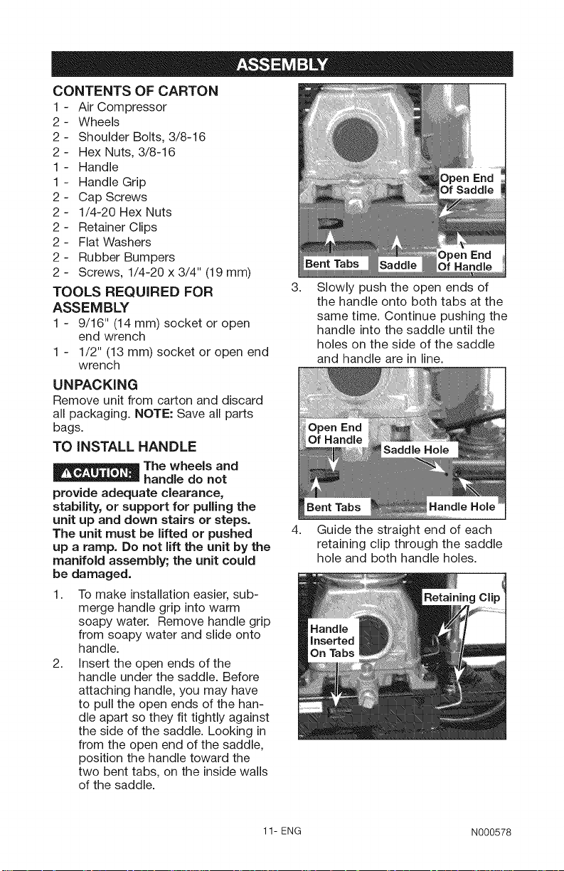
2.
Insert the open ends of the
handle under the saddle. Before
attaching handle, you may have
to pull the open ends of the han-
dle apart so they fit tightly against
the side of the saddle. Looking in
from the open end of the saddle,
position the handle toward the
two bent tabs, on the inside walls
of the saddle.
Open End
Handle
3.
Slowly push the open ends of
the handle onto both tabs at the
same time. Continue pushing the
handle into the saddle until the
holes on the side of the saddle
and handle are in line.
4. Guide the straight end of each
retaining clip through the saddle
hole and both handle holes.
11- ENG N000578
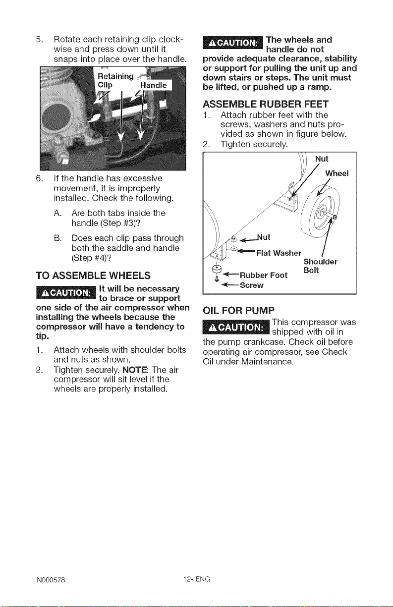
5. Rotate each retaining clip clock-
wise and press down until it
snaps into place over the handle.
6. If the handle has excessive
movement, it is improperly
installed. Check the following.
A. Are both tabs inside the
handle (Step #3)?
B. Does each clip pass through
both the saddle and handle
(Step #4)?
TO ASSEMBLE WHEELS
It will be necessary
to brace or support
one side of the air compressor when
installing the wheels because the
compressor will have a tendency to
tip.
1. Attach wheels with shoulder bolts
and nuts as shown.
2. Tighten securely. NOTE: The air
compressor will sit level if the
wheels are properly installed.
The wheels and
handle do not
provide adequate clearance, stability
or support for pulling the unit up and
down stairs or steps. The unit must
be lifted, or pushed up a ramp.
ASSEMBLE RUBBER FEET
1. Attach rubber feet with the
screws, washers and nuts pro-
vided as shown in figure below.
2. Tighten securely.
Nut
Wheel
OIL FOR PUMP
This compressor was
shipped with oil in
the pump crankcase. Check oil before
operating air compressor, see Check
Oil under Maintenance.
N000578 12-ENG
LOCATION OF THE AIR
COMPRESSOR
• Locate the air compressor in a
clean, dry, and well ventilated
area.
• Place on a solid surface to pre-
vent rocking or tipping.
The air compressor should be
located at least 12" (30.5 cm)
away from the wall or other
obstructions that will interfere
with the flow of air.
The air filter must be kept clear of
obstructions which could reduce
air flow to the air compressor.
The air compressor requires
fresh air flow for proper cool-
ing. DO NOT ALLOW THE
COMPRESSOR TO GET WET.
GROUNDING iNSTRUCTiONS
-- ELECTRICAL
SHOCK. In the event of a short
circuit, grounding reduces the risk
of shock by providing an escape
wire for the electric current. This
air compressor must be properly
grounded.
The portable air compressor is
equipped with a cord having a ground-
ing wire with an appropriate grounding
plug (see following illustrations). The
plug must be used with an outlet that
has been installed and grounded in
accordance with all local codes and
ordinances.
1. The cord set and plug with this
unit contains a grounding pin.
This plug MUST be used with a
grounded outlet.
IMPORTANT: The outlet being used
must be installed and grounded in
accordance with all local codes and
ordinances.
RISK OF
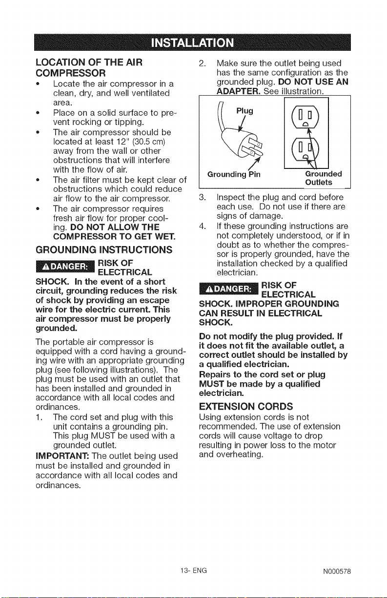
2.
Make sure the outlet being used
has the same configuration as the
grounded plug. DO NOT USE AN
ADAPTER. See illustration.
Plug
Grounding Pin
3.
Inspect the plug and cord before
Grounded
Outlets
each use. Do not use if there are
signs of damage.
4.
If these grounding instructions are
not completely understood, or if in
doubt as to whether the compres-
sor is properly grounded, have the
installation checked by a qualified
electrician.
-- ELECTRICAL
RISK OF
SHOCK. IMPROPER GROUNDING
CAN RESULT iN ELECTRICAL
SHOCK.
Do not modify the plug provided. If
it does not fit the available outlet, a
correct outlet should be installed by
a qualified electrician.
Repairs to the cord set or plug
MUST be made by a qualified
electrician.
EXTENSION CORDS
Using extension cords is not
recommended. The use of extension
cords will cause voltage to drop
resulting in power loss to the motor
and overheating.
13- ENG N000578
Instead of using an extension cord,
increase the working reach of the
air hose by attaching another length
of hose to its end. Attach additional
lengths of hose as needed.
If an extension cord must be used, be
sure it is:
• a 3-wire extension cord that has a
3-blade grounding plug, and a 3-
slot receptacle that will accept the
plug on the product
in good condition
no longer than 50 feet
12 gauge (AWG) or larger. (Wire
size increases as gauge number
decreases. 10 AWG and 8 AWG
may also be used. DO NOT USE
14 OR 16 AWG.)
VOLTAGE AND CiRCUiT
PROTECTION
Refer to the specification chart for the
voltage and minimum branch circuit
requirements.
Risk of Unsafe
Operation. Certain
air compressors can be operated
on a 15 amp circuit if the following
conditions are met.
1. Voltage supply to circuit must
comply with the National
Electrical Code.
2. Circuit is not used to supply any
other electrical needs.
3. Extension cords comply with
specifications.
4. Circuit is equipped with a 15 amp
circuit breaker or 15 amp time
delay fuse. NOTE: If compressor
is connected to a circuit protect-
ed by fuses, use only time delay
fuses. Time delay fuses should be
marked "D" in Canada and "T" in
the US.
If any of the above conditions cannot
be met, or if operation of the compres-
sor repeatedly causes interruption
of the power, it may be necessary to
operate it from a 20 amp circuit. It is
not necessary to change the cord set.
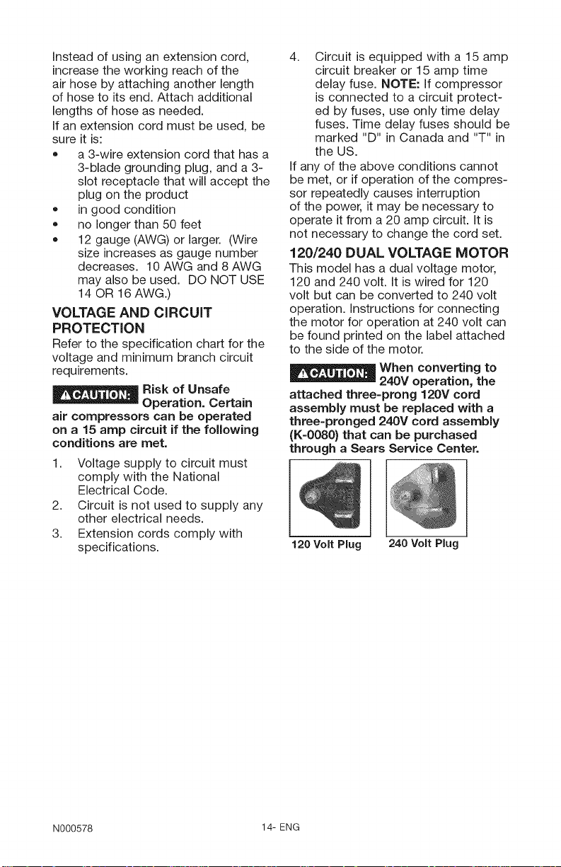
120/240 DUAL VOLTAGE MOTOR
This model has a dual voltage motor,
120 and 240 volt. it is wired for 120
volt but can be converted to 240 volt
operation, instructions for connecting
the motor for operation at 240 volt can
be found printed on the label attached
to the side of the motor.
When converting to
240V operation, the
attached three-prong 120V cord
assembly must be replaced with a
three-pronged 240V cord assembly
(K-0080} that can be purchased
through a Sears Service Center.
120 Volt Plug 240 Volt Plug
N000578 14-ENG
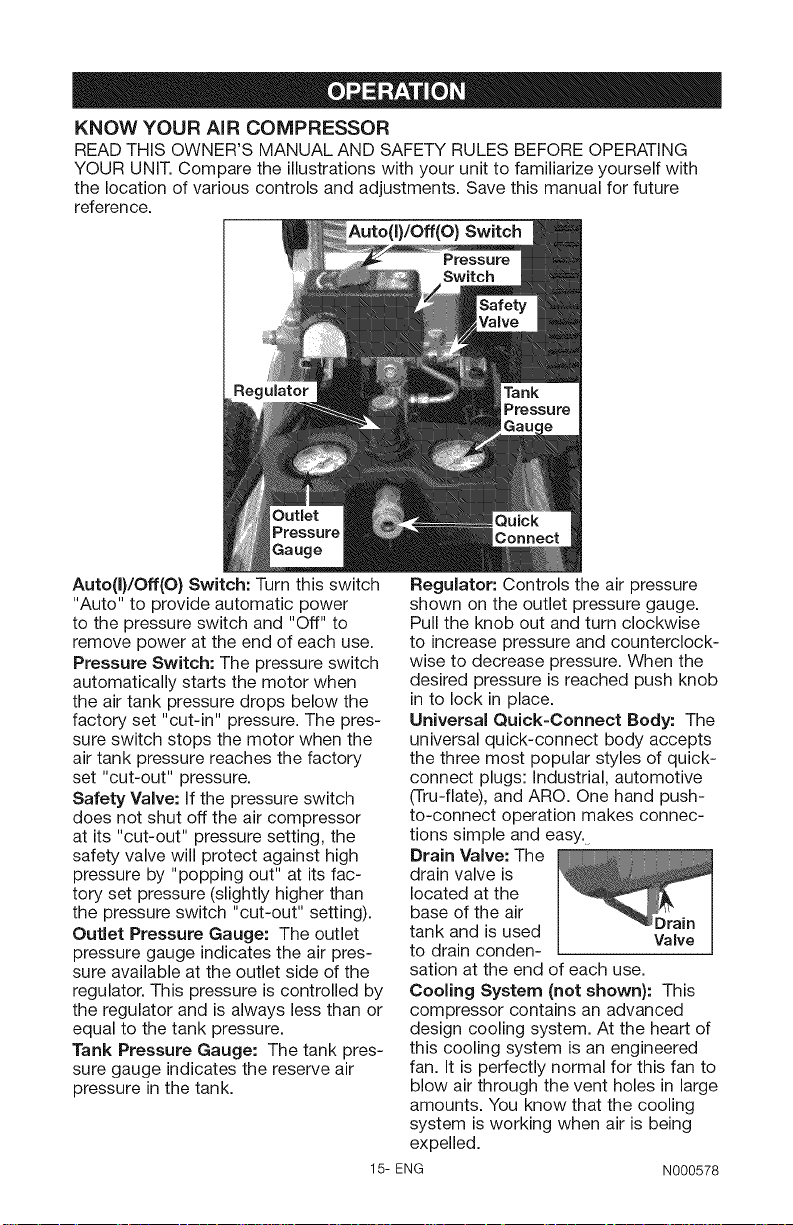
KNOW YOUR AIR COMPRESSOR
READ THIS OWNER'S MANUAL AND SAFETY RULES BEFORE OPERATING
YOUR UNIT. Compare the illustrations with your unit to familiarize yourself with
the location of various controls and adjustments. Save this manual for future
reference.
Auto(I)/Off(O) Switch
Regulator
Auto(I)/Off(O) Switch: Turn this switch
"Auto" to provide automatic power
to the pressure switch and "Off" to
remove power at the end of each use.
Pressure Switch: The pressure switch
automatically starts the motor when
the air tank pressure drops below the
factory set "cut-in" pressure. The pres-
sure switch stops the motor when the
air tank pressure reaches the factory
set "cut-out" pressure.
Safety Valve: If the pressure switch
does not shut off the air compressor
at its "cut-out" pressure setting, the
safety valve will protect against high
pressure by "popping out" at its fac-
tory set pressure (slightly higher than
the pressure switch "cut-out" setting).
Outlet Pressure Gauge: The outlet
pressure gauge indicates the air pres-
sure available at the outlet side of the
regulator. This pressure is controlled by
the regulator and is always less than or
equal to the tank pressure.
Tank Pressure Gauge: The tank pres-
sure gauge indicates the reserve air
pressure in the tank.
Regulator: Controls the air pressure
shown on the outlet pressure gauge.
Pull the knob out and turn clockwise
to increase pressure and counterclock-
wise to decrease pressure. When the
desired pressure is reached push knob
in to lock in place.
Universal Quick-Connect Body: The
universal quick-connect body accepts
the three most popular styles of quick-
connect plugs: Industrial, automotive
(Tru-flate), and ARC. One hand push-
to-connect operation makes connec-
tions simple and easy.
Drain Valve: The
drain valve is
located at the
base of the air
tank and is used
to drain conden-
sation at the end of each use.
Cooling System (not shown): This
compressor contains an advanced
design cooling system. At the heart of
this cooling system is an engineered
fan. It is perfectly normal for this fan to
blow air through the vent holes in large
amounts. You know that the cooling
system is working when air is being
expelled.
15- ENG
Valve
N000578
Air Compressor Pump (not shown):
Compresses air into the air tank.
Working air is not available until the
compressor has raised the air tank
pressure above that required at the air
outlet.
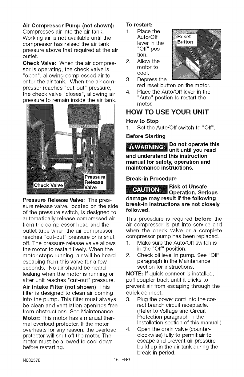
Check Valve: When the air compres-
sor is operating, the check valve is
"open", allowing compressed air to
enter the air tank. When the air com-
pressor reaches "cut-out" pressure,
the check valve "closes", allowing air
pressure to remain inside the air tank.
To restart:
1. Place the
Auto/Off
lever in the
"Off" pos-
tion.
2. Allow the
motor to
cool.
3. Depress the
red reset button on the motor.
4. Place the Auto/Off lever in the
"Auto" postion to restart the
motor.
HOW TO USE YOUR UNIT
How to Stop
1. Set the Auto/Off switch to "Off".
Before Starting
Pressure Release Valve: The pres-
sure release valve, located on the side
of the pressure switch, is designed to
automatically release compressed air
from the compressor head and the
outlet tube when the air compressor
reaches "cut-out" pressure or is shut
off. The pressure release valve allows
the motor to restart freely. When the
motor stops running, air will be heard
escaping from this valve for a few
seconds. No air should be heard
leaking when the motor is running or
after unit reaches "cut-out" pressure.
Air intake Filter (not shown) This
filter is designed to clean air coming
into the pump. This filter must always
be clean and ventilation openings free
from obstructions. See Maintenance.
Motor: This motor has a manual ther-
mal overload protector. If the motor
overheats for any reason, the overload
protector will shut off the motor. The
motor must be allowed to cool down
before restarting.
N000578
E__ o not operate this
unit until you read
and understand this instruction
manual for safety, operation and
maintenance instructions.
Break=in Procedure
Risk of Unsafe
Operation. Serious
damage may result if the following
break=in instructions are not closely
followed.
This procedure is required before the
air compressor is put into service and
when the check valve or a complete
compressor pump has been replaced.
1. Make sure the Auto/Off switch is
in the "Off" position.
2. Check oil level in pump. See "Oil"
paragraph in the Maintenance
section for instructions.
NOTE: If quick connect is installed,
pull coupler back until it clicks to
prevent air from escaping through the
quick connect.
3. Plug the power cord into the cor-
rect branch circuit receptacle.
(Refer to Voltage and Circuit
Protection paragraph in the
Installation section of this manual.)
4. Open the drain valve (counter-
clockwise) fully to permit air to
escape and prevent air pressure
build up in the air tank during the
break-in period.
16- ENG
5. MovetheAuto/Offswitchto"Auto"
position.Thecompressorwillstart.
6. Runthecompressorfor20min-
utes.Makesurethedrainvalve
isopenandthereisminimalair
pressurebuild-upintank.
7. After20minutes,closethedrain
valvebyturningclockwise.Theair
receiverwillfillto"cut-out"pres-
sureandthemotorwillstop.
Thecompressorisnowreadyforuse.
BeforeEachStart=Up
1. SettheAuto/Offswitchto"Off".
2. Pullregulatorknobout,turn
counterclockwiseuntilitstops.
Pushknobintolockinplace.
3. Attachhoseandaccessories.
NOTE:Thehoseoraccessorywill
requireaquickconnectplugifthe
airoutletisequipped with a quick
connect socket.
_Risk of unsafe
__ operation. Firmly
grasp air hose in hand when
installing or disconnecting to
prevent hose whip.
_Risk of unsafe
__ operation. Do not
use damaged or worn accessories.
Risk of unsafe
Compressed air from the unit may
contain water condensation and
oil mist. Do not spray unfiltered air
at an item that could be damaged
by moisture. Some air tools and
accessories may require filtered
air. Read the instructions for the air
tools and accessories.
Bow to Start
1. Set the Auto/Off switch to "Auto"
and allow tank pressure to build.
Motor will stop when tank pressure
reaches "cut-out" pressure.
2. Pull the regulator knob out and
turn clockwise to increase pres-
sure. When the desired pressure
is reached push knob in to lock in
place.
_lf any unusual
__ noise or vibration
is noticed, stop the compressor
immediately and have it checked by
a trained service technician.
The compressor is ready for use.
operation.
Risk of Bursting.
Too much air
pressure causes a hazardous risk of
bursting. Check the manufacturer's
maximum pressure rating for air
tools and accessories. The regulator
outlet pressure must never exceed
the maximum pressure rating.
17- ENG N000578
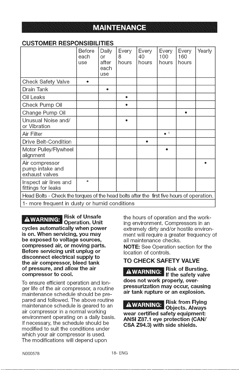
CUSTOMER RESPONSiBiLiTiES
Before iDaily Every Every Every Every Yearly
each ior 8 40 100 160
use after hours ihours hours hours
each
use
Check Safety Valve •
Drain Tank
Oil Leaks
Check Pump Oil
Change Pump Oil
Unusual Noise and/
or Vibration
Air Filter o 1
Drive Belt-Condition
Motor Pulley/Flywheel
alignment
Air compressor
pump intake and
exhaust valves
Inspect air lines and *
fittings for leaks
Head Bolts - Check thetorques of the head bolts after the first five hours of operation.
1- more frequent in dusty or humid conditions
_Risk of Unsafe
__ Operation. Unit
cycles automatically when power
is on. When servicing, you may
be exposed to voltage sources,
compressed air, or moving parts.
Before servicing unit unplug or
disconnect electrical supply to
the air compressor, bleed tank
of pressure, and allow the air
compressor to cool.
To ensure efficient operation and lon-
ger life of the air compressor, a routine
maintenance schedule should be pre-
pared and followed. The above routine
maintenance schedule is geared to an
air compressor in a normal working
environment operating on a daily basis.
If necessary, the schedule should be
modified to suit the conditions under
which your air compressor is used.
The modifications will depend upon
N000578 18-ENG
the hours of operation and the work-
ing environment. Compressors in an
extremely dirty and/or hostile environ-
ment will require a greater frequency of
all maintenance checks.
NOTE: See Operation section for the
location of controls.
TO CHECK SAFETY VALVE
E__ Risk of Bursting.
does not work properly, over=
pressurization may occur, causing
air tank rupture or an explosion.
E__ Risk from Flying
__ Objects. Always
wear certified safety equipment:
ANSi Z87.1 eye protection (CAN/
CSA Z94.3) with side shields.
If the safety valve
 Loading...