

Craftsman 919167812 Owner’s Manual
Owner's Manual
Oil Lube Two Stage
Air Compressor
AiR COMPRESSOR
= Safety Guidelines
= Assembly
= Operation
= Maintenance
= Troubleshooting
= Repair Parts
CAUTION: Read the Safety Guidelines
and All Instructions Carefully Before
Operating.
Sears, Roebuck and Co., Hoffman Estates, IL 60179 U.S.A.
Visit our Craftsman website: www.sears.com/craftsman
N004035 Rev.0 4/14/08

WARRANTY ................................................ 2
SPECiFiCATiON CHART ...................................... 2
SAFETY GUiDELiNES ...................................... 3-8
GLOSSARY ................................................ 9
DUTY CYCLE ............................................... 9
ACCESSORIES ............................................. 9
ASSEMBLY ............................................... 10
INSTALLATION ......................................... 10-12
OPERATION ............................................ 13-15
MAINTENANCE ......................................... 16-19
SERVICE AND ADJUSTMENTS ............................ 19-20
STORAGE ................................................ 21
TROUBLESHOOTING GUIDE .............................. 21-24
REPAIR PARTS ......................................... 26-29
ESPANOL .............................................. 30-55
REPAIR PROTECTION AGREEMENTS ......................... 56
HOW TO ORDER REPAIR PARTS ...................... back cover
ONE YEAR FULL WARRANTY
if this product fails clue to a defect in material or workmanship within one year
from the date of purchase, Sears will at its option repair or replace it free of
charge. Contact Sears at 1-800-4-MY-HOME ®to arrange for repair, or return it
to the place of purchase for replacement.
If this product is used for commercial or rental purposes, this warranty applies
for only ninety days from the date of purchase.
This warranty gives you specific legal rights and you may have other rights
which vary from state to state.
Sears, Roebuck and Co., Dept. 817WA, Hoffman Estates, IL 60179
Model No.
Running Horsepower
Voltage-Single Phase
Minimum Branch Circuit Requirement
Fuse Type
Air Tank Capacity, Gallons
Approximate Cut-in Pressure
Approximate Cut-out Pressure
SCFM @ 100 psig
SCFM @ 175 psig
919.167812
*5.4
240V
30 amps
Time Delay
80 ASME, Vertical
140 psig
175 psig
"13.3
"12.8
* Tested per ISO 1217
Refer to Glossary for abbreviations.
N004035 2-ENG
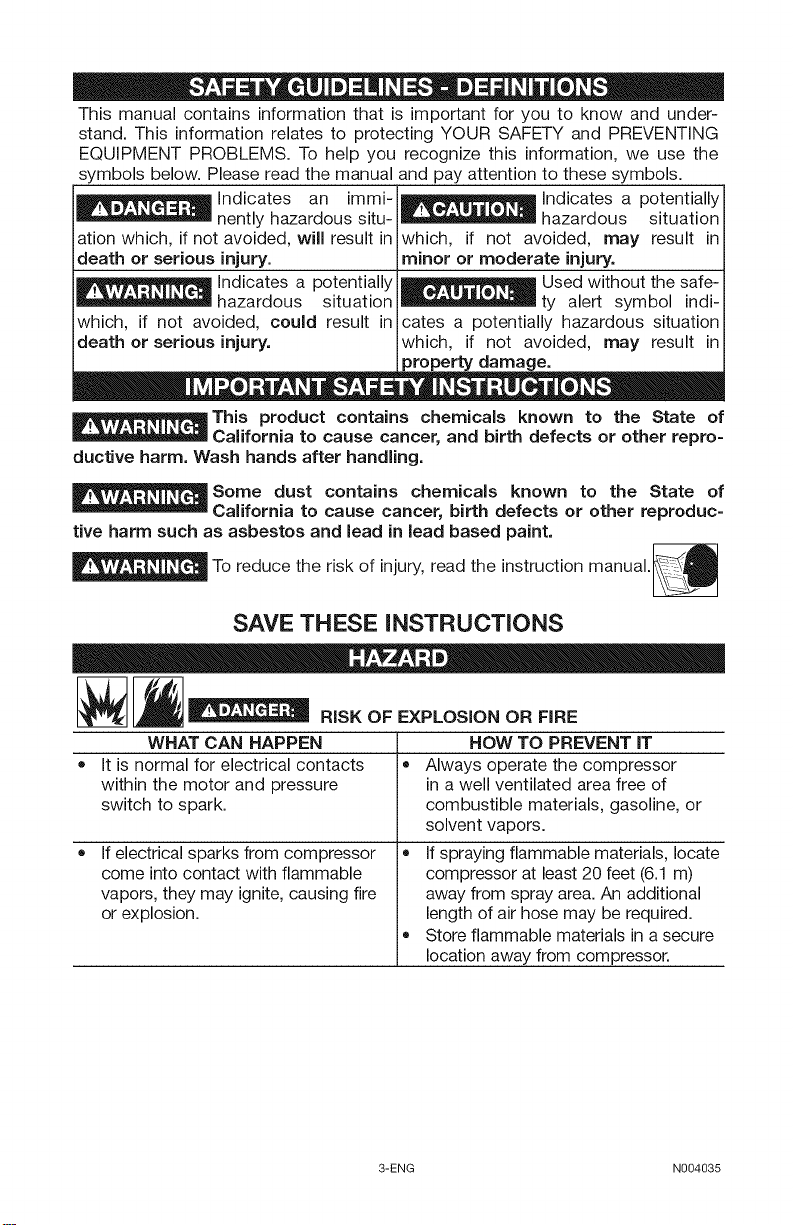
This manual contains information that is important for you to know and under-
stand. This information relates to protecting YOUR SAFETY and PREVENTING
EQUIPMENT PROBLEMS. To help you recognize this information, we use the
symbols below. Please read the manual and pay attention to these symbols.
i1_ Indicates an immi- _ Indicates a potentially
i = o -
nentlyhazardoussitu- = " " "
hazardous situation
iation which, if not avoided, will result in which, if not avoided, may result in
ideath or serious injury.
i1_ Indicates a potentially
hazardous situation
iwhich, if not avoided, could result in
death or serious injury,
minor or moderate injury,
Used without the safe-
ty alert symbol indi-
cates a potentially hazardous situation
which, if not avoided, may result in
property damage.
"0 = , ", = O
This product contains chemicals known to the State of
California to cause cancer, and birth defects or other repro-
ductive harm. Wash hands after handling.
Some dust contains chemicals known to the State of
California to cause cancer, birth defects or other reproduc-
tive harm such as asbestos and lead in lead based paint.
_To reduce the risk of injury, read the instruction manual._
SAVE THESE INSTRUCTIONS
' °- " RISK OF EXPLOSION OR FIRE
WHAT CAN HAPPEN
• It is normal for electrical contacts
within the motor and pressure
switch to spark.
• •
Ifelectrical sparks from compressor
come into contact with flammable
vapors, they may ignite, causing fire
or explosion.
3-ENG N004035
HOW TO PREVENT IT
Always operate the compressor
in a well ventilated area free of
combustible materials, gasoline, or
solvent vapors.
Ifspraying flammable materials, locate
compressor at least 20 feet (6.1 m)
away from spray area. An additional
length of air hose may be required.
Store flammable materials in asecure
location away from compressor.
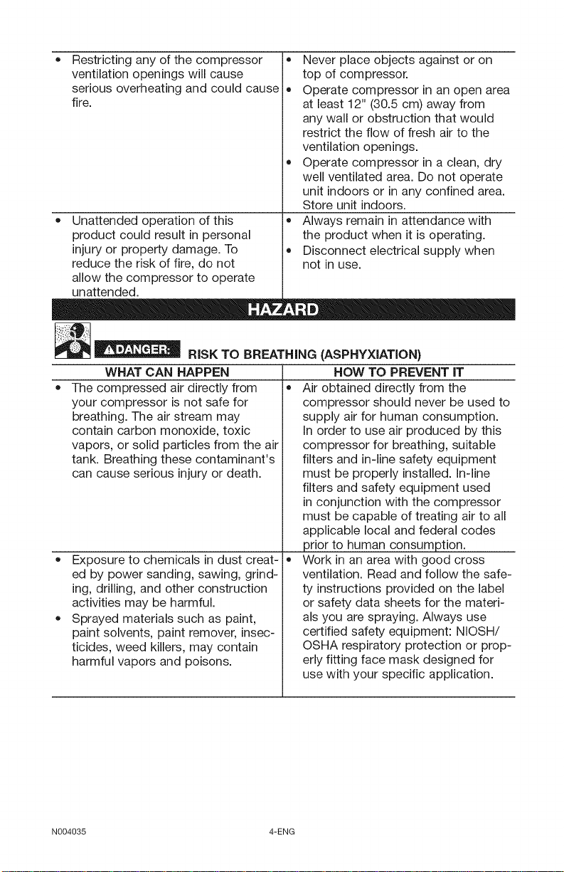
Restricting any of the compressor
ventilation openings will cause
serious overheating and could cause
fire.
Never place objects against or on
top of compressor.
Operate compressor in an open area
at least 12" (30.5 cm) away from
any wall or obstruction that would
restrict the flow of fresh air to the
ventilation openings.
Operate compressor in a clean, dry
well ventilated area. Do not operate
unit indoors or in any confined area.
Store unit indoors.
• Unattended operation of this
product could result in personal
injury or property damage. To
reduce the risk of fire, do not
Always remain in attendance with
the product when it is operating.
Disconnect electrical supply when
not in use.
allow the compressor to operate
unattended.
_"ID
__ RISK TO BREATHING (ASPHYXIATION)
WHAT CAN HAPPEN
The compressed air directly from
your compressor is not safe for
breathing. The air stream may
contain carbon monoxide, toxic
vapors, or solid particles from the air
tank. Breathing these contaminant's
can cause serious injury or death.
HOW TO PREVENT IT
Air obtained directly from the
compressor should never be used to
supply air for human consumption.
In order to use air produced by this
compressor for breathing, suitable
filters and in-line safety equipment
must be properly installed. In-line
filters and safety equipment used
in conjunction with the compressor
must be capable of treating air to all
applicable local and federal codes
prior to human consumption.
Exposure to chemicals in dust creat-
ed by power sanding, sawing, grind-
ing, drilling, and other construction
activities may be harmful.
Sprayed materials such as paint,
paint solvents, paint remover, insec-
ticides, weed killers, may contain
harmful vapors and poisons.
Work in an area with good cross
ventilation. Read and follow the safe-
ty instructions provided on the label
or safety data sheets for the materi-
als you are spraying. Always use
certified safety equipment: NIOSH/
OSHA respiratory protection or prop-
erly fitting face mask designed for
use with your specific application.
N004035 4-ENG
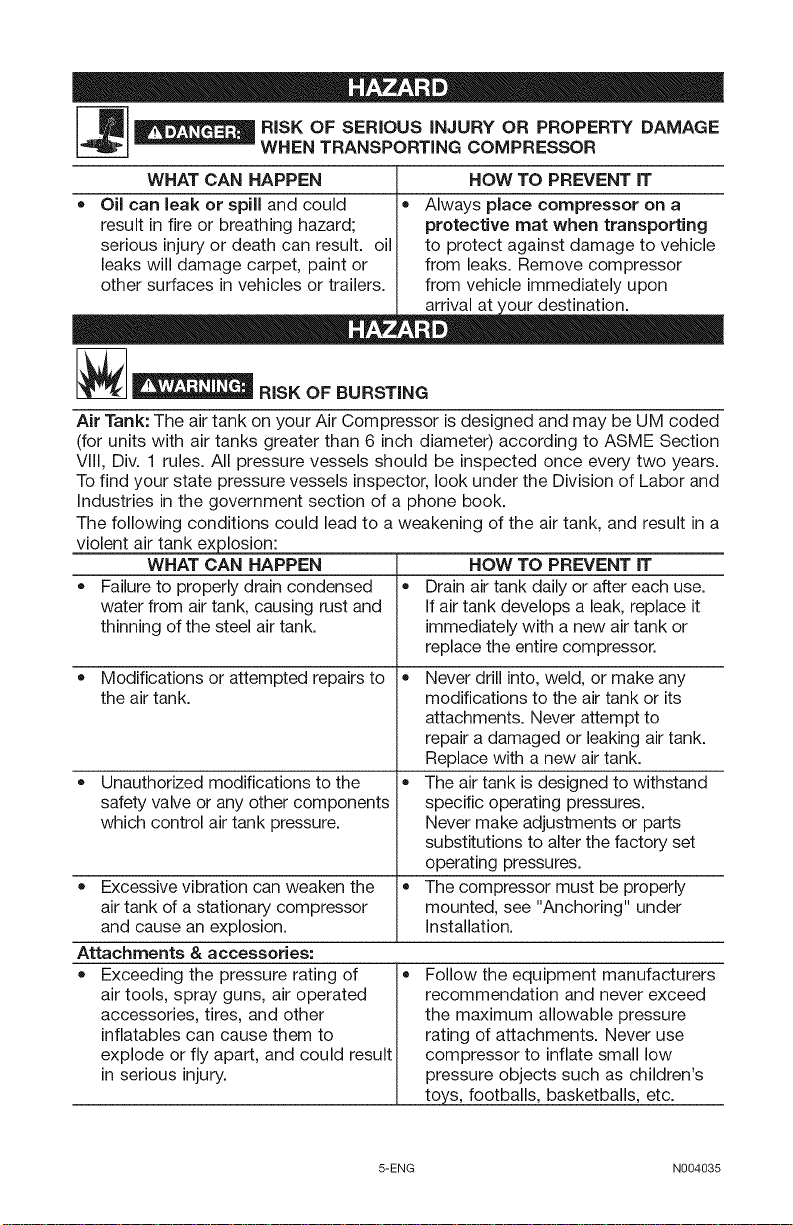
__ ISK OF SERIOUS iNJURY OR PROPERTY DAMAGE
WHAT CAN HAPPEN
Oil can leak or spill and could •
result in fire or breathing hazard;
serious injury or death can result, oil
leaks will damage carpet, paint or
other surfaces in vehicles or trailers.
__ RISK OF BURSTING
WHEN TRANSPORTING COMPRESSOR
HOW TO PREVENT IT
Always place compressor on a
protective mat when transporting
to protect against damage to vehicle
from leaks. Remove compressor
from vehicle immediately upon
Air Tank: The air tank on your Air Compressor is designed and may be UM coded
(for units with air tanks greater than 6 inch diameter) according to ASME Section
Viii, Div. 1 rules. All pressure vessels should be inspected once every two years.
Tofind your state pressure vessels inspector, look under the Division of Labor and
industries in the government section of a phone book.
The following conditions could lead to a weakening of the air tank, and result in a
violent air tank explosion:
WHAT CAN HAPPEN HOW TO PREVENT iT
Failure to properly drain condensed • Drain air tank daily or after each use.
water from air tank, causing rust and If air tank develops a leak, replace it
thinning of the steel air tank. immediately with a new air tank or
replace the entire compressor.
Modifications or attempted repairs to • Never drill into, weld, or make any
the air tank. modifications to the air tank or its
attachments. Never attempt to
repair a damaged or leaking air tank.
Replace with a new air tank.
Unauthorized modifications to the • The air tank is designed to withstand
safety valve or any other components specific operating pressures.
which control air tank pressure. Never make adjustments or parts
substitutions to alter the factory set
operating pressures.
Excessive vibration can weaken the • The compressor must be properly
air tank of a stationary compressor mounted, see "Anchoring" under
and cause an explosion, installation.
Attachments & accessories:
Exceeding the pressure rating of
air tools, spray guns, air operated
accessories, tires, and other
inflatables can cause them to
explode or fly apart, and could result
in serious injury.
Follow the equipment manufacturers
recommendation and never exceed
the maximum allowable pressure
rating of attachments. Never use
compressor to inflate small low
pressure objects such as children's
toys, footballs, basketballs, etc.
5-ENG N004035
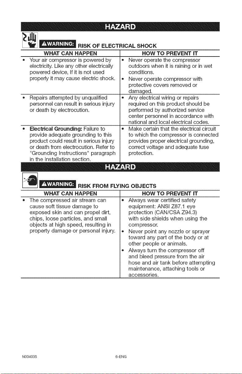
[__ RISK OF ELECTRICAL SHOCK
WHAT CAN HAPPEN
Your air compressor is powered by
electricity. Like any other electrically
powered device, If it is not used
properly it may cause electric shock.
HOW TO PREVENT iT
Never operate the compressor
outdoors when it is raining or in wet
conditions.
Never operate compressor with
protective covers removed or
damaged.
• Repairs attempted by unqualified
personnel can result in serious injury
or death by electrocution.
Any electrical wiring or repairs
required on this product should be
performed by authorized service
center personnel in accordance with
national and local electrical codes.
Electrical Grounding: Failure to
provide adequate grounding to this
product could result in serious injury
or death from electrocution. Refer to
"Grounding Instructions" paragraph
Make certain that the electrical circuit
to which the compressor is connected
provides proper electrical grounding,
correct voltage and adequate fuse
protection.
in the Installation section.
__ RiSK FROM FLYING OBJECTS
WHAT CAN HAPPEN
The compressed air stream can
cause soft tissue damage to
exposed skin and can propel dirt,
chips, loose particles, and small
objects at high speed, resulting in
property damage or personal injury.
HOW TO PREVENT iT
Always wear certified safety
equipment: ANSI Z87.1 eye
protection (CAN/CSA Z94.3)
with side shields when using the
com pressor.
Never point any nozzle or sprayer
toward any part of the body or at
other people or animals.
Always turn the compressor off
and bleed pressure from the air
hose and air tank before attempting
maintenance, attaching tools or
accessories.
N004035 6-ENG
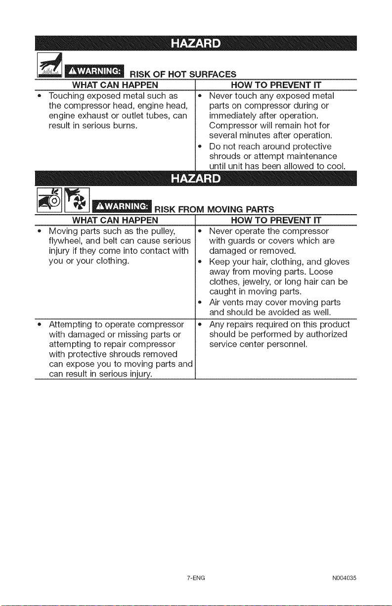
__ RiSK OF HOT SURFACES
WHAT CAN HAPPEN
Touching exposed metal such as
the compressor head, engine head,
engine exhaust or outlet tubes, can
result in serious burns.
Never touch any exposed metal
parts on compressor during or
immediately after operation.
Compressor will remain hot for
several minutes after operation.
Do not reach around protective
shrouds or attempt maintenance
until unit has been allowed to cool.
_ m D
HOW TO PREVENT IT
E==I °,sKF°o.
WHAT CAN HAPPEN
• Moving parts such as the pulley,
flywheel, and belt can cause serious
injury if they come into contact with
you or your clothing.
Attempting to operate compressor
with damaged or missing parts or
attempting to repair compressor
with protective shrouds removed
can expose you to moving parts and
can result in serious injury.
MOVING PARTS
HOW TO PREVENT IT
Never operate the compressor
with guards or covers which are
damaged or removed.
Keep your hair, clothing, and gloves
away from moving parts. Loose
clothes, jewelry, or long hair can be
caught in moving parts.
o
Air vents may cover moving parts
and should be avoided as well.
o
Any repairs required on this product
should be performed by authorized
service center personnel.
7-ENG N004035
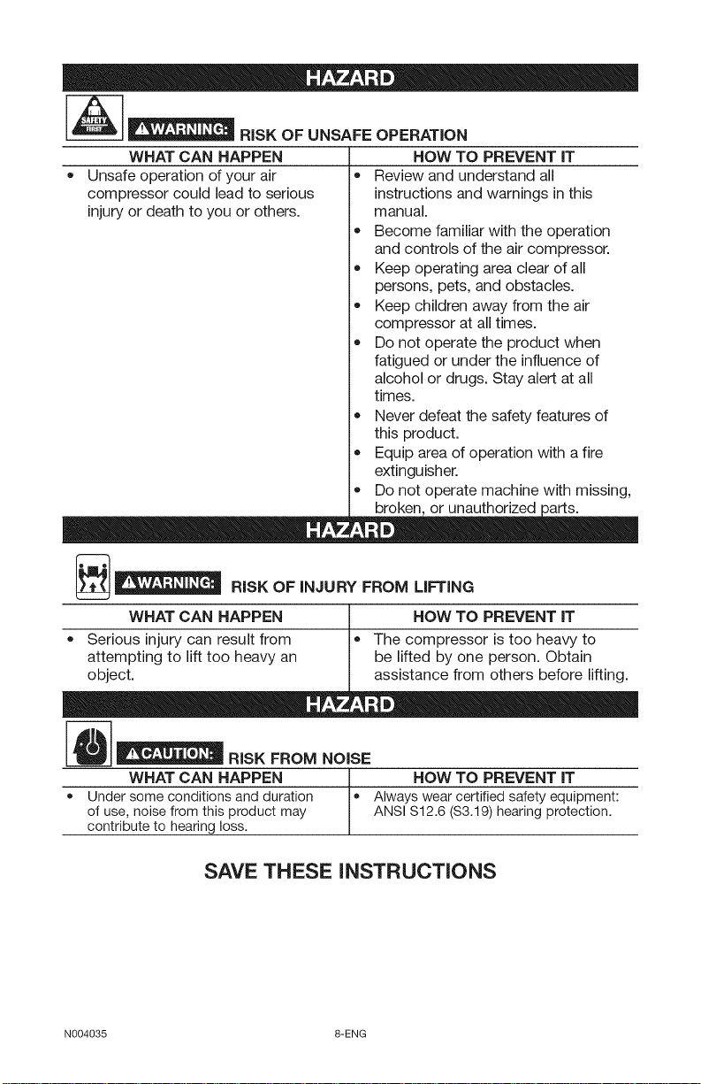
__ RISK OF UNSAFE OPERATION
WHAT CAN HAPPEN
• Unsafe operation of your air
compressor could lead to serious
injury or death to you or others.
• Review and understand all
HOW TO PREVENT IT
instructions and warnings in this
manual.
Become familiar with the operation
and controls of the air compressor.
Keep operating area clear of all
persons, pets, and obstacles.
Keep children away from the air
compressor at all times.
Do not operate the product when
fatigued or under the influence of
alcohol or drugs. Stay alert at all
times.
Never defeat the safety features of
this product.
Equip area of operation with a fire
extinguisher.
o
Do not operate machine with missing,
broken or unauthorized
[__ RISK OF INJURY FROM LIFTING
WHAT CAN HAPPEN
Serious injury can result from
attempting to lift too heavy an
object.
• The compressor is too heavy to
_ m D
HOW TO PREVENT iT
be lifted by one person. Obtain
assistance from others before lifting.
_ "" " RISK FROM NOISE
WHAT CAN HAPPEN HOW TO PREVENT IT
• Under someconditions and duration • Always wear certified safety equipment:
of use, noise fromthis product may ANSI$12.6 ($3.19)hearingprotection.
contribute to hearing loss.
SAVE THESE iNSTRUCTiONS
N004035 8-ENG
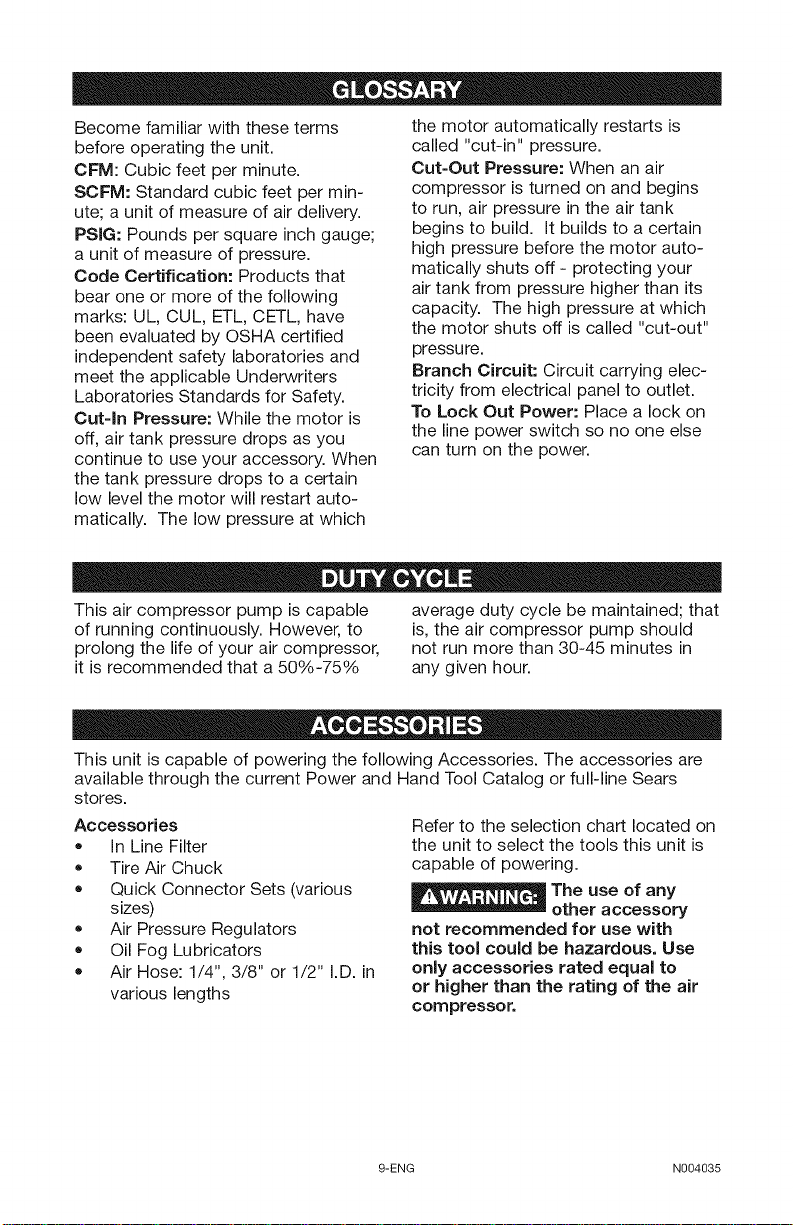
Become familiar with these terms
before operating the unit.
CFM: Cubic feet per minute.
SCFM: Standard cubic feet per min-
ute; a unit of measure of air delivery.
PSIG: Pounds per square inch gauge;
a unit of measure of pressure.
Code Certification: Products that
bear one or more of the following
marks: UL, CUL, ETL, CETL, have
been evaluated by OSHA certified
independent safety laboratories and
meet the applicable Underwriters
Laboratories Standards for Safety.
Cut-In Pressure: While the motor is
off, air tank pressure drops as you
continue to use your accessory. When
the motor automatically restarts is
called "cut-in" pressure.
Cut-Out Pressure: When an air
compressor is turned on and begins
to run, air pressure in the air tank
begins to build. It builds to a certain
high pressure before the motor auto-
matically shuts off - protecting your
air tank from pressure higher than its
capacity. The high pressure at which
the motor shuts off is called "cut-out"
pressure.
Branch Circuit: Circuit carrying elec-
tricity from electrical panel to outlet.
To Lock Out Power: Place a lock on
the line power switch so no one else
can turn on the power.
the tank pressure drops to a certain
low level the motor will restart auto-
matically. The low pressure at which
This air compressor pump is capable average duty cycle be maintained; that
of running continuously. However, to is, the air compressor pump should
prolong the life of your air compressor, not run more than 30-45 minutes in
it is recommended that a 50%-75% any given hour.
This unit is capable of powering the following Accessories. The accessories are
available through the current Power and Hand Tool Catalog or full-line Sears
stores.
Accessories
• In Line Filter
• Tire Air Chuck
• Quick Connector Sets (various
sizes)
• Air Pressure Regulators
• Oil Fog Lubricators
• Air Hose: 1/4", 3/8" or 1/2" I.D. in
various lengths
Refer to the selection chart located on
the unit to select the tools this unit is
capable of powering.
_The use of any
-- other accessory
not recommended for use with
this tool could be hazardous. Use
only accessories rated equal to
or higher than the rating of the air
compressor.
9-ENG N004035
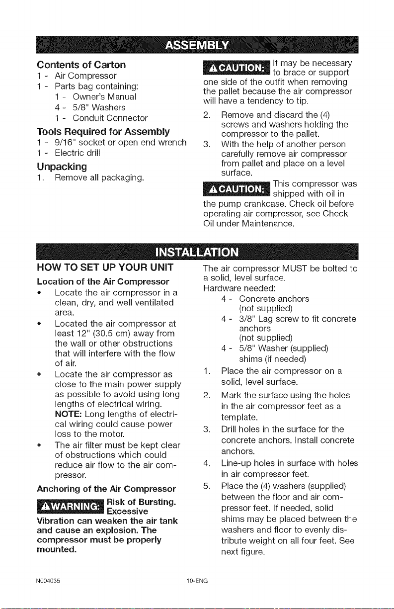
Contents of Carton
1 - Air Compressor
1 - Parts bag containing:
1 - Owner's Manual
4 - 5/8" Washers
1 - Conduit Connector
Tools Required for Assembly
1 - 9/16" socket or open end wrench
1 - Electric drill
Unpacking
1. Remove all packaging.
lt may be necessary
to brace or support
one side of the outfit when removing
the pallet because the air compressor
will have a tendency to tip.
2. Remove and discard the (4)
screws and washers holding the
compressor to the pallet.
3. With the help of another person
carefully remove air compressor
from pallet and place on a level
surface.
_This compressor was
__ shipped with oil in
the pump crankcase. Check oil before
operating air compressor, see Check
Oil under Maintenance.
HOW TO SET UP YOUR UNiT
Location of the Air Compressor
• Locate the air compressor in a
clean, dry, and well ventilated
area.
• Located the air compressor at
least 12" (30.5 cm) away from
the wall or other obstructions
that will interfere with the flow
of air.
• Locate the air compressor as
close to the main power supply
as possible to avoid using long
lengths of electrical wiring.
NOTE: Long lengths of electri-
cal wiring could cause power
loss to the motor.
• The air filter must be kept clear
of obstructions which could
reduce air flow to the air com-
pressor.
Anchoring of the Air Compressor
E__ Risk of Bursting.
__ Excessive
Vibration can weaken the air tank
and cause an explosion. The
compressor must be properly
mounted.
The air compressor MUST be bolted to
a solid, level surface.
Hardware needed:
4 - Concrete anchors
(not supplied)
4 - 3/8" Lag screw to fit concrete
anchors
(not supplied)
4 - 5/8" Washer (supplied)
shims (if needed)
1. Place the air compressor on a
solid, level surface.
2. Mark the surface using the holes
in the air compressor feet as a
template.
3. Drill holes in the surface for the
concrete anchors. Install concrete
anchors.
4. Line-up holes in surface with holes
in air compressor feet.
5. Place the (4) washers (supplied)
between the floor and air com-
pressor feet. If needed, solid
shims may be placed between the
washers and floor to evenly dis-
tribute weight on all four feet. See
next figure.
N004035 10-ENG
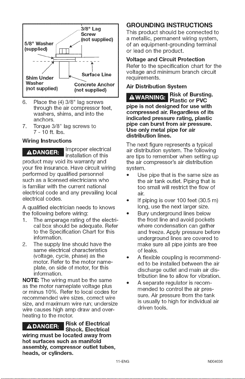
.......3/8" Lag
..................Screw
5/8" Washer ,................../(not supplied)
(supplied) i_" I
Sh,m___rface-- L,ne
Washer Concrete Anchor
(not supplied) (not supplied)
6. Place the (4)3/8" lag screws
through the air compressor feet,
washers, shims, and into the
anchors.
7. Torque 3/8" lag screws to
7-10 ft. Ibs.
Wiring instructions
_ Improper electrical
installation of this
product may void its warranty and
your fire insurance. Have circuit wiring
performed by qualified personnel
such as a licensed electricians who
is familiar with the current national
electrical code and any prevailing local
electrical codes.
A qualified electrician needs to knows
the following before wiring:
1. The amperage rating of the electri-
cal box should be adequate. Refer
to the Specification Chart for this
information.
2. The supply line should have the
same electrical characteristics
(voltage, cycle, phase) as the
motor. Refer to the motor name-
plate, on side of motor, for this
information.
NOTE: The wiring must be the same
as the motor nameplate voltage plus
or minus 10%. Refer to local codes for
recommended wire sizes, correct wire
size, and maximum wire run; undersize
wire causes high amp draw and over-
heating to the motor.
I__ Risk of Electrical
Shock. Electrical
wiring must be located away from
hot surfaces such as manifold
assembly, compressor outlet tubes,
heads, or cylinders.
GROUNDING INSTRUCTIONS
This product should be connected to
a metallic, permanent wiring system,
of an equipment-grounding terminal
or lead on the product.
Voltage and Circuit Protection
Refer to the specification chart for the
voltage and minimum branch circuit
requirements.
Air Distribution System
E__ isk of Bursting.
Plastic or PVC
pipe is not designed for use with
compressed air. Regardless of its
indicated pressure rating, plastic
pipe can burst from air pressure.
Use only metal pipe for air
distribution lines.
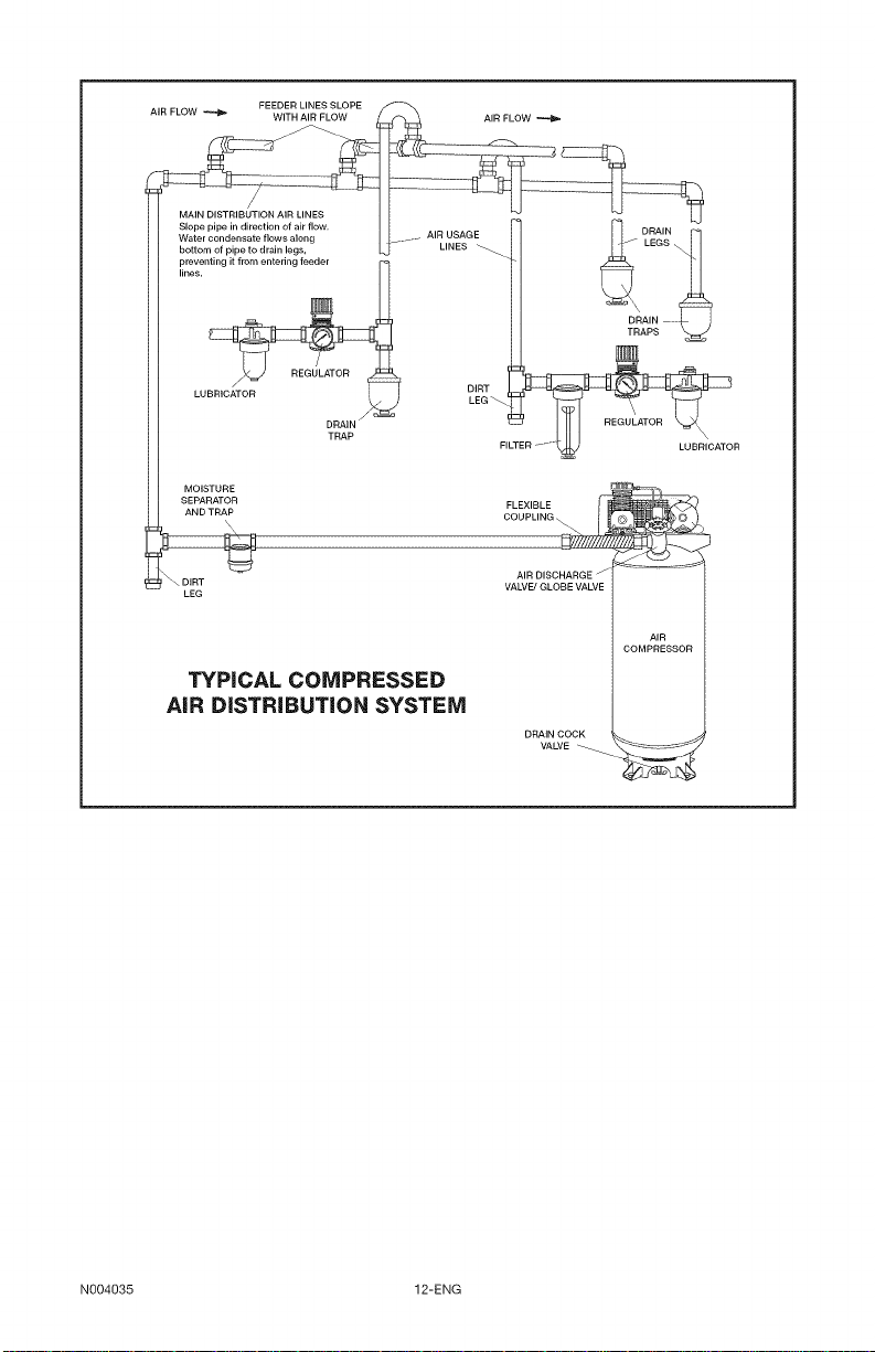
The next figure represents a typical
air distribution system. The following
are tips to remember when setting up
the air compressor's air distribution
system.
+ Use pipe that is the same size as
the air tank outlet. Piping that is
too small will restrict the flow of
air.
+ If piping is over 100 feet (30.5 m)
long, use the next larger size.
+ Bury underground lines below
the frost line and avoid pockets
where condensation can gather
and freeze. Apply pressure before
underground lines are covered to
make sure all pipe joints are free
of leaks.
+ A flexible coupling is recommend-
ed to be installed between the air
discharge outlet and main air dis-
tribution line to allow for vibration.
+ A separate regulator is recom-
mended to control the air pres-
sure. Air pressure from the tank
is usually to high for individual air
driven tools.
11-ENG N004035
AIR FLOW _ WITH AIR FLOW AIR FLOW
MOISTURE £1
SEPARATOR FLEXIBLE
t_AND TRAP t-ilICOUPLING __¢
\
u,., VALVE_GLOBEVALVE
LEG
FEEDER LINES SLOPE
DRAIN .......
AIR DISCHARGE - _=_
COMPRESSOR
DRAIN
LEGS
AIR
TYPICAL COMPRESSED
AiR DiSTRiBUTiON SYSTEM
DRAIN COCK
VALVE
LUBRICATOR
N004035 12-ENG
KNOW YOUR AiR COMPRESSOR
READ THIS OWNER'S MANUAL AND SAFETY RULES BEFORE OPERATING
YOUR UNIT. Compare the illustrations with your unit to familiarize yourself with
the location of various controls and adjustments. Save this manual for future ref-
erence.
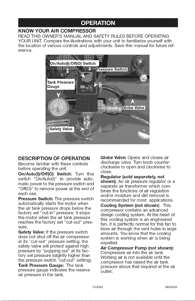
DESCRiPTiON OF OPERATION
Become familiar with these controls
before operating the unit.
On/Auto(I)/Off(O) Switch: Turn this
switch "On/Auto(i)" to provide auto-
matic power to the pressure switch and
"Off(O)" to remove power at the end of
each use.
Pressure Switch: The pressure switch
automatically starts the motor when
the air tank pressure drops below the
factory set "cut-in" pressure. It stops
the motor when the air tank pressure
reaches the factory set "cut-out" pres-
sure.
Safety Valve: If the pressure switch
does not shut off the air compressor
at its "cut-out" pressure setting, the
safety valve will protect against high
pressure by "popping out" at its fac-
tory set pressure (slightly higher than
the pressure switch "cut-out" setting).
Tank Pressure Gauge: The tank
pressure gauge indicates the reserve
air pressure in the tank.
Globe Valve: Opens and closes air
discharge valve. Turn knob counter-
clockwise to open and clockwise to
close.
Regulator (sold separately, not
shown): An air pressure regulator or a
separate air transformer which com-
bines the functions of air regulation
and/or moisture and dirt removal is
recommended for most applications.
Cooling System (not shown): This
compressor contains an advanced
design cooling system. At the heart of
this cooling system is an engineered
fan. It is perfectly normal for this fan to
blow air through the vent holes in large
amounts. You know that the cooling
system is working when air is being
expelled.
Air Compressor Pump (not shown):
Compresses air into the air tank.
Working air is not available until the
compressor has raised the air tank
pressure above that required at the air
outlet.
13-ENG N004035
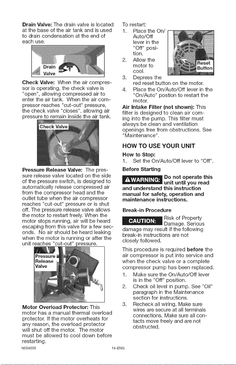
Drain Valve: The drain valve is located
at the base of the air tank and is used
to drain condensation at the end of
each use.
Drain
Valve
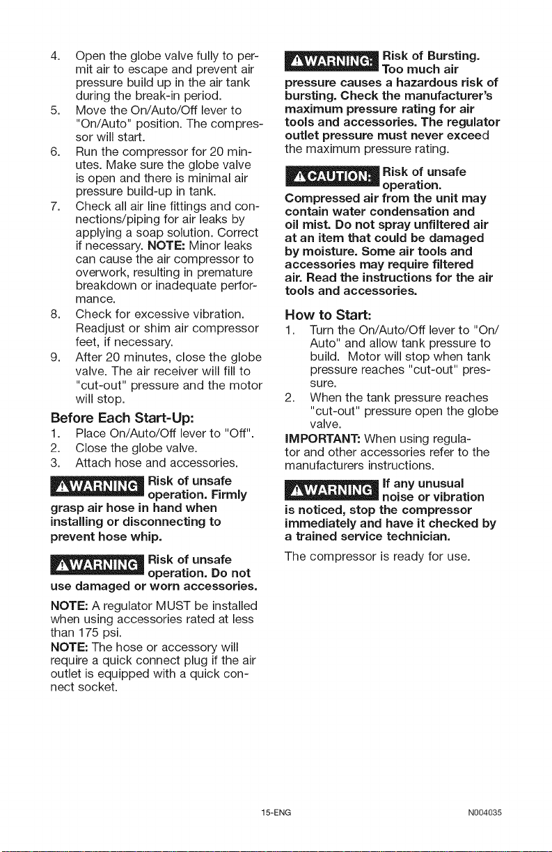
Check Valve: When the air compres-
sor is operating, the check valve is
"open", allowing compressed air to
enter the air tank. When the air com-
pressor reaches "cut-out" pressure,
the check valve "closes", allowing air
pressure to remain inside the air tank.
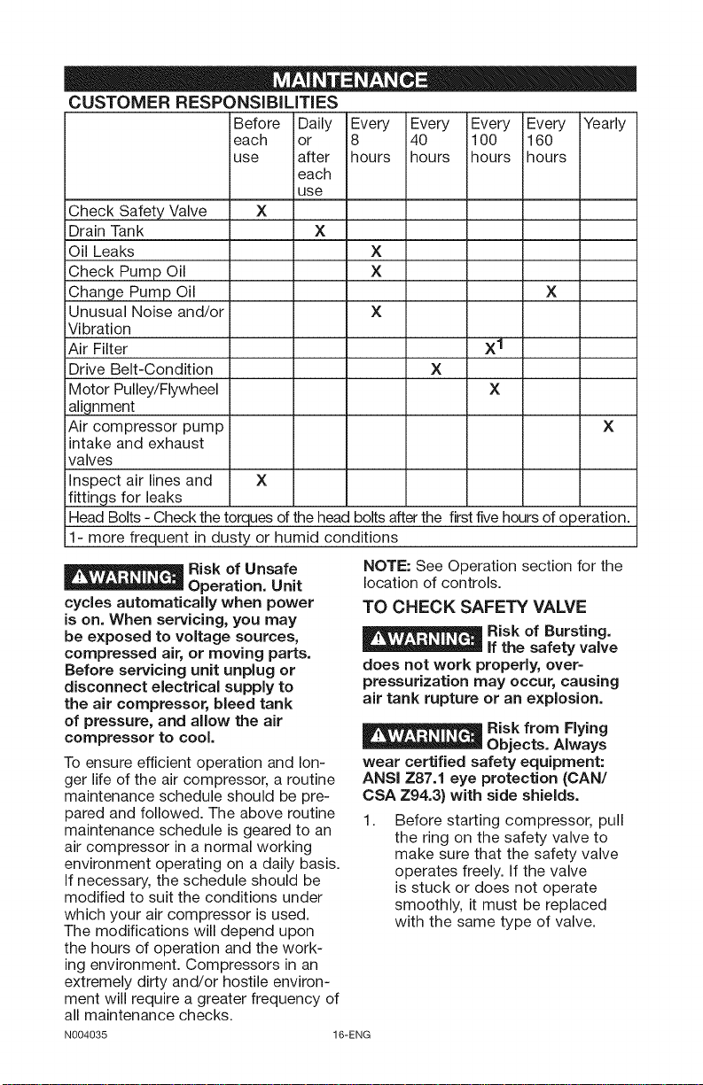
Pressure Release Valve: The pres-
sure release valve located on the side
of the pressure switch, is designed to
automatically release compressed air
from the compressor head and the
outlet tube when the air compressor
reaches "cut-out" pressure or is shut
off. The pressure release valve allows
the motor to restart freely. When the
motor stops running, air will be heard
escaping from this valve for a few sec-
onds. No air should be heard leaking
when the motor is running or after the
unit reaches "cut-out" 3ressure.
Motor Overload Protector: This
motor has a manual thermal overload
protector. If the motor overheats for
any reason, the overload protector
will shut off the motor. The motor
must be allowed to cool down before
restarting.
N004035 14-ENG
To restart:
1. Place the On/
Auto/Off
lever in the
"Off" posi-
tion.
2. Allow the
motor to
cool.
3. Depress the
red reset button on the motor.
4. Place the On/Auto/Off lever in the
"On/Auto" postion to restart the
motor.
Air intake Filter (not shown): This
filter is designed to clean air com-
ing into the pump. This filter must
always be clean and ventilation
openings free from obstructions. See
"Maintenance".
HOW TO USE YOUR UNiT
How to Stop:
1. Set the On/Auto/Off lever to "Off".
Before Starting
Do not operate this
unit until you read
and understand this instruction
manual for safety, operation and
maintenance instructions.
Break-in Procedure
Risk of Property
Damage. Serious
damage may result if the following
break-in instructions are not
closely followed.
This procedure is required before the
air compressor is put into service and
when the check valve or a complete
compressor pump has been replaced.
1. Make sure the On/Auto/Off lever
is in the "Off" position.
2. Check oil level in pump. See "Oil"
paragraph in the Maintenance
section for instructions.
3. Recheck all wiring. Make sure
wires are secure at all terminals
connections. Make sure all con-
tacts move freely and are not
obstructed.
4. Opentheglobevalvefullytoper-
mitairtoescapeandpreventair
pressurebuildupintheairtank
duringthebreak-inperiod.
5. MovetheOn/Auto/Offleverto
"On/Auto"position.Thecompres-
sorwillstart.
6. Runthecompressorfor20min-
utes.Makesuretheglobevalve
isopenandthereisminimalair
pressurebuild-upintank.
7. Checkallairlinefittingsandcon-
nections/pipingforairleaksby
applyingasoapsolution.Correct
ifnecessary.NOTE:Minorleaks
cancausetheaircompressorto
overwork,resultinginpremature
breakdownorinadequateperfor-
mance.
8. Checkforexcessivevibration.
Readjustorshimaircompressor
feet,ifnecessary.
9. After20minutes,closetheglobe
valve.Theairreceiverwillfillto
"cut-out"pressureandthemotor
willstop.
BeforeEachStart-Up:
1. PlaceOn/Auto/Offleverto"Off".
2. Closetheglobevalve.
3. Attachhoseandaccessories.
Riskofunsafe
operation.Firmly
grasp air hose in hand when
installing or disconnecting to
prevent hose whip.
Risk of unsafe
use damaged or worn accessories.
NOTE: A regulator MUST be installed
when using accessories rated at less
than 175 psi.
NOTE: The hose or accessory will
require a quick connect plug if the air
outlet is equipped with a quick con-
nect socket.
operation. Do not
Risk of Bursting.
Too much air
pressure causes a hazardous risk of
bursting. Check the manufacturer's
maximum pressure rating for air
tools and accessories. The regulator
outlet pressure must never exceed
the maximum pressure rating.
_Risk of unsafe
-- operation.
Compressed air from the unit may
contain water condensation and
oil mist. Do not spray unfiltered air
at an item that could be damaged
by moisture. Some air tools and
accessories may require filtered
air. Read the instructions for the air
tools and accessories.
How to Start:
1. Turn the On/Auto/Off lever to "On/
Auto" and allow tank pressure to
build. Motor will stop when tank
pressure reaches "cut-out" pres-
sure.
2. When the tank pressure reaches
"cut-out" pressure open the globe
valve.
IMPORTANT: When using regula-
tor and other accessories refer to the
manufacturers instructions.
_lf any unusual
__ noise or vibration
is noticed, stop the compressor
immediately and have it checked by
a trained service technician.
The compressor is ready for use.
15-ENG N004035
CUSTOMER RESPONSiBiLiTiES
Before Daily Every Every Every Every Yearly
each or 8 40 100 160
use after hours hours ihours hours
each
use
Check Safety Valve X
Drain Tank X
Oil Leaks X
Check Pump Oil X
Change Pump Oil X
Unusual Noise and/or X
Vibration
Air Filter X1
Drive Belt-Condition X
Motor Pulley/Flywheel X
alignment
Air compressor pump X
intake and exhaust
valves
Inspect air lines and X
fittings for leaks
Head Bolts - Check the torques of the head bolts after the first five hours of operation.
il- more frequent in dusty or humid conditions
_Risk of Unsafe
__ Operation. Unit
cycles automatically when power
is on. When servicing, you may
be exposed to voltage sources,
compressed air, or moving parts.
Before servicing unit unplug or
disconnect electrical supply to
the air compressor, bleed tank
of pressure, and allow the air
compressor to cool.
To ensure efficient operation and lon-
ger life of the air compressor, a routine
maintenance schedule should be pre-
pared and followed. The above routine
maintenance schedule is geared to an
air compressor in a normal working
environment operating on a daily basis.
If necessary, the schedule should be
modified to suit the conditions under
which your air compressor is used.
The modifications will depend upon
the hours of operation and the work-
ing environment. Compressors in an
extremely dirty and/or hostile environ-
ment will require a greater frequency of
all maintenance checks.
N004035
NOTE: See Operation section for the
location of controls.
TO CHECK SAFETY VALVE
_Risk of Bursting.
__ if the safety valve
does not work properly, over=
pressurization may occur, causing
air tank rupture or an explosion.
Risk from Flying
Objects. Always
wear certified safety equipment:
ANSI Z87.1 eye protection (CAN/
CSA Z94.3} with side shields.
1.
Before starting compressor, pull
the ring on the safety valve to
make sure that the safety valve
operates freely. If the valve
is stuck or does not operate
smoothly, it must be replaced
with the same type of valve.
16-ENG
TO DRAIN TANK
Risk of Unsafe
Operation. Risk
from noise. Air tanks contain high
pressure air. Keep face and other
body parts away from outlet of
drain. Use ANSI Z87.1 eye protection
(CAN/CSA Z94.3) when draining as
debris can be kicked up into face.
Use ear protection (ANSi S12.6
($3.19) hearing protection) as air flow
noise is loud when draining.
NOTE: Operation of the air compres-
sor will cause condensation to build up
in the air tank. Always drain tank on a
washable surface or in a suitable con-
tainer to prevent damaging or staining
surfaces.
1. Set the On/Auto/Off lever to "Off".
2. Close the globe valve.
3. Remove the air tool or accessory.
4. Open the globe valve and allow
the air to slowly bleed from the air
tank until tank pressure is approxi-
mately 20 psi.
5. Close the globe valve.
6. Drain water from air tank by open-
ing drain valve on bottom of tank.
_Risk of Bursting.
__ Water will condense
in the air tank. if not drained, water
will corrode and weaken the air tank
causing a risk of air tank rupture.
_Risk of Property
__ Damage. Drain water
from air tank may contain oil and rust
which can cause stains.
7. After the water has been drained,
close the drain valve. The air com-
pressor can now be stored.
NOTE: If drain valve is plugged,
release all air pressure. The valve can
then be removed, cleaned, then rein-
stalled.
OIL
Use air compressor
oil only. Multi-weight
automotive engine oils like 10W30
should not be use in air compressors.
They leave carbon deposits on
critical components, thus reducing
performance and compressor life.
NOTE: Use 30W compressor oil or a
heavy duty SAE 30W, non-detergent,
SF grade or better oil DO NOT use
multi-weight automotive engine oils,
they will reduce compressor life. Under
extreme winter condition use SAE-10
weight oil.
NOTE: Crankcase oil capacity is
approximately 48 fluid ounces (1.4 L).
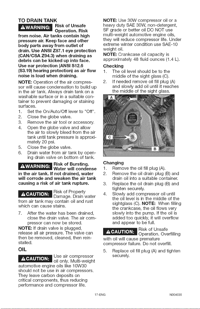
Checking
1. The oil level should be to the
middle of the sight glass (C).
2. If needed remove oil fill plug (A)
and slowly add oil until it reaches
the middle of the sight glass.
Changing
1. Remove the oil fill plug (A).
2. Remove the oil drain plug (B) and
drain oil into a suitable container.
3. Replace the oil drain plug (B) and
tighten securely.
4. Slowly add compressor oil until
the oil level is in the middle of the
sightglass (C). NOTE: When filling
the crankcase, the oil flows very
slowly into the pump. If the oil is
added too quickly, it will overflow
and appear to be full.
Risk of Unsafe
Operation. Overfilling
with oil will cause premature
compressor failure. Do not overfill.
5. Replace oil fill plug (A)and tighten
securely.
17-ENG N004035
 Loading...