

Craftsman 919165611 Owner’s Manual
Owner's Manual
JCRRFTSMRN1
Permanently Lubricated
Twin V
2-Stage
Stationary
AIR COMPRESSOR
Model No.
919.165611
• Safety Guidelines
• Assembly
• Operation
• Maintenance
• Troubleshooting
• Repair Parts
CAUTION: Read the Safety Guidelines
and All Instructions Carefully Before
Operating.
Sears, Roebuck and Co., Hoffman Estates, IL 60179 U.S.A.
Visit our Craftsman website: www.eears.com/craftsman
D29312 Rev. 1 6/12/03
hq;_:] ! :1EoJ_,_[_o] _hi _h I_-_
WARRANTY ............................................. 2
SPECIFICATION CHART .................................... 3
SAFETY GUIDELINES-DEFINITIONS .......................... 3
IMPORTANT SAFETY INSTRUCTIONS ....................... 3-8
GLOSSARY .............................................. 9
ACCESSORIES .......................................... 9
DUTY CYCLE ............................................ 9
ASSEMBLY ............................................. 1O
INSTALLATION ........................................ fO-12
OPERATION .......................................... f3- 15
MAINTENANCE ....................................... f6-17
SERVICE AND ADJUSTMENTS ............................. 18
STORAGE .............................................. 19
TROUBLESHOOTING GUIDE ............................ 20-22
REPAIR PARTS ....................................... 23-27
HOW TO ORDER REPAIR PARTS ............................ 28
FULL ONE YEAR WARRANTY ON AIR COMPRESSORS
If this air compressor fails due to a defect in material or workmanship within
one year from the date of purchase, RETURN IT TO THE NEAREST SEARS
SERVICE CENTER THROUGHOUT CANADA AND SEARS WILL REPAIR IT,
FREE OF CHARGE.
If this air compressor is used for commercial or rental purposes, the warranty
will apply for ninety days (90) from the date of purchase.
This Craftsman Air Compressor warranty gives you specific legal rights and
you may have other rights which vary from province to province.
Sears Canada, Inc., Toronto, Ont. M5B 2B8
D29312 2* ENG

-1".1=[etI _1[_:_1 II[o] _I[e_"_':It.tl
Model No. 919-165611
Max. Developed HP 7
Bore 2.375
Stroke-High Pressure .54"
Low Pressure 1.45"
Voltage-Single Phase 240/60/1
Minimum Branch Circuit Requirement 15 amps
Fuse Type Time Delay
Air Tank Capacity - Gallons 60
Approximate Cut-in Pressure 145
Approximate Cut-out Pressure 175
SCFM@ 40 psig 9.6
SCFM@ 90 psig 9.0
This manual contains information that is important for you to know and understand. This information
relates to protecting YOUR SAFETY and PREVENTING EQUIPMENT PROBLEMS. To help you
recognize this inforrnation_ we use the symbols below. Please read the manual and pay attention to
these sections.
_'_ Indicates an
imminently hazardous
situation which, if not avoided, will
result in death or serious injury.
_lndicates a potentially
hazardous situation
which, if not avoided, could result in
death or serious injury.
_lndicates a potentially
hazardous situation
which, if not avoided, _ result in
minor or moderate injury.
_"_l_Used without the
safety alert symbol
indicates a potentially hazardous
situation which, if not avoided, may
result in orooertv damaae.
IhSl_o]-'tnf.,1+hd[-"_.,_l_S"d_[IP,[.._l_O]nll[_o_]P,[..+
SAVE THESE INSTRUCTIONS
IMPROPER OPERATION OR MAINTENANCE OF THIS PRODUCT COULD RESULT IN
SERIOUS INJURY AND PROPERTY DAMAGE. READ AND UNDERSTAND ALL
WARNINGS AND OPERATING INSTRUCTIONS BEFORE USING THIS EQUIPMENT.
Some dust created by power sanding, sawing, grinding, drilling, and other
cause cancer, birth defects or other reproductive harm. Some example of these chemicals are:
• lead from lead-based paints
• crystalline silica from bricks and cement and other masonry products
• arsenic and chromium from chemically*treated lumber
Your risk from these exposures varies, depending on how often you do this type of work. To reduce
your exposure to these chemicals: work in a well ventilated area, and work with approved safety
equipment, always wear MSHA/NIOSH approved, properly fitting face mask or respirator when using
such tools.
When using air tools, basic safety precautions should always be followed to reduce the risk of of
personat injury.
construction activities contains chemicals known (to the State of California) to
3* ENG D29312

Save these instructions
Improper operation or maintenance of this product could result in serious injury and
property damage. Read and understand all warnings and operation instructions before
using this equipment.
,I;1"1.'III n
WARNING: Risk of explosion or fire
What Could Happen
If electrical sparks from compressor
come into contact with flammable
vapors, they may ignite, causing fire or
explosion.
Unattended operation of this product
could result in personal injury or
property damage. To reduce the risk of
fire, do not allow the compressor to
operate unattended.
How To Prevent It
If spraying flammable materials, locate
compressor at least 20 feet away from
spray area. An additional length of hose
may be required.
Store flammable materials in a secure
location away from compressor.
Always remain in attendance with the
)roduct when it is operating+
Always disconnect electrical power by
moving pressure switch lever to the off
}osition and drain tank daily or after
each use=
D29312 4* ENG

;f:_J:1;ll
WARNING: Risk of Bursting
Air Tank: The following conditions could lead to a weakening of the tank, end result
in e violent tank explosion and could cause property damage or serious injury.
What Could Haopen How To Prevent It
Modifications or attempted repairs to
the tank.
Unauthorized modifications to the
unloader valve, safety valve, or any
other components which control tank
ATTACHMENTS & ACCESSORIES:
Exceeding the pressure rating of air
tools, spray guns, air operated
accessories, tires, and other inflatables
can cause them to explode or fly apart,
and could result in serious injury.
WARNING: Risk from Flying Objects
What Could Happen
Never drill into, weld, or make any
modifications to the tank or its
attachments.
For essential control of air pressure, you
must install e pressure regulator and
pressure gauge to the air outlet (if not
equipped) of your compressor. Follow the
equipment manufacturers
recommendation and never exceed the
maximum allowable pressure rating of
attachments. Never use compressor to
inflate small low pressure objects such
as children's toys, footballs,
basketballs, etc.
;f.'I"#.'t ;tl
How To Prevent It
5*ENG D29312

WARNING: Risk of Electrical Shock
What Could Happen How To Prevent It
Your air compressor is powered by
electricity. Like any other electrically
powered device, If it is not used
properly it may cause electric shock.
:r:1"4_;ll
Never operate the compressor outdoors
when it is raining or in wet conditions.
Never operate compressor with
Electrical Grounding: Failure to provide
adequate grounding to this product
could result in serious injury or death
from electrocution.
See grounding instructions.
WARNING: Risk to Breathing
What Could Happen
Sprayed materials such as paint, paint
solvents, paint remover, insecticides,
weed killers, may contain harmful
vapors and poisons.
Make certain that the electrical circuit to
which the compressor is connected
provides proper electrical grounding,
correct voltage and adequate fuse
How To Prevent It
Work in an area with good cross
ventilation. Read and follow the safety
instructions provided on the label or
safety data sheets for the materials you
are spraying, Use a NtOSH/MSHA
approved respirator designed for use with
your specific application.
D29312 6* ENG

WARNING: Risk of Burns
WARNING: Risk from Moving Parts _)
What Could Happen How To Prevent It
Moving parts such as the pulley, flywheel,
and belt can cause serious injury if they
come into contact with you or your
clothing.
,l:_'l'J "-II
How To Prevent It
Never operate the compressor with
guards or covers which are damaged or
removed.
F77
WARNING: Risk of Failing
What Could Happen
A portable compressor can fall from a
table, workbench, or roof causing
damage to the compressor and could
result in serious injury or death to the
operator.
;f.,V#.,1"1=
How To Prevent It
Always operate compressor in a stable
secure position to prevent accidental
movement of the unit. Never operate
compressor on e roof or other elevated
position. Use additional air hose to
reach high locations.
7÷ENG D29312

WARNING: Risk of Serious Injury or Property Damage When
Transporting Compressor
(Fire, Inhalation, Damage to VehicleSurfaces)
What Could Happen How To Prevent It
WARNING: Risk of Unsafe Operation ,_
What Could Happen How To Prevent It
Unsafe operation of your air compressor
could lead to serious injury or death to
you or others,
Review end understand all instructions
and warnings in this manual.
Become familiar with the operation and
controls of the air compressor.
Keep operating area clear of all persons,
pets, and obstacles.
Keep children away from the air
compressor at all times.
Do not operate the product when
fatigued or under the influence of
alcohol or drugs. Stay alert at all times.
Never defeat the safety features of this
product.
Equip area of operation with a fire
extinguisher.
DO not operate machine with missing,
broken, or unauthorized parts.
SAVE THESE INSTRUCTIONS
D29312 8* ENG
Become familiar with these terms
before operating the unit.
CFM: Cubic feet per minute.
SCFM: Standard cubic feet per
minute; a unit of measure of air
delivery.
PSIG: Pounds per square inch
gauge; a unit of measure of pressure.
Code Certification: Products that
bear one or more of the following
marks: UL, CUL, ETL, CETL, have
been evaluated by OSHA certified
independent safety laboratories and
meet the applicable Underwriters
Laboratories Standards for Safety.
Cut-In Pressure: While the motor is
off, air tank pressure drops as you
continue to use your accessory.
When the tank pressure drops to a
certain low level the motor will restart
automatically. The low pressure at
which the motor automatically
restarts is called "cut-in" pressure.
Cut-Out Pressure: When an air
compressor is turned on and begins
to run, air pressure in the air tank
begins to build. It builds to a certain
high pressure before the motor
automatically shuts off - protecting
your air tank from pressure higher
than its capacity. The high pressure
at which the motor shuts off is called
"cut-out" pressure.
Branch Circuit: Circuit carrying
electricity from electrical panel to
outlet.
The accessories and tools are
available through the current Power
and Hand Tool Catalog or full-line
Sears stores.
Accessories
• In Line Filter
• Tire Air Chuck
• Quick Connector Sets
(various sizes)
ml_Tujj_[e,_ q=1
Air compressors should be operated
on not more than a 50% duty cycle.
This means an air compressor that
pumps air more than 50% of one
hour is considered misuse, because
• Air Pressure Regulators
• Oil Fog Lubricators
• Air Hose:
1/4", 3/8" QR 1/2" I.D.
in various lengths
Refer to the selection chart located
on the unit to select the tools this unit
is capable of powering.
the air compressor is undersized for
the required air demand. Maximum
compressor pumping time per hour is
30 minutes.
9*ENG D29312
Contents of Carton
1 - Air Compressor
1 - Parts bag containing:
1 - Operator's Manual
1 - Parts Manual
4 - 5/8" Washers
Tools Required for Assembly
1 - 9/16" socket or open end wrench
Electric drill
Unpacking
1. Remove all packaging.
It may be
necessary to brace
or support one side of the outfit
when removing the pallet because
the air compressor will have a
tendency to tip.
2. Remove and discard the (4)
screws and washers holding the
compressor to the pallet.
3. With the help of another person
carefully remove air compressor
from pallet and place on a level
surface.
HOW TO SET UP YOUR
UNIT
Location of the Air Compressor
* Locate the air compressor in a
clean, dry, and well ventilated
area.
• Located the air compressor at
least 12" away from the wall or
other obstructions that will
interfere with the flow of air.
• Locate the air compressor as
close to the main power supply
as possible to avoid using long
lengths of electrical wiring.
NOTE: Long lengths of electrical
wiring could cause power loss to
the motor.
• The air filter must be kept clear
of obstructions which could
reduce air flow to the air
compressor.
Anchoring of the Air
Compressor
_ Excessive Vibration
tank and cause an explosion. The
compressor must be properly
mounted.
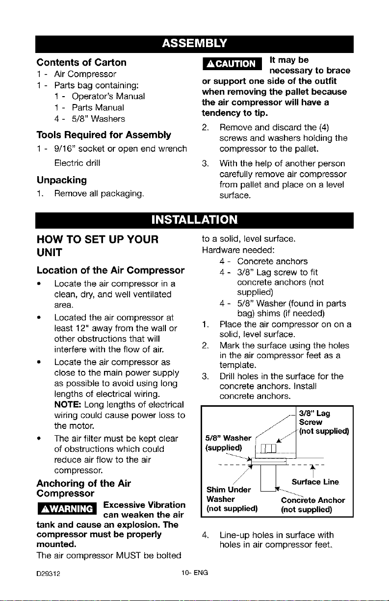
The air compressor MUST be bolted
D29312 10- ENG
can weaken the air
to a solid, level surface.
Hardware needed:
4- Concrete anchors
4 - 3/8" Lag screw to fit
concrete anchors (not
supplied)
4 - 5/8" Washer (found in parts
bag) shims (if needed)
1. Place the air compressor on on a
solid, level surface.
2. Mark the surface using the holes
in the air compressor feet as a
template.
3. Drill holes in the surface for the
concrete anchors. Install
concrete anchors.
3/8" Lag
Screw
5/8" Washer
(supplied)
Shim Under
Washer Concrete Anchor
(not supplied) (not supplied)
(not supplied)
Surface Line
4. Line-up holes in surface with
holes in air compressor feet.

5. Place the (4) washers (supplied)
between the floor and air
compressor feet. If needed, solid
shims may be placed between
the washers and floor to evenly
distribute weight on all four feet.
See next figure.
6. Place the (4) 3/8" lag screws
through the air compressor feet,
washers, shims, and into the
anchors.
7. Torque 3/8" lag screws to 7-10
ft.-Ibs.
Wiring Instructions
_ RISK OF
ELECTRICAL
SHOCK. Improper electrical
grounding can result in electrical
shock. The wiring should be done
by a qualified electrician
A qualified electrician needs to knows
the following before wiring:
1. The amperage rating of the
electrical box should be
adequate. Refer to the
Specification Chart, in the parts
manual, for this information.
2. The supply line should have the
same electrical characteristics
(voltage, cycle, phase) as the
motor. Refer to the motor
nameplate, on side of motor, for
this information.
NOTE: The wiring must be the same
as the motor nameplate voltage plus
or minus 10%. Refer to local codes
for recommended wire sizes, correct
wire size, and maximum wire run;
undersize wire causes high amp draw
and overheating to the motor.
Electrical wiring
must be located
away from hot surfaces such as
manifold assembly, compressor
outlet tubes, heads, or cylinders.
GROUNDING INSTRUCTIONS
This product should be connected to
a metallic, permanent wiring system,
of an equipment-grounding terminal
or lead on the product.
Voltage and Circuit Protection
Refer to the Parts Manual for the
voltage and minimum branch circuit
requirements.
Certain air compressors can be
operated on a 15 amp circuit if the
following conditions are met.
1. Voltage supply through branch
circuit is 15 amps.
2. Circuit is not used to supply any
other electrical needs (lights,
appliances, etc.).
3. Circuit is equipped with a 15
amp circuit breaker or 15 amp
time delay fuse. NOTE: If
compressor is connected to a
circuit protected by fuses, use
only time delay fuses. Time delay
fuses should be marked "D" in
Canada and "T" in the US.
If any of the above conditions cannot
be met, or if operation of the
compressor repeatedly causes
interruption of the power, it may be
necessary to operate it from a 20
amp circuit.
Air Distribution System
Plastic or PVC pipe
is not designed for
use with compressed air.
Regardless of its indicated
pressure rating, plastic pipe can
burst from air pressure. Use only
metal pipe for air distribution lines.
The next figure represents a typical
air distribution system. The following
are tips to remember when setting up
the air compressor's air distribution
system.
11_ENG D29312
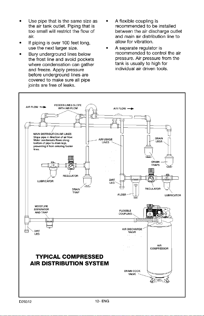
Use pipe that is the same size as
the air tank outlet. Piping that is
too small will restrict the flow of
air.
If piping is over 100 feet long,
use the next larger size.
Bury underground lines below
the frost line and avoid pockets
where condensation can gather
and freeze. Apply pressure
before underground lines are
covered to make sure all pipe
joints are free of leaks.
A flexible coupling is
recommended to be installed
between the air discharge outlet
and main air distribution line to
allow for vibration.
A separate regulator is
recommended to control the air
pressure. Air pressure from the
tank is usually to high for
individual air driven tools.
AIR FLOW _ WiTH AiR FLOW
MAiN OISTRIBUTiON A_R LINES
S_Ope pipe in direction of air ftow.
Water condensate flows a_ng
prevent_n 9 _ fr_ entering feeder
_ines.
_bottom of pipe to drain legs,
LUBRICATOR
SEPA_TOR
AND TRAP
_MOtSTURE
LEG
FEEDER LINES SLOPE
DP_IN _
TRAp
TYPICAL COMPRESSED
AIR DISTRIBUTION SYSTEM
AiR USAGE
LINES
VALVE
DRAIN COCK
VALVE
A_R
COMPRESSOR
D29312 12- ENG
Know Your Air Compressor
READ THIS OWNER'S MANUAL AND SAFETY RULES BEFORE OPERATING
YOUR UNIT. Compare the illustrations with your unit to familiarize yourself with
the location of various controls and adjustments. Save this manual for future
reference.
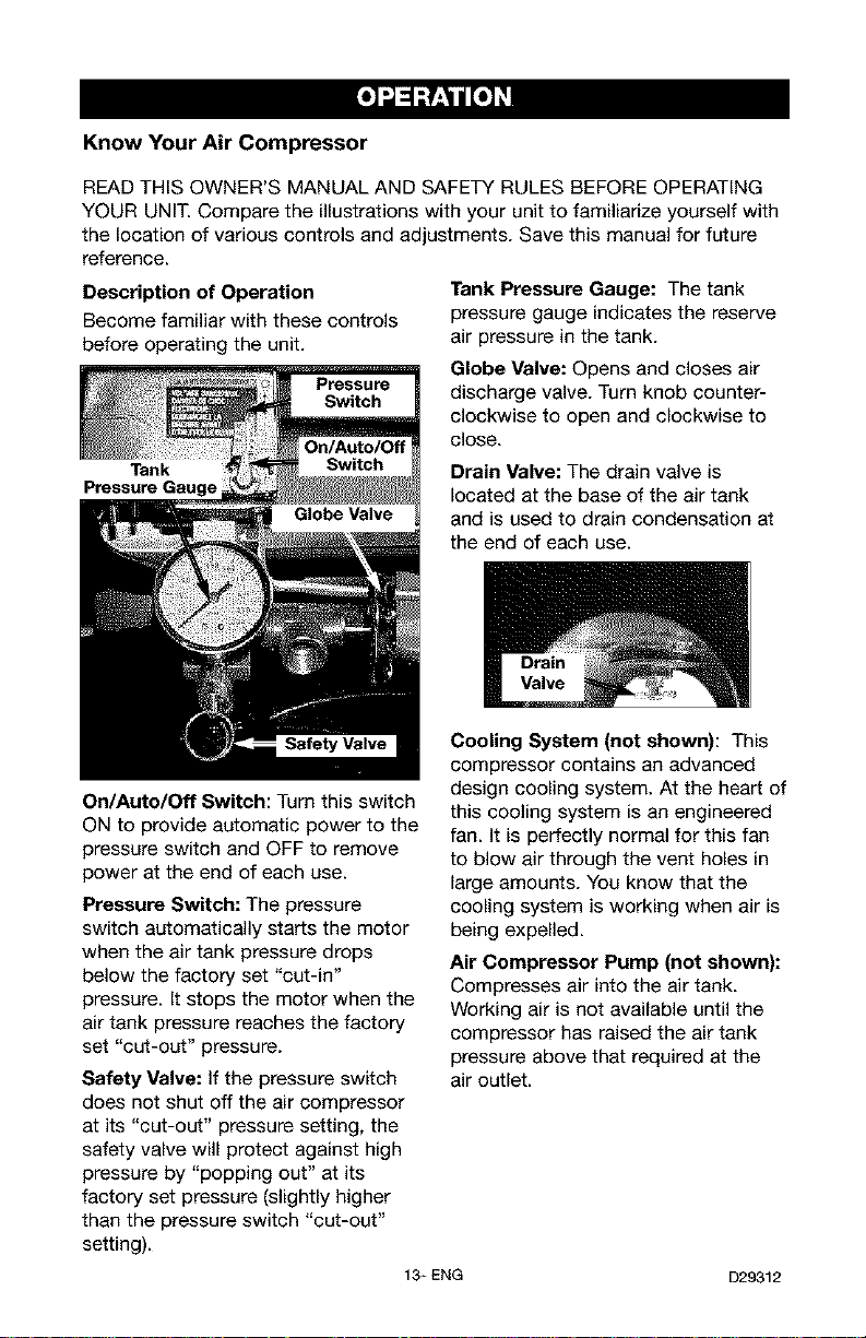
Description of Operation
Become familiar with these controls
before operating the unit.
Tank
On/Auto/Off Switch: Turn this switch
ON to provide automatic power to the
pressure switch and OFF to remove
power at the end of each use.
Pressure Switch: The pressure
switch automatically starts the motor
when the air tank pressure drops
below the factory set "cut-in"
pressure. It stops the motor when the
air tank pressure reaches the factory
set "cut-out" pressure.
Safety Valve: If the pressure switch
does not shut off the air compressor
at its "cut-out" pressure setting, the
safety valve will protect against high
pressure by "popping out" at its
factory set pressure (slightly higher
than the pressure switch "cut-out"
setting).
Tank Pressure Gauge: The tank
pressure gauge indicates the reserve
air pressure in the tank.
Globe Valve: Opens and closes air
discharge valve. Turn knob counter-
clockwise to open and clockwise to
close.
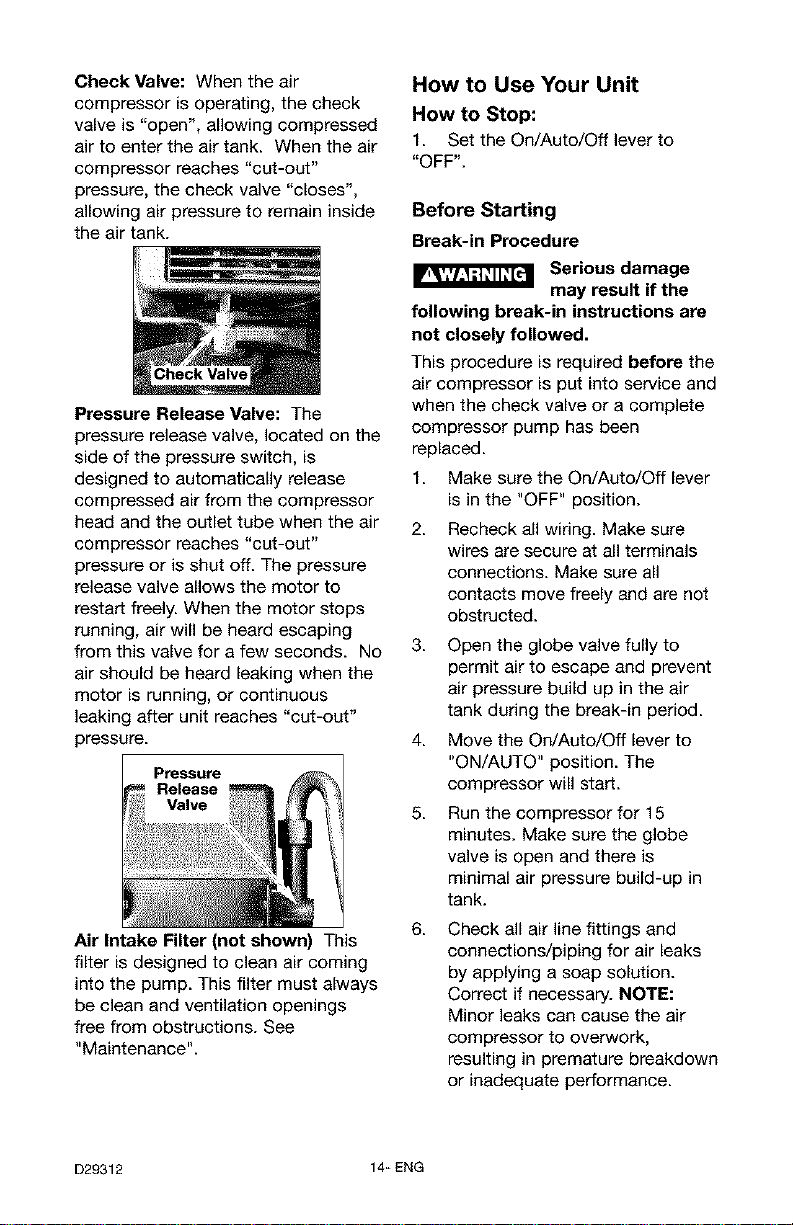
Drain Valve: The drain valve is
located at the base of the air tank
and is used to drain condensation at
the end of each use.
Cooling System (not shown): This
compressor contains an advanced
design cooling system. At the heart of
this cooling system is an engineered
fan. It is perfectly normal for this fan
to blow air through the vent holes in
large amounts. You know that the
cooling system is working when air is
being expelled.
Air Compressor Pump (not shown):
Compresses air into the air tank.
Working air is not available until the
compressor has raised the air tank
pressure above that required at the
air outlet.
13_ENG
D29312
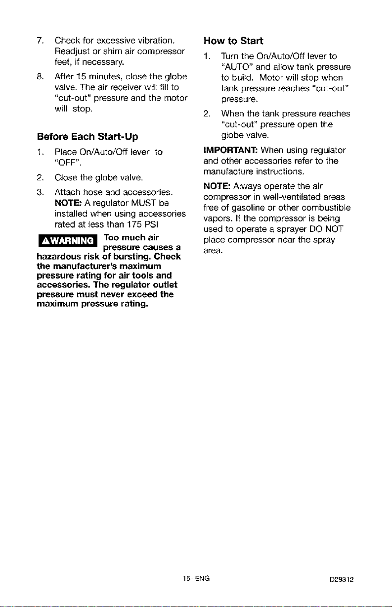
Check Valve: When the air
compressor is operating, the check
valve is "open", allowing compressed
air to enter the air tank. When the air
compressor reaches "cut-out"
pressure, the check valve "closes",
allowing air pressure to remain inside
the air tank.
How to Use Your Unit
How to Stop:
1. Set the On/Auto/Off lever to
"OFF".
Before Starting
Break-in Procedure
Pressure Release Valve: The
pressure release valve, located on the
side of the pressure switch, is
designed to automatically release
compressed air from the compressor
head and the outlet tube when the air
compressor reaches "cut-out"
pressure or is shut off. The pressure
release valve allows the motor to
restart freely. When the motor stops
running, air will be heard escaping
from this valve for a few seconds. No
air should be heard leaking when the
motor is running, or continuous
leaking after unit reaches "cut-out"
pressure.
Pressure
Release
Valve
Air Intake Filter (not shown) This
filter is designed to clean air coming
into the pump. This filter must always
be clean and ventilation openings
free from obstructions. See
"Maintenance".
_ Serious damage
may result if the
following break-in instructions are
not closely followed.
This procedure is required before the
air compressor is put into service and
when the check valve or a complete
compressor pump has been
replaced.
1. Make sure the On/Auto/Off lever
is in the "OFF" position.
2. Recheck all wiring. Make sure
wires are secure at all terminals
connections. Make sure all
contacts move freely and are not
obstructed.
3. Open the globe valve fully to
permit air to escape and prevent
air pressure build up in the air
tank during the break-in period.
4. Move the On/Auto/Off lever to
"ON/AUTO" position. The
compressor will starL
5. Run the compressor for 15
minutes. Make sure the globe
valve is open and there is
minimal air pressure build-up in
tank.
6. Check all air line fittings and
connections/piping for air leaks
by applying a soap solution.
Correct if necessary. NOTE:
Minor leaks can cause the air
compressor to overwork,
resulting in premature breakdown
or inadequate performance.
D29312 14_ ENG
7. Check for excessive vibration.
Readjust or shim air compressor
feet, if necessary.
8. After 15 minutes, close the globe
valve. The air receiver will fill to
"cut-out" pressure and the motor
will stop.
Before Each Start-Up
1. Place On/Auto/Off lever to
"OFF".
2. Close the globe valve.
3. Attach hose and accessories.
NOTE: A regulator MUST be
installed when using accessories
rated at less than 175 PSI
Too much air
hazardous risk of bursting. Check
the manufacturer's maximum
pressure rating for air tools and
accessories. The regulator outlet
pressure must never exceed the
maximum pressure rating.
pressure causes a
How to Start
1. Turn the On/Auto/Off lever to
"AUTO" and allow tank pressure
to build. Motor will stop when
tank pressure reaches "cut-out"
pressure.
2. When the tank pressure reaches
"cut-out" pressure open the
globe valve.
IMPORTANT: When using regulator
and other accessories refer to the
manufacture instructions.
NOTE: Always operate the air
compressor in well-ventilated areas
free of gasoline or other combustible
vapors. If the compressor is being
used to operate a sprayer DO NOT
place compressor near the spray
area.
15_ ENG D29312
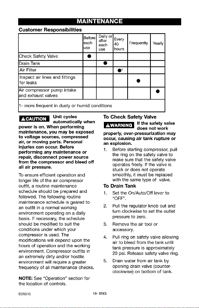
Customer Responsibilities
Before Daily ol
after Every
_ach each 40 Frequently
_se use hours
Check Safety Valve
Drain Tank
Air Filter
Inspect air lines and fittings
for leaks
Air compressor pump intake
and exhaust valves
1- more frequent in dusty or humid conditions
Yearly
1
Unit cycles
automatically when
power is on. When performing
maintenance, you may be exposed
to voltage sources, compressed
air, or moving parts. Personal
injuries can occur. Before
performing any maintenance or
repair, disconnect power source
from the compressor and bleed off
all air pressure.
To ensure efficient operation and
longer life of the air compressor
outfit, a routine maintenance
schedule should be prepared and
followed. The following routine
maintenance schedule is geared to
an outfit in a normal working
environment operating on a daily
basis. If necessary, the schedule
should be modified to suit the
conditions under which your
compressor is used. The
modifications will depend upon the
hours of operation and the working
environment. Compressor outfits in
an extremely dirty and/or hostile
environment will require a greater
frequency of all maintenance checks.
NOTE: See "Operation" section for
the location of controls.
To Check Safety Valve
If the safety valve
does not work
properly, over-pressurization may
occur, causing air tank rupture or
an explosion,
1. Before star_ing compressor, pull
the ring on the safety valve to
make sure that the safety valve
operates freely. If the valve is
stuck or does not operate
smoothly, it must be replaced
with the same type of valve.
To Drain Tank
1. Set the On/Auto/Off lever to
"OFF".
2. Pull the regulator knob out and
turn clockwise to set the outlet
pressure to zero.
3. Remove the air tool or
accessory.
4.
Pull ring on safety valve allowing
air to bleed from the tank until
tank pressure is approximately
20 psi. Release safety valve ring.
5. Drain water from air tank by
opening drain valve (counter-
clockwise) on bottom of tank.
D29312 16_ ENG
 Loading...